EP1816039A1 - Keyless entry system - Google Patents
Keyless entry system Download PDFInfo
- Publication number
- EP1816039A1 EP1816039A1 EP20070002114 EP07002114A EP1816039A1 EP 1816039 A1 EP1816039 A1 EP 1816039A1 EP 20070002114 EP20070002114 EP 20070002114 EP 07002114 A EP07002114 A EP 07002114A EP 1816039 A1 EP1816039 A1 EP 1816039A1
- Authority
- EP
- European Patent Office
- Prior art keywords
- vehicle
- movement
- portable device
- data group
- data
- Prior art date
- Legal status (The legal status is an assumption and is not a legal conclusion. Google has not performed a legal analysis and makes no representation as to the accuracy of the status listed.)
- Granted
Links
Images



Classifications
-
- B—PERFORMING OPERATIONS; TRANSPORTING
- B60—VEHICLES IN GENERAL
- B60R—VEHICLES, VEHICLE FITTINGS, OR VEHICLE PARTS, NOT OTHERWISE PROVIDED FOR
- B60R25/00—Fittings or systems for preventing or indicating unauthorised use or theft of vehicles
- B60R25/20—Means to switch the anti-theft system on or off
- B60R25/24—Means to switch the anti-theft system on or off using electronic identifiers containing a code not memorised by the user
Definitions
- the present invention relates to keyless entry systems that lock/unlock doors of a vehicle by performing wireless communication between an on-vehicle device and a portable device. More particularly, the present invention relates to a keyless entry system capable of accurately determining whether the portable device resides outside or inside of a predetermined boundary set with respect to the vehicle.
- an on-vehicle device includes a plurality of transmitting antennas attached at various places of the vehicle. The on-vehicle device determines that the portable device resides inside the vehicle if the portable device receives a radio wave from the transmitting antennas attached inside the vehicle. On the other hand, the on-vehicle device determines that the portable device resides outside the vehicle if the portable device receives a radio wave from the transmitting antennas attached outside the vehicle.
- An inside data group and an outside data group are obtained beforehand.
- the inside data group has intensity information of a plurality of signals transmitted from a plurality of transmitting antennas of the vehicle when a portable device is placed along an inner surface of the vehicle.
- the outside data group has intensity information of a plurality of signals transmitted from the plurality of transmitting antennas of the vehicle when a portable device is placed along an outer surface of the vehicle. Whether the portable device resides inside or outside the vehicle is determined by determining which of the inside data group and the outside data group the intensity data of the signal transmitted from each of the transmitting antennas and detected by the portable device closely resembles.
- the transmitting antennas are attached to closable side mirrors of the vehicle.
- the inside data group and the outside data group are obtained with the side mirrors being opened.
- the above-cited invention permits the determination of whether the portable device resides inside or outside the vehicle to be performed accurately if the side mirrors are opened.
- the strength of the signal detected by the portable device changes due to the change in the position of the transmitting antennas attached to the vehicle, which undesirably decreases the accuracy of the determination.
- This problem is not specific to a case where the transmitting antennas are attached to the side mirrors, and occurs when the transmitting antennas are attached to movable objects of the vehicle.
- the transmitting antennas are not attached to movable objects, movement of the movable objects may affect the radio wave transmitted from the transmitting antennas. In such a case, the strength of the signal detected by the portable device changes before and after the movement of the movable objects, which decreases the accuracy of the determination.
- the determination of the position of the portable device is not limited to the determination of whether the portable device resides inside or outside the vehicle, and whether the portable device resides inside or outside of a boundary apart from the door by predetermined distance can also be determined.
- a light may be turned on upon determining that the portable device is within a radius of a predetermined distance from, for example, the door.
- a keyless entry system that can determine the position inside or outside a predetermined boundary, which is not limited to a boundary defining inside and outside of a vehicle, is desired.
- the present invention is made in view of the above-described problems. It is an object of the present invention to provide a keyless entry system that can accurately determine the position of a portable device even if a transmitting antenna is attached to a movable object of a vehicle or in a manner that the transmitted radio wave is affected by the movable object.
- a keyless entry system includes: an on-vehicle device having an on-vehicle transmitting unit having a plurality of transmitting antennas, attached to a vehicle, for transmitting a request signal, at least one of the plurality of transmitting antennas being attached to a movable object installed in the vehicle or at a place where movement of the movable object affects a transmitted radio wave, an on-vehicle receiving unit for receiving an answer signal, and an on-vehicle control unit for performing a predetermined control operation after authenticating the answer signal transmitted from a portable device; and the portable device having a portable device receiving unit for receiving the request signal, a portable device transmitting unit for transmitting the answer signal, and a portable device control unit for detecting the strength of each signal transmitted from the plurality of transmitting antennas in the on-vehicle device.
- the on-vehicle control unit or the portable device control unit has a memory for storing data, the memory storing a first data group or a first parameter and a second data group or a second parameter, the first data group having signal strength information of each received signal transmitted from the plurality of transmitting antennas before and after the movement of the movable object when the portable device is placed along one side of a predetermined boundary set with respect to the vehicle, the first parameter being necessary for comparing the first data group and signal strength information, the second data group having signal strength information of each received signal transmitted from the plurality of transmitting antennas before and after the movement of the movable object when the portable device is placed along the other side of the predetermined boundary set with respect to the vehicle, and the second parameter being necessary for comparing the second data group and signal strength information.
- the on-vehicle control unit or the portable device control unit having the memory determines, using the first and second data groups or the first and second parameters, which of the first and second data groups the strength information obtained by receiving the signals transmitted from the plurality of the transmitting antennas by the portable device closely resembles.
- a keyless entry system includes: an on-vehicle device having an on-vehicle transmitting unit having a plurality of transmitting antennas, attached to a vehicle, for transmitting a request signal, at least one of the plurality of transmitting antennas being attached to a movable object installed in the vehicle or at a place where movement of the movable object affects a transmitted radio wave, an on-vehicle receiving unit for receiving an answer signal, and an on-vehicle control unit for performing a predetermined control operation after authenticating the answer signal transmitted from the portable device; and a portable device having a portable device receiving unit for receiving the request signal, a portable device transmitting unit for transmitting the answer signal, and a portable device control unit for detecting the strength of each signal transmitted from the plurality of transmitting antennas in the on-vehicle device.
- a detecting unit for detecting the movement of the movable object is provided on the movable object and connected to the on-vehicle control unit so that the detecting unit sends movement state information of the movable object to the on-vehicle control unit.
- the on-vehicle control unit has a memory storing data, the memory storing a pre-movement first data group or a pre-movement first parameter, a post-movement first data group or a post-movement first parameter, a pre-movement second data group or a pre-movement second parameter, and a post-movement second data group or a post-movement second parameter, the pre-movement first data group having signal strength information obtained by receiving signals transmitted from the plurality of transmitting antennas by the portable device before the movement of the movable object when the portable device is placed along one side of a predetermined boundary set with respect to the vehicle, the pre-movement first parameter being necessary for comparing the pre-movement first data group and the signal strength information, the post-mov
- the on-vehicle control unit determines, using the pre-movement first and second data groups or the pre-movement first and second parameters, which of the pre-movement first and second data groups the signal strength information obtained by receiving the signals transmitted from the plurality of the transmitting antennas by the portable device closely resembles, whereas, when the movement state information sent from the detecting unit indicates a state after the movement of the movable object, the on-vehicle control unit determines, using the post-movement first and second data groups or the post-movement first and second parameters, which of the post-movement first and second data groups the signal strength information obtained by receiving the signals transmitted from the plurality of the transmitting antennas by the portable device closely resembles.
- the predetermined boundary set with respect to the vehicle may be a boundary defining the inside and outside of the vehicle.
- the predetermined boundary set with respect to the vehicle may be a boundary outward from the vehicle and apart from a transmitting antenna attached near a door of the vehicle by a predetermined distance.
- the on-vehicle control unit or the portable device control unit may calculate a Mahalanobis distance between the strength information of the signals and each of the data groups using each of the data groups or each of the parameters, and determine the signal strength information closely resembles the data group having smaller Mahalanobis distance.
- the keyless entry system includes the memory storing the first data group or the first parameter and the second data group or the second parameter.
- the first data group has signal strength information of a request signal transmitted from the plurality of transmitting antennas before and after the movement of the movable object when the portable device is placed along one side of a predetermined boundary set with respect to the vehicle.
- the second data group has signal strength information of a request signal transmitted from the plurality of transmitting antennas before and after the movement of the movable object when the portable device is placed along the other side of the predetermined boundary set with respect to the vehicle.
- the on-vehicle control unit or the portable device control unit determines which of the first and second data groups the strength information of the request signal closely resembles.
- the keyless entry system can accurately determine the position of the portable device before and after the movement of the movable device, when the transmitting antennas are attached to the movable object installed in the vehicle or at a place where the movement of the movable object affect the radio wave.
- the detecting unit for detecting the movement is provided on the movable object.
- the keyless entry system includes a memory storing the pre-movement first data group and the post-movement first data group or the parameters necessary for resemblance determination corresponding to these data groups, and the pre-movement second data group and the post-movement second data group or the parameters necessary for resemblance determination corresponding to these data groups.
- the pre-movement and post-movement first data groups have signal strength information of the request signal transmitted from the plurality of transmitting antennas before and after the movement of the movable object, respectively, when the portable device is placed along one side of a predetermined boundary set with respect to the vehicle.
- the pre-movement and post-movement second data groups have signal strength information of the request signal transmitted from the plurality of transmitting antennas before and after the movement of the movable object, respectively, when the portable device is placed along the other side of the predetermined boundary set with respect to the vehicle.
- the on-vehicle control unit uses the different pre-movement and post-movement data groups or parameters according to the movement state of the movable object detected by the detecting unit.
- the predetermined boundary set with respect to the vehicle may be a boundary defining the inside and outside of the vehicle.
- the predetermined boundary set with respect to the vehicle may be a boundary outward from the vehicle and apart from a transmitting antenna attached near a door of the vehicle by a predetermined distance.
- the on-vehicle control unit or the portable device control unit may calculate a Mahalanobis distance between the strength information of the signals and each of the data groups using each of the data groups or each of the parameters, and determine the signal strength information closely resembles the data group having smaller Mahalanobis distance.
- the keyless entry system can determine the position more accurately.
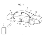
- Fig. 1 shows a schematic diagram of a keyless entry system according to the embodiment of the present invention.
- the keyless entry system according to the embodiment locks/unlocks a door 1A of a vehicle 1.
- An on-vehicle device 2 is installed in the vehicle 1.
- a user carries a portable device 3 and gives instructions, such as an authentication instruction and locking/unlocking instructions, by performing wireless communication between the on-vehicle device 2 and the portable device 3.
- the on-vehicle device 2 has a plurality of transmitting antennas 15 attached at various places of the vehicle 1. Request signals are transmitted from each of the transmitting antennas 15 to the portable device 3.
- the request signals may be low frequency signals.
- At least one of the transmitting antennas 15 is attached to a side mirror 1B, which is one of movable objects installed in the vehicle.
- the side mirror 1B is attached near a front end part of a front door 1A, and is automatically or manually opened/closed.
- Fig. 1 shows a state where the side mirror 1B is opened.
- the vehicle 1 is parked at a parking lot or the like, it is possible to make a part of the side mirror 1B projecting from the side of the vehicle 1 smaller by closing the side mirror 1B so that the mirror surface is turned inside. Accordingly, a position of the transmitting antenna 15 attached to the side mirror 1B changes as the side mirror 1B is opened/closed.
- the user carrying the portable device 3 has to press a request switch 16 provided near a doorknob 1C of a door 1A to unlock the door 1A.
- communication such as authentication
- the on-vehicle device 2 unlocks the door 1A.
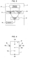
- Figs. 2 and 3 show configurations of the on-vehicle device 2 and the portable device 3, respectively.
- the on-vehicle device 2 has an on-vehicle receiving unit 10 for receiving answer signals from the portable device 3, an on-vehicle transmitting unit 11 for transmitting request signals to the portable device 3, and an on-vehicle control unit 12 for performing various control operations in response to reception of the answer signals and pressing of the request switch 16.
- the on-vehicle control unit 12 is connected to a memory 13 and the above-mentioned request switch 16.
- the memory 13 stores information necessary for the control operations, such as a V-ID (Vehicle-ID), which is an identification code unique to each vehicle, and IDs of a plurality of portable devices capable of remotely operating the vehicle.
- V-ID Vehicle-ID
- the on-vehicle receiving unit 10 is connected to a receiving antenna 14 for receiving answer signals.
- the on-vehicle transmitting unit 11 is connected to a plurality of transmitting antennas 15A to 15F for transmitting request signals.
- the plurality of transmitting antennas 15A to 15F is attached at various places inside and outside the vehicle 1.
- the portable device 3 has a portable device receiving unit 20 for receiving request signals from the on-vehicle device 2, a portable device transmitting unit 21 for transmitting answer signals to the on-vehicle device 2, a portable device control unit 22 for performing various control operations in response to reception of the request signals, and a memory 24 storing an ID set for the portable device 3, the V-ID, etc.
- a triaxial antenna 23 enabling reception/transmission of the request signals and the answer signals is connected to the portable device receiving unit 20 and the portable device transmitting unit 21.
- a wave-up signal included in the request signal received by the portable device receiving unit 20 from the on-vehicle device 2 switches a state of the portable device control unit 22 from a sleep mode into a normal operational mode. In the sleep mode, the power consumption is substantially equal to zero. Additionally, the portable device control unit 22 performs various operations on the basis of commands included in the request signals.
- Fig. 4 shows an arrangement of the receiving antenna 14 and the transmitting antennas 15A to 15F attached to the vehicle 1.
- the receiving antenna 14 is attached at a place inside the vehicle 1.
- the transmitting antennas 15A to 15F are attached at a plurality of places inside and outside the vehicle 1.
- three transmitting antennas 15A to 15C are attached inside the vehicle 1
- three transmitting antennas 15D to 15F are attached outside the vehicle 1.
- the transmitting antennas 15D and 15E are attached at the side mirrors 1B of the vehicle 1.
- the memory included in the on-vehicle device 2 stores IDs necessary for authenticating the portable device 3 and data used for determining the position of the portable device 3.
- the data used for determining the position of the portable device 3 may be parameters calculated from a first data group and a second data group.
- the first and second data groups have a plurality of data associating the strength of radio waves transmitted from each of the transmitting antennas 15 and received inside and outside the vehicle 1 and identification codes of the transmitting antennas 15.
- Each data of the first data group includes, regarding three signals having three strongest strength in the vehicle near a border between inside and outside the vehicle 1 among those transmitted from each of the transmitting antennas 15, the identification codes for identifying the transmitting antennas 15 and the strength of the radio waves corresponding to these antennas.
- Such data is obtained beforehand substantially around an inner surface of the vehicle 1.
- data of the second data group is obtained beforehand substantially around an outer surface near the border between the inside and outside the vehicle 1.
- the data of the second data group is obtained with the side mirror 1B, which is the movable object, being opened and also with the side mirror 1B being closed. All of the data collectively constitutes a second data group.
- both the data obtained with the side mirror 1B being opened and the data obtained with the side mirror 1B being closed collectively constitute a first data group.
- parameters used for calculating the Mahalanobis distance are calculated for each data group. These parameters are stored in the memory 13 as the data used for determining the position of the portable device 3.
- the portable device 3 When determining the position of the portable device 3, the portable device 3 first transmits data.
- the data includes, regarding the transmitting antennas 15 having transmitted signals having three strongest received signal strength among those transmitted from the transmitting antennas 15, identification codes for identifying the transmitting antennas 15 and the strength of the radio waves corresponding to these antennas.
- the on-vehicle control unit 12 calculates the Mahalanobis distance between the data transmitted from the portable device 3 and the first data group and the Mahalanobis distance between the transmitted data and the second data group using the parameters stored in the memory 13.
- the on-vehicle control unit 12 determines the smaller Mahalanobis distance, i.e., which data groups the data transmitted from the portable device 3 closely resembles, and determines that the portable device 3 resides on that side.
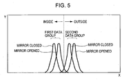
- Fig. 5 is a diagram conceptually showing distribution of each data group.
- the X-axis direction shows a position of the portable device 3 with respect to a contour of a vehicle in a plane perpendicular to the contour of the vehicle
- the Y-axis direction shows a frequency of appearance of measured data (the number of times that the data is measured). More specifically, the portable device 3 is placed at a plurality of points along the contour of the vehicle, and position of the portable device 3 is calculated on the basis of the strength data obtained from each of the points. The data is collected and plotted while assigning the position to the X-axis and the number of times that the data is measured to the Y-axis.
- positions in the X-axis direction of peaks in the frequency shown in the Y-axis direction differ between the first data group obtained along the inner surface of the vehicle 1 and the second data group obtained along the outer surface of the vehicle 1. Additionally, in each of the first and second data groups, although most of data overlaps, the positions in the X-axis direction of the peaks in the frequency differ between when the side mirror 1B is opened and when the side mirror 1B is closed. In the embodiment, both the data obtained with the side mirror 1B being closed and the data, which has a frequency peak at the different position, obtained with the side mirror 1B being closed are combined to constitute the first data group, which includes the data obtained when the portable device 3 is placed along the inner surface of the vehicle 1.
- both the data obtained with the side mirror 1B being opened and the data obtained with the side mirror 1B being closed are combined, a Mahalanobis reference space is set, and a value of each parameter used for determining the Mahalanobis distance is determined.
- the determination of which of the data groups the strength information closely resembles is performed with respect to a border at the position of a broken line shown in Fig. 5, that is, the position corresponding to the middle of the first and second data groups.
- the position inside or outside the vehicle is determined by determining which data groups the strength information closely resembles.
- the data is obtained with the side mirror 1B being closed and the side mirror 1B is opened at the time of actual use.
- the border when the side mirror 1B is closed locates at the middle of the first and second data groups obtained with the mirror being closed, the border locates on the left side, in the X-axis direction, of the broken line shown in Fig. 5.
- the side mirror 1B is opened, as is clear from the fact that the data groups are generally shifted to the right in the X-axis direction, the data obtained by the portable device 3 is shifted to the right compared with the data obtained with the side mirror 1B being closed.
- the border is also shifted to the right. Accordingly, even if the portable device 3 resides inside the vehicle, the possibility of determining that the portable device 3 resides on the right side of the border, i.e., outside the vehicle, increases, which in turn decreases the determination accuracy.
- the highly accurate determination can be performed regardless of the state (opened/closed) of the side mirror 1B.
- Fig. 6 shows a flowchart regarding an operation performed when unlocking a door.
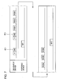
- Fig. 7 shows a chart of signals transmitted from the on-vehicle device 2 and the portable device 3 during the operation shown in the flowchart of Fig. 6.
- pressing the request switch 16 provided on the vehicle 1 causes the on-vehicle device 2 and the portable device 3 to perform wireless communication, and then the door is unlocked.
- the flowchart starts when a user presses the request switch 16 on the vehicle 1 (S1).
- the on-vehicle control unit 12 causes the on-vehicle transmitting unit 11 to transmit a request signal LF1 (S2).
- the request signal LF1 includes a signal A and a command signal CMD.
- the signal A contains a wake-up signal
- the command signal CMD contains information of the V-ID (Vehicle-ID), which is an identification code unique to the vehicle.
- the portable device control unit 22 After the portable device 3 receives the request signal LF1 by the portable device receiving unit 20, the portable device control unit 22 is put into the normal operational state from the sleep state by the wake-up signal. The portable device control unit 22 then determines whether or not the V-ID contained in the request signal LF1 agrees with the V-ID stored therein. At this time, if the V-IDs disagree, the operation shown in the flowchart is finished. If the V-IDs agree, the portable device control unit 22 causes the portable device transmitting unit 21 to transmit an answer signal RF1 (S5).
- the on-vehicle control unit 12 causes the on-vehicle transmitting unit 11 to transmit a location signal LF2.
- the location signal LF2 includes a signal constituted by the signal A and the command signal CMD, and a plurality of Rssi measurement signals sequentially transmitted from each of the transmitting antennas 15A to 15F.
- the signal A like the request signal LF1, contains the wave-up signal as well as an ID of the portable device.
- the signal A is transmitted from all of the transmitting antennas 15A to 15F.
- the Rssi measurement signals transmitted from each of the transmitting antennas 15A to 15F are pulse-like signals that have predetermined strength and continue for a predetermined time, and are used for measuring the received signal strength by the portable device 3. Since the on-vehicle transmitting unit 11 transmits each of the Rssi measurement signals from each of the transmitting antennas 15A to 15F in a predetermined order and at predetermined intervals, the portable device 3 can identify the transmitting antenna 15 that transmitted the Rssi measurement signal by the receiving timings.
- the portable device receiving unit 20 of the portable device 3 receives the location signal LF2 including the Rssi measurement signals transmitted from each of the transmitting antennas 15A to 15F (S8).
- the portable device control unit 22 measures the strength of each of the Rssi measurement signals in a manner as described above. Regarding three strongest data, the portable device transmitting unit 21 transmits the identification codes identifying the transmitting antennas 15 and the strength data corresponding to these antennas to the on-vehicle device 2 as an answer signal RF2 (S9). At this time, the answer signal RF2 including an HU-ID, which is uniquely set for each portable device, is transmitted.
- the signal strength measuring method is not limited to a method of measuring the strength of the Rssi measurement signals having been transmitted from the vehicle 1 by the portable device 3, and may be a method of directly measuring the strength of the request signals transmitted from the vehicle 1.
- the on-vehicle receiving unit 10 of the on-vehicle device 2 receives the answer signal RF2 from the portable device 3 (S10).
- the on-vehicle control unit 12 determines whether or not the HU-ID included in the answer signal agrees with the ID registered in the vehicle (S11). At this time, if the HU-ID disagrees with the one registered in the vehicle, the operation shown in the flowchart is finished. On the other hand, if the HU-ID agrees with the one registered in the vehicle, the on-vehicle control unit 12 determines the position of the portable device 3 next (S12).
- each portable device 3 When transmitting and receiving the request signal LF1, each portable device 3 transmits the answer signal RF1 after different time periods since the transmission of the request signal LF1. By measuring this time period, the responded portable device 3 is rapidly and easily identified among the plurality of portable devices 3.
- transmitting and receiving the request signal LF2 using the ID uniquely, having a larger information amount, set for the portable device, accurate authentication and confirmation of the position are firstly performed for the portable device 3 detected using the request signal LF1. If the authentication fails, the same operation is performed for each of the portable devices 3. Only authentication of the portable device 3 may be performed without identifying the portable device 3 using the request signal. Alternatively, authentication of each of the portable devices 3 may be performed after transmitting the Rssi measurement signals.
- the Mahalanobis distances between the data detected by the portable device 3 and the first data group and between the detected data and the second data group are calculated using the identification codes and the strength data included in the answer signal RF2 transmitted from the portable device 3 and the parameters stored in the memory 13. If the detected data closely resembles the first data group, the portable device 3 is determined to reside inside the vehicle 1, whereas if the detected data closely resembles the second data group, the portable device 3 is determined to reside outside the vehicle 1.
- the on-vehicle control unit 12 performs different control operations depending on whether the portable device 3 resides inside or outside the vehicle 1 (S13). If the portable device 3 is determined not to reside outside the vehicle 1, that is, if the portable device 3 is determined to reside inside the vehicle 1, the operation of the flowchart is finished.
- the portable device 3 When a user unlocks the door by pressing the request switch 16, the portable device 3 should be outside the vehicle 1. If the keyless entry system is configured to unlock the door when the portable device 3 resides inside the vehicle 1 with the user, even a person not carrying the portable device 3 can unlock the door by pressing the request switch 16. To prevent this, the keyless entry system is configured not to unlock the door when the portable device 3 resides inside the vehicle 1.
- the on-vehicle device 2 outputs an unlock instruction signal to a door locking device (not shown) so as to unlock the door (S14). Since the position of the portable device 3 is determined by calculating the Mahalanobis distance from the first and second data groups, the position can be determined accurately, which thus can reduce the frequency of the false unlocking operation.
- the first and second data groups are constituted by combining the data obtained before and after the movement of the side mirror 1B, which is a movable object of the vehicle 1. Thus, the position of the portable device 3 can be determined accurately regardless of the state (opened/closed) of the side mirror 1B.
- the position of the portable device 3 is determined in the same manner, and a control operation can be performed according to the determination result.
- other operations not limited to the operation of locking/unlocking the door, such as an operation of starting an engine according to the position of the portable device 3, the position of the portable device 3 is determined in the same manner, and a control operation can be performed according to the determination result.
- the position determination is not limited to this particular example. In another example of the position determination, whether the portable device 3 resides inside or outside the boundary outward from the vehicle 1 and apart from the vehicle 1 by a predetermined distance is determined. Here, the determination is performed with respect to the boundary apart from the transmitting antenna 15 attached to the side mirror 1B of the vehicle 1 by 1.5 meter.
- each data of the first data group is obtained along a surface, on the side where the vehicle 1 is located, apart from the boundary by five centimeters.
- the boundary is apart from the transmitting antenna attached to the side mirror 1B of the vehicle 1 by 1.5 meter.
- the data obtained here is the same as the data described above. More specifically, the data includes, regarding the transmitting antennas 15 having transmitted signals having three strongest received signal strength among those transmitted from the transmitting antennas 15, identification codes for identifying the transmitting antennas 15 and the strength of the radio waves corresponding to these antennas.
- each data of the second data group is obtained along a surface, on the opposite side of the vehicle 1, apart from the boundary by five centimeters. The boundary is apart from the transmitting antenna attached to the side mirror 1B of the vehicle 1 by 1.5 meter.
- the data is obtained with the side mirror 1B, i.e., the movable object, being opened and closed, and collectively constitutes each data group.
- Parameters used for calculating the Mahalanobis distance are calculated from each of these data groups and stored in the memory 13.
- the on-vehicle control unit 12 calculates each of the Mahalanobis distances between the data from the portable device 3 and the first data group and between the data and the second data group using the parameters stored in the memory 13.
- the on-vehicle control unit 12 determines whether the portable device 3 resides outside or inside the boundary. More specifically, the on-vehicle control unit 12 determines whether the portable device 3 is apart from the vehicle 1 by 1.5 meter or more or within a radius of 1.5 meter.
- the on-vehicle control unit 12 performs control operations according to the determination result. For example, if the portable device 3 is determined to be within a radius of 1.5 meter, a light, provided near the door of the vehicle 1, for illuminating a riding position is turned on. This configuration allows the user to easily get into the vehicle 1 and allows the vehicle 1 to inform the user that the vehicle 1 has recognized the existence of the portable device 3.
- the boundary with respect to which the position of the portable device 3 is determined is not limited to the boundary defining the inside and outside the vehicle, and may be any boundaries inside or outside the vehicle set with respect to the vehicle 1.
- the boundary is set at a surface between the drive's seat and the passenger's seat in the vehicle 1.
- the data of the first data group is obtained along one side of the boundary and the data of the second data group is obtained along the other side of the boundary. Then, the parameters used for calculating the Mahalanobis distance are calculated.
- each of the Mahalanobis distances between the data from the portable device 3 and the first data group and between the data and the second data group is calculated. Then, whether the portable device 3 resides outside or inside the boundary, that is, whether the portable device 3 resides on the driver's seat side or on the passenger's seat side, is determined.
- FIG. 8 shows a schematic diagram of a keyless entry system according to the embodiment.
- the keyless entry system according to the embodiment has substantially the same configuration as that according to the first embodiment.
- the description of the points in common with the first embodiment is omitted, and only the difference will be described.
- the transmitting antenna 15 since the transmitting antenna 15 is not attached to the movable object, the position of the transmitting antenna 15 is fixed if the movable object moves. However, even if the transmitting antenna 15 is not attached to the movable object and the transmitting antenna 15 itself does not move, movement of the movable object may affect a radio wave transmitted from the transmitting antenna 15. For example, when the transmitting antenna 15 is attached near a side mirror 1B, i.e., the movable object, or near a seat that moves forward and backward inside the vehicle, the radio wave transmitted from the transmitting antenna is affected by the movement of the movable object. As shown in Fig. 8, in this embodiment, the transmitting antenna 15 is attached near the seat 1C in the vehicle, and movement of the seat 1C affects the transmitted radio wave.
- data of the first and second data groups is obtained on the both side of a randomly set boundary before and after the movement of the seat 1C, i.e., the movable object.
- the boundary may be any boundaries outside and inside the vehicle 1 in addition to the boundary defining the inside and outside of the vehicle. The rest is the same as the first embodiment.
- FIG. 9 shows a schematic diagram of a keyless entry system according to the embodiment.
- the keyless entry system according to the embodiment has substantially the same configuration as that according to the first embodiment.
- the description of the points in common with the first embodiment is omitted, and only the difference will be described.
- a detecting unit 17 for detecting a movement state of a side mirror 1B is attached to the side mirror 1B of a vehicle 1.
- the detecting unit 17 includes, for example, a limit switch or the like, and is capable of detecting a closed state or a opened state, which is a state before and after the movement of the side mirror 1B.
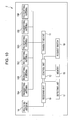
- Fig. 10 shows a block diagram of an on-vehicle device 2 according to the embodiment. As shown in this figure, the detecting unit 17 is connected to an on-vehicle control unit 12 of the on-vehicle device 2 so that the detecting unit 17 can send the opened/closed state information of the side mirror 1B to the on-vehicle control unit 12.
- the first and second data groups are obtained beforehand, which is the same as in the case of the first embodiment.
- data is obtained before and after the movement of the side mirror 1B, i.e., the movable object, and treated as different data groups.
- the parameters used for calculating the Mahalanobis distance are calculated from the data groups, and stored in a memory 13. More specifically, the memory 13 stores parameters for a pre-movement first data group and a pre-movement second data group corresponding to the state where the side mirror 1B is opened, and parameters for a post-movement first data group and a post-movement second data group corresponding to the state where the side mirror 1B is closed.
- the on-vehicle control unit 12 When determining the position of the portable device 3, the on-vehicle control unit 12 first receives the opened/closed state information of the side mirror 1B from the detecting unit 17. When the side mirror 1B is opened, the on-vehicle control unit 12 reads out the parameters corresponding to the pre-movement first data group and the pre-movement second data group from the memory 13, and calculates the Mahalanobis distance using the parameters. On the other hand, when the side mirror 1B is closed, the on-vehicle control unit 12 reads out the parameters corresponding to the post-movement first data group and the post-movement second data group from the memory 13, and calculates the Mahalanobis distance using the parameters.
- the position of the portable device 3 can be accurately determined even if the transmitting antenna 15 is attached to the movable object.
- the state of the movable object can be obtained only when the detecting unit 17 is provided and operable.
- this configuration may not suitable for a case where the side mirror 1B is manually opened or closed.
- both the pre-movement parameters and the post-movement parameters have to be stored in the memory 13, the amount of the stored data becomes larger. For a case where these become problematic, it is preferable to use the first embodiment.
- whether the portable deice 3 resides inside or outside the vehicle 1 is determined.
- the position determination is not limited to this particular example, whether the portable device 3 resides inside or outside the boundary outward from the vehicle 1 and apart from the vehicle 1 by a predetermined distance, e.g., 1.5 meter, may be determined as in the case of the first embodiment.
- data of the data groups may be obtained with respect to the boundary between the driver's seat and the passenger's seat.
- third embodiment may be applied to the second embodiment.
- the pre-movement and post-movement data groups may be used for different circumstances by detecting the movement of the movable object that affects the transmitted radio wave.
- the embodiments of the present invention has been described above, application of the present invention is not limited to these embodiments, and various modifications are possible within the technical idea of the present invention.
- the number of the transmitting antennas 15 and the arrangement thereof are not limited to this particular example, and at least one transmitting antennas 15 may be attached inside and outside the vehicle 1. Nevertheless, the plurality of transmitting antennas 15 allows more accurate position determination.
- the number of the data is not limited to three, and all the data may be used.
- kinds of movable object is not limited to the side mirror 1B, and include, for example, a seat movable forward and backward and a height-adjustable steering wheel.
- data is obtained before and after the movement, and the position of the portable device 3 can be determined by separately or collectively using the data.
- the on-vehicle control unit 12 of the on-vehicle device 2 calculates the Mahalanobis distances between the data from the portable device 3 and the first data group and between the data and the second data group.
- the portable device 3 may have the similar memory as the memory 13. The parameters necessary for calculating the Mahalanobis distances for the first data group and the second data group may be stored in the memory.
- the portable device control unit 22 may be configured to calculate the Mahalanobis distances, and determine the position of the portable device 3.
- the data stored in the memory is not limited to the parameters necessary for calculating the Mahalanobis distance corresponding to each data group as in the case of the embodiments, and first and second data groups themselves may be stored in the memory.
- the parameters and the Mahalanobis distance are calculated from each data group. More specifically, although the first and second data groups are obtained at the time of the development or manufacture of the vehicle, calculation of the parameters, necessary for calculating the Mahalanobis distance, from each data group may be performed at any time after obtaining the data.
- the amount of the data stored in the memory 13 can be decreased by calculating the parameters beforehand and storing the parameters in the memory 13.
- the method for determining the position is not limited to the one calculating the Mahalanobis distance as in the case of the embodiments, and may be the one using a linear discriminant function.
- use of the Mahalanobis distance allows the position to be determined more accurately.
Landscapes
- Engineering & Computer Science (AREA)
- Mechanical Engineering (AREA)
- Lock And Its Accessories (AREA)
- Selective Calling Equipment (AREA)
Abstract
Description
- The present invention relates to keyless entry systems that lock/unlock doors of a vehicle by performing wireless communication between an on-vehicle device and a portable device. More particularly, the present invention relates to a keyless entry system capable of accurately determining whether the portable device resides outside or inside of a predetermined boundary set with respect to the vehicle.
- Keyless entry systems that perform wireless communication between an on-vehicle device installed in a vehicle and a portable device carried by users so as to lock/unlock doors of the vehicle have been known. Recently, passive keyless entry systems are also known. In the passive keyless entry systems, upon detecting approach of a portable device to a vehicle, communication is automatic-ally performed between an on-vehicle device and the portable device. The passive keyless entry systems lock/unlock doors of the vehicle after authenticating an ID uniquely set for each portable device. A keyless entry system described in Unexamined
Japanese Patent Application Publication No. 2002-77972 US Patent Application Publication No. 2002/0025823 ) is one of such keyless entry systems. - Particularly, it is important for passive keyless entry systems to be able to determine whether a portable device resides outside or inside of a vehicle. Thus, an on-vehicle device includes a plurality of transmitting antennas attached at various places of the vehicle. The on-vehicle device determines that the portable device resides inside the vehicle if the portable device receives a radio wave from the transmitting antennas attached inside the vehicle. On the other hand, the on-vehicle device determines that the portable device resides outside the vehicle if the portable device receives a radio wave from the transmitting antennas attached outside the vehicle.
- However, in known keyless entry systems, accuracy of determination of positions of portable devices is not sufficient. For example, when a radio wave transmitted from a transmitting antenna attached inside a vehicle leaks outside the vehicle, the portable device may be mistakenly determined to reside inside the vehicle even if the portable device actually resides outside the vehicle. Conversely, when a radio wave transmitted from a transmitting antenna attached outside the vehicle leaks inside the vehicle, the portable device may be mistakenly determined to reside outside the vehicle even if the portable device actually resides inside the vehicle. If the radio wave transmission power is lowered in order to prevent the leakage of the radio wave, the portable device may not receive the radio wave even if the portable device is inside the vehicle. This may also cause the false determination.
- To solve this problem, the assignee of this application made an invention described in
Japanese Patent Application No. 2005-173219 - Here, the transmitting antennas are attached to closable side mirrors of the vehicle. The inside data group and the outside data group are obtained with the side mirrors being opened. Thus, the above-cited invention permits the determination of whether the portable device resides inside or outside the vehicle to be performed accurately if the side mirrors are opened. However, if the side mirrors are closed, the strength of the signal detected by the portable device changes due to the change in the position of the transmitting antennas attached to the vehicle, which undesirably decreases the accuracy of the determination. This problem is not specific to a case where the transmitting antennas are attached to the side mirrors, and occurs when the transmitting antennas are attached to movable objects of the vehicle. In addition, even if the transmitting antennas are not attached to movable objects, movement of the movable objects may affect the radio wave transmitted from the transmitting antennas. In such a case, the strength of the signal detected by the portable device changes before and after the movement of the movable objects, which decreases the accuracy of the determination.
- Furthermore, the determination of the position of the portable device is not limited to the determination of whether the portable device resides inside or outside the vehicle, and whether the portable device resides inside or outside of a boundary apart from the door by predetermined distance can also be determined. In such a case, a light may be turned on upon determining that the portable device is within a radius of a predetermined distance from, for example, the door. Thus, a keyless entry system that can determine the position inside or outside a predetermined boundary, which is not limited to a boundary defining inside and outside of a vehicle, is desired.
- The present invention is made in view of the above-described problems. It is an object of the present invention to provide a keyless entry system that can accurately determine the position of a portable device even if a transmitting antenna is attached to a movable object of a vehicle or in a manner that the transmitted radio wave is affected by the movable object.
- To solve the above-described problems, a keyless entry system according to an aspect of the present invention includes: an on-vehicle device having an on-vehicle transmitting unit having a plurality of transmitting antennas, attached to a vehicle, for transmitting a request signal, at least one of the plurality of transmitting antennas being attached to a movable object installed in the vehicle or at a place where movement of the movable object affects a transmitted radio wave, an on-vehicle receiving unit for receiving an answer signal, and an on-vehicle control unit for performing a predetermined control operation after authenticating the answer signal transmitted from a portable device; and the portable device having a portable device receiving unit for receiving the request signal, a portable device transmitting unit for transmitting the answer signal, and a portable device control unit for detecting the strength of each signal transmitted from the plurality of transmitting antennas in the on-vehicle device. The on-vehicle control unit or the portable device control unit has a memory for storing data, the memory storing a first data group or a first parameter and a second data group or a second parameter, the first data group having signal strength information of each received signal transmitted from the plurality of transmitting antennas before and after the movement of the movable object when the portable device is placed along one side of a predetermined boundary set with respect to the vehicle, the first parameter being necessary for comparing the first data group and signal strength information, the second data group having signal strength information of each received signal transmitted from the plurality of transmitting antennas before and after the movement of the movable object when the portable device is placed along the other side of the predetermined boundary set with respect to the vehicle, and the second parameter being necessary for comparing the second data group and signal strength information. The on-vehicle control unit or the portable device control unit having the memory determines, using the first and second data groups or the first and second parameters, which of the first and second data groups the strength information obtained by receiving the signals transmitted from the plurality of the transmitting antennas by the portable device closely resembles.
- In addition, a keyless entry system according to an aspect of the present invention includes: an on-vehicle device having an on-vehicle transmitting unit having a plurality of transmitting antennas, attached to a vehicle, for transmitting a request signal, at least one of the plurality of transmitting antennas being attached to a movable object installed in the vehicle or at a place where movement of the movable object affects a transmitted radio wave, an on-vehicle receiving unit for receiving an answer signal, and an on-vehicle control unit for performing a predetermined control operation after authenticating the answer signal transmitted from the portable device; and a portable device having a portable device receiving unit for receiving the request signal, a portable device transmitting unit for transmitting the answer signal, and a portable device control unit for detecting the strength of each signal transmitted from the plurality of transmitting antennas in the on-vehicle device. A detecting unit for detecting the movement of the movable object is provided on the movable object and connected to the on-vehicle control unit so that the detecting unit sends movement state information of the movable object to the on-vehicle control unit. The on-vehicle control unit has a memory storing data, the memory storing a pre-movement first data group or a pre-movement first parameter, a post-movement first data group or a post-movement first parameter, a pre-movement second data group or a pre-movement second parameter, and a post-movement second data group or a post-movement second parameter, the pre-movement first data group having signal strength information obtained by receiving signals transmitted from the plurality of transmitting antennas by the portable device before the movement of the movable object when the portable device is placed along one side of a predetermined boundary set with respect to the vehicle, the pre-movement first parameter being necessary for comparing the pre-movement first data group and the signal strength information, the post-movement first data group having signal strength information obtained by receiving signals transmitted from the plurality of transmitting antennas by the portable device after the movement of the movable object when the portable device is placed along one side of the predetermined boundary set with respect to the vehicle, the post-movement first parameter being necessary for comparing the post-movement first data group and the signal strength information, the pre-movement second data group having signal strength information obtained by receiving signals transmitted from the plurality of transmitting antennas by the portable device before the movement of the movable object when the portable device is placed along the other side of the predetermined boundary set with respect to the vehicle, and the pre-movement second parameter being necessary for comparing the pre-movement second data group and the signal strength information, the post-movement second data group having signal strength information obtained by receiving signals transmitted from the plurality of transmitting antennas by the portable device after the movement of the movable object when the portable device is placed along the other side of the predetermined boundary set with respect to the vehicle, and the post-movement second parameter being necessary for comparing the post-movement second data group and the signal strength information. When the movement state information sent from the detecting unit indicates a state before the movement of the movable object, the on-vehicle control unit determines, using the pre-movement first and second data groups or the pre-movement first and second parameters, which of the pre-movement first and second data groups the signal strength information obtained by receiving the signals transmitted from the plurality of the transmitting antennas by the portable device closely resembles, whereas, when the movement state information sent from the detecting unit indicates a state after the movement of the movable object, the on-vehicle control unit determines, using the post-movement first and second data groups or the post-movement first and second parameters, which of the post-movement first and second data groups the signal strength information obtained by receiving the signals transmitted from the plurality of the transmitting antennas by the portable device closely resembles.
- Furthermore, in the keyless entry system according to the aspect of the present invention, the predetermined boundary set with respect to the vehicle may be a boundary defining the inside and outside of the vehicle.
- Moreover, in the keyless entry system according to the aspect of the present invention, the predetermined boundary set with respect to the vehicle may be a boundary outward from the vehicle and apart from a transmitting antenna attached near a door of the vehicle by a predetermined distance.
- Additionally, in the keyless entry system according to the aspect of the present invention, the on-vehicle control unit or the portable device control unit may calculate a Mahalanobis distance between the strength information of the signals and each of the data groups using each of the data groups or each of the parameters, and determine the signal strength information closely resembles the data group having smaller Mahalanobis distance.
- The keyless entry system according to the aspect of the present invention includes the memory storing the first data group or the first parameter and the second data group or the second parameter. The first data group has signal strength information of a request signal transmitted from the plurality of transmitting antennas before and after the movement of the movable object when the portable device is placed along one side of a predetermined boundary set with respect to the vehicle. The second data group has signal strength information of a request signal transmitted from the plurality of transmitting antennas before and after the movement of the movable object when the portable device is placed along the other side of the predetermined boundary set with respect to the vehicle. The on-vehicle control unit or the portable device control unit determines which of the first and second data groups the strength information of the request signal closely resembles. By this configuration, the keyless entry system can accurately determine the position of the portable device before and after the movement of the movable device, when the transmitting antennas are attached to the movable object installed in the vehicle or at a place where the movement of the movable object affect the radio wave.
- In the keyless entry system according to the aspect of the present invention, the detecting unit for detecting the movement is provided on the movable object. The keyless entry system includes a memory storing the pre-movement first data group and the post-movement first data group or the parameters necessary for resemblance determination corresponding to these data groups, and the pre-movement second data group and the post-movement second data group or the parameters necessary for resemblance determination corresponding to these data groups. The pre-movement and post-movement first data groups have signal strength information of the request signal transmitted from the plurality of transmitting antennas before and after the movement of the movable object, respectively, when the portable device is placed along one side of a predetermined boundary set with respect to the vehicle. The pre-movement and post-movement second data groups have signal strength information of the request signal transmitted from the plurality of transmitting antennas before and after the movement of the movable object, respectively, when the portable device is placed along the other side of the predetermined boundary set with respect to the vehicle. The on-vehicle control unit uses the different pre-movement and post-movement data groups or parameters according to the movement state of the movable object detected by the detecting unit. By this configuration, the keyless entry system can accurately determine the position of the portable device before and after the movement of the movable device, when the transmitting antennas are attached to the movable object installed in the vehicle or at a place where the movement of the movable object affect the radio wave.
- Furthermore, in the keyless entry system according to the aspect of the present invention, the predetermined boundary set with respect to the vehicle may be a boundary defining the inside and outside of the vehicle. By this configuration, the keyless entry system can determine whether the portable device resides inside or outside the vehicle.
- Moreover, in the keyless entry system according to the aspect of the present invention, the predetermined boundary set with respect to the vehicle may be a boundary outward from the vehicle and apart from a transmitting antenna attached near a door of the vehicle by a predetermined distance. By this configuration, the keyless entry system can determine whether the portable device is within a predetermined distance from the vehicle.
- Additionally, in the keyless entry system according to the aspect of the present invention, the on-vehicle control unit or the portable device control unit may calculate a Mahalanobis distance between the strength information of the signals and each of the data groups using each of the data groups or each of the parameters, and determine the signal strength information closely resembles the data group having smaller Mahalanobis distance. By this configuration, the keyless entry system can determine the position more accurately.
-
- Fig. 1 is a schematic diagram of a keyless entry system according to a first embodiment of the present invention.
- Fig. 2 is a block diagram of an on-vehicle device according to a first embodiment of the present invention.
- Fig. 3 is a block diagram of a portable device.
- Fig. 4 is a diagram showing an arrangement of antennas attached to a vehicle.
- Fig. 5 is a diagram conceptually showing distribution of each data group.
- Fig. 6 is a flowchart during an unlocking operation.
- Fig. 7 is a chart of signals transmitted from an on-vehicle device and a portable device.
- Fig. 8 is a schematic diagram of a keyless entry system according to a second embodiment of the present invention.
- Fig. 9 is a schematic diagram of a keyless entry system according to a third embodiment of the present invention.
- Fig. 10 is a block diagram of an on-vehicle device according to a third embodiment of the present invention.
- A first embodiment of the present invention will be described in detail in accordance with the drawings. Fig. 1 shows a schematic diagram of a keyless entry system according to the embodiment of the present invention. The keyless entry system according to the embodiment locks/unlocks a
door 1A of avehicle 1. An on-vehicle device 2 is installed in thevehicle 1. A user carries aportable device 3 and gives instructions, such as an authentication instruction and locking/unlocking instructions, by performing wireless communication between the on-vehicle device 2 and theportable device 3. The on-vehicle device 2 has a plurality of transmittingantennas 15 attached at various places of thevehicle 1. Request signals are transmitted from each of the transmittingantennas 15 to theportable device 3. The request signals may be low frequency signals. - At least one of the transmitting
antennas 15 is attached to aside mirror 1B, which is one of movable objects installed in the vehicle. Theside mirror 1B is attached near a front end part of afront door 1A, and is automatically or manually opened/closed. Fig. 1 shows a state where theside mirror 1B is opened. When thevehicle 1 is parked at a parking lot or the like, it is possible to make a part of theside mirror 1B projecting from the side of thevehicle 1 smaller by closing theside mirror 1B so that the mirror surface is turned inside. Accordingly, a position of the transmittingantenna 15 attached to theside mirror 1B changes as theside mirror 1B is opened/closed. - In the following, a case where a user approaches the
vehicle 1 and unlocks thedoor 1A will be mainly described. In the embodiment, the user carrying theportable device 3 has to press arequest switch 16 provided near adoorknob 1C of adoor 1A to unlock thedoor 1A. In response to pressing of therequest switch 16, communication, such as authentication, is performed between the on-vehicle device 2 and theportable device 3. If the authentication is successful, the on-vehicle device 2 unlocks thedoor 1A. - Configurations of the on-
vehicle device 2 and theportable device 3 will be described next. Figs. 2 and 3 show configurations of the on-vehicle device 2 and theportable device 3, respectively. As shown in Fig. 2, the on-vehicle device 2 has an on-vehicle receiving unit 10 for receiving answer signals from theportable device 3, an on-vehicle transmitting unit 11 for transmitting request signals to theportable device 3, and an on-vehicle control unit 12 for performing various control operations in response to reception of the answer signals and pressing of therequest switch 16. - In addition, the on-
vehicle control unit 12 is connected to amemory 13 and the above-mentionedrequest switch 16. Thememory 13 stores information necessary for the control operations, such as a V-ID (Vehicle-ID), which is an identification code unique to each vehicle, and IDs of a plurality of portable devices capable of remotely operating the vehicle. Additionally, the on-vehicle receiving unit 10 is connected to a receivingantenna 14 for receiving answer signals. The on-vehicle transmitting unit 11 is connected to a plurality of transmittingantennas 15A to 15F for transmitting request signals. The plurality of transmittingantennas 15A to 15F is attached at various places inside and outside thevehicle 1. - As shown in Fig. 3, the
portable device 3 has a portabledevice receiving unit 20 for receiving request signals from the on-vehicle device 2, a portabledevice transmitting unit 21 for transmitting answer signals to the on-vehicle device 2, a portabledevice control unit 22 for performing various control operations in response to reception of the request signals, and amemory 24 storing an ID set for theportable device 3, the V-ID, etc. In addition, atriaxial antenna 23 enabling reception/transmission of the request signals and the answer signals is connected to the portabledevice receiving unit 20 and the portabledevice transmitting unit 21. - A wave-up signal included in the request signal received by the portable
device receiving unit 20 from the on-vehicle device 2 switches a state of the portabledevice control unit 22 from a sleep mode into a normal operational mode. In the sleep mode, the power consumption is substantially equal to zero. Additionally, the portabledevice control unit 22 performs various operations on the basis of commands included in the request signals. - Fig. 4 shows an arrangement of the receiving
antenna 14 and the transmittingantennas 15A to 15F attached to thevehicle 1. The receivingantenna 14 is attached at a place inside thevehicle 1. On the other hand, the transmittingantennas 15A to 15F are attached at a plurality of places inside and outside thevehicle 1. In the embodiment, three transmittingantennas 15A to 15C are attached inside thevehicle 1, whereas three transmittingantennas 15D to 15F are attached outside thevehicle 1. Particularly, the transmittingantennas vehicle 1. - The memory included in the on-
vehicle device 2 stores IDs necessary for authenticating theportable device 3 and data used for determining the position of theportable device 3. The data used for determining the position of theportable device 3 may be parameters calculated from a first data group and a second data group. The first and second data groups have a plurality of data associating the strength of radio waves transmitted from each of the transmittingantennas 15 and received inside and outside thevehicle 1 and identification codes of the transmittingantennas 15. - Each data of the first data group includes, regarding three signals having three strongest strength in the vehicle near a border between inside and outside the
vehicle 1 among those transmitted from each of the transmittingantennas 15, the identification codes for identifying the transmittingantennas 15 and the strength of the radio waves corresponding to these antennas. Such data is obtained beforehand substantially around an inner surface of thevehicle 1. Like the first data group, data of the second data group is obtained beforehand substantially around an outer surface near the border between the inside and outside thevehicle 1. These data is obtained for anactual vehicle 1 using theportable device 3 or a strength measuring device at the time of development of products. Alternatively, the data may be obtained at the time of manufacture. - Here, the data of the second data group is obtained with the
side mirror 1B, which is the movable object, being opened and also with theside mirror 1B being closed. All of the data collectively constitutes a second data group. Similarly, regarding the first data group, both the data obtained with theside mirror 1B being opened and the data obtained with theside mirror 1B being closed collectively constitute a first data group. After obtaining the first and second data groups, parameters used for calculating the Mahalanobis distance are calculated for each data group. These parameters are stored in thememory 13 as the data used for determining the position of theportable device 3. - When determining the position of the
portable device 3, theportable device 3 first transmits data. The data includes, regarding the transmittingantennas 15 having transmitted signals having three strongest received signal strength among those transmitted from the transmittingantennas 15, identification codes for identifying the transmittingantennas 15 and the strength of the radio waves corresponding to these antennas. The on-vehicle control unit 12 calculates the Mahalanobis distance between the data transmitted from theportable device 3 and the first data group and the Mahalanobis distance between the transmitted data and the second data group using the parameters stored in thememory 13. The on-vehicle control unit 12 determines the smaller Mahalanobis distance, i.e., which data groups the data transmitted from theportable device 3 closely resembles, and determines that theportable device 3 resides on that side. - Fig. 5 is a diagram conceptually showing distribution of each data group. In this diagram, the X-axis direction shows a position of the
portable device 3 with respect to a contour of a vehicle in a plane perpendicular to the contour of the vehicle, whereas the Y-axis direction shows a frequency of appearance of measured data (the number of times that the data is measured). More specifically, theportable device 3 is placed at a plurality of points along the contour of the vehicle, and position of theportable device 3 is calculated on the basis of the strength data obtained from each of the points. The data is collected and plotted while assigning the position to the X-axis and the number of times that the data is measured to the Y-axis. - As shown in the figure, positions in the X-axis direction of peaks in the frequency shown in the Y-axis direction differ between the first data group obtained along the inner surface of the
vehicle 1 and the second data group obtained along the outer surface of thevehicle 1. Additionally, in each of the first and second data groups, although most of data overlaps, the positions in the X-axis direction of the peaks in the frequency differ between when theside mirror 1B is opened and when theside mirror 1B is closed. In the embodiment, both the data obtained with theside mirror 1B being closed and the data, which has a frequency peak at the different position, obtained with theside mirror 1B being closed are combined to constitute the first data group, which includes the data obtained when theportable device 3 is placed along the inner surface of thevehicle 1. Likewise, regarding the second data group, both the data obtained with theside mirror 1B being opened and the data obtained with theside mirror 1B being closed are combined, a Mahalanobis reference space is set, and a value of each parameter used for determining the Mahalanobis distance is determined. Schematically, the determination of which of the data groups the strength information closely resembles is performed with respect to a border at the position of a broken line shown in Fig. 5, that is, the position corresponding to the middle of the first and second data groups. The position inside or outside the vehicle is determined by determining which data groups the strength information closely resembles. Suppose that the data is obtained with theside mirror 1B being closed and theside mirror 1B is opened at the time of actual use. In such a case, since the border when theside mirror 1B is closed locates at the middle of the first and second data groups obtained with the mirror being closed, the border locates on the left side, in the X-axis direction, of the broken line shown in Fig. 5. On the other hand, when theside mirror 1B is opened, as is clear from the fact that the data groups are generally shifted to the right in the X-axis direction, the data obtained by theportable device 3 is shifted to the right compared with the data obtained with theside mirror 1B being closed. Thus, the border is also shifted to the right. Accordingly, even if theportable device 3 resides inside the vehicle, the possibility of determining that theportable device 3 resides on the right side of the border, i.e., outside the vehicle, increases, which in turn decreases the determination accuracy. - As described above, in the embodiment, since the Mahalanobis reference space is set after combining both the data obtained with the
side mirror 1B being opened and the data obtained with theside mirror 1B being closed, the highly accurate determination can be performed regardless of the state (opened/closed) of theside mirror 1B. - An operation of the keyless entry system will be described next. Fig. 6 shows a flowchart regarding an operation performed when unlocking a door. In addition, Fig. 7 shows a chart of signals transmitted from the on-
vehicle device 2 and theportable device 3 during the operation shown in the flowchart of Fig. 6. In the keyless entry system according to the embodiment, pressing therequest switch 16 provided on thevehicle 1 causes the on-vehicle device 2 and theportable device 3 to perform wireless communication, and then the door is unlocked. Thus, the flowchart starts when a user presses therequest switch 16 on the vehicle 1 (S1). - In response to pressing of the
request switch 16, the on-vehicle control unit 12 causes the on-vehicle transmitting unit 11 to transmit a request signal LF1 (S2). As shown in Fig. 7, the request signal LF1 includes a signal A and a command signal CMD. The signal A contains a wake-up signal, and the command signal CMD contains information of the V-ID (Vehicle-ID), which is an identification code unique to the vehicle. - After the
portable device 3 receives the request signal LF1 by the portabledevice receiving unit 20, the portabledevice control unit 22 is put into the normal operational state from the sleep state by the wake-up signal. The portabledevice control unit 22 then determines whether or not the V-ID contained in the request signal LF1 agrees with the V-ID stored therein. At this time, if the V-IDs disagree, the operation shown in the flowchart is finished. If the V-IDs agree, the portabledevice control unit 22 causes the portabledevice transmitting unit 21 to transmit an answer signal RF1 (S5). - After the on-
vehicle receiving unit 10 receives the answer signal RF1 (S6), the on-vehicle control unit 12 causes the on-vehicle transmitting unit 11 to transmit a location signal LF2. As shown in Fig. 7, the location signal LF2 includes a signal constituted by the signal A and the command signal CMD, and a plurality of Rssi measurement signals sequentially transmitted from each of the transmittingantennas 15A to 15F. The signal A, like the request signal LF1, contains the wave-up signal as well as an ID of the portable device. The signal A is transmitted from all of the transmittingantennas 15A to 15F. - As shown in Fig. 7, the Rssi measurement signals transmitted from each of the transmitting
antennas 15A to 15F are pulse-like signals that have predetermined strength and continue for a predetermined time, and are used for measuring the received signal strength by theportable device 3. Since the on-vehicle transmitting unit 11 transmits each of the Rssi measurement signals from each of the transmittingantennas 15A to 15F in a predetermined order and at predetermined intervals, theportable device 3 can identify the transmittingantenna 15 that transmitted the Rssi measurement signal by the receiving timings. - The portable
device receiving unit 20 of theportable device 3 receives the location signal LF2 including the Rssi measurement signals transmitted from each of the transmittingantennas 15A to 15F (S8). The portabledevice control unit 22 measures the strength of each of the Rssi measurement signals in a manner as described above. Regarding three strongest data, the portabledevice transmitting unit 21 transmits the identification codes identifying the transmittingantennas 15 and the strength data corresponding to these antennas to the on-vehicle device 2 as an answer signal RF2 (S9). At this time, the answer signal RF2 including an HU-ID, which is uniquely set for each portable device, is transmitted. The signal strength measuring method is not limited to a method of measuring the strength of the Rssi measurement signals having been transmitted from thevehicle 1 by theportable device 3, and may be a method of directly measuring the strength of the request signals transmitted from thevehicle 1. - The on-
vehicle receiving unit 10 of the on-vehicle device 2 receives the answer signal RF2 from the portable device 3 (S10). Upon receiving the answer signal RF2, the on-vehicle control unit 12 determines whether or not the HU-ID included in the answer signal agrees with the ID registered in the vehicle (S11). At this time, if the HU-ID disagrees with the one registered in the vehicle, the operation shown in the flowchart is finished. On the other hand, if the HU-ID agrees with the one registered in the vehicle, the on-vehicle control unit 12 determines the position of theportable device 3 next (S12). - When transmitting and receiving the request signal LF1, each
portable device 3 transmits the answer signal RF1 after different time periods since the transmission of the request signal LF1. By measuring this time period, the respondedportable device 3 is rapidly and easily identified among the plurality ofportable devices 3. When transmitting and receiving the request signal LF2, using the ID uniquely, having a larger information amount, set for the portable device, accurate authentication and confirmation of the position are firstly performed for theportable device 3 detected using the request signal LF1. If the authentication fails, the same operation is performed for each of theportable devices 3. Only authentication of theportable device 3 may be performed without identifying theportable device 3 using the request signal. Alternatively, authentication of each of theportable devices 3 may be performed after transmitting the Rssi measurement signals. - As described above, to determine the position of the
portable device 3, the Mahalanobis distances between the data detected by theportable device 3 and the first data group and between the detected data and the second data group are calculated using the identification codes and the strength data included in the answer signal RF2 transmitted from theportable device 3 and the parameters stored in thememory 13. If the detected data closely resembles the first data group, theportable device 3 is determined to reside inside thevehicle 1, whereas if the detected data closely resembles the second data group, theportable device 3 is determined to reside outside thevehicle 1. - The on-
vehicle control unit 12 performs different control operations depending on whether theportable device 3 resides inside or outside the vehicle 1 (S13). If theportable device 3 is determined not to reside outside thevehicle 1, that is, if theportable device 3 is determined to reside inside thevehicle 1, the operation of the flowchart is finished. - When a user unlocks the door by pressing the
request switch 16, theportable device 3 should be outside thevehicle 1. If the keyless entry system is configured to unlock the door when theportable device 3 resides inside thevehicle 1 with the user, even a person not carrying theportable device 3 can unlock the door by pressing therequest switch 16. To prevent this, the keyless entry system is configured not to unlock the door when theportable device 3 resides inside thevehicle 1. - On the other hand, if the
portable device 3 is determined to reside outside thevehicle 1, the on-vehicle device 2 outputs an unlock instruction signal to a door locking device (not shown) so as to unlock the door (S14). Since the position of theportable device 3 is determined by calculating the Mahalanobis distance from the first and second data groups, the position can be determined accurately, which thus can reduce the frequency of the false unlocking operation. In addition, the first and second data groups are constituted by combining the data obtained before and after the movement of theside mirror 1B, which is a movable object of thevehicle 1. Thus, the position of theportable device 3 can be determined accurately regardless of the state (opened/closed) of theside mirror 1B. - The operation of unlocking the door by pressing the
request switch 16 has been described here. In an operation of locking the door, the position of theportable device 3 is determined in the same manner, and a control operation can be performed according to the determination result. In addition, in other operations, not limited to the operation of locking/unlocking the door, such as an operation of starting an engine according to the position of theportable device 3, the position of theportable device 3 is determined in the same manner, and a control operation can be performed according to the determination result. - In the embodiment, although whether the
portable device 3 resides inside or outside thevehicle 1 is determined, the position determination is not limited to this particular example. In another example of the position determination, whether theportable device 3 resides inside or outside the boundary outward from thevehicle 1 and apart from thevehicle 1 by a predetermined distance is determined. Here, the determination is performed with respect to the boundary apart from the transmittingantenna 15 attached to theside mirror 1B of thevehicle 1 by 1.5 meter. - In this case, each data of the first data group is obtained along a surface, on the side where the
vehicle 1 is located, apart from the boundary by five centimeters. The boundary is apart from the transmitting antenna attached to theside mirror 1B of thevehicle 1 by 1.5 meter. The data obtained here is the same as the data described above. More specifically, the data includes, regarding the transmittingantennas 15 having transmitted signals having three strongest received signal strength among those transmitted from the transmittingantennas 15, identification codes for identifying the transmittingantennas 15 and the strength of the radio waves corresponding to these antennas. In addition, each data of the second data group is obtained along a surface, on the opposite side of thevehicle 1, apart from the boundary by five centimeters. The boundary is apart from the transmitting antenna attached to theside mirror 1B of thevehicle 1 by 1.5 meter. - The data is obtained with the
side mirror 1B, i.e., the movable object, being opened and closed, and collectively constitutes each data group. Parameters used for calculating the Mahalanobis distance are calculated from each of these data groups and stored in thememory 13. The on-vehicle control unit 12 calculates each of the Mahalanobis distances between the data from theportable device 3 and the first data group and between the data and the second data group using the parameters stored in thememory 13. The on-vehicle control unit 12 determines whether theportable device 3 resides outside or inside the boundary. More specifically, the on-vehicle control unit 12 determines whether theportable device 3 is apart from thevehicle 1 by 1.5 meter or more or within a radius of 1.5 meter. Furthermore, the on-vehicle control unit 12 performs control operations according to the determination result. For example, if theportable device 3 is determined to be within a radius of 1.5 meter, a light, provided near the door of thevehicle 1, for illuminating a riding position is turned on. This configuration allows the user to easily get into thevehicle 1 and allows thevehicle 1 to inform the user that thevehicle 1 has recognized the existence of theportable device 3. - As described above, the boundary with respect to which the position of the
portable device 3 is determined is not limited to the boundary defining the inside and outside the vehicle, and may be any boundaries inside or outside the vehicle set with respect to thevehicle 1. In still another example, in thevehicle 1, whether theportable device 3 resides on a driver's seat side or on a passenger's seat side can be determined. In this case, the boundary is set at a surface between the drive's seat and the passenger's seat in thevehicle 1. The data of the first data group is obtained along one side of the boundary and the data of the second data group is obtained along the other side of the boundary. Then, the parameters used for calculating the Mahalanobis distance are calculated. When determining the position of theportable device 3, each of the Mahalanobis distances between the data from theportable device 3 and the first data group and between the data and the second data group is calculated. Then, whether theportable device 3 resides outside or inside the boundary, that is, whether theportable device 3 resides on the driver's seat side or on the passenger's seat side, is determined. - A second embodiment of the present invention will be described next. Fig. 8 shows a schematic diagram of a keyless entry system according to the embodiment. As shown in the figure, the keyless entry system according to the embodiment has substantially the same configuration as that according to the first embodiment. Thus, in the following, the description of the points in common with the first embodiment is omitted, and only the difference will be described.
- As shown in Fig. 8, in the keyless entry system according to the embodiment, since the transmitting
antenna 15 is not attached to the movable object, the position of the transmittingantenna 15 is fixed if the movable object moves. However, even if the transmittingantenna 15 is not attached to the movable object and the transmittingantenna 15 itself does not move, movement of the movable object may affect a radio wave transmitted from the transmittingantenna 15. For example, when the transmittingantenna 15 is attached near aside mirror 1B, i.e., the movable object, or near a seat that moves forward and backward inside the vehicle, the radio wave transmitted from the transmitting antenna is affected by the movement of the movable object. As shown in Fig. 8, in this embodiment, the transmittingantenna 15 is attached near theseat 1C in the vehicle, and movement of theseat 1C affects the transmitted radio wave. - In this case, data of the first and second data groups is obtained on the both side of a randomly set boundary before and after the movement of the
seat 1C, i.e., the movable object. By collectively using the data obtained before the movement of theseat 1C and the data obtained after the movement of theseat 1C as a data group used for determining the position of theportable device 3, the position of theportable device 3 can be accurately determined. In addition, as in the case of the first embodiment, the boundary may be any boundaries outside and inside thevehicle 1 in addition to the boundary defining the inside and outside of the vehicle. The rest is the same as the first embodiment. - A third embodiment of the present invention will be described next. Fig. 9 shows a schematic diagram of a keyless entry system according to the embodiment. As shown in this figure, the keyless entry system according to the embodiment has substantially the same configuration as that according to the first embodiment. Thus, in the following, the description of the points in common with the first embodiment is omitted, and only the difference will be described.
- As shown in Fig. 9, a detecting
unit 17 for detecting a movement state of aside mirror 1B is attached to theside mirror 1B of avehicle 1. The detectingunit 17 includes, for example, a limit switch or the like, and is capable of detecting a closed state or a opened state, which is a state before and after the movement of theside mirror 1B. In addition, Fig. 10 shows a block diagram of an on-vehicle device 2 according to the embodiment. As shown in this figure, the detectingunit 17 is connected to an on-vehicle control unit 12 of the on-vehicle device 2 so that the detectingunit 17 can send the opened/closed state information of theside mirror 1B to the on-vehicle control unit 12. - In this embodiment, the first and second data groups are obtained beforehand, which is the same as in the case of the first embodiment. However, in the embodiment, data is obtained before and after the movement of the
side mirror 1B, i.e., the movable object, and treated as different data groups. The parameters used for calculating the Mahalanobis distance are calculated from the data groups, and stored in amemory 13. More specifically, thememory 13 stores parameters for a pre-movement first data group and a pre-movement second data group corresponding to the state where theside mirror 1B is opened, and parameters for a post-movement first data group and a post-movement second data group corresponding to the state where theside mirror 1B is closed. - When determining the position of the
portable device 3, the on-vehicle control unit 12 first receives the opened/closed state information of theside mirror 1B from the detectingunit 17. When theside mirror 1B is opened, the on-vehicle control unit 12 reads out the parameters corresponding to the pre-movement first data group and the pre-movement second data group from thememory 13, and calculates the Mahalanobis distance using the parameters. On the other hand, when theside mirror 1B is closed, the on-vehicle control unit 12 reads out the parameters corresponding to the post-movement first data group and the post-movement second data group from thememory 13, and calculates the Mahalanobis distance using the parameters. - Accordingly, by using the pre-movement or post-movement parameters on the basis of the information sent from the detecting
unit 17, the position of theportable device 3 can be accurately determined even if the transmittingantenna 15 is attached to the movable object. However, in this case, the state of the movable object can be obtained only when the detectingunit 17 is provided and operable. Thus, this configuration may not suitable for a case where theside mirror 1B is manually opened or closed. In addition, since both the pre-movement parameters and the post-movement parameters have to be stored in thememory 13, the amount of the stored data becomes larger. For a case where these become problematic, it is preferable to use the first embodiment. - In the embodiment, whether the
portable deice 3 resides inside or outside thevehicle 1 is determined. However, the position determination is not limited to this particular example, whether theportable device 3 resides inside or outside the boundary outward from thevehicle 1 and apart from thevehicle 1 by a predetermined distance, e.g., 1.5 meter, may be determined as in the case of the first embodiment. Furthermore, to determine whether theportable device 3 resides the driver's seat side or the passenger's seat side in thevehicle 1, data of the data groups may be obtained with respect to the boundary between the driver's seat and the passenger's seat. Moreover, third embodiment may be applied to the second embodiment. The pre-movement and post-movement data groups may be used for different circumstances by detecting the movement of the movable object that affects the transmitted radio wave. - While the embodiments of the present invention has been described above, application of the present invention is not limited to these embodiments, and various modifications are possible within the technical idea of the present invention. For example, in the first embodiment, three transmitting
antennas 15 are attached inside and outside of thevehicle 1 as shown in Fig. 4. However, the number of the transmittingantennas 15 and the arrangement thereof are not limited to this particular example, and at least one transmittingantennas 15 may be attached inside and outside thevehicle 1. Nevertheless, the plurality of transmittingantennas 15 allows more accurate position determination. In addition, in the embodiments, although three signals corresponding to three strongest received signal strength are selected from those transmitted from the transmittingantennas 15 and used for the position determination as the data, the number of the data is not limited to three, and all the data may be used. Additionally, kinds of movable object is not limited to theside mirror 1B, and include, for example, a seat movable forward and backward and a height-adjustable steering wheel. Regarding these movable objects, data is obtained before and after the movement, and the position of theportable device 3 can be determined by separately or collectively using the data. - In addition, in the embodiments, the on-
vehicle control unit 12 of the on-vehicle device 2 calculates the Mahalanobis distances between the data from theportable device 3 and the first data group and between the data and the second data group. However, theportable device 3 may have the similar memory as thememory 13. The parameters necessary for calculating the Mahalanobis distances for the first data group and the second data group may be stored in the memory. The portabledevice control unit 22 may be configured to calculate the Mahalanobis distances, and determine the position of theportable device 3. - Furthermore, the data stored in the memory is not limited to the parameters necessary for calculating the Mahalanobis distance corresponding to each data group as in the case of the embodiments, and first and second data groups themselves may be stored in the memory. In this case, when determining the position of the
portable device 3, the parameters and the Mahalanobis distance are calculated from each data group. More specifically, although the first and second data groups are obtained at the time of the development or manufacture of the vehicle, calculation of the parameters, necessary for calculating the Mahalanobis distance, from each data group may be performed at any time after obtaining the data. However, the amount of the data stored in thememory 13 can be decreased by calculating the parameters beforehand and storing the parameters in thememory 13. - Furthermore, the method for determining the position is not limited to the one calculating the Mahalanobis distance as in the case of the embodiments, and may be the one using a linear discriminant function. However, use of the Mahalanobis distance allows the position to be determined more accurately.
Claims (5)
- A keyless entry system comprising:an on-vehicle device having
an on-vehicle transmitting unit having a plurality of transmitting antennas, attached to a vehicle, for transmitting a request signal, at least one of the plurality of transmitting antennas being attached to a movable object installed in the vehicle or at a place where movement of the movable object affects a transmitted radio wave,
an on-vehicle receiving unit for receiving an answer signal, and
an on-vehicle control unit for performing a predetermined control operation after authenticating the answer signal transmitted from a portable device; andthe portable device having
a portable device receiving unit for receiving the request signal,
a portable device transmitting unit for transmitting the answer signal, and
a portable device control unit for detecting the strength of each signal transmitted from the plurality of transmitting antennas in the on-vehicle device, whereinthe on-vehicle control unit or the portable device control unit has a memory for storing data,the memory storing a first data group or a first parameter, the first data group having signal strength information of each received signal transmitted from the plurality of transmitting antennas before and after the movement of the movable object when the portable device is placed along one side of a predetermined boundary set with respect to the vehicle, and the first parameter being necessary for comparing the first data group and signal strength information, anda second data group or a second parameter, the second data group having signal strength information of each received signal transmitted from the plurality of transmitting antennas before and after the movement of the movable object when the portable device is placed along the other side of the predetermined boundary set with respect to the vehicle, and the second parameter being necessary for comparing the second data group and signal strength information, and whereinthe on-vehicle control unit or the portable device control unit having the memory determines, using the first and second data groups or the first and second parameters, which of the first and second data groups the strength information obtained by receiving the signals transmitted from the plurality of the transmitting antennas by the portable device closely resembles. - A keyless entry system comprising:an on-vehicle device having
an on-vehicle transmitting unit having a plurality of transmitting antennas, attached to a vehicle, for transmitting a request signal, at least one of the plurality of transmitting antennas being attached to a movable object installed in the vehicle or at a place where movement of the movable object affects a transmitted radio wave,
an on-vehicle receiving unit for receiving an answer signal, and
an on-vehicle control unit for performing a predetermined control operation after authenticating the answer signal transmitted from the portable device; anda portable device having
a portable device receiving unit for receiving the request signal,
a portable device transmitting unit for transmitting the answer signal, and
a portable device control unit for detecting the strength of each signal transmitted from the plurality of transmitting antennas in the on-vehicle device, whereina detecting unit for detecting the movement of the movable object is provided on the movable object and connected to the on-vehicle control unit so that the detecting unit can send movement state information of the movable object to the on-vehicle control unit, and whereinthe on-vehicle control unit has a memory storing data,the memory storing a pre-movement first data group or a pre-movement first parameter, a post-movement first data group or a post-movement first parameter, a pre-movement second data group or a pre-movement second parameter, and a post-movement second data group or a post-movement second parameter, the pre-movement first data group having signal strength information obtained by receiving signals transmitted from the plurality of transmitting antennas by the portable device before the movement of the movable object when the portable device is placed along one side of a predetermined boundary set with respect to the vehicle, the pre-movement first parameter being necessary for comparing the pre-movement first data group and the signal strength information, the post-movement first data group having signal strength information obtained by receiving signals transmitted from the plurality of transmitting antennas by the portable device after the movement of the movable object when the portable device is placed along one side of the predetermined boundary set with respect to the vehicle, the post-movement first parameter being necessary for comparing the post-movement first data group and the signal strength information, the pre-movement second data group having signal strength information obtained by receiving signals transmitted from the plurality of transmitting antennas by the portable device before the movement of the movable object when the portable device is placed along the other side of the predetermined boundary set with respect to the vehicle, and the pre-movement second parameter being necessary for comparing the pre-movement second data group and the signal strength information, the post-movement second data group having signal strength information obtained by receiving signals transmitted from the plurality of transmitting antennas by the portable device after the movement of the movable object when the portable device is placed along the other side of the predetermined boundary set with respect to the vehicle, and the post-movement second parameter being necessary for comparing the post-movement second data group and the signal strength information, and wherein,when the movement state information sent from the detecting unit indicates a state before the movement of the movable object, the on-vehicle control unit determines, using the pre-movement first and second data groups or the pre-movement first and second parameters, which of the pre-movement first and second data groups the signal strength information obtained by receiving the signals transmitted from the plurality of the transmitting antennas by the portable device closely resembles, whereas, when the movement state information sent from the detecting unit indicates a state after the movement of the movable object, the on-vehicle control unit determines, using the post-movement first and second data groups or the post-movement first and second parameters, which of the post-movement first and second data groups the signal strength information obtained by receiving the signals transmitted from the plurality of the transmitting antennas by the portable device closely resembles. - The keyless entry system according to Claim 1 or 2, wherein the predetermined boundary set with respect to the vehicle is a boundary defining the inside and outside of the vehicle.
- The keyless entry system according to Claim 1 or 2, wherein the predetermined boundary set with respect to the vehicle is a boundary outward from the vehicle and apart from a transmitting antenna attached near a door of the vehicle by a predetermined distance.
- The keyless entry system according to one of Claims 1-4, wherein the on-vehicle control unit or the portable device control unit calculates a Mahalanobis distance between the strength information of the signals and each of the data groups using each of the data groups or each of the parameters, and determines the signal strength information closely resembles the data group having smaller Mahalanobis distance.
Applications Claiming Priority (1)
| Application Number | Priority Date | Filing Date | Title |
|---|---|---|---|
| JP2006024199A JP4673230B2 (en) | 2006-02-01 | 2006-02-01 | Keyless entry device |
Publications (2)
| Publication Number | Publication Date |
|---|---|
| EP1816039A1 true EP1816039A1 (en) | 2007-08-08 |
| EP1816039B1 EP1816039B1 (en) | 2009-04-22 |
Family
ID=38020654
Family Applications (1)
| Application Number | Title | Priority Date | Filing Date |
|---|---|---|---|
| EP20070002114 Active EP1816039B1 (en) | 2006-02-01 | 2007-01-31 | Keyless entry system |
Country Status (4)
| Country | Link |
|---|---|
| US (1) | US8155827B2 (en) |
| EP (1) | EP1816039B1 (en) |
| JP (1) | JP4673230B2 (en) |
| DE (1) | DE602007000924D1 (en) |
Cited By (4)
| Publication number | Priority date | Publication date | Assignee | Title |
|---|---|---|---|---|
| WO2009030563A1 (en) | 2007-09-03 | 2009-03-12 | Continental Automotive Gmbh | Flexible key detection for passive access and driver authorization systems |
| EP1854683B1 (en) * | 2006-05-11 | 2014-06-18 | Alps Electric Co., Ltd. | Keyless entry system |
| DE102013203947A1 (en) * | 2013-03-07 | 2014-09-11 | Bayerische Motoren Werke Aktiengesellschaft | Identification transmitter for an access control system of an object |
| EP3367713A1 (en) * | 2017-02-24 | 2018-08-29 | Huf North America Automotive Parts Manufacturing Corp. | System and method for communicating with a vehicle |
Families Citing this family (25)
| Publication number | Priority date | Publication date | Assignee | Title |
|---|---|---|---|---|
| JP4368882B2 (en) * | 2006-10-27 | 2009-11-18 | アルプス電気株式会社 | Passive keyless entry device |
| JP5082729B2 (en) * | 2007-10-02 | 2012-11-28 | パナソニック株式会社 | Wireless device, control method thereof, and program |
| US8531268B2 (en) * | 2008-05-15 | 2013-09-10 | Lear Corporation | Passive entry system for an automotive vehicle |
| JP2010077602A (en) * | 2008-09-24 | 2010-04-08 | Alps Electric Co Ltd | Method of manufacturing keyless entry device of vehicle |
| US10818119B2 (en) * | 2009-02-10 | 2020-10-27 | Yikes Llc | Radio frequency antenna and system for presence sensing and monitoring |
| US8826358B2 (en) * | 2012-06-27 | 2014-09-02 | Cable Television Laboratories, Inc. | Back channel communication |
| KR101362325B1 (en) * | 2012-07-19 | 2014-02-13 | 현대모비스 주식회사 | Trunk Automatic Open Control Apparatus and Method |
| JP6187166B2 (en) * | 2013-11-04 | 2017-08-30 | 株式会社デンソー | Vehicle system, in-vehicle device, and portable device |
| US9666005B2 (en) | 2014-02-14 | 2017-05-30 | Infinitekey, Inc. | System and method for communicating with a vehicle |
| JP6274031B2 (en) | 2014-06-26 | 2018-02-07 | 株式会社オートネットワーク技術研究所 | Vehicle communication system, in-vehicle device, portable device, and computer program |
| JP6528368B2 (en) * | 2014-07-14 | 2019-06-12 | 株式会社オートネットワーク技術研究所 | Communication system for vehicle, in-vehicle device, portable device, and computer program |
| JP6398425B2 (en) | 2014-07-25 | 2018-10-03 | 株式会社オートネットワーク技術研究所 | Vehicle communication system, in-vehicle device, portable device, and computer program |
| JP6561762B2 (en) * | 2015-10-21 | 2019-08-21 | 住友電気工業株式会社 | Vehicle communication system and in-vehicle device |
| JP2017078310A (en) * | 2015-10-21 | 2017-04-27 | 住友電気工業株式会社 | Communication system for vehicle and on-vehicle unit |
| JP6725302B2 (en) * | 2016-04-11 | 2020-07-15 | アルプスアルパイン株式会社 | Keyless entry system |
| WO2018190186A1 (en) * | 2017-04-13 | 2018-10-18 | ヤマハ発動機株式会社 | Open-cabin vehicle and portable terminal |
| JPWO2018235474A1 (en) * | 2017-06-20 | 2020-02-27 | アルプスアルパイン株式会社 | Vehicle door control system |
| WO2019082252A1 (en) * | 2017-10-24 | 2019-05-02 | 三菱電機株式会社 | Position estimation device and position estimation method |
| JP6394774B2 (en) * | 2017-10-30 | 2018-09-26 | 株式会社オートネットワーク技術研究所 | Vehicle communication system, in-vehicle device, portable device, and computer program |
| WO2019183053A1 (en) | 2018-03-19 | 2019-09-26 | Simpello Llc | System and method for detecting presence within a strictly defined wireless zone |
| US10894527B2 (en) * | 2018-07-10 | 2021-01-19 | Alps Alpine Co., Ltd. | In-vehicle device, recording medium, and keyless entry system |
| JP6789355B2 (en) | 2018-07-10 | 2020-11-25 | アルプスアルパイン株式会社 | On-board unit, program, and keyless entry system |
| WO2021053973A1 (en) * | 2019-09-19 | 2021-03-25 | アルプスアルパイン株式会社 | Location specification system |
| JP7256138B2 (en) * | 2020-01-31 | 2023-04-11 | トヨタ自動車株式会社 | Electronic key device, electronic key system, and electronic key control program |
| SE2050169A1 (en) * | 2020-02-17 | 2021-04-29 | Safe Driving 24 Ab | Locking system |
Citations (4)
| Publication number | Priority date | Publication date | Assignee | Title |
|---|---|---|---|---|
| US20020025823A1 (en) | 2000-08-30 | 2002-02-28 | Omron Corporation | Radio system |
| EP1189306A1 (en) | 2000-09-19 | 2002-03-20 | Land Rover | A security system |
| JP2005173219A (en) | 2003-12-11 | 2005-06-30 | Dainippon Printing Co Ltd | Optical sheet with light shielding layer and color filter |
| EP1726496A1 (en) | 2005-05-26 | 2006-11-29 | Alps Electric Co., Ltd. | Keyless entry system apparatus |
Family Cites Families (4)
| Publication number | Priority date | Publication date | Assignee | Title |
|---|---|---|---|---|
| JP4158097B2 (en) * | 2003-02-27 | 2008-10-01 | ソニー株式会社 | Authentication system |
| JP2005282219A (en) * | 2004-03-30 | 2005-10-13 | Mitsubishi Motors Corp | Actuator control device |
| JP4470570B2 (en) * | 2004-04-23 | 2010-06-02 | 株式会社デンソー | UNLOCKING SYSTEM AND UNLOCKING CONTROL DEVICE |
| US7518489B2 (en) * | 2006-01-19 | 2009-04-14 | Honda Motor Co., Ltd. | Method and system for remote immobilization of vehicles |
-
2006
- 2006-02-01 JP JP2006024199A patent/JP4673230B2/en not_active Expired - Lifetime
-
2007
- 2007-01-30 US US11/668,986 patent/US8155827B2/en active Active
- 2007-01-31 DE DE200760000924 patent/DE602007000924D1/en active Active
- 2007-01-31 EP EP20070002114 patent/EP1816039B1/en active Active
Patent Citations (6)
| Publication number | Priority date | Publication date | Assignee | Title |
|---|---|---|---|---|
| US20020025823A1 (en) | 2000-08-30 | 2002-02-28 | Omron Corporation | Radio system |
| EP1184236A2 (en) | 2000-08-30 | 2002-03-06 | Omron Corporation | Radio system |
| JP2002077972A (en) | 2000-08-30 | 2002-03-15 | Omron Corp | Wireless device |
| EP1189306A1 (en) | 2000-09-19 | 2002-03-20 | Land Rover | A security system |
| JP2005173219A (en) | 2003-12-11 | 2005-06-30 | Dainippon Printing Co Ltd | Optical sheet with light shielding layer and color filter |
| EP1726496A1 (en) | 2005-05-26 | 2006-11-29 | Alps Electric Co., Ltd. | Keyless entry system apparatus |
Cited By (6)
| Publication number | Priority date | Publication date | Assignee | Title |
|---|---|---|---|---|
| EP1854683B1 (en) * | 2006-05-11 | 2014-06-18 | Alps Electric Co., Ltd. | Keyless entry system |
| WO2009030563A1 (en) | 2007-09-03 | 2009-03-12 | Continental Automotive Gmbh | Flexible key detection for passive access and driver authorization systems |
| DE102013203947A1 (en) * | 2013-03-07 | 2014-09-11 | Bayerische Motoren Werke Aktiengesellschaft | Identification transmitter for an access control system of an object |
| EP3367713A1 (en) * | 2017-02-24 | 2018-08-29 | Huf North America Automotive Parts Manufacturing Corp. | System and method for communicating with a vehicle |
| US20180247472A1 (en) * | 2017-02-24 | 2018-08-30 | Huf North America Automotive Parts Manufacturing Corp. | System and method for communicating with a vehicle |
| US10262479B2 (en) | 2017-02-24 | 2019-04-16 | Huf North America Automotive Parts Mfg. Corp. | System and method for communicating with a vehicle |
Also Published As
| Publication number | Publication date |
|---|---|
| JP2007205004A (en) | 2007-08-16 |
| US8155827B2 (en) | 2012-04-10 |
| DE602007000924D1 (en) | 2009-06-04 |
| JP4673230B2 (en) | 2011-04-20 |
| US20070188301A1 (en) | 2007-08-16 |
| EP1816039B1 (en) | 2009-04-22 |
Similar Documents
| Publication | Publication Date | Title |
|---|---|---|
| EP1816039B1 (en) | Keyless entry system | |
| EP1726496B1 (en) | Keyless entry system apparatus | |
| EP1854683B1 (en) | Keyless entry system | |
| EP1982876B1 (en) | Keyless entry system | |
| US10293786B1 (en) | Method and system for secure access to a vehicle | |
| EP1920978B1 (en) | Keyless entry apparatus | |
| US7388466B2 (en) | Integrated passive entry and remote keyless entry system | |
| KR101915420B1 (en) | Communication system, location determination method | |
| US20170327079A1 (en) | Method for triggering actions in a vehicle and vehicle for carrying out triggered actions | |
| US9266503B2 (en) | Vehicular control system and portable terminal | |
| JP2012504716A (en) | Automatic unlocking device for automobile opening / closing panel | |
| JP5165618B2 (en) | Keyless entry device | |
| US11584200B2 (en) | Arrangement for operating one or more windows installed in a vehicle | |
| JP2017079430A (en) | Vehicle communication system and in-vehicle device | |
| JP4897502B2 (en) | Keyless entry device | |
| JP2006348497A (en) | Keyless entry device | |
| JP2008266894A (en) | Keyless entry system | |
| JP2015116975A (en) | Electronic key system | |
| JP4533288B2 (en) | Keyless entry device | |
| JP2008138463A (en) | Keyless entry device | |
| JP2013079554A (en) | Electronic key system, electronic key registration system, and electronic key registration method |
Legal Events
| Date | Code | Title | Description |
|---|---|---|---|
| PUAI | Public reference made under article 153(3) epc to a published international application that has entered the european phase |
Free format text: ORIGINAL CODE: 0009012 |
|
| AK | Designated contracting states |
Kind code of ref document: A1 Designated state(s): AT BE BG CH CY CZ DE DK EE ES FI FR GB GR HU IE IS IT LI LT LU LV MC NL PL PT RO SE SI SK TR |
|
| AX | Request for extension of the european patent |
Extension state: AL BA HR MK YU |
|
| 17P | Request for examination filed |
Effective date: 20080207 |
|
| 17Q | First examination report despatched |
Effective date: 20080312 |
|
| AKX | Designation fees paid |
Designated state(s): DE FR GB |
|
| GRAP | Despatch of communication of intention to grant a patent |
Free format text: ORIGINAL CODE: EPIDOSNIGR1 |
|
| GRAP | Despatch of communication of intention to grant a patent |
Free format text: ORIGINAL CODE: EPIDOSNIGR1 |
|
| GRAS | Grant fee paid |
Free format text: ORIGINAL CODE: EPIDOSNIGR3 |
|
| GRAA | (expected) grant |
Free format text: ORIGINAL CODE: 0009210 |
|
| AK | Designated contracting states |
Kind code of ref document: B1 Designated state(s): DE FR GB |
|
| REG | Reference to a national code |
Ref country code: GB Ref legal event code: FG4D |
|
| REF | Corresponds to: |
Ref document number: 602007000924 Country of ref document: DE Date of ref document: 20090604 Kind code of ref document: P |
|
| PLBE | No opposition filed within time limit |
Free format text: ORIGINAL CODE: 0009261 |
|
| STAA | Information on the status of an ep patent application or granted ep patent |
Free format text: STATUS: NO OPPOSITION FILED WITHIN TIME LIMIT |
|
| 26N | No opposition filed |
Effective date: 20100125 |
|
| REG | Reference to a national code |
Ref country code: FR Ref legal event code: PLFP Year of fee payment: 10 |
|
| REG | Reference to a national code |
Ref country code: FR Ref legal event code: PLFP Year of fee payment: 11 |
|
| REG | Reference to a national code |
Ref country code: DE Ref legal event code: R082 Ref document number: 602007000924 Country of ref document: DE Representative=s name: SCHMITT-NILSON SCHRAUD WAIBEL WOHLFROM PATENTA, DE |
|
| REG | Reference to a national code |
Ref country code: FR Ref legal event code: PLFP Year of fee payment: 12 |
|
| REG | Reference to a national code |
Ref country code: DE Ref legal event code: R082 Ref document number: 602007000924 Country of ref document: DE Representative=s name: SCHMITT-NILSON SCHRAUD WAIBEL WOHLFROM PATENTA, DE Ref country code: DE Ref legal event code: R081 Ref document number: 602007000924 Country of ref document: DE Owner name: ALPS ALPINE CO., LTD., JP Free format text: FORMER OWNER: ALPS ELECTRIC CO., LTD., TOKIO/TOKYO, JP |
|
| PGFP | Annual fee paid to national office [announced via postgrant information from national office to epo] |
Ref country code: GB Payment date: 20200123 Year of fee payment: 14 |
|
| PGFP | Annual fee paid to national office [announced via postgrant information from national office to epo] |
Ref country code: FR Payment date: 20200121 Year of fee payment: 14 |
|
| GBPC | Gb: european patent ceased through non-payment of renewal fee |
Effective date: 20210131 |
|
| PG25 | Lapsed in a contracting state [announced via postgrant information from national office to epo] |
Ref country code: FR Free format text: LAPSE BECAUSE OF NON-PAYMENT OF DUE FEES Effective date: 20210131 |
|
| PG25 | Lapsed in a contracting state [announced via postgrant information from national office to epo] |
Ref country code: GB Free format text: LAPSE BECAUSE OF NON-PAYMENT OF DUE FEES Effective date: 20210131 |
|
| PGFP | Annual fee paid to national office [announced via postgrant information from national office to epo] |
Ref country code: DE Payment date: 20260121 Year of fee payment: 20 |