EP1815988B1 - Inkjet recording device - Google Patents
Inkjet recording device Download PDFInfo
- Publication number
- EP1815988B1 EP1815988B1 EP20050807002 EP05807002A EP1815988B1 EP 1815988 B1 EP1815988 B1 EP 1815988B1 EP 20050807002 EP20050807002 EP 20050807002 EP 05807002 A EP05807002 A EP 05807002A EP 1815988 B1 EP1815988 B1 EP 1815988B1
- Authority
- EP
- European Patent Office
- Prior art keywords
- illumination
- ink
- recording
- measuring device
- curing
- Prior art date
- Legal status (The legal status is an assumption and is not a legal conclusion. Google has not performed a legal analysis and makes no representation as to the accuracy of the status listed.)
- Active
Links
- 238000005286 illumination Methods 0.000 claims description 178
- 238000010538 cationic polymerization reaction Methods 0.000 claims description 3
- 238000001723 curing Methods 0.000 abstract description 75
- 238000000016 photochemical curing Methods 0.000 abstract description 3
- 230000001678 irradiating effect Effects 0.000 abstract 1
- 239000000976 ink Substances 0.000 description 121
- 238000012423 maintenance Methods 0.000 description 18
- 229910052751 metal Inorganic materials 0.000 description 11
- 239000002184 metal Substances 0.000 description 11
- 238000010586 diagram Methods 0.000 description 6
- 150000001875 compounds Chemical class 0.000 description 5
- 238000007641 inkjet printing Methods 0.000 description 5
- XLYOFNOQVPJJNP-UHFFFAOYSA-N water Substances O XLYOFNOQVPJJNP-UHFFFAOYSA-N 0.000 description 4
- QSHDDOUJBYECFT-UHFFFAOYSA-N mercury Chemical compound [Hg] QSHDDOUJBYECFT-UHFFFAOYSA-N 0.000 description 3
- 229910052753 mercury Inorganic materials 0.000 description 3
- VTYYLEPIZMXCLO-UHFFFAOYSA-L Calcium carbonate Chemical compound [Ca+2].[O-]C([O-])=O VTYYLEPIZMXCLO-UHFFFAOYSA-L 0.000 description 2
- 239000003086 colorant Substances 0.000 description 2
- 230000006866 deterioration Effects 0.000 description 2
- 230000014509 gene expression Effects 0.000 description 2
- 239000000463 material Substances 0.000 description 2
- 238000006116 polymerization reaction Methods 0.000 description 2
- 239000011347 resin Substances 0.000 description 2
- 229920005989 resin Polymers 0.000 description 2
- 239000002904 solvent Substances 0.000 description 2
- QVGXLLKOCUKJST-UHFFFAOYSA-N atomic oxygen Chemical compound [O] QVGXLLKOCUKJST-UHFFFAOYSA-N 0.000 description 1
- 229910000019 calcium carbonate Inorganic materials 0.000 description 1
- 238000004040 coloring Methods 0.000 description 1
- 230000007423 decrease Effects 0.000 description 1
- 230000003111 delayed effect Effects 0.000 description 1
- 230000000694 effects Effects 0.000 description 1
- 239000004744 fabric Substances 0.000 description 1
- 239000011521 glass Substances 0.000 description 1
- 238000010438 heat treatment Methods 0.000 description 1
- 239000003999 initiator Substances 0.000 description 1
- 239000007788 liquid Substances 0.000 description 1
- 238000005259 measurement Methods 0.000 description 1
- 229910001507 metal halide Inorganic materials 0.000 description 1
- 150000005309 metal halides Chemical class 0.000 description 1
- 150000002739 metals Chemical class 0.000 description 1
- 239000004745 nonwoven fabric Substances 0.000 description 1
- 229910052760 oxygen Inorganic materials 0.000 description 1
- 239000001301 oxygen Substances 0.000 description 1
- 239000000049 pigment Substances 0.000 description 1
- 238000010526 radical polymerization reaction Methods 0.000 description 1
- 239000002699 waste material Substances 0.000 description 1
Images


Classifications
-
- C—CHEMISTRY; METALLURGY
- C09—DYES; PAINTS; POLISHES; NATURAL RESINS; ADHESIVES; COMPOSITIONS NOT OTHERWISE PROVIDED FOR; APPLICATIONS OF MATERIALS NOT OTHERWISE PROVIDED FOR
- C09D—COATING COMPOSITIONS, e.g. PAINTS, VARNISHES OR LACQUERS; FILLING PASTES; CHEMICAL PAINT OR INK REMOVERS; INKS; CORRECTING FLUIDS; WOODSTAINS; PASTES OR SOLIDS FOR COLOURING OR PRINTING; USE OF MATERIALS THEREFOR
- C09D11/00—Inks
- C09D11/02—Printing inks
- C09D11/10—Printing inks based on artificial resins
- C09D11/101—Inks specially adapted for printing processes involving curing by wave energy or particle radiation, e.g. with UV-curing following the printing
-
- B—PERFORMING OPERATIONS; TRANSPORTING
- B41—PRINTING; LINING MACHINES; TYPEWRITERS; STAMPS
- B41J—TYPEWRITERS; SELECTIVE PRINTING MECHANISMS, i.e. MECHANISMS PRINTING OTHERWISE THAN FROM A FORME; CORRECTION OF TYPOGRAPHICAL ERRORS
- B41J11/00—Devices or arrangements of selective printing mechanisms, e.g. ink-jet printers or thermal printers, for supporting or handling copy material in sheet or web form
- B41J11/0015—Devices or arrangements of selective printing mechanisms, e.g. ink-jet printers or thermal printers, for supporting or handling copy material in sheet or web form for treating before, during or after printing or for uniform coating or laminating the copy material before or after printing
- B41J11/002—Curing or drying the ink on the copy materials, e.g. by heating or irradiating
- B41J11/0021—Curing or drying the ink on the copy materials, e.g. by heating or irradiating using irradiation
- B41J11/00214—Curing or drying the ink on the copy materials, e.g. by heating or irradiating using irradiation using UV radiation
Definitions
- the present invention relates to an inkjet recording apparatus that records an image on a recording medium.
- a photo-curing inkjet type recording apparatus jets photo-curable ink from a recording head/heads onto the surface of a recording medium such that the ink lands on the recording medium, and then irradiates light from an irradiation device/devices, such as a mercury lamp/lamps, so as to fix the ink on the surface of the recording medium (for example, refer to Patent Documents 1 to 3).
- an inkjet recording apparatus in a prior art does not start image recording until the illumination reaches a stable illumination after a start of lighting, as shown in Fig. 7 .
- JP 2004-188929 A discloses an inkjet recording device that comprises of light sources for generating light to cure ink discharged from an inkjet head.
- a light source scanning means is set, thereby enabling measurement of the quantity of light sources.
- illumination required for curing ink namely, the lower limit of illumination for curing
- the stable illumination of an irradiation device Accordingly, if image recording is not performed until the illumination reaches the stable illumination, start of image recording is wastefully delayed, resulting in inefficiency.
- An aim of the present invention is to provide an inkjet recording apparatus that improves the efficiency of image recording.
- an inkjet recording apparatus as defined in the independent claim.
- a recording head since a recording head is in a state that allows the recording head to perform image recording when the illumination measured by the illumination measuring device is higher than or equal to the lower limit of illumination for curing ink, image recording starts earlier, compared with a case of a prior art where a recording head does not turn into a state that allows the recording head to perform image recording until the illumination reaches a stable illumination. Thus, the efficiency of image recording can be improved.
- the ink can be securely cured. Accordingly, blurring by uncured ink or the like can be prevented, and thus it is possible to prevent deterioration of image quality, compared with cases of a prior art.
- a recording head since a recording head turns into a state that allows the recording head to jet ink when two measured illuminations measured by an illumination measuring device are respectively higher than or equal to a lower limit of illumination for curing, it is possible to prevent a start of image recording when illumination by an irradiation device is unstably higher than or equal to a lower limit of illumination for curing, which may occur, for example, just after a start of lighting or switching the output.
- a start of image recording when illumination by an irradiation device is unstably higher than or equal to a lower limit of illumination for curing, which may occur, for example, just after a start of lighting or switching the output.
- the illumination caused by light that is irradiated onto ink on a recording medium to be securely higher than or equal to the lower limit of illumination for curing. Accordingly, ink can be securely cured.
- the inkjet recording apparatus may include a plurality of said irradiation devices, wherein the controller controls the recording head to be in a state that allows the recording head to jet ink, when two illuminations measured by the illumination measuring device at a predetermined time interval are respectively higher than or equal to the lower limit of illumination for curing, with respect to each of the irradiation devices.
- a recording head turns into a state that allows the recording head to jet ink, when two measured illuminations measured by an illumination measuring device are respectively higher than or equal to a lower limit of illumination for curing, with respect to each of the irradiation devices, it is possible to prevent a start of image recording when illumination by an irradiation device is unstably higher than or equal to a lower limit of illumination for curing, which may occur, for example, just after a start of lighting or switching the output.
- the inkjet recording apparatus may include at least one of:
- the lower limit of illumination for curing ink changes depending on the kind of the recording medium, temperature of the recording medium, ambient temperature, humidity, resolution of the output image, and the like. For example, as the water containing rate is greater, it is more difficult to cure ink, and accordingly, the lower limit of illumination for curing is higher. Further, as the temperature of the recording medium and ambient temperature are higher, ink is warmed more in advance prior to irradiation of light, and accordingly the lower limit of illumination for curing is lower. Still further, as the humidity is higher, it is more difficult that the solvent of ink evaporates, and accordingly the lower limit of illumination for curing is higher.
- the ink amount per dot is smaller, and accordingly the ratio of the surface area to the volume of ink is greater. This results in that water in the atmosphere gets into ink more easily, and ink is more difficult to be cured, and accordingly the lower limit of illumination for curing becomes higher.
- the controller calculates the lower limit of illumination for curing, based on at least one of the kind of a recording medium, temperature of the recording medium, ambient temperature, humidity and resolution of an output image, it is possible to calculate an accurate lower limit of illumination for curing, regardless of changes in the kind and temperature of the recording medium, humidity, and resolution. Thus, it is possible to securely cure ink.
- the first temperature measuring device may measure a temperature of a platen that supports the recording medium, for the temperature of the recording medium.
- the first temperature measuring device measures the temperature of a platen that supports the recording medium, for the temperature of the recording medium, it is possible to prevent occurrence of a failure of the first temperature measuring device, which could be caused by friction with the conveyed recording medium, compared with a case of directly measuring the temperature of a recording medium.
- the inkjet recording apparatus may include a storage section that stores a table indicating a relationship between the lower limit of illumination for curing ink and at least one of the kind of a recording medium, temperature of the recording medium, ambient temperature, humidity and resolution of an output image, wherein the controller calculates the lower limit of illumination for curing ink, using the table.
- the controller calculates the lower limit of illumination for curing, using the table, it is possible to calculate the lower limit of illumination for curing more easily, compared with a case of calculating it, using a mathematical expression or the like.
- the recording head may jet an ink of a cation-polymerization type.
- the controller may control the recording head to be in a state that prohibits the recording head to jet ink, when at least one of the two illuminations measured by the illumination measuring device is lower than the lower limit of illumination for curing ink.
- the recording head jets ink in a state where light irradiated by the irradiation device causes an illumination that is lower than the lower limit of illumination for curing ink and the ink flows on the recording medium without being cured.
- the controller when at least one of the two illuminations measured by the illumination measuring device is lower than the lower limit of illumination for curing ink, for a time longer than or equal to a predetermined time period, the controller performs an alarm function.
- the controller turns the recording head into a state that prohibits the recording head to jet ink when at least one of the two illuminations measured by the illumination measuring device has become lower than the lower limit of illumination for curing ink, and performs an alarm function.
- image recording starts earlier than a case of a prior art where a recording head does not turn into a state that allows the recording head to jet ink until the illumination reaches a stable illumination. Accordingly, the efficiency of image recording can be improved.
- the recording head jets ink in a state where light irradiated by the irradiation device causes an illumination that is lower than the lower limit of illumination for curing ink and the ink flows on the recording medium without being cured.
- Fig. 1 is a side view showing a schematic structure of an inkjet recording apparatus in accordance with the present invention.
- the inkjet recording apparatus 1 is provided with a platen 10 that is arranged in a recording area E and supports a recording medium K planarly on the back side.
- the recording medium K supported by the platen 10 is conveyed by a conveying device 11 (refer to Fig, 3 ), in conveying direction Y (the front and back direction with respect to Fig. 1 ).
- An operator can input the kind of a recording medium K supported by the platen 10 via an input device 12 (refer to Fig. 3 ).
- the kind of the recording medium K is a factor that changes the lower limit of illumination for curing ink.
- a recording medium K such as paper, that contains calcium carbonate
- the lower limit of illumination for curing is higher because polymerization is inhibited.
- a medium temperature measuring device 13 (refer to Fig 3 ) as a first temperature measuring device in accordance with the present invention is provided on the top surface of the platen 10.
- the medium temperature measuring device 13 measures the temperature of the recording medium K, and measures the temperature of the top surface of the platen 10 for the temperature of the recording medium K.
- the temperature of the recoding medium K is a factor that changes the lower limit of illumination for curing ink. As this temperature is higher, ink is warmed more in advance prior to irradiation by light from an irradiation device 4, and accordingly, the lower limit of illumination for curing ink is lower.
- a known temperature sensor in a prior art can be employed.
- a carriage rail 14 is arranged above the platen 10, extending in the scanning direction X.
- a carriage 2 is provided on the carriage rail 14.
- the carriage 2 is driven by a carriage driving device 2a (refer to Fig. 3 ) to be moved in the scanning direction X from the recording area E to the maintenance area F.
- a plurality of recording heads 3a to 3d are mounted on the carriage 2, aligned along the scanning direction X.
- Each of the inkjet openings is arranged such as to individually jet ink as liquid droplets with operation of a piezo-element or heating element, for example.
- the recording head 3a jets black (K) ink, recording head 3b jets cyan (C) ink, recording head 3c jets magenta (M) ink, and recording head 3d jets yellow (Y) ink.
- the recording heads 3a to 3d are respectively connected to ink tanks 31 storing ink in corresponding colors through ink supply tubes 32. These ink tanks 31 and ink supply tubes 32 supply ink to the recording heads 3a to 3d.
- irradiation devices 4, 4 are arranged on the both ends of the carriage 2 in the scanning direction X so as to be moved in the scanning direction X with the carriage 2.
- Each irradiation device 4 is provided with a UV light source 4a inside a cover member 4b in a recessed shape being open downward.
- Each UV light source 4a radially irradiates UV light.
- the UV light source 4a it is possible to employ, for example, a high-pressure mercury lamp, low-pressure mercury lamp, metal-halide lamp, black light, hot-cathode tube, cold-cathode tube, LED (Light Emitting Diode), electrodeless lamp, excimer lamp, etc.
- the metal cap section (not shown) of the UV light source 4a is connected with a temperature controller 4c (refer to Fig. 3 ).
- the controller 4c maintains the metal cap sections at the temperature for the state of stable illumination, for example, 50 to 60 °C. Further, at a start of lighting of the irradiation devices 4,4 and at the time of switching to a higher illumination, the temperature controller 4c maintains the metal cap sections at a temperature 10 to 20 °C higher than the temperature for the state of stable illumination.
- a maintenance unit 6 is arranged in the maintenance area F beside the platen 10.
- the maintenance unit 6 performs maintenance of the recording heads 3a to 3d, and shields the jetting faces 30 of the recording heads 3a to 3d in a waiting state from UV light.
- the maintenance unit 6 is provided with cap members 61 which are movable up and down.
- the cap members 61 cover the jetting faces 30 of the recording heads 3a to 3d, and are disposed corresponding to the array of the recording heads 3a to 3d so as to be able to cover the jetting faces 30 of the four recording heads 4a to 4d at the same time.
- the cap members 61 are communicated with a waste-ink tank 63 through a suction pump 62.
- the suction pump 62 includes a cylinder pump, tube pump, or the like, and generates a suction force to suck ink in the recording heads 3a to 3d from the ink jetting openings (not shown) along with foreign matter in a state where the cap members 61 cover the jetting faces 30.
- an illumination measuring device 70 Beside the cap members 61, there are arranged an illumination measuring device 70, ambient temperature measuring device 71 (refer to Fig. 3 ), and humidity measuring device 72 (refer to Fig. 3 ).
- the illumination measuring device 70 measures the illumination by light irradiated from the irradiation device 4.
- the ambient temperature measuring device 71 is the second temperature measuring device in accordance with the invention, and measures the ambient temperature inside the inkjet recording apparatus 1.
- the ambient temperature is a factor that changes the lower limit of illumination for curing ink. As the temperature of the ambient temperature is higher, ink is warmed more in advance prior to irradiation of light, and accordingly the lower limit of illumination for curing is lower.
- the humidity measuring device 72 measures the relative humidity inside the inkjet recording apparatus 1.
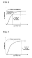
- the relative humidity is a factor that changes the lower limit of illumination for curing ink, as shown in Fig. 2b .
- ambient temperature measuring device 71 and humidity measuring device 72 known sensors in a prior art can be employed.
- a controller 8 is connected to the above-described carriage driving device 2a, conveying device 11, input device 12, recording heads 3a to 3d, irradiation device 4, temperature controller 4c, maintenance unit 6, medium temperature measuring device 13, ambient temperature measuring device, humidity measuring device 72, illumination measuring device 70, and the like.
- the controller 8 is constituted with a CPU, RAM, ROM and the like, which are not shown, and has a storage section 80 and calculating section 82.
- the storage diction 80 stores a table 81 (refer to Fig. 4 ) that indicates the relationships between the lower limit of illumination for curing that allows curing of ink, and the kind of a recording medium K, temperature of the recording medium K, ambient temperature, relative humidity, and resolution of an output image.
- the calculating section 82 performs computation to calculate the resolution of an output image and the like.
- the resolution of an output image is a factor that changes the lower limit of illumination for curing ink.
- the higher the resolution of an output image the smaller the ink amount per dot and the greater the ratio of the surface area to the volume of ink. Consequently, the water contained in the atmosphere enters ink more easily, and it becomes more difficult for the ink to be cured, which makes the lower limit of illumination for curing higher.
- the calculating section 82 calculates the lower limit of illumination for curing ink, based on information transmitted from the input device 12, measured results by the medium temperature measuring devise 13, ambient temperature measuring device 71 and humidity measuring device 72, and the resolution of an output image. More concretely, the calculating section 82 calculates the lower limit of illumination for curing by the use of the table 81 in the storage section 80.
- the above described controller 8 controls respective sections of the inkjet recording apparatus 1.
- the controller 8 controls the carriage driving device 2a to move the recording heads 3a to 3d and the irradiation devices 4, 4 in the scanning direction x. Further, the controller 8 controls the conveying device 11 to intermittently convey the recording medium K. Still further, the controller 8 controls the maintenance unit 6 to perform maintenance of the recording heads 3a to 3d.
- the controller 8 controls the recording heads 3a to 3d to jet ink. More specifically, the controller 8 controls the recording heads 3a to 3d to turn into the state that allows the recording heads 3a to 3d to perform image recording such as to jet ink, based on image data, when two illuminations, which are measured by the illumination measuring device 70 at a predetermined time interval after a start of lighting of the irradiation devices 4,4, are respectively higher than or equal to the lower limit of illumination for curing ink.
- controller 8 controls the irradiation devices 4,4 to irradiate UV light to cure ink on the surface of the recording medium K.
- the ink used in the present embodiment is UV-curable ink that is cured by irradiation of UV light, and contains at least a polymerizable compound (which may be a known polymerizable compound), photo-initiator and coloring material, as major components.
- a polymerizable compound which may be a known polymerizable compound
- photo-initiator and coloring material as major components.
- UV curable inks as described above, can be briefly categorized, in terms of polymerizable compounds, into radical-polymerization inks containing a radical-polymerizable compound and cation-polymerization inks containing a cation-polymerizable compound, both of which can be applied as ink to be used in the present embodiment.
- cation-curable inks are less or not inhibited by oxygen from polymerization, and accordingly more sensitive to UV light. Consequently, cation-curable inks are excellent in functionality and versatility.
- the recording medium used in the present embodiment it is possible to employ a medium made of a material, such as a plain paper applied to a common inkjet recording apparatus, recycled paper, glossy paper and other various papers, various fabrics, various nonwoven fabrics, resins, metals, glasses, foamed films and the like.
- a roll form, cut-sheet form, plate form, and the like can be applied as the form of the recording medium.
- the recording medium used in the present embodiment it is possible to apply known opaque recording mediums including various papers of which surface is coated with a resin, films containing a pigment, foamed films, and the like.
- the irradiation devices 4,4 start lighting and the temperature controller 4c maintains the temperature of the metal cap of each UV light source 4a higher than the temperature for the state of stable irradiation. In this way, as shown in Fig. 5 , the increasing rate of the illumination by the irradiation devices 4,4 is greater, compared with a case where the temperature of the metal caps is not controlled.
- the carriage 2 is reciprocally moved such that the irradiation devices 4,4 alternately face the illumination measuring device 70 twice respectively, and the illumination measuring device 70 facing the irradiation devices 4 measures the illumination.
- illuminations by the irradiation devices 4,4 are measured twice for each at a predetermined interval.
- the medium temperature measuring device 13, ambient temperature measuring device 71 and humidity measuring device 72 measure the temperatures and relative humidity.
- the information is transmitted from the input device 12 to the controller 8.
- controller 8 calculates the resolution of an output image, based on image data.
- the controller 8 calculates the lower limit of illumination for curing ink, based on measured results by the illumination measuring device 70, medium temperature measuring device 13, ambient temperature measuring device 71 and humidity measuring device 72, information transmitted from the input device 12, the resolution of an output image, and the table 81 in the storage section 80. In such a manner, the controller 8 calculates the lower limit of illumination for curing, based on measured results by the illumination measuring device 70, medium temperature measuring device 13, ambient temperature measuring device 71 and humidity measuring device 72, information transmitted from the input device 12, the resolution of an output image. Accordingly, an accurate lower limit of illumination for curing can be calculated regardless of changes in the temperatures, humidity and resolution. Further, since the controller 8 calculates the lower limit of illumination for curing ink, using the table 81, calculation of the lower limit of illumination for curing is easier than a case of calculating it, using mathematical expressions or the like.
- the controller 8 determines whether illuminations measured twice for the respective irradiation devices 4,4 are respectively higher than or equal to the lower limit of illumination for curing.
- the controller 8 makes the recording heads 3a to 3d in a state that allows them to perform image recording.
- the inkjet recording apparatus 1 turns into the state allowing image recording, earlier than a case of a prior art (refer to Fig. 7 ) where the recording heads 3a to 3d do not turn into the state allowing image recording until the illumination reaches the stable illumination.
- the carriage 2 and the illumination measuring device 70 collaborate with each other to repeat measuring illumination for the respective irradiation devices 4,4 until illuminations measured twice for the respective irradiation devices 4,4 respectively become higher than or equal to the lower limit of illumination for curing.
- the recording heads 3a to 3d turn into the state allowing image recording, with unstable illumination by the irradiation devices 4,4 higher than or equal to the lower limit of illumination for curing or with illumination by either irradiation device 4 lower than the lower limit of illumination for curing.
- the carriage 2 scans just above the recording medium K to one side in the scanning direction X.
- the recording heads 3a to 3d and irradiation devices 4,4 scan with the carriage 2, to record an image during this scanning.
- the recording heads 3a to 3d jet ink, and the irradiation device 4 on the trailing side from the recording heads 3a to 3d, namely, on the other side irradiates UV light onto the ink on the surface of the recording medium K.
- the temperature controller 4c maintains the temperature of the metal cap section of the UV light source 4a at the temperature for the state of stable illumination, fluctuation in illumination is inhibited.
- illumination by the irradiation devices 4,4 is higher or equal to the lower limit of illumination for curing ink, ink having landed on the recording medium K is securely cured by UV light and fixed to the surface of the recording medium K.
- the carriage 2 scans just above the recording medium K in the scanning direction, and the recording heads 3a to 3d and the irradiation devices 4,4 perform image recording during this scanning.
- the conveying device 11 conveys the recording medium K in the conveying direction Y.
- the inkjet recording apparatus 1 repeats the respective operations described above, thus sequentially recording desired images, formed of plural dots in respective process-colors, on the surface of the recording medium K.
- the irradiation devices 4,4 are turned off during the following maintenance operations.
- the carriage 2 moves to the maintenance area F.
- the cap members 61 rise and come into contact with the jetting faces 30 of the recording heads 3a to 3d.
- the suction pump 62 is driven to suck ink from inside the ink jetting openings of the recording heads 3a to 3d together with foreign matters and dispose the ink into the waste ink tank 63. In such a manner, clogging of the ink jetting openings of the recording heads 3a to 3d is avoided.
- the inkjet recording apparatus 1 in accordance with the present embodiment, it is possible to turn the inkjet recording apparatus 1 into a state that allows image recording earlier than a case of a prior art, and thereby the efficiency of image recording is improved.
- ink having landed on the recording medium K can be securely cured by light of illumination higher than the lower limit of illumination for curing ink, blurring of uncured ink can be prevented. Accordingly, deterioration in image quality can be prevented, compared with a case of a prior art.
- the illuminations by the irradiation devices 4,4 are unstably higher than or equal to the lower limit of illumination for curing, or in a case where illumination by either irradiation device 4 is lower than the lower limit of illumination for curing, it is possible to prevent a start of image recording. Accordingly, the illuminations by lights irradiated onto ink on the recording medium K can be securely made higher than the lower limit for curing. Thus, it is possible to securely cure ink on the recording medium K.
- the controller 8 compares the illuminations by the irradiation devices 4,4 with the lower limit of illumination for curing at a start-up or at the time of termination of maintenance, the controller 8 may properly make the comparison also during image recording.
- the irradiation devices 4,4 may continue irradiation for a low illumination, and also may continue irradiation for the same illumination as that during image recording. Also in these cases, it is preferable that the recording heads 3a to 3d are turned into the state allowing image recording after the controller 8 confirms that illuminations by the irradiation devices 4,4 are higher than or equal to the lower limit for curing after maintenance.
- the controller 8 may turns the recording heads 3a to 3d into the state allowing image recording when illuminations measured by the illumination measuring device 70 are higher than or equal to the lower limit of illumination for curing. In this case, for example, even during maintenance, jetting of ink can be controlled, depending on the measured illuminations.
- the humidity measuring device 72 may measure the absolute humidity.
- the table 81 stores the relationships between the lower limit of illumination for curing ink, and the kind of the recording medium K, temperature of the recording medium K, ambient temperature, absolute humidity and resolution of the output image.
- an illumination measuring device 70 may be arranged on each side of the cap members 61.
- the illumination measuring devices 70 preferably face the irradiation devices 4,4 when the recording heads 3a to 3d face the cap members 61.
- the carriage 2 does not need to reciprocally move to make the irradiation devices 4,4 face the illumination measuring devices 70, which allows simplification of the control of the carriage driving device 2a.
- the metal section of each UV light source 4a is connected with the temperature controller 4c
- the metal cap section may be connected with a power controller that controls the power to be applied to the metal cap section. It is preferable that this power controller maintains a power for the state of stable illumination when the irradiation devices 4 have reached the state of stable illumination, and applies a power, which is higher than the power for the state of stable illumination, to the metal cap section at a start of lighting of the irradiation devices 4 and at the time of switching to a higher illumination.
Abstract
Description
- The present invention relates to an inkjet recording apparatus that records an image on a recording medium.
- As apparatuses that record images even on recording mediums which absorb little ink, photo-curing inkjet type inkjet recording apparatuses are used. A photo-curing inkjet type recording apparatus jets photo-curable ink from a recording head/heads onto the surface of a recording medium such that the ink lands on the recording medium, and then irradiates light from an irradiation device/devices, such as a mercury lamp/lamps, so as to fix the ink on the surface of the recording medium (for example, refer to
Patent Documents 1 to 3). - However, as the illumination is unstable just after a start of lighting of an irradiation device, it is possible that ink is not cured even when image recording is stared. Accordingly, in a viewpoint of curing ink securely, an inkjet recording apparatus in a prior art does not start image recording until the illumination reaches a stable illumination after a start of lighting, as shown in
Fig. 7 . - Patent Document 1:
- Japanese Patent Application Publication TOKKAI No.
2002-137375 - Patent Document 2:
- Japanese Patent Application Publication TOKKAI No.
2003-145725 - Patent Document 3:
- Japanese Patent Application Publication TOKKAI No.
2004-1326 -
JP 2004-188929 A - However, in general, illumination required for curing ink, namely, the lower limit of illumination for curing, is lower than the stable illumination of an irradiation device. Accordingly, if image recording is not performed until the illumination reaches the stable illumination, start of image recording is wastefully delayed, resulting in inefficiency.
- An aim of the present invention is to provide an inkjet recording apparatus that improves the efficiency of image recording.
- According to the present invention, there is provided an inkjet recording apparatus as defined in the independent claim.
- According to the present invention, since a recording head is in a state that allows the recording head to perform image recording when the illumination measured by the illumination measuring device is higher than or equal to the lower limit of illumination for curing ink, image recording starts earlier, compared with a case of a prior art where a recording head does not turn into a state that allows the recording head to perform image recording until the illumination reaches a stable illumination. Thus, the efficiency of image recording can be improved.
- Further, since light that causes an illumination higher than or equal to the lower limit of illumination for curing is irradiated onto ink having landed on a recording medium, the ink can be securely cured. Accordingly, blurring by uncured ink or the like can be prevented, and thus it is possible to prevent deterioration of image quality, compared with cases of a prior art.
- According to the present invention, since a recording head turns into a state that allows the recording head to jet ink when two measured illuminations measured by an illumination measuring device are respectively higher than or equal to a lower limit of illumination for curing, it is possible to prevent a start of image recording when illumination by an irradiation device is unstably higher than or equal to a lower limit of illumination for curing, which may occur, for example, just after a start of lighting or switching the output. Thus, it is possible to control the illumination caused by light that is irradiated onto ink on a recording medium to be securely higher than or equal to the lower limit of illumination for curing. Accordingly, ink can be securely cured.
- The inkjet recording apparatus may include a plurality of said irradiation devices, wherein the controller controls the recording head to be in a state that allows the recording head to jet ink, when two illuminations measured by the illumination measuring device at a predetermined time interval are respectively higher than or equal to the lower limit of illumination for curing, with respect to each of the irradiation devices.
- According to the above structure, since a recording head turns into a state that allows the recording head to jet ink, when two measured illuminations measured by an illumination measuring device are respectively higher than or equal to a lower limit of illumination for curing, with respect to each of the irradiation devices, it is possible to prevent a start of image recording when illumination by an irradiation device is unstably higher than or equal to a lower limit of illumination for curing, which may occur, for example, just after a start of lighting or switching the output. Thus, it is possible to control the illumination by light that is irradiated onto ink on a recording medium to be securely higher than or equal to a lower limit of illumination for curing. Accordingly, ink can be securely cured.
- The inkjet recording apparatus may include at least one of:
- an input device via which an operator inputs a kind of a recording medium;
- a first temperature measuring device that measures a temperature of a recording medium;
- a second temperature measuring device that measures an ambient temperature;
- a humidity measuring device that measures a humidity; and
- a calculating section that calculates resolution of an output image,
- wherein the controller calculates the lower limit of illumination for curing, based on at least one of the kind of a recording medium, temperature of the recording medium, ambient temperature, humidity and resolution of an output image.
- Herein, the lower limit of illumination for curing ink changes depending on the kind of the recording medium, temperature of the recording medium, ambient temperature, humidity, resolution of the output image, and the like. For example, as the water containing rate is greater, it is more difficult to cure ink, and accordingly, the lower limit of illumination for curing is higher. Further, as the temperature of the recording medium and ambient temperature are higher, ink is warmed more in advance prior to irradiation of light, and accordingly the lower limit of illumination for curing is lower. Still further, as the humidity is higher, it is more difficult that the solvent of ink evaporates, and accordingly the lower limit of illumination for curing is higher. Yet further, as the resolution of an output image is higher, the ink amount per dot is smaller, and accordingly the ratio of the surface area to the volume of ink is greater. This results in that water in the atmosphere gets into ink more easily, and ink is more difficult to be cured, and accordingly the lower limit of illumination for curing becomes higher.
- According to the above structure, since the controller calculates the lower limit of illumination for curing, based on at least one of the kind of a recording medium, temperature of the recording medium, ambient temperature, humidity and resolution of an output image, it is possible to calculate an accurate lower limit of illumination for curing, regardless of changes in the kind and temperature of the recording medium, humidity, and resolution. Thus, it is possible to securely cure ink.
- The first temperature measuring device may measure a temperature of a platen that supports the recording medium, for the temperature of the recording medium.
- According to the above structure, since the first temperature measuring device measures the temperature of a platen that supports the recording medium, for the temperature of the recording medium, it is possible to prevent occurrence of a failure of the first temperature measuring device, which could be caused by friction with the conveyed recording medium, compared with a case of directly measuring the temperature of a recording medium.
- The inkjet recording apparatus may include a storage section that stores a table indicating a relationship between the lower limit of illumination for curing ink and at least one of the kind of a recording medium, temperature of the recording medium, ambient temperature, humidity and resolution of an output image,
wherein the controller calculates the lower limit of illumination for curing ink, using the table. - According to the above structure, since the controller calculates the lower limit of illumination for curing, using the table, it is possible to calculate the lower limit of illumination for curing more easily, compared with a case of calculating it, using a mathematical expression or the like.
- The recording head may jet an ink of a cation-polymerization type.
- According to the above structure, the same effect as above can be obtained.
- The controller may control the recording head to be in a state that prohibits the recording head to jet ink, when at least one of the two illuminations measured by the illumination measuring device is lower than the lower limit of illumination for curing ink.
- According to the above structure, it is possible to prevent that the recording head jets ink in a state where light irradiated by the irradiation device causes an illumination that is lower than the lower limit of illumination for curing ink and the ink flows on the recording medium without being cured.
- Optionally, when at least one of the two illuminations measured by the illumination measuring device is lower than the lower limit of illumination for curing ink, for a time longer than or equal to a predetermined time period, the controller performs an alarm function.
- According to the above structure, it is possible to prevent leaving a state where image recording is not performed or ink is not jetted because light irradiated from the irradiation device causes an illumination that is lower than the lower limit of illumination for curing while an operator is unaware of the state.
- Optionally, during when jetted ink is irradiated, the controller turns the recording head into a state that prohibits the recording head to jet ink when at least one of the two illuminations measured by the illumination measuring device has become lower than the lower limit of illumination for curing ink, and performs an alarm function.
- According to the above structure, it is possible to automatically stop image recording or jetting of ink immediately when illumination by light irradiated from the irradiation device decreases and becomes lower than the lower limit of illumination for curing ink during image recording and the state changes such that ink is not cured, and to alarm the operator of the fact.
- According to the structure of the independent claim, image recording starts earlier than a case of a prior art where a recording head does not turn into a state that allows the recording head to jet ink until the illumination reaches a stable illumination. Accordingly, the efficiency of image recording can be improved.
- Furthermore, it is possible to securely cure ink because the illumination by light irradiated from the irradiation device onto ink on the recording medium is securely made higher than or equal to the lower limit of illumination for curing.
- According to the structure of claim 3, it is possible to calculate an accurate lower limit of illumination for curing regardless of a change in the kind and temperature of a recording medium, humidity, and resolution. Accordingly, ink can be securely cured.
- According to the structure of
claim 4, it is possible to prevent occurrence of a failure of the first temperature measuring device, which could be caused by friction with the conveyed recording medium, compared with a case of directly measuring the temperature of the recording medium. - According to the structure of claim 5, it is possible to easily calculate the lower limit of illumination for curing.
- According to the structure of claim 7, it is possible to prevent that the recording head jets ink in a state where light irradiated by the irradiation device causes an illumination that is lower than the lower limit of illumination for curing ink and the ink flows on the recording medium without being cured.
- According to the structure of
claim 8 or 9, it is possible to prevent leaving a state where image recording is not performed or ink is not jetted because light irradiated from the irradiation device causes illumination that is lower than the lower limit of illumination for curing ink while an operator is unaware of the state, or to prevent that jetting of ink continues and ink flows when illumination by light irradiated from the irradiation device has become lower than the lowest limit of illumination for curing ink during image recording and the state has changed such that ink is not cured. The operator is alarmed of the fact. -
Fig. 1 is a front view of a schematic structure of an inkjet recording apparatus in accordance with the invention; -
Fig. 2 is a diagram showing the lower limit of illumination for curing ink; -
Fig. 3 is a block diagram showing a schematic structure of the inkjet recording apparatus in accordance with the invention; -
Fig. 4 is a diagram showing an example of a table regarding the lower limit of illumination for curing ink; -
Fig. 5 is a diagram showing changes in illumination after a start of lighting of an irradiation device; -
Fig. 6 is a diagram showing image recording start timing of the inkjet recording apparatus in accordance with the invention; and -
Fig. 7 is a diagram showing image recording start timing of an inkjet recording apparatus in a prior art. -
- 1
- inkjet recording apparatus
- 3a to 3d
- recording head
- 4
- irradiation device
- 8
- controller
- 10
- platen
- 12
- input device
- 13
- medium temperature measuring device (first temperature measuring device)
- 70
- illumination measuring device
- 71
- ambient temperature measuring device (second temperature measuring device)
- 72
- humidity measuring device
- 80
- storage section
- 81
- table
- 82
- calculating section
- K
- recording mediu8m
- An embodiment in accordance with the invention will be described below, referring to the drawings. Herein, the present embodiment will be described for a case where the inkjet recording apparatus is a serial head type.
-
Fig. 1 is a side view showing a schematic structure of an inkjet recording apparatus in accordance with the present invention. - As shown in the figure, the
inkjet recording apparatus 1 is provided with aplaten 10 that is arranged in a recording area E and supports a recording medium K planarly on the back side. The recording medium K supported by theplaten 10 is conveyed by a conveying device 11 (refer toFig, 3 ), in conveying direction Y (the front and back direction with respect toFig. 1 ). An operator can input the kind of a recording medium K supported by theplaten 10 via an input device 12 (refer toFig. 3 ). Herein, the kind of the recording medium K is a factor that changes the lower limit of illumination for curing ink. For example, the higher the water containing ratio of the recording medium K, the more difficult for ink to be cured on the surface of the recording medium K, and accordingly, the higher the lower limit of illumination for curing ink. Further, with a recording medium K, such as paper, that contains calcium carbonate, the lower limit of illumination for curing is higher because polymerization is inhibited. - A medium temperature measuring device 13 (refer to
Fig 3 ) as a first temperature measuring device in accordance with the present invention is provided on the top surface of theplaten 10. The mediumtemperature measuring device 13 measures the temperature of the recording medium K, and measures the temperature of the top surface of theplaten 10 for the temperature of the recording medium K. Herein, as shown inFig. 2a , the temperature of the recoding medium K is a factor that changes the lower limit of illumination for curing ink. As this temperature is higher, ink is warmed more in advance prior to irradiation by light from anirradiation device 4, and accordingly, the lower limit of illumination for curing ink is lower. As the mediumtemperature measuring device 13, a known temperature sensor in a prior art can be employed. - A
carriage rail 14 is arranged above theplaten 10, extending in the scanning direction X. Acarriage 2 is provided on thecarriage rail 14. - The
carriage 2 is driven by acarriage driving device 2a (refer toFig. 3 ) to be moved in the scanning direction X from the recording area E to the maintenance area F. A plurality of recording heads 3a to 3d are mounted on thecarriage 2, aligned along the scanning direction X. - The recording heads 3a to 3d jet photo-curable ink, UV curable-ink in the present embodiment, from a plurality of ink jetting openings (not shown) arranged through the jetting faces 30 onto the recording medium K. Each of the inkjet openings is arranged such as to individually jet ink as liquid droplets with operation of a piezo-element or heating element, for example. In the present embodiment, the
recording head 3a jets black (K) ink,recording head 3b jets cyan (C) ink,recording head 3c jets magenta (M) ink, andrecording head 3d jets yellow (Y) ink. - The recording heads 3a to 3d are respectively connected to
ink tanks 31 storing ink in corresponding colors throughink supply tubes 32. Theseink tanks 31 andink supply tubes 32 supply ink to the recording heads 3a to 3d. - Further,
irradiation devices carriage 2 in the scanning direction X so as to be moved in the scanning direction X with thecarriage 2. - Each
irradiation device 4 is provided with aUV light source 4a inside acover member 4b in a recessed shape being open downward. - Each
UV light source 4a radially irradiates UV light. As theUV light source 4a, it is possible to employ, for example, a high-pressure mercury lamp, low-pressure mercury lamp, metal-halide lamp, black light, hot-cathode tube, cold-cathode tube, LED (Light Emitting Diode), electrodeless lamp, excimer lamp, etc. - The metal cap section (not shown) of the UV
light source 4a is connected with atemperature controller 4c (refer toFig. 3 ). - When the
irradiation devices controller 4c maintains the metal cap sections at the temperature for the state of stable illumination, for example, 50 to 60 °C. Further, at a start of lighting of theirradiation devices temperature controller 4c maintains the metal cap sections at atemperature 10 to 20 °C higher than the temperature for the state of stable illumination. - Still further, as shown in
Fig. 1 , amaintenance unit 6 is arranged in the maintenance area F beside theplaten 10. - The
maintenance unit 6 performs maintenance of the recording heads 3a to 3d, and shields the jetting faces 30 of the recording heads 3a to 3d in a waiting state from UV light. Themaintenance unit 6 is provided withcap members 61 which are movable up and down. - The
cap members 61 cover the jetting faces 30 of the recording heads 3a to 3d, and are disposed corresponding to the array of the recording heads 3a to 3d so as to be able to cover the jetting faces 30 of the fourrecording heads 4a to 4d at the same time. - The
cap members 61 are communicated with a waste-ink tank 63 through asuction pump 62. Thesuction pump 62 includes a cylinder pump, tube pump, or the like, and generates a suction force to suck ink in the recording heads 3a to 3d from the ink jetting openings (not shown) along with foreign matter in a state where thecap members 61 cover the jetting faces 30. - Beside the
cap members 61, there are arranged anillumination measuring device 70, ambient temperature measuring device 71 (refer toFig. 3 ), and humidity measuring device 72 (refer toFig. 3 ). - The
illumination measuring device 70 measures the illumination by light irradiated from theirradiation device 4. - The ambient
temperature measuring device 71 is the second temperature measuring device in accordance with the invention, and measures the ambient temperature inside theinkjet recording apparatus 1. Herein, the ambient temperature is a factor that changes the lower limit of illumination for curing ink. As the temperature of the ambient temperature is higher, ink is warmed more in advance prior to irradiation of light, and accordingly the lower limit of illumination for curing is lower. - The
humidity measuring device 72 measures the relative humidity inside theinkjet recording apparatus 1. Herein, the relative humidity is a factor that changes the lower limit of illumination for curing ink, as shown inFig. 2b . The higher the relative humidity, the more difficult for the solvent of ink to evaporate, and accordingly the lower limit of illumination for curing ink is higher. - For the
illumination measuring device 70, ambienttemperature measuring device 71 andhumidity measuring device 72, known sensors in a prior art can be employed. - As shown in
Fig. 3 , acontroller 8 is connected to the above-describedcarriage driving device 2a, conveyingdevice 11, input device 12, recording heads 3a to 3d,irradiation device 4,temperature controller 4c,maintenance unit 6, mediumtemperature measuring device 13, ambient temperature measuring device,humidity measuring device 72,illumination measuring device 70, and the like. - The
controller 8 is constituted with a CPU, RAM, ROM and the like, which are not shown, and has astorage section 80 and calculatingsection 82. - The
storage diction 80 stores a table 81 (refer toFig. 4 ) that indicates the relationships between the lower limit of illumination for curing that allows curing of ink, and the kind of a recording medium K, temperature of the recording medium K, ambient temperature, relative humidity, and resolution of an output image. - The calculating
section 82 performs computation to calculate the resolution of an output image and the like. Herein, as shown inFig. 2c , the resolution of an output image is a factor that changes the lower limit of illumination for curing ink. The higher the resolution of an output image, the smaller the ink amount per dot and the greater the ratio of the surface area to the volume of ink. Consequently, the water contained in the atmosphere enters ink more easily, and it becomes more difficult for the ink to be cured, which makes the lower limit of illumination for curing higher. - The calculating
section 82 calculates the lower limit of illumination for curing ink, based on information transmitted from the input device 12, measured results by the medium temperature measuring devise 13, ambienttemperature measuring device 71 andhumidity measuring device 72, and the resolution of an output image. More concretely, the calculatingsection 82 calculates the lower limit of illumination for curing by the use of the table 81 in thestorage section 80. - The above described
controller 8 controls respective sections of theinkjet recording apparatus 1. - Specifically, the
controller 8 controls thecarriage driving device 2a to move the recording heads 3a to 3d and theirradiation devices controller 8 controls the conveyingdevice 11 to intermittently convey the recording medium K. Still further, thecontroller 8 controls themaintenance unit 6 to perform maintenance of the recording heads 3a to 3d. - Yet further, the
controller 8 controls the recording heads 3a to 3d to jet ink. More specifically, thecontroller 8 controls the recording heads 3a to 3d to turn into the state that allows the recording heads 3a to 3d to perform image recording such as to jet ink, based on image data, when two illuminations, which are measured by theillumination measuring device 70 at a predetermined time interval after a start of lighting of theirradiation devices - Further, the
controller 8 controls theirradiation devices - Now, "ink" used in the present embodiment will be described.
- The ink used in the present embodiment is UV-curable ink that is cured by irradiation of UV light, and contains at least a polymerizable compound (which may be a known polymerizable compound), photo-initiator and coloring material, as major components.
- UV curable inks, as described above, can be briefly categorized, in terms of polymerizable compounds, into radical-polymerization inks containing a radical-polymerizable compound and cation-polymerization inks containing a cation-polymerizable compound, both of which can be applied as ink to be used in the present embodiment. However, cation-curable inks are less or not inhibited by oxygen from polymerization, and accordingly more sensitive to UV light. Consequently, cation-curable inks are excellent in functionality and versatility.
- Now, "recording medium" used in the present embodiment will be described.
- For the recording medium used in the present embodiment, it is possible to employ a medium made of a material, such as a plain paper applied to a common inkjet recording apparatus, recycled paper, glossy paper and other various papers, various fabrics, various nonwoven fabrics, resins, metals, glasses, foamed films and the like. As the form of the recording medium, a roll form, cut-sheet form, plate form, and the like can be applied.
- Further, for the recording medium used in the present embodiment, it is possible to apply known opaque recording mediums including various papers of which surface is coated with a resin, films containing a pigment, foamed films, and the like.
- Now, operations of the
inkjet recording apparatus 1 at the time of start-up and at the time of termination of later-described maintenance will be described. - The
irradiation devices temperature controller 4c maintains the temperature of the metal cap of eachUV light source 4a higher than the temperature for the state of stable irradiation. In this way, as shown inFig. 5 , the increasing rate of the illumination by theirradiation devices - Next, the
carriage 2 is reciprocally moved such that theirradiation devices illumination measuring device 70 twice respectively, and theillumination measuring device 70 facing theirradiation devices 4 measures the illumination. Thus, illuminations by theirradiation devices - The medium
temperature measuring device 13, ambienttemperature measuring device 71 andhumidity measuring device 72 measure the temperatures and relative humidity. - Further, when the operator inputs a kind of a recording medium via the input device 12, the information is transmitted from the input device 12 to the
controller 8. - Still further, the
controller 8 calculates the resolution of an output image, based on image data. - Next, the
controller 8 calculates the lower limit of illumination for curing ink, based on measured results by theillumination measuring device 70, mediumtemperature measuring device 13, ambienttemperature measuring device 71 andhumidity measuring device 72, information transmitted from the input device 12, the resolution of an output image, and the table 81 in thestorage section 80. In such a manner, thecontroller 8 calculates the lower limit of illumination for curing, based on measured results by theillumination measuring device 70, mediumtemperature measuring device 13, ambienttemperature measuring device 71 andhumidity measuring device 72, information transmitted from the input device 12, the resolution of an output image. Accordingly, an accurate lower limit of illumination for curing can be calculated regardless of changes in the temperatures, humidity and resolution. Further, since thecontroller 8 calculates the lower limit of illumination for curing ink, using the table 81, calculation of the lower limit of illumination for curing is easier than a case of calculating it, using mathematical expressions or the like. - Next, the
controller 8 determines whether illuminations measured twice for therespective irradiation devices - Then, when the respective illuminations are higher than or equal to the lower limit of illumination for curing, the
controller 8 makes the recording heads 3a to 3d in a state that allows them to perform image recording. In such a manner, as shown inFig. 6 , theinkjet recording apparatus 1 turns into the state allowing image recording, earlier than a case of a prior art (refer toFig. 7 ) where the recording heads 3a to 3d do not turn into the state allowing image recording until the illumination reaches the stable illumination. - On the other hand, when even one illumination is lower than the lower limit of illumination for curing, the
carriage 2 and theillumination measuring device 70 collaborate with each other to repeat measuring illumination for therespective irradiation devices respective irradiation devices irradiation devices irradiation device 4 lower than the lower limit of illumination for curing. - Now, operation of the
inkjet recording apparatus 1 during image recording will be described. - First, while conveyance of a recording medium K by the conveying
device 11 is stopped, thecarriage 2 scans just above the recording medium K to one side in the scanning direction X. Thus, the recording heads 3a to 3d andirradiation devices carriage 2, to record an image during this scanning. Specifically, the recording heads 3a to 3d jet ink, and theirradiation device 4 on the trailing side from the recording heads 3a to 3d, namely, on the other side, irradiates UV light onto the ink on the surface of the recording medium K. Herein, since thetemperature controller 4c maintains the temperature of the metal cap section of the UVlight source 4a at the temperature for the state of stable illumination, fluctuation in illumination is inhibited. And, as illumination by theirradiation devices - Next, in the state where conveying of the recording medium K by the conveying
device 11 is stopped after the conveyingdevice 11 has conveyed the recording medium K along the conveying direction Y, thecarriage 2 scans just above the recording medium K in the scanning direction, and the recording heads 3a to 3d and theirradiation devices - Next, the conveying
device 11 conveys the recording medium K in the conveying direction Y. - Thereafter, the
inkjet recording apparatus 1 repeats the respective operations described above, thus sequentially recording desired images, formed of plural dots in respective process-colors, on the surface of the recording medium K. - Now, the operation of the
inkjet recording apparatus 1 during maintenance of the recording heads will be described. Theirradiation devices - First, the
carriage 2 moves to the maintenance area F. - Then, the
cap members 61 rise and come into contact with the jetting faces 30 of the recording heads 3a to 3d. When thecap members 61 cover the jetting faces 30 of the recording heads 3a to 3d, thesuction pump 62 is driven to suck ink from inside the ink jetting openings of the recording heads 3a to 3d together with foreign matters and dispose the ink into thewaste ink tank 63. In such a manner, clogging of the ink jetting openings of the recording heads 3a to 3d is avoided. - Then, the
cap members 61 move downward and the maintenance operation is terminated. - As has been described above, according to the
inkjet recording apparatus 1 in accordance with the present embodiment, it is possible to turn theinkjet recording apparatus 1 into a state that allows image recording earlier than a case of a prior art, and thereby the efficiency of image recording is improved. - Further, since ink having landed on the recording medium K can be securely cured by light of illumination higher than the lower limit of illumination for curing ink, blurring of uncured ink can be prevented. Accordingly, deterioration in image quality can be prevented, compared with a case of a prior art.
- Still further, in a case where the illuminations by the
irradiation devices irradiation device 4 is lower than the lower limit of illumination for curing, it is possible to prevent a start of image recording. Accordingly, the illuminations by lights irradiated onto ink on the recording medium K can be securely made higher than the lower limit for curing. Thus, it is possible to securely cure ink on the recording medium K. - Although in the present embodiment, it has been described that the
controller 8 compares the illuminations by theirradiation devices controller 8 may properly make the comparison also during image recording. - Further, although it has been described that the
irradiation devices irradiation devices controller 8 confirms that illuminations by theirradiation devices - Still further, although it has been described that the
controller 8 turns the recording heads 3a to 3d into the state allowing image recording when illuminations measured by theillumination measuring device 70 are higher than or equal to the lower limit of illumination for curing, thecontroller 8 may turns the recording heads 3a to 3d into the state allowing ink jetting. In this case, for example, even during maintenance, jetting of ink can be controlled, depending on the measured illuminations. - Yet further, although it has been described that the
humidity measuring device 72 measures the relative humidity, thehumidity measuring device 72 may measure the absolute humidity. In this case, the table 81 stores the relationships between the lower limit of illumination for curing ink, and the kind of the recording medium K, temperature of the recording medium K, ambient temperature, absolute humidity and resolution of the output image. - Further, although it has been described that only a single
illumination measuring device 70 is arranged beside thecap members 61, anillumination measuring device 70 may be arranged on each side of thecap members 61. In this case, theillumination measuring devices 70 preferably face theirradiation devices cap members 61. Thus, thecarriage 2 does not need to reciprocally move to make theirradiation devices illumination measuring devices 70, which allows simplification of the control of thecarriage driving device 2a. - Still further, although it has been described that the metal section of each
UV light source 4a is connected with thetemperature controller 4c, the metal cap section may be connected with a power controller that controls the power to be applied to the metal cap section. It is preferable that this power controller maintains a power for the state of stable illumination when theirradiation devices 4 have reached the state of stable illumination, and applies a power, which is higher than the power for the state of stable illumination, to the metal cap section at a start of lighting of theirradiation devices 4 and at the time of switching to a higher illumination.
Claims (9)
- An inkjet recording apparatus (1), comprising:a recording head (3) that jets photo-curable ink onto a recording medium (K);at least one irradiation device (4) that irradiates light onto ink having landed on a surface of the recording medium;an illumination measuring device (70) that measures an illumination by light that is irradiated from the irradiation device; anda controller (8) that controls the recording head,characterized in that the controller controls the recording head to be in a state that allows the recording head to perform image recording, when two illuminations measured by the illumination measuring device at a predetermined time interval are respectively higher than or equal to the lower limit of illumination for curing.
- The inkjet recording apparatus of Claim 1, comprising a plurality of said irradiation devices, wherein the controller controls the recording head to be in a state that allows the recording head to perform image recording, when two illuminations measured by the illumination measuring device at a predetermined time interval are respectively higher than or equal to the lower limit of illumination for curing, with respect to each of the irradiation devices.
- The inkjet recording apparatus of claim 1 or 2, comprising at least one of:an input device (12) via which an operator inputs a kind of a recording medium;a first temperature measuring device (13) that measures a temperature of a recording medium;a second temperature measuring device (71) that measures an ambient temperature;a humidity measuring device (72) that measures a humidity; anda calculating section (82) that calculates resolution of an output image,wherein the controller calculates the lower limit of illumination for curing, based on at least one of the kind of a recording medium, temperature of the recording medium, ambient temperature, humidity and resolution of an output image.
- The inkjet recording apparatus of claim 3, wherein the first temperature measuring device measures a temperature of a platen that supports the recording medium, for the temperature of the recording medium.
- The inkjet recording apparatus of claim 3 or 4, comprising a storage section that stores a table indicating a relationship between the lower limit of illumination for curing and at least one of the kind of a recording medium, temperature of the recording medium, ambient temperature, humidity and resolution of an output image,
wherein the controller calculates the lower limit of illumination for curing, using the table. - The inkjet recording apparatus of any one of claims 1 to 5, wherein the recording head jets an ink of a cation-polymerization type.
- The inkjet recording apparatus of claim 1, wherein the controller controls the recording head to be in a state that prohibits the recording head to perform image recording, when at least one of the two illuminations measured by the illumination measuring device is lower than the lower limit of illumination for curing ink.
- The inkjet recording apparatus of claim 1, wherein when at least one of the two illuminations measured by the illumination measuring device is lower than the lower limit of illumination for curing ink, for a time longer than or equal to a predetermined time period, the controller performs an alarm function.
- The inkjet recording apparatus of claim 1, wherein during when jetted ink is irradiated, the controller turns the recording head into a state that prohibits the recording head to perform image recording when at least one of the two illuminations measured by the illumination measuring device has become lower than the lower limit of illumination for curing ink, and performs an alarm function.
Applications Claiming Priority (2)
| Application Number | Priority Date | Filing Date | Title |
|---|---|---|---|
| JP2004337630A JP2006142707A (en) | 2004-11-22 | 2004-11-22 | Inkjet recorder |
| PCT/JP2005/020909 WO2006054534A1 (en) | 2004-11-22 | 2005-11-15 | Inkjet recording device |
Publications (3)
| Publication Number | Publication Date |
|---|---|
| EP1815988A1 EP1815988A1 (en) | 2007-08-08 |
| EP1815988A4 EP1815988A4 (en) | 2010-11-24 |
| EP1815988B1 true EP1815988B1 (en) | 2012-03-21 |
Family
ID=36407077
Family Applications (1)
| Application Number | Title | Priority Date | Filing Date |
|---|---|---|---|
| EP20050807002 Active EP1815988B1 (en) | 2004-11-22 | 2005-11-15 | Inkjet recording device |
Country Status (4)
| Country | Link |
|---|---|
| US (1) | US20090147037A1 (en) |
| EP (1) | EP1815988B1 (en) |
| JP (1) | JP2006142707A (en) |
| WO (1) | WO2006054534A1 (en) |
Families Citing this family (5)
| Publication number | Priority date | Publication date | Assignee | Title |
|---|---|---|---|---|
| JP4802076B2 (en) * | 2006-09-29 | 2011-10-26 | 富士フイルム株式会社 | Active energy curable ink jet recording apparatus |
| JP5682750B2 (en) | 2010-03-30 | 2015-03-11 | セイコーエプソン株式会社 | Inkjet recording apparatus and inkjet recording method |
| JP5845633B2 (en) * | 2011-05-26 | 2016-01-20 | セイコーエプソン株式会社 | Droplet discharge device |
| JP2015160320A (en) * | 2014-02-26 | 2015-09-07 | セイコーエプソン株式会社 | Irradiation equipment and image recorder |
| JP6390407B2 (en) * | 2014-12-16 | 2018-09-19 | 富士ゼロックス株式会社 | Drying apparatus, image forming apparatus, and drying program |
Family Cites Families (6)
| Publication number | Priority date | Publication date | Assignee | Title |
|---|---|---|---|---|
| US7131722B2 (en) * | 2002-08-30 | 2006-11-07 | Konica Corporation | Ink jet printer and image recording method using a humidity detector to control the curing of an image |
| JP2004188924A (en) * | 2002-12-13 | 2004-07-08 | Konica Minolta Holdings Inc | Inkjet recording device |
| JP2004188929A (en) * | 2002-12-13 | 2004-07-08 | Konica Minolta Holdings Inc | Inkjet recording device |
| US20040145642A1 (en) * | 2003-01-17 | 2004-07-29 | Yoshihide Hoshino | Liquid jetting apparatus |
| US7152970B2 (en) * | 2003-03-12 | 2006-12-26 | Konica Minolta Holdings, Inc. | Image forming apparatus having a plurality of printing heads |
| US7140711B2 (en) * | 2003-07-21 | 2006-11-28 | 3M Innovative Properties Company | Method and apparatus for inkjet printing using radiation curable ink |
-
2004
- 2004-11-22 JP JP2004337630A patent/JP2006142707A/en active Pending
-
2005
- 2005-11-15 WO PCT/JP2005/020909 patent/WO2006054534A1/en active Application Filing
- 2005-11-15 EP EP20050807002 patent/EP1815988B1/en active Active
- 2005-11-15 US US11/719,494 patent/US20090147037A1/en not_active Abandoned
Also Published As
| Publication number | Publication date |
|---|---|
| US20090147037A1 (en) | 2009-06-11 |
| WO2006054534A1 (en) | 2006-05-26 |
| JP2006142707A (en) | 2006-06-08 |
| EP1815988A1 (en) | 2007-08-08 |
| EP1815988A4 (en) | 2010-11-24 |
Similar Documents
| Publication | Publication Date | Title |
|---|---|---|
| EP1627746B1 (en) | Printing device with radiation source | |
| EP2095966B1 (en) | Inkjet printer and printing method | |
| JP4649935B2 (en) | Inkjet printer | |
| EP1426191B1 (en) | Ink jet recording apparatus | |
| EP1815988B1 (en) | Inkjet recording device | |
| US7396103B2 (en) | Inkjet recording apparatus and method for maintenance of recording head | |
| JP2004338239A (en) | Ink jet recorder | |
| JP2006272853A (en) | Ink jet recorder | |
| JP2008105268A (en) | Inkjet image formation device with photocurable ink and inkjet image forming method | |
| JP2004291418A (en) | Image recording method and image recording apparatus | |
| JP2005104116A (en) | Inkjet printer | |
| JP2004195966A (en) | Inkjet recording device | |
| US7014285B2 (en) | Ink jet printer | |
| JP2006051773A (en) | Inkjet recorder | |
| JP2005238733A (en) | Ink-jet recording device | |
| JP2006159499A (en) | Inkjet recording device | |
| JP2005081577A (en) | Ink jet printer | |
| JP2005161757A (en) | Inkjet printer | |
| US20240092095A1 (en) | Method for enhancing adhesion of a uv curable ink | |
| JP2004188929A (en) | Inkjet recording device | |
| JP2004237602A (en) | Inkjet recorder | |
| JP2005246954A (en) | Inkjet printer | |
| JP4306239B2 (en) | Inkjet printer | |
| JP4345442B2 (en) | Inkjet printer | |
| JP2005074733A (en) | Inkjet recording apparatus |
Legal Events
| Date | Code | Title | Description |
|---|---|---|---|
| PUAI | Public reference made under article 153(3) epc to a published international application that has entered the european phase |
Free format text: ORIGINAL CODE: 0009012 |
|
| 17P | Request for examination filed |
Effective date: 20070518 |
|
| AK | Designated contracting states |
Kind code of ref document: A1 Designated state(s): DE GB |
|
| RBV | Designated contracting states (corrected) |
Designated state(s): DE GB |
|
| DAX | Request for extension of the european patent (deleted) | ||
| RAP1 | Party data changed (applicant data changed or rights of an application transferred) |
Owner name: KONICA MINOLTA MEDICAL & GRAPHIC, INC. |
|
| A4 | Supplementary search report drawn up and despatched |
Effective date: 20101026 |
|
| REG | Reference to a national code |
Ref country code: DE Ref legal event code: R079 Ref document number: 602005033302 Country of ref document: DE Free format text: PREVIOUS MAIN CLASS: B41J0002010000 Ipc: C09D0011100000 |
|
| GRAP | Despatch of communication of intention to grant a patent |
Free format text: ORIGINAL CODE: EPIDOSNIGR1 |
|
| RIC1 | Information provided on ipc code assigned before grant |
Ipc: B41J 11/00 20060101ALI20110928BHEP Ipc: C09D 11/10 20060101AFI20110928BHEP |
|
| GRAS | Grant fee paid |
Free format text: ORIGINAL CODE: EPIDOSNIGR3 |
|
| GRAA | (expected) grant |
Free format text: ORIGINAL CODE: 0009210 |
|
| AK | Designated contracting states |
Kind code of ref document: B1 Designated state(s): DE GB |
|
| REG | Reference to a national code |
Ref country code: GB Ref legal event code: FG4D |
|
| REG | Reference to a national code |
Ref country code: DE Ref legal event code: R096 Ref document number: 602005033302 Country of ref document: DE Effective date: 20120516 |
|
| PLBE | No opposition filed within time limit |
Free format text: ORIGINAL CODE: 0009261 |
|
| STAA | Information on the status of an ep patent application or granted ep patent |
Free format text: STATUS: NO OPPOSITION FILED WITHIN TIME LIMIT |
|
| 26N | No opposition filed |
Effective date: 20130102 |
|
| REG | Reference to a national code |
Ref country code: DE Ref legal event code: R097 Ref document number: 602005033302 Country of ref document: DE Effective date: 20130102 |
|
| P01 | Opt-out of the competence of the unified patent court (upc) registered |
Effective date: 20230510 |
|
| PGFP | Annual fee paid to national office [announced via postgrant information from national office to epo] |
Ref country code: GB Payment date: 20230921 Year of fee payment: 19 |
|
| PGFP | Annual fee paid to national office [announced via postgrant information from national office to epo] |
Ref country code: DE Payment date: 20230919 Year of fee payment: 19 |