EP1815928A1 - Cutting device and cutting method - Google Patents
Cutting device and cutting method Download PDFInfo
- Publication number
- EP1815928A1 EP1815928A1 EP05809653A EP05809653A EP1815928A1 EP 1815928 A1 EP1815928 A1 EP 1815928A1 EP 05809653 A EP05809653 A EP 05809653A EP 05809653 A EP05809653 A EP 05809653A EP 1815928 A1 EP1815928 A1 EP 1815928A1
- Authority
- EP
- European Patent Office
- Prior art keywords
- blade
- cutting
- pair
- hole
- cutting blades
- Prior art date
- Legal status (The legal status is an assumption and is not a legal conclusion. Google has not performed a legal analysis and makes no representation as to the accuracy of the status listed.)
- Withdrawn
Links
Images

Classifications
-
- B—PERFORMING OPERATIONS; TRANSPORTING
- B26—HAND CUTTING TOOLS; CUTTING; SEVERING
- B26D—CUTTING; DETAILS COMMON TO MACHINES FOR PERFORATING, PUNCHING, CUTTING-OUT, STAMPING-OUT OR SEVERING
- B26D1/00—Cutting through work characterised by the nature or movement of the cutting member or particular materials not otherwise provided for; Apparatus or machines therefor; Cutting members therefor
- B26D1/01—Cutting through work characterised by the nature or movement of the cutting member or particular materials not otherwise provided for; Apparatus or machines therefor; Cutting members therefor involving a cutting member which does not travel with the work
- B26D1/45—Cutting through work characterised by the nature or movement of the cutting member or particular materials not otherwise provided for; Apparatus or machines therefor; Cutting members therefor involving a cutting member which does not travel with the work having a cutting member the movement of which is not covered by any preceding group
-
- B—PERFORMING OPERATIONS; TRANSPORTING
- B23—MACHINE TOOLS; METAL-WORKING NOT OTHERWISE PROVIDED FOR
- B23D—PLANING; SLOTTING; SHEARING; BROACHING; SAWING; FILING; SCRAPING; LIKE OPERATIONS FOR WORKING METAL BY REMOVING MATERIAL, NOT OTHERWISE PROVIDED FOR
- B23D23/00—Machines or devices for shearing or cutting profiled stock
-
- B—PERFORMING OPERATIONS; TRANSPORTING
- B26—HAND CUTTING TOOLS; CUTTING; SEVERING
- B26D—CUTTING; DETAILS COMMON TO MACHINES FOR PERFORATING, PUNCHING, CUTTING-OUT, STAMPING-OUT OR SEVERING
- B26D5/00—Arrangements for operating and controlling machines or devices for cutting, cutting-out, stamping-out, punching, perforating, or severing by means other than cutting
- B26D5/08—Means for actuating the cutting member to effect the cut
- B26D5/14—Crank and pin means
-
- B—PERFORMING OPERATIONS; TRANSPORTING
- B26—HAND CUTTING TOOLS; CUTTING; SEVERING
- B26D—CUTTING; DETAILS COMMON TO MACHINES FOR PERFORATING, PUNCHING, CUTTING-OUT, STAMPING-OUT OR SEVERING
- B26D3/00—Cutting work characterised by the nature of the cut made; Apparatus therefor
- B26D3/003—Cutting work characterised by the nature of the cut made; Apparatus therefor specially adapted for cutting rubber
-
- B—PERFORMING OPERATIONS; TRANSPORTING
- B26—HAND CUTTING TOOLS; CUTTING; SEVERING
- B26D—CUTTING; DETAILS COMMON TO MACHINES FOR PERFORATING, PUNCHING, CUTTING-OUT, STAMPING-OUT OR SEVERING
- B26D5/00—Arrangements for operating and controlling machines or devices for cutting, cutting-out, stamping-out, punching, perforating, or severing by means other than cutting
- B26D5/08—Means for actuating the cutting member to effect the cut
- B26D5/16—Cam means
-
- Y—GENERAL TAGGING OF NEW TECHNOLOGICAL DEVELOPMENTS; GENERAL TAGGING OF CROSS-SECTIONAL TECHNOLOGIES SPANNING OVER SEVERAL SECTIONS OF THE IPC; TECHNICAL SUBJECTS COVERED BY FORMER USPC CROSS-REFERENCE ART COLLECTIONS [XRACs] AND DIGESTS
- Y10—TECHNICAL SUBJECTS COVERED BY FORMER USPC
- Y10T—TECHNICAL SUBJECTS COVERED BY FORMER US CLASSIFICATION
- Y10T83/00—Cutting
- Y10T83/04—Processes
- Y10T83/05—With reorientation of tool between cuts
Definitions
- the present invention relates to a device and a method for cutting a linear member and particularly to a cutting device and a cutting method of a linear member which realize a longer life and maintenance-free property of a cutting blade.
- the present invention was made in view of the above problem and has an object to realize a longer life and maintenance-free property of a cutter for cutting a linear member.
- An invention according to claim 1 is a cutting device, comprising a pair of cutting blades on which a shearing blade is formed on the circumferential surface of a through hole respectively, a pair of holding means for holding the pair of cutting blades respectively, and a displacement means capable of displacement of the holding means so that the holding means are displaced relatively in a loop from a state where the center axes of the through holes of the pair of cutting blades are opposed to each other.
- An invention according to claim 2 is the cutting device described in claim 1, wherein one of the pair of cutting blades is a fixed blade in which the center axis position of the through hole is fixed, while the other is a movable blade in which the center axis position of the through hole is capable of displacement.
- An invention according to claim 3 is the cutting device described in claim 2, wherein the displacement means is provided with means for having the holding means of the movable blade move with respect to a predetermined fulcrum so that the center axis of the through hole of the movable blade is displaced in the loop state.
- An invention according to claim 4 is the cutting device described in claim 1, wherein the opposed surfaces of the pair of cutting blades are a flat surface and a truncated conical surface, both are flat surfaces or both are truncated conical surfaces.
- An invention according to claim 5 is the cutting device described in claim 1, wherein the pair of cutting blades have through holes at the center of a disk and are held rotatably around the center axis of the through hole.
- An invention according to claim 6 is a cutting method comprising the processes of: holding the two cutting blades so that the center axes of the through holes of the pair of cutting blades on which a shearing blade is formed on the circumferential surface of the through hole respectively, are opposed to each other; inserting a member to be cut through the through holes of the pair of cutting blades; and relatively displacing the center axes of the through holes of the pair of cutting blades in a loop from their aligned position.
- the portion used for cutting of the shearing blade is varied and not concentrated at one location, a longer life and maintenance-free property of the cutting device can be realized.
- Figs. 1 and 2 are a sectional view and a front view of a cutting device according to the embodiment of the present invention, respectively.
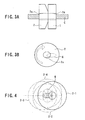
- Fig. 3 is an enlarged sectional view and a front view of cutting blades in the cutting device and
- Fig. 4 is a diagram showing trajectories of the center axes of the cutting blades.
- the cutting device includes a fixed blade 1 having a through hole at the center of a disk and a shearing blade formed on a circumferential surface 1a of the through hole, a rotating blade 2 having a through hole at the center of a disk and a shearing blade formed on a circumferential surface 2a of the through hole, a plate-shaped fixed blade holding member 3 rotatably holding the fixed blade 1 around the center axis of the through hole, and a plate-shaped rotating blade holding member 4 rotatably holding the rotating blade 2 around the center axis of the through hole.
- the rotating blade 1 and the fixed blade 2 are attached to holding members 3 and 4 so that they can be freely rotated around the center axes of the respective through holes (free rotating direction). Also, the outer diameters and the inner diameters (diameter of the through hole) of the fixed blade 1 and the rotating blade 2 are in the same size, and the center axes of the through holes are also aligned in the state where a linear member C is passed through.
- the fixed blade holding member 3 and the rotating blade holding member 4 are brought into contact with each other on their surfaces and fixed to members, not shown, so that the through holes of the fixed blade 1 and the rotating blade 2 held by respective holding members are opposed to each other.
- a through hole 4b having a vertically long opening is formed at the rotating blade holding member 4, and a fulcrum shaft 4a provided on the surface of the fixed blade holding member 3 is arranged inside thereof.
- a rotating bearing 4c is installed above the through hole 4b, and an eccentric shaft 5b directly connected to a motor shaft 5a of a motor 5 is rotatably placed inside thereof .
- the fixed blade 1 is formed to be flat on both surfaces, while the rotating blade 2 is formed with one surface flat and the other surface in a truncated cone shape.
- the truncated cone shaped surface of the rotating blade 2 is opposed to and brought into contact with the flat surface of the fixed blade 1.
- the truncated cone shaped surface permits pressure to concentrate onto the blade surface of the sharing blade.
- the eccentric shaft 5b directly connected to the motor shaft 5a of the motor 5 has its rotating center eccentric from a center P of the motor shaft 5a, and as shown by an arrow in white in Fig. 2, the eccentric shaft 5b is rotated clockwise in contact with the inner surface of the rotating bearing 4c of the eccentric shaft 5b. Therefore, by being pressed by the eccentric shaft 5b via the rotating bearing 4c, the rotating blade holding member 4 performs a vertical reciprocating motion and a horizontal oscillating motion with the fulcrum shaft 4a as a fulcrum. As a result, when the eccentric shaft 5b makes one revolution, the center of the rotating blade 2, that is, a centroid 6 of the through hole of the rotating blade 2 becomes an oval having the long axis in the horizontal direction as shown in Fig. 3B.
- the rotating blade holding member 4 performs a vertical reciprocating motion and a horizontal oscillating motion with the fulcrum shaft 4a as a fulcrum. Therefore, when the eccentric shaft 5b makes one revolution, the rotating blade 2 performs a rotating motion constituting a cycle of 2-1, 2-2, 2-3, and 2-4 in Fig. 4, and the centroid 6 becomes an oval. Since the fixed blade 1 is fixed at the position of the circle 2-1 all the time, the linear member C is cut by the fixed blade 1 and the rotating blade 2. By repeating the rotation and stop of the motor shaft 5a, the linear member C can be repeatedly cut at a high speed.
- the portion used for cutting does not concentrate at one spot as in the case where the cutting is carried out by reciprocating the center axis of the rotating blade 2 straight. Also, since the rotating blade 2 and the fixed blade 1 are rotatably mounted to the fixed blade holding member 3 and the rotating blade holding member 4 respectively, and rotate as appropriate around the center axis as shown by a broken-line arrow in Fig. 3B when cutting the linear member C, the spot to be used for cutting is changed all the time, and the portion used for cutting is further distributed.
- the rotating blade holding member 4 is driven by the eccentric shaft 5b directly connected to the motor shaft 5a, but it may be driven by a pneumatic actuator.
- the centroid of the rotating blade 2 may be a shape other than an oval as long as a closed loop is formed.
- the opposing surfaces of both the fixed blade 1 and the rotating blade 2 may be flat surfaces or truncated conical surfaces.
- the size of the outer diameters of the fixed blade 1 and the rotating blade 2 may be different with each other and the inner diameters of the fixed blade 1 and the rotating blade 2 may be different as well.
- the positions of the center axes of both the two blades may be individually capable of displacement.
- the fixed blade holding member 3 and the rotating blade holding member 4 are in contact in Fig. 1, but the fixed blade holding member 3 and the rotating blade holding member 4 do not have to be in contact as long as the fixed blade 1 and the rotating blade 2 are opposed to each other in contact.
Landscapes
- Engineering & Computer Science (AREA)
- Mechanical Engineering (AREA)
- Life Sciences & Earth Sciences (AREA)
- Forests & Forestry (AREA)
- Finish Polishing, Edge Sharpening, And Grinding By Specific Grinding Devices (AREA)
- Shearing Machines (AREA)
- Nonmetal Cutting Devices (AREA)
Abstract

Description
- The present invention relates to a device and a method for cutting a linear member and particularly to a cutting device and a cutting method of a linear member which realize a longer life and maintenance-free property of a cutting blade.
- As a process for producing a belt, which is a constituent member of a pneumatic tire, a process of helically winding a steel cord coated by rubber around a cylindrical shaft body while partially overlapping and cutting the rubber-coated cord when winding for the length of a single tire is completed is known (See Patent Document 1). Also, as a process of producing a cap-ply, which is a constituent member of a pneumatic tire, a process is known that a cap-ply ribbon made of a rubber-coated cord helically wound on a belt and the cap-ply ribbon is cut when winding for the length of a single tire is completed (See
Patent Documents 2, 3). In these processes, a scissors-type cutter or a guillotine-type cutter is used as a cutting device for cutting a rubber-coated cord. - Patent Document 1:
Japanese Patent Application Laid-Open No. 2001-252992 - Patent Document 2:
Japanese Patent Application Laid-Open No. 5-69498 - Patent Document 3:
Japanese Patent Application Laid-Open No. 7-164559 - In the case of the scissors-type cutter or the guillotine-type cutter, however, since cutting is performed at the same portion of a blade, there is a problem that the blade is deteriorated quickly and the life of the cutter is short. Therefore, running rate of equipment is lowered by time required for replacement and maintenance works for the cutter, which has become a disincentive in productivity improvement.
- The present invention was made in view of the above problem and has an object to realize a longer life and maintenance-free property of a cutter for cutting a linear member.
- An invention according to
claim 1 is a cutting device, comprising a pair of cutting blades on which a shearing blade is formed on the circumferential surface of a through hole respectively, a pair of holding means for holding the pair of cutting blades respectively, and a displacement means capable of displacement of the holding means so that the holding means are displaced relatively in a loop from a state where the center axes of the through holes of the pair of cutting blades are opposed to each other. - An invention according to
claim 2 is the cutting device described inclaim 1, wherein one of the pair of cutting blades is a fixed blade in which the center axis position of the through hole is fixed, while the other is a movable blade in which the center axis position of the through hole is capable of displacement. - An invention according to
claim 3 is the cutting device described inclaim 2, wherein the displacement means is provided with means for having the holding means of the movable blade move with respect to a predetermined fulcrum so that the center axis of the through hole of the movable blade is displaced in the loop state. - An invention according to
claim 4 is the cutting device described inclaim 1, wherein the opposed surfaces of the pair of cutting blades are a flat surface and a truncated conical surface, both are flat surfaces or both are truncated conical surfaces. - An invention according to
claim 5 is the cutting device described inclaim 1, wherein the pair of cutting blades have through holes at the center of a disk and are held rotatably around the center axis of the through hole. - An invention according to
claim 6 is a cutting method comprising the processes of: holding the two cutting blades so that the center axes of the through holes of the pair of cutting blades on which a shearing blade is formed on the circumferential surface of the through hole respectively, are opposed to each other; inserting a member to be cut through the through holes of the pair of cutting blades; and relatively displacing the center axes of the through holes of the pair of cutting blades in a loop from their aligned position. - According to the invention in
claims - According to the invention in
claims - According to the invention in
claim 5, since the cutting blade rotates, the portion used for cutting in the shearing blade formed at the circumferential surface of the through hole of the cutting blade varies. - According to the present invention, since the portion used for cutting of the shearing blade is varied and not concentrated at one location, a longer life and maintenance-free property of the cutting device can be realized.
-
- Fig. 1 is a sectional view of a cutting device according to an embodiment of the present invention;
- Fig. 2 is a front view of the cutting device according to the embodiment of the present invention;
- Fig. 3 is an enlarged sectional view and a front view of cutting blades in the embodiment of the present invention; and
- Fig. 4 is a diagram showing trajectories of the center axes of the cutting blades in the embodiment of the present invention.
-
- 1:
- Fixed blade
- 1a, 2a:
- Shearing blade
- 2:
- Rotating blade
- 3:
- Fixed blade holding member
- 4:
- Rotating blade holding member
- 4a:
- Fulcrum shaft
- 4c:
- Rotating bearing
- 5:
- Motor
- 5a:
- Motor shaft
- 5b:
- Eccentric shaft
- An embodiment of the present invention will be described below in detail referring to the attached drawings.
- Figs. 1 and 2 are a sectional view and a front view of a cutting device according to the embodiment of the present invention, respectively. Fig. 3 is an enlarged sectional view and a front view of cutting blades in the cutting device and Fig. 4 is a diagram showing trajectories of the center axes of the cutting blades.
- As shown in Figs. 1 and 2, the cutting device according to the present embodiment includes a
fixed blade 1 having a through hole at the center of a disk and a shearing blade formed on a circumferential surface 1a of the through hole, arotating blade 2 having a through hole at the center of a disk and a shearing blade formed on acircumferential surface 2a of the through hole, a plate-shaped fixedblade holding member 3 rotatably holding thefixed blade 1 around the center axis of the through hole, and a plate-shaped rotatingblade holding member 4 rotatably holding the rotatingblade 2 around the center axis of the through hole. The rotatingblade 1 and thefixed blade 2 are attached to holdingmembers fixed blade 1 and the rotatingblade 2 are in the same size, and the center axes of the through holes are also aligned in the state where a linear member C is passed through. - The fixed
blade holding member 3 and the rotatingblade holding member 4 are brought into contact with each other on their surfaces and fixed to members, not shown, so that the through holes of thefixed blade 1 and the rotatingblade 2 held by respective holding members are opposed to each other. A throughhole 4b having a vertically long opening is formed at the rotatingblade holding member 4, and afulcrum shaft 4a provided on the surface of the fixedblade holding member 3 is arranged inside thereof. Moreover, a rotating bearing 4c is installed above thethrough hole 4b, and aneccentric shaft 5b directly connected to amotor shaft 5a of amotor 5 is rotatably placed inside thereof . - As shown in Fig. 3A, the
fixed blade 1 is formed to be flat on both surfaces, while the rotatingblade 2 is formed with one surface flat and the other surface in a truncated cone shape. The truncated cone shaped surface of the rotatingblade 2 is opposed to and brought into contact with the flat surface of thefixed blade 1. The truncated cone shaped surface permits pressure to concentrate onto the blade surface of the sharing blade. - The
eccentric shaft 5b directly connected to themotor shaft 5a of themotor 5 has its rotating center eccentric from a center P of themotor shaft 5a, and as shown by an arrow in white in Fig. 2, theeccentric shaft 5b is rotated clockwise in contact with the inner surface of the rotating bearing 4c of theeccentric shaft 5b. Therefore, by being pressed by theeccentric shaft 5b via the rotatingbearing 4c, the rotatingblade holding member 4 performs a vertical reciprocating motion and a horizontal oscillating motion with thefulcrum shaft 4a as a fulcrum. As a result, when theeccentric shaft 5b makes one revolution, the center of therotating blade 2, that is, acentroid 6 of the through hole of therotating blade 2 becomes an oval having the long axis in the horizontal direction as shown in Fig. 3B. - A method of cutting a linear member by the cutting device having the above configuration will be described. First, as shown in Figs. 1, 3A and 4, while the
rotating blade 2 is aligned with the position of a circle 2-1 in Fig. 4 with respect to the fixedblade 1 fixed to the position of the circle 2-1 in Fig. 4 all the time, a linear member C to be cut is inserted through the through holes at the center of the fixedblade 1 and therotating blade 2 of the cutting device. When themotor shaft 5a is rotated from this state, the outer peripheral surface of theeccentric shaft 5b makes a rotational motion in contact with the inner surface of the rotatingbearing 4c. At this time, by being pressed by theeccentric shaft 5b via the rotatingbearing 4c, the rotatingblade holding member 4 performs a vertical reciprocating motion and a horizontal oscillating motion with thefulcrum shaft 4a as a fulcrum. Therefore, when theeccentric shaft 5b makes one revolution, therotating blade 2 performs a rotating motion constituting a cycle of 2-1, 2-2, 2-3, and 2-4 in Fig. 4, and thecentroid 6 becomes an oval. Since the fixedblade 1 is fixed at the position of the circle 2-1 all the time, the linear member C is cut by the fixedblade 1 and therotating blade 2. By repeating the rotation and stop of themotor shaft 5a, the linear member C can be repeatedly cut at a high speed. - Since the cutting device according to the embodiment is configured so that the center axis of the
rotating blade 2 draws an oval loop with respect to the center axis of the fixedblade 1 as above, the portion used for cutting does not concentrate at one spot as in the case where the cutting is carried out by reciprocating the center axis of therotating blade 2 straight. Also, since therotating blade 2 and the fixedblade 1 are rotatably mounted to the fixedblade holding member 3 and the rotatingblade holding member 4 respectively, and rotate as appropriate around the center axis as shown by a broken-line arrow in Fig. 3B when cutting the linear member C, the spot to be used for cutting is changed all the time, and the portion used for cutting is further distributed. - In the above embodiment, the rotating
blade holding member 4 is driven by theeccentric shaft 5b directly connected to themotor shaft 5a, but it may be driven by a pneumatic actuator. Moreover, the centroid of therotating blade 2 may be a shape other than an oval as long as a closed loop is formed. Also, the opposing surfaces of both the fixedblade 1 and therotating blade 2 may be flat surfaces or truncated conical surfaces. Moreover, the size of the outer diameters of the fixedblade 1 and therotating blade 2 may be different with each other and the inner diameters of the fixedblade 1 and therotating blade 2 may be different as well. Also, the positions of the center axes of both the two blades may be individually capable of displacement. Moreover, the fixedblade holding member 3 and the rotatingblade holding member 4 are in contact in Fig. 1, but the fixedblade holding member 3 and the rotatingblade holding member 4 do not have to be in contact as long as the fixedblade 1 and therotating blade 2 are opposed to each other in contact.
Claims (6)
- A cutting device, comprising:a pair of cutting blades on which a shearing blade is formed on the circumferential surface of a through hole, respectively;a pair of holding means for holding the pair of cutting blades, respectively; anda displacement means capable of displacement of the holding means so that the holding means are displaced relatively in a loop from a state where the center axes of the through holes of the pair of cutting blades are opposed to each other.
- The cutting device according to claim 1, wherein one of the pair of cutting blades is a fixed blade in which the center axis position of the through hole is fixed, while the other is a movable blade in which the center axis position of the through hole is capable of displacement.
- The cutting device according to claim 2, wherein the displacement means is provided with means for making the holding means of the movable blade move with respect to a predetermined fulcrum so that the center axis of the through hole of the movable blade is displaced in a loop.
- The cutting device according to claim 1, wherein the opposed surfaces of the pair of cutting blades are a flat surface and a truncated conical surface, both are flat surfaces or both are truncated conical surfaces.
- The cutting device according to claim 1, wherein each of the pair of cutting blades has a through hole at the center of a disk and is held rotatably around the center axis of the through hole.
- A cutting method comprising the processes of: holding two cutting blades so that the center axes of through holes of the pair of cutting blades on which a shearing blade is formed on the circumferential surface of the through hole respectively are opposed to each other; inserting a member to be cut through the through holes of the pair of cutting blades; and relatively displacing the center axes of the through holes of the pair of cutting blades in a loop from their aligned position.
Applications Claiming Priority (2)
| Application Number | Priority Date | Filing Date | Title |
|---|---|---|---|
| JP2004341622A JP4761290B2 (en) | 2004-11-26 | 2004-11-26 | Cutting device |
| PCT/JP2005/021665 WO2006057330A1 (en) | 2004-11-26 | 2005-11-25 | Cutting device and cutting method |
Publications (2)
| Publication Number | Publication Date |
|---|---|
| EP1815928A1 true EP1815928A1 (en) | 2007-08-08 |
| EP1815928A4 EP1815928A4 (en) | 2012-07-25 |
Family
ID=36498064
Family Applications (1)
| Application Number | Title | Priority Date | Filing Date |
|---|---|---|---|
| EP05809653A Withdrawn EP1815928A4 (en) | 2004-11-26 | 2005-11-25 | Cutting device and cutting method |
Country Status (4)
| Country | Link |
|---|---|
| US (1) | US20090083983A1 (en) |
| EP (1) | EP1815928A4 (en) |
| JP (1) | JP4761290B2 (en) |
| WO (1) | WO2006057330A1 (en) |
Families Citing this family (4)
| Publication number | Priority date | Publication date | Assignee | Title |
|---|---|---|---|---|
| JP2009291901A (en) * | 2008-06-06 | 2009-12-17 | Toyota Motor Corp | Cutting device |
| CN101888008A (en) * | 2009-05-13 | 2010-11-17 | 奥雷通光通讯设备(上海)有限公司 | Shearing device for radio-frequency joint inner core of duplexer or filter |
| MX371326B (en) | 2013-10-04 | 2020-01-27 | Kentmaster Mfg Co Inc | Dehiding tool. |
| DE102016117956B4 (en) | 2016-09-23 | 2019-05-09 | Rattunde & Co Gmbh | Cutting eccentric drive with variable stroke |
Family Cites Families (15)
| Publication number | Priority date | Publication date | Assignee | Title |
|---|---|---|---|---|
| US2038254A (en) * | 1932-11-10 | 1936-04-21 | Worthington Warren | Shearing method and apparatus |
| SE355739B (en) * | 1967-05-04 | 1973-05-07 | Dainippon Ink & Chemicals | |
| US3657951A (en) * | 1969-08-15 | 1972-04-25 | Harry S Clark | Tubular products cut-off and method |
| US4003279A (en) * | 1974-04-09 | 1977-01-18 | T. I. (Group Services) Limited | Shearing tube stock |
| JPS5627714A (en) * | 1979-08-08 | 1981-03-18 | Showa Electric Wire & Cable Co Ltd | Wire cutter |
| EP0255551B1 (en) * | 1986-08-06 | 1990-12-27 | Shearing Industries International, Inc. | Tubular and bar stock cutting apparatus |
| US4635514A (en) * | 1985-05-03 | 1987-01-13 | Alexander Borzym | Elliptical shearing apparatus |
| JPS6352916A (en) * | 1986-08-13 | 1988-03-07 | シアリング インダストリーズ インターナショナル インコーポレーテッド | Elliptic shearing device |
| US4794834A (en) * | 1987-05-15 | 1989-01-03 | Eaton Corporation | Tube shearing apparatus |
| JPS6420916A (en) * | 1987-07-13 | 1989-01-24 | Shogo Tsukada | X and y two-dimensional cutting device |
| DE59003596D1 (en) * | 1989-09-27 | 1994-01-05 | Hatebur Umformmaschinen Ag Rei | Method and device for pulling wire into a shearing station of a forming press. |
| JPH07100251B2 (en) * | 1990-11-20 | 1995-11-01 | アイダエンジニアリング株式会社 | Round bar cutting method and cutting device |
| JPH06344216A (en) * | 1993-06-02 | 1994-12-20 | Ootsuki Seiki:Kk | How to cut wire |
| US6352012B1 (en) * | 1997-09-30 | 2002-03-05 | John J. Borzym | Supported shear with reversible linear drive and in-feed table therefor |
| JP4315669B2 (en) * | 2001-12-04 | 2009-08-19 | 株式会社神戸製鋼所 | Method and apparatus for cutting metal bar |
-
2004
- 2004-11-26 JP JP2004341622A patent/JP4761290B2/en not_active Expired - Fee Related
-
2005
- 2005-11-25 EP EP05809653A patent/EP1815928A4/en not_active Withdrawn
- 2005-11-25 WO PCT/JP2005/021665 patent/WO2006057330A1/en not_active Ceased
- 2005-11-25 US US11/719,961 patent/US20090083983A1/en not_active Abandoned
Also Published As
| Publication number | Publication date |
|---|---|
| EP1815928A4 (en) | 2012-07-25 |
| US20090083983A1 (en) | 2009-04-02 |
| WO2006057330A1 (en) | 2006-06-01 |
| JP2006150478A (en) | 2006-06-15 |
| JP4761290B2 (en) | 2011-08-31 |
Similar Documents
| Publication | Publication Date | Title |
|---|---|---|
| CN113394466B (en) | Diaphragm non-deceleration film cutting and winding mechanism | |
| EP1970175A1 (en) | Clamping device for transversal cutting machines of logs of paper | |
| JP2019149935A5 (en) | ||
| JP2019149935A (en) | Device for removing anti-snow accretion ring | |
| US20090083983A1 (en) | Cutting Device And Cutting Method | |
| JP4989159B2 (en) | Method and apparatus for splitting string-like material | |
| US8905827B1 (en) | Dehider tool and blade therefor | |
| EP3231566B1 (en) | Cutting device and method for operating same | |
| JP2009039782A (en) | Scrap discharging device in spinning process | |
| CN114728427B (en) | Cutting machine for transversely cutting a roll of sheet material | |
| EP1454832B1 (en) | Rotating device for cutting tubular labels from a tubular label web | |
| US20180071935A1 (en) | Device for cutting a sheet or layer of material | |
| JP2014083635A (en) | Pipe cutter | |
| CN221133874U (en) | Wire cutting device of motor stator | |
| US5655427A (en) | Stapling device with rotary cutting element | |
| US5463919A (en) | Apparatus for cutting wound coils | |
| JPH11510442A (en) | Cutting wheel mechanism with selectively rotatable cutting blade | |
| CN114829050B (en) | Plate cutting device | |
| CN109514629A (en) | A kind of cutoff device and blank method | |
| JP2013544686A (en) | Device for embedding fine wires in a deformed rubber element with a rotating needle with no sharp tip | |
| JP3839824B2 (en) | Wire electrode cutting device | |
| CN221396567U (en) | Copper-nickel wire winding device | |
| KR200486613Y1 (en) | Cutting module for use of game machine | |
| CN116213809B (en) | Automatic trimming's of integral type plate shearing machine | |
| JP4618022B2 (en) | Cutting device |
Legal Events
| Date | Code | Title | Description |
|---|---|---|---|
| PUAI | Public reference made under article 153(3) epc to a published international application that has entered the european phase |
Free format text: ORIGINAL CODE: 0009012 |
|
| 17P | Request for examination filed |
Effective date: 20070525 |
|
| AK | Designated contracting states |
Kind code of ref document: A1 Designated state(s): DE ES FR IT |
|
| DAX | Request for extension of the european patent (deleted) | ||
| RBV | Designated contracting states (corrected) |
Designated state(s): DE ES FR IT |
|
| A4 | Supplementary search report drawn up and despatched |
Effective date: 20120625 |
|
| RIC1 | Information provided on ipc code assigned before grant |
Ipc: B26D 5/14 20060101ALI20120619BHEP Ipc: B26D 1/45 20060101ALI20120619BHEP Ipc: B23D 23/00 20060101AFI20120619BHEP |
|
| STAA | Information on the status of an ep patent application or granted ep patent |
Free format text: STATUS: THE APPLICATION IS DEEMED TO BE WITHDRAWN |
|
| 18D | Application deemed to be withdrawn |
Effective date: 20130123 |