EP1815229B1 - Evaluating method of the fracture toughness using the continuous indentation method - Google Patents
Evaluating method of the fracture toughness using the continuous indentation method Download PDFInfo
- Publication number
- EP1815229B1 EP1815229B1 EP05808740.4A EP05808740A EP1815229B1 EP 1815229 B1 EP1815229 B1 EP 1815229B1 EP 05808740 A EP05808740 A EP 05808740A EP 1815229 B1 EP1815229 B1 EP 1815229B1
- Authority
- EP
- European Patent Office
- Prior art keywords
- indentation
- elastic modulus
- fracture
- calculating
- fracture toughness
- Prior art date
- Legal status (The legal status is an assumption and is not a legal conclusion. Google has not performed a legal analysis and makes no representation as to the accuracy of the status listed.)
- Expired - Lifetime
Links
Images



Classifications
-
- G—PHYSICS
- G01—MEASURING; TESTING
- G01N—INVESTIGATING OR ANALYSING MATERIALS BY DETERMINING THEIR CHEMICAL OR PHYSICAL PROPERTIES
- G01N3/00—Investigating strength properties of solid materials by application of mechanical stress
- G01N3/40—Investigating hardness or rebound hardness
- G01N3/42—Investigating hardness or rebound hardness by performing impressions under a steady load by indentors, e.g. sphere, pyramid
-
- G—PHYSICS
- G01—MEASURING; TESTING
- G01N—INVESTIGATING OR ANALYSING MATERIALS BY DETERMINING THEIR CHEMICAL OR PHYSICAL PROPERTIES
- G01N2203/00—Investigating strength properties of solid materials by application of mechanical stress
- G01N2203/0058—Kind of property studied
- G01N2203/006—Crack, flaws, fracture or rupture
- G01N2203/0062—Crack or flaws
- G01N2203/0064—Initiation of crack
-
- G—PHYSICS
- G01—MEASURING; TESTING
- G01N—INVESTIGATING OR ANALYSING MATERIALS BY DETERMINING THEIR CHEMICAL OR PHYSICAL PROPERTIES
- G01N2203/00—Investigating strength properties of solid materials by application of mechanical stress
- G01N2203/0058—Kind of property studied
- G01N2203/0069—Fatigue, creep, strain-stress relations or elastic constants
- G01N2203/0075—Strain-stress relations or elastic constants
-
- G—PHYSICS
- G01—MEASURING; TESTING
- G01N—INVESTIGATING OR ANALYSING MATERIALS BY DETERMINING THEIR CHEMICAL OR PHYSICAL PROPERTIES
- G01N2203/00—Investigating strength properties of solid materials by application of mechanical stress
- G01N2203/0058—Kind of property studied
- G01N2203/0076—Hardness, compressibility or resistance to crushing
- G01N2203/0078—Hardness, compressibility or resistance to crushing using indentation
Definitions
- the present invention relates, in general, to methods for evaluating fracture toughness of materials using a continuous indentation technique and, more particularly, to a method for evaluating the fracture toughness of a material using the continuous indentation technique, wherein the elastic modulus of the material corresponding to an indentation depth is primarily determined using the continuous indentation technique and, thereafter, the characteristic fracture initiation point of the indentation depth is determined, so that the fracture toughness of a brittle material can be determined precisely using a nondestructive evaluation technique based on the relationship between energy, continuously absorbed by the material until the indentation depth has reached the characteristic fracture initiation point, and the fracture energy of the material.
- Fracture Toughness (K JC ), which represents the crack growth resistance of a material, is an important property of the material when evaluating the structural soun dness of the material.
- conventional fracture toughness evaluation methods must require test-pieces having specified shapes and sizes in order to be reliable. In other words, a crack is preformed in a test-piece and, thereafter, stress and strain around the crack are mechanically analyzed, so that an appropriate test capable of determining the crack size and the crack growth direction can be conducted. Thereafter, fracture conditions can be determined using the test. Examples of representative fracture toughness tests are a compact tension test and a three-point-single edge notched bend test, each of which uses fatigue precracking.
- a plurality of test-pieces having specified crack growth directions and crack sizes must be produced from a material.
- the crack growth of the material can be determined while fracturing the test-pieces.
- the complex test procedure which includes the fatigue precracking and the crack length evaluation, makes it difficult to evaluate the fracture toughness.
- the conventional fracture toughness evaluation method uses a destructive technique in which a test-piece is cut from a material. Thus, the conventional method cannot be adapted to actively operated industrial structures.
- Methods and apparatus for determining properties of a test material by scratch testing ( WO 2003/087778 )
- Method for measurement of the fracture toughness of a coating or a surface WO 2002/18905
- Methodhod and apparatus for determining fracture toughness ( WO 2004/015398 )
- Method and apparatus for determining properties of a test material by scratch testing involves an apparatus and method for calculating characteristics of materials, such as equivalent strain, using an indenter where the method used is independent of indenter geometry.
- Method for measurement of the fracture toughness of a coating or a surface relates to a method in which a hard stylus is drawn with an increasing normal force along the surface of an object so that the surface undergoes damage by fracture.
- Method and apparatus for determining fracture toughness is in order to determine fracture toughness of e.g. a sheet of paper, the sheet is cut to provide a double-edge notched tension geometry, with the notches defining a ligament therebetween of length.
- the conventional theories and models to evaluate the fracture toughness of materials using the indentation techniques are limited to use in evaluating the fracture toughness of brittle materials.
- the conventional evaluation models using the indentation techniques are only effective when a subject brittle material is in a temperature range lower than the ductile-brittle transition temperature (DBTT) of the brittle material. If the brittle material is in a temperature range which is not lower than the ductile-brittle transition temperature (DBTT) of the brittle material, an indentation cannot form a crack in the brittle material, so that the fracture toughness evaluation of brittle materials using indentation techniques must be studied and developed.
- DBTT ductile-brittle transition temperature
- an object of the present invention is to provide a method for evaluating the fracture toughness of a material using the continuous Indentation technique, which executes a nondestructive evaluation of the fracture toughness of a brittle material using the continuous indentation technique.
- Another object of the present invention is to provide a method for evaluating the fracture toughness of a material using the continuous indentation technique, which can evaluate the fracture toughness of the material using only the continuous indentation test data without requiring a test-piece to be cut from the material.
- a further object of the present invention is to provide a method for evaluating the fracture toughness of a material using the continuous indentation technique, which can evaluate the fracture toughness of the material without limiting the size and shape of a test-piece or the material, and which easily and efficiently evaluates fracture toughness unlike a conventional evaluation method.
- the present invention uses the idea of continuous damage mechanics (CDM) and critical void volume fraction (f) to determine the characteristic fracture initiation point (h*) of the indentation depth during or after the indentation process.
- CDM continuous damage mechanics
- f critical void volume fraction
- the fracture toughness which is evaluated using the continuous indentation test data according to the model of the present invention, is compared to the fracture toughness value determined by the standard fracture toughness evaluation technique.
- the present invention is advantageous in that it can precisely evaluate the fracture toughness of a brittle material using a nondestructive evaluation technique.
- the present invention can evaluate the properties and fracture toughness of a material using a nondestructive evaluation technique and an indentation tester placed on the material at a predetermined position without cutting the material, so that the present invention does not limit the size and shape of the material.
- the present invention can be used to evaluate the fracture toughness of a material precisely using an indentation tester placed around a pipeline or an industrial structure before, during or after the practical operation thereof.
- the present invention can evaluate the fracture toughness of a material using a simple continuous indentation technique, thus increasing productivity and work efficiency while evaluating the fracture toughness.
- an embodiment of the present invention provides a method of evaluating the fracture toughness of a material using a continuous indentation technique of continuously measuring an indentation load and an indentation depth while repeatedly applying and removing the load to and from the material, the method including the steps of: measuring a stress coefficient, a strain hardening modulus and a yield stress using the continuous indentation technique and calculating a reduced elastic modulus (E r ); calculating an effective elastic modulus (E eff ) from the reduced elastic modulus; determining an initial elastic modulus (E 0 ) from the elastic modulus in a first range of the effective elastic modulus, which was determined using a plurality of unloading curves obtained using the continuous indentation technique; setting a void volume fraction (f) to a specific value within a range from 0.13 to 0.17 when the fracture type of the material is a I-type fracture type, and setting the void volume fraction (f) to a specific value within a range from 0.23 to 0.27 when
- FIG. 1 is a sectional view showing the construction of a continuous indentation tester used in the present invention.
- the present invention uses an indentation tester 100 which is disclosed in Korean Patent Application No. 2001-16070 entitled "Indentation tester, method of providing indentation test data and evaluating the properties of a material using the indentation tester, and recording medium having the property evaluation method thereon".
- the indentation tester 100 comprises a loading unit 110 to generate an indentation load using the rotation of a motor 111, a load sensor 123, and indenter holder 125, and an indenter 127.
- the rotational force generated from the motor 111 rotates a ball screw 117 and rectilinearly moves an external ball screw nut 118 upwards and downwards in vertical directions.
- vertical pressure is transmitted to a test-piece through the indenter 127, thus generating compressive stress.
- the load sensor 123 continuously measures the variation in the indentation load applied to the test-piece.
- a strain sensor provided in the continuous indentation tester 100 continuously measures the indentation depth of the indenter 127.
- the indentation load and the indentation depth are measured to a predetermined depth using the load sensor 123 and the strain sensor and, thereafter, the indentation load and the indentation depth are measured again while rotating the motor 111 in a reverse direction and removing some of the indentation load from the indenter 127, thus continuously executing the process of determining the stress and modulus of strain at the same place.
- an indentation load is applied again to the indenter 127 through the above-mentioned method, thus further indenting the material surface and increasing the indentation depth and measuring the indentation load and indentation depth and, thereafter, the indentation load and the indentation depth are measured again while removing some of the indentation load from the indenter 127, thus continuously determining the stress and modulus of strain.
- stress and strain modulus curves can be obtained at the same place.
- the present invention uses a technique of evaluating the properties of a material using the continuous indentation tester 100 which can measure the properties of the material while repeatedly applying and removing indentation load to and from the material.
- the evaluation technique used in the present invention remains the same as that described in the related art and further explanation is thus not deemed necessary.
- Equation 1 The fracture toughness (K JC ) on an infinite plane having a length 2a is calculated using Equation 1.
- K J C ⁇ f ⁇ ⁇ a wherein ⁇ f represents a remote tensile stress at the fracture.
- the remote tensile stress ( ⁇ f ) at the fracture is represented using Equation 2 according to Griffith's theory.
- ⁇ f 2 ⁇ E ⁇ f ⁇ a wherein E represents the elastic modulus, and ⁇ f represents energy absorbed by the material until the material is fractured.
- Equation 1 and Equation 2 are combined together, the relationship between energy ( ⁇ f ) and fracture toughness (K JC ) is represented using Equation 3.
- K J C 2 ⁇ E ⁇ ⁇ f
- the energy ( ⁇ f ) must be represented by indentation parameters.
- the stress triaxiality of the lower part of the indenter ranges between 2 and 3, and this restriction of the strain range of the lower part of the indenter is similar to that of the front part of a crack tip.
- h* characteristic fracture initiation point
- FIG. 2 is a graph showing an indentation load-indentation depth curve.
- the critical indentation energy (2 ⁇ f ) can be calculated using the indentation load-indentation depth curve.
- 2 ⁇ ⁇ f lim h ⁇ h * ⁇ 0 h F A c d h
- F represents an indentation load
- h represents an indentation depth
- a C represents a contact surface area
- h * represents a characteristic fracture initiation point (the indentation depth corresponding to critical elastic modulus).
- 2 ⁇ f represents fracture energy
- the Arabic numeral 2 in front of ⁇ f is determined by the fact that two surfaces are formed in the upper and lower regions while a crack grows.
- 2 ⁇ f is primarily calculated using the data measured by the continuous indentation technique and the calculation results are, thereafter, used in Equation 3 along with the elastic modulus of the material, so that the fracture toughness of the material can be determined.
- the characteristic fracture initiation point (h * ) of the indentation depth must be determined.
- the elastic modulus during the indentation process must be calculated as follows.
- the effective elastic modulus can be analyzed from the reduced elastic modulus calculated using Equation 5.
- the effective elastic modulus is reduced.
- Furthemore, the effective elastic modulus is represented by a mathematical function comprising the indentation parameters.
- the effective elastic modulus can be analyzed from the reduced elastic modulus.
- E eff 1 - v 2 1 E r - 1 - v i 2 E i + 1 - v 2 2 ⁇ A C ⁇ ⁇ S - 1 - v i 2 E i
- ⁇ and ⁇ i represent Poisson's ratios of the material and the indenter, respectively
- E represents reduced elastic modulus
- E i represents the elastic modulus of the indenter
- A represents a contact surface area between the indenter and the material
- S represents the slope of the unloading curve.
- Example 1 if the type of material is known
- FIG. 3 is a view schematically showing the progress of a brittle fracture according to an increase in the void volume fracture (f) during a typical brittle fracture.
- the indentation load when the indentation load is applied to the material, voids are formed in the material. Furthermore, the indentation load applied to the material increases, so that deformation occurs in the material, resulting in void growth and causing the voids to coalesce with neighboring voids and enlarging the void sizes.
- the mechanism relating to void generation, void growth and void coalescence during the brittle fracture is adapted to the present invention while considering the stress conditions in the indentation test.
- FIG. 4 is a view schematically showing the formation of the voids in the material according to the indentation.
- the material when an indentation load is applied to the material, the material is deformed to create an indentation depth (h).
- the indentation depth increases, the deformation of the material at a position under the indenter increases, thus forming voids in the material.
- the indentation load is compressive along a loading axis, the deformation region under the indenter is subjected to a compressive force.
- voids are formed in the material due to the partial shearing stress caused by the compressive force.
- the void volume fraction proportionally increases. This means that the material is damaged.
- the damage parameter (D) relates to the surface density of micro-defects in the material.
- D s D s wherein s and s D are the overall sectional area of a loading region and a surface area occupied by the micro-defects on the overall sectional area, respectively.
- the damage parameter (D) can be calculated from the variation in the elastic modulus using Lemaitre's strain equivalence principle.
- the critical void volume fraction principle is used.
- the experiments of Brown and Embury and the experiments of Goods and Brown show that the voids start to coalesce together when the void volume fraction (f) ranges from about 0.13 to 0.17, and the void coalescence starts when the void volume fraction (f) is not higher than 0.2.
- the numerical analysis of Anderson shows that the stable crack growth of a brittle material starts when the void volume fraction (f) ranges from about 0.23 to 0.27. Tebogard used the above-mentioned standard to the cup-corn fracture analysis.
- the two void volume fractions (f C and f F ) are used to determine the critical elastic modulus. If the fracture type of a material is known, the damage parameter (D) of the material can be calculated as follows. If the material is a Type-I material, the damage parameter (D) of the material can be determined using a specified value within a range from 0.13 to 0.17, corresponding to the properties of the material, as the void volume fraction in Equation 9.
- the damage parameter (D) can be determined using a specified value within a range from 0.23 to 0.27 as the void volume fraction in Equation 9.
- Table 1 Type Material Exact valueKJC(MP am 0.5 ) 0.13 0.15 0.17 0.23 0.25 0.27
- Type I SA508 144 117 131 145 SUJ2 111 99 108 117 SKS3 95 111 128 151 S45C 150 115 131 153
- Table 1 shows variation in the evaluated fracture toughness of a material according to variation in the void volume fraction of the material. As illustrated in Table 1, every material has a specific void volume fraction which can be used to evaluate the fracture toughness of the material most precisely (as underlined and bold in the Table). Therefore, it is preferable to evaluate the fracture toughness of the materials after setting the appropriate void volume fractions according to the properties and types of the materials.
- the Type-I materials and the Type-II materials will be described in detail in the description of the experimental results.
- D C the damage parameter of a material using the void volume fraction (f) within the range from 0.23 to 0.27
- D F the damage parameter of the material can be determined through iteration, as will be described in Example 2.
- the value E is the elastic modulus obtained from the analysis of the first unloading curve of a plurality of unloading curves determined through repeated loading and unloading.
- the value E is the initial elastic modulus of an undamaged material as described above. Damage to the material caused by voids at the initial stage of indentation is negligible, so that the state of the material at the initial stage of indentation may be considered an undamaged state.
- FIG. 5 is a graph showing the relationship between the effective elastic modulus (E eff ) and the indentation depth (h).
- the relationship between the effective elastic modulus and the indentation depth may be defined as illustrated in the graph of the drawing. If the critical elastic modulus (E * ) was determined, the indentation depth corresponding to the critical elastic modulus (E * ) can be determined from the characteristic fracture initiation point (h * ) of the indentation depth. In this case, the characteristic fracture initiation point must be placed between the points in the graph of FIG.
- Equation 11 the Y-axial component of a line obtained through an ln-ln fitting of curves of the critical elastic modulus and the characteristic fracture initiation point of the indentation depth is defined as A, and the slope of the line obtained through the fitting is defined as B.
- the characteristic fracture initiation point (h * ) of the indentation depth can be determined using Equation 11, the values A and B and the critical elastic modulus (E * ) having been obtained using Equation 10.
- Equation 12 is the equation which is created using only the data obtained from combination of Equations 3 and 4 during an indentation process.
- E 0 can be determined from the first unloading curve
- h * can be determined from the relationship between the critical void volume fraction, the damage parameter and the critical elastic modulus (E * ).
- the present invention can evaluate the fracture toughness of a material using the continuous indentation technique including the above-mentioned continuous processes.
- Example 2 if the type of material is not known
- Example 1 the method of evaluating the fracture toughness of a material, whose fracture type is known, has been described.
- the damage parameter (D 0.20 ) and the critical elastic modulus of the material may be determined using the void volume fraction set to 0.20, which is the average of the void volume fractions of the Type-I materials and the Type-II materials.
- the damage parameter (D 0.20 ) is determined by substitution of 0.20 for the void volume fraction (f) in Equation 9 and the critical elastic modulus is calculated.
- the critical elastic modulus in the above case is represented by E * im .
- E * i m E 0 ⁇ 1 - d 0.20
- Equation 11 The fracture toughness of the material is calculated by substitution of the critical elastic modulus (E * im ) in Equation created by transforming Equation 11 and Equation 12.
- E * im critical elastic modulus
- h * i m exp ln E * i m - A B K J
- C i m E 0 ⁇ ⁇ k ⁇ ln ⁇ 2 ⁇ R 2 ⁇ R - h * i m
- the plastic zone size (PZS) is calculated from the determined fracture toughness of the material.
- PZS 2.5 ⁇ K JCim / Y S 2 wherein YS represents the yield stress of the material determined using the continuous indentation technique.
- the material is determined to be Type-I material having a void volume fraction ranging from 0.13 to 0.17.
- the material is determined to be Type-II material having a void volume fraction ranging from 0.23 to 0.27.
- the fracture toughness of the material is evaluated using the method described in Example 1. Described in detail, in the method of Example 2, the plastic zone size is determined using a void volume fraction set to 0.20, which is the average of the void volume fraction of the Type-I materials and the void volume fraction of the Type-II materials. Thereafter, the void volume fraction is more precisely determined using the plastic zone size prior to determining the fracture toughness of the material.
- CTOD critical Crack Tip Opening Displacement
- Type-I materials the materials showing a ⁇ U -type fracture behavior characteristic of relatively brittle materials are classified as Type-I materials, while the materials showing a ⁇ m -type fracture behavior characteristic of relatively soft materials are classified as Type-II materials.
- the ⁇ U -type materials are the relatively brittle materials and have a smaller resistance to the force that deforms the ligament between voids in comparison to the ⁇ m -type materials, so that the load support power of the ⁇ U -type materials is quickly reduced just after the void coalescence starts.
- the stable crack growth starts and the load support power is gradually reduced, so that the ⁇ m -type materials maintain desired load support power after the void coalescence m starts.
- the value f C may be used as the critical void volume fraction of the ⁇ U -type material (type-I material), while the value f may be used as the critical void volume fraction of the ⁇ M -type material (type-II material).
- FIGS. 8 and 9 are graphs illustrating the relationship between the effective elastic modulus and the indentation depth according to the fracture type, in which FIG. 8 shows the relationship of the Type-I material, and FIG. 9 shows the relationship of the Type-II material.
- FIG. 10 is a graph showing a method of determining the characteristic fracture initiation point of the indentation depth using the effective elastic modulus -indentation depth curve.
- FIG. 11 is a graph showing a method of determining the characteristic fracture initiation point of the indentation depth using the effective elastic modulus-indentation depth curve and an extrapolation method.
- FIG. 12 is a graph comparatively illustrating the fracture toughness values evaluated using the continuous indentation technique and CTOD.
- the fracture toughness of thirteen materials, evaluated using the continuous indentation technique which is the nondestructive evaluation technique according to the present invention is almost equal to the fracture toughness evaluated using the conventional CTOD technique.
- the method of evaluating the fracture toughness of a material using the nondestructive evaluation technique according to the present invention can be used as an effective technique substituting for the conventional destructive evaluation technique.
Landscapes
- Physics & Mathematics (AREA)
- Health & Medical Sciences (AREA)
- Life Sciences & Earth Sciences (AREA)
- Chemical & Material Sciences (AREA)
- Analytical Chemistry (AREA)
- Biochemistry (AREA)
- General Health & Medical Sciences (AREA)
- General Physics & Mathematics (AREA)
- Immunology (AREA)
- Pathology (AREA)
- Investigating Strength Of Materials By Application Of Mechanical Stress (AREA)
Description
- The present invention relates, in general, to methods for evaluating fracture toughness of materials using a continuous indentation technique and, more particularly, to a method for evaluating the fracture toughness of a material using the continuous indentation technique, wherein the elastic modulus of the material corresponding to an indentation depth is primarily determined using the continuous indentation technique and, thereafter, the characteristic fracture initiation point of the indentation depth is determined, so that the fracture toughness of a brittle material can be determined precisely using a nondestructive evaluation technique based on the relationship between energy, continuously absorbed by the material until the indentation depth has reached the characteristic fracture initiation point, and the fracture energy of the material.
- Fracture Toughness (KJC), which represents the crack growth resistance of a material, is an important property of the material when evaluating the structural soun dness of the material. However, conventional fracture toughness evaluation methods must require test-pieces having specified shapes and sizes in order to be reliable. In other words, a crack is preformed in a test-piece and, thereafter, stress and strain around the crack are mechanically analyzed, so that an appropriate test capable of determining the crack size and the crack growth direction can be conducted. Thereafter, fracture conditions can be determined using the test. Examples of representative fracture toughness tests are a compact tension test and a three-point-single edge notched bend test, each of which uses fatigue precracking. To execute the above-mentioned tests, a plurality of test-pieces having specified crack growth directions and crack sizes (refer to ASTM standards about the loading direction and crack growth direction) must be produced from a material. The crack growth of the material can be determined while fracturing the test-pieces.
- However, the complex test procedure, which includes the fatigue precracking and the crack length evaluation, makes it difficult to evaluate the fracture toughness. Furthermore, the conventional fracture toughness evaluation method uses a destructive technique in which a test-piece is cut from a material. Thus, the conventional method cannot be adapted to actively operated industrial structures.
- To mitigate the above-mentioned problems experienced in the conventional fracture toughness evaluation method, a variety of fracture toughness evaluation theories and models using indentation techniques have been studied and developed.
- For example, "Method and apparatus for determining properties of a test material by scratch testing (
WO 2003/087778 )" and "Method for measurement of the fracture toughness of a coating or a surface (WO 2002/18905 WO 2004/015398 )" are the conventional evaluation theories and models. - "Method and apparatus for determining properties of a test material by scratch testing (
WO 2003/087778 )" involves an apparatus and method for calculating characteristics of materials, such as equivalent strain, using an indenter where the method used is independent of indenter geometry. - "Method for measurement of the fracture toughness of a coating or a surface (
WO 2002/18905 - "Method and apparatus for determining fracture toughness (
WO 2004/015398 )" is in order to determine fracture toughness of e.g. a sheet of paper, the sheet is cut to provide a double-edge notched tension geometry, with the notches defining a ligament therebetween of length. - However, the conventional theories and models to evaluate the fracture toughness of materials using the indentation techniques are limited to use in evaluating the fracture toughness of brittle materials. Furthermore, the conventional evaluation models using the indentation techniques are only effective when a subject brittle material is in a temperature range lower than the ductile-brittle transition temperature (DBTT) of the brittle material. If the brittle material is in a temperature range which is not lower than the ductile-brittle transition temperature (DBTT) of the brittle material, an indentation cannot form a crack in the brittle material, so that the fracture toughness evaluation of brittle materials using indentation techniques must be studied and developed.
- Accordingly, the present invention has been made keeping in mind the above problem occurring in the prior art, and an object of the present invention is to provide a method for evaluating the fracture toughness of a material using the continuous Indentation technique, which executes a nondestructive evaluation of the fracture toughness of a brittle material using the continuous indentation technique.
- Another object of the present invention is to provide a method for evaluating the fracture toughness of a material using the continuous indentation technique, which can evaluate the fracture toughness of the material using only the continuous indentation test data without requiring a test-piece to be cut from the material.
- A further object of the present invention is to provide a method for evaluating the fracture toughness of a material using the continuous indentation technique, which can evaluate the fracture toughness of the material without limiting the size and shape of a test-piece or the material, and which easily and efficiently evaluates fracture toughness unlike a conventional evaluation method.
- The present invention uses the idea of continuous damage mechanics (CDM) and critical void volume fraction (f) to determine the characteristic fracture initiation point (h*) of the indentation depth during or after the indentation process. The fracture toughness, which is evaluated using the continuous indentation test data according to the model of the present invention, is compared to the fracture toughness value determined by the standard fracture toughness evaluation technique.
- The present invention is advantageous in that it can precisely evaluate the fracture toughness of a brittle material using a nondestructive evaluation technique.
- Unlike conventional fracture toughness evaluation methods which require test-pieces having specified crack growth directions and sizes to be cut from subject materials, the present invention can evaluate the properties and fracture toughness of a material using a nondestructive evaluation technique and an indentation tester placed on the material at a predetermined position without cutting the material, so that the present invention does not limit the size and shape of the material.
- Furthermore, the present invention can be used to evaluate the fracture toughness of a material precisely using an indentation tester placed around a pipeline or an industrial structure before, during or after the practical operation thereof. In addition, the present invention can evaluate the fracture toughness of a material using a simple continuous indentation technique, thus increasing productivity and work efficiency while evaluating the fracture toughness.
-
-
FIG. 1 is a sectional view illustrating the construction of a continuous indentation tester used in the present invention; -
FIG. 2 is a graph illustrating a curve of indentation load-indentation depth of the present invention; -
FIG. 3 is a view schematically illustrating the formation of voids in a material due to indentation; -
FIG. 4 is a view schematically illustrating the progress of a ductile fracture according to an increase in the void volume fraction; -
FIG. 5 is a graph illustrating effective elastic modulus (Eeff) as a function of indentation depth (h); -
FIGS. 6 and 7 are graphs illustrating the shapes of curves of indentation load as a function of displacement during a fracture toughness test according to the fracture type; -
FIGS. 8 and9 are graphs illustrating effective elastic modulus as a function of indentation depth of a material during a fracture toughness test according to the fracture type; -
FIG. 10 is a graph illustrating a method of determining a characteristic fracture initiation point of the indentation depth using the effective elastic modulus-indentation depth curve; -
FIG. 11 is a graph illustrating a method of determining a characteristic fracture initiation point of the indentation depth using the effective elastic modulus-indentation depth curve and an extrapolation method; and -
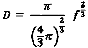
FIG. 12 is a graph comparatively illustrating the fracture toughness values evaluated using the continuous indentation technique and CTOD. - To solve the above-mentioned problems, an embodiment of the present invention provides a method of evaluating the fracture toughness of a material using a continuous indentation technique of continuously measuring an indentation load and an indentation depth while repeatedly applying and removing the load to and from the material, the method including the steps of: measuring a stress coefficient, a strain hardening modulus and a yield stress using the continuous indentation technique and calculating a reduced elastic modulus (Er); calculating an effective elastic modulus (Eeff) from the reduced elastic modulus; determining an initial elastic modulus (E0) from the elastic modulus in a first range of the effective elastic modulus, which was determined using a plurality of unloading curves obtained using the continuous indentation technique; setting a void volume fraction (f) to a specific value within a range from 0.13 to 0.17 when the fracture type of the material is a I-type fracture type, and setting the void volume fraction (f) to a specific value within a range from 0.23 to 0.27 when the fracture type of the material is a II-type fracture type; calculating a damage parameter (D) from the void volume fraction using the equation
; calculating a critical elastic modulus (E*) using the damage parameter; calculating a characteristic fracture initiation point (h*) of the indentation depth using the critical elastic modulus; and calculating the fracture toughness (KJC) of the material using the characteristic fracture initiation point and the equation
, wherein k' represents the slope (Lmax/hmax) between the maximum indentation load and max max the maximum indentation depth in the unloading curve,
2ωf is a critical indentation energy,
F is the indentation load,
AC is a contact surface area between the material and the indenter, and
R is a radius of the indenter of the continuous indentation tester. - In an effort to solve the above-mentioned problems, another embodiment of the present invention provides a method of evaluating the fracture toughness of a material using a continuous indentation technique of continuously measuring an indentation load and an indentation depth while repeatedly applying and removing the indentation load to and from the material, the method including the steps of: measuring a stress coefficient, a strain hardening modulus and a yield stress using the continuous indentation technique and calculating a reduced elastic modulus; calculating an effective elastic modulus from the reduced elastic modulus; determining an initial elastic modulus from an elastic modulus in a first range of the effective elastic modulus, which was determined using a plurality of unloading curves obtained using the continuous indentation technique; setting a void volume fraction to 0.20 when the fracture type of the material is not known; calculating a damage parameter from the void volume fraction using the equation

; calculating a critical elastic modulus (E* im) using the damage parameter; calculating a characteristic fracture initiation point (h* im) of the indentation depth using the critical elastic modulus; calculating a first fracture toughness (KJCim) of the material using the characteristic fracture initiation point of the indentation depth using the equation
; and calculating a plastic zone size (PZS) using the first fracture toughness, wherein k' represents the slope between the maximum indentation load and the maximum indentation depth in the unloading curve,
2ωf is a critical indentation energy,
F is the indentation load,
AC is a contact surface area between the material and the indenter, and
R is a radius of the indenter,
and wherein, when the plastic zone size is less than or equal to 0.4, the void volume fraction is set to a specific value within a range from 0.13 to 0.17, and when the plastic zone size is more than 0.4, the volume fraction is set to a specific value within a range from 0.23 to 0.27 and is used to calculate the fracture toughness as follows: - calculating a damage parameter (D) from the void volume fraction using the equation

- calculating a critical elastic modulus (E*) using the damage parameter;
- calculating a characteristic fracture initiation point (h*) of the indentation depth using the critical elastic modulus,
- and calculating the fracture toughness (KJC) of the material using the characteristic fracture initiation point of the indentation depth using the following equation

- The critical indentation energy (2ωf) is calculated using the equation

, wherein Ac represents a contact surface area between the material and an indenter, F represents the indentation load, h represents the indentation depth, and h* represents the characteristic fracture initiation point of the indentation depth. - The reduced elastic modulus is calculated using the equation

, wherein S represents the slope of the unloading curve. - The effective elastic modulus is calculated using the equation

, wherein ν and νi represent Poisson's ratios of the material and the indenter, respectively, and Ei represents the elastic modulus of the indenter. - The critical elastic modulus is calculated using the equation

- The characteristic fracture initiation point of the indentation depth is calculated using the equation

- The critical elastic modulus is calculated using the equation

- The characteristic fracture initiation point of the indentation depth is calculated using the equation

- The plastic zone size, PZS, is calculated using the equation

, wherein YS represents the yield stress of the material which is evaluated using the continuous indentation technique. - Herein below, the present invention will be described in detail with reference to the accompanying drawings.
-
FIG. 1 is a sectional view showing the construction of a continuous indentation tester used in the present invention. To evaluate the properties of a material, the present invention uses anindentation tester 100 which is disclosed in Korean Patent Application No.2001-16070 - The
indentation tester 100 comprises aloading unit 110 to generate an indentation load using the rotation of amotor 111, aload sensor 123, andindenter holder 125, and anindenter 127. - The rotational force generated from the
motor 111 rotates aball screw 117 and rectilinearly moves an externalball screw nut 118 upwards and downwards in vertical directions. In the above case, vertical pressure is transmitted to a test-piece through theindenter 127, thus generating compressive stress. When themotor 111 is rotated and applies an indentation load to the test-piece, theload sensor 123 continuously measures the variation in the indentation load applied to the test-piece. Furthermore, a strain sensor provided in thecontinuous indentation tester 100 continuously measures the indentation depth of theindenter 127. - The indentation load and the indentation depth are measured to a predetermined depth using the
load sensor 123 and the strain sensor and, thereafter, the indentation load and the indentation depth are measured again while rotating themotor 111 in a reverse direction and removing some of the indentation load from theindenter 127, thus continuously executing the process of determining the stress and modulus of strain at the same place. Thereafter, an indentation load is applied again to theindenter 127 through the above-mentioned method, thus further indenting the material surface and increasing the indentation depth and measuring the indentation load and indentation depth and, thereafter, the indentation load and the indentation depth are measured again while removing some of the indentation load from theindenter 127, thus continuously determining the stress and modulus of strain. Thus, by repeating the above-mentioned process, stress and strain modulus curves can be obtained at the same place. - The present invention uses a technique of evaluating the properties of a material using the
continuous indentation tester 100 which can measure the properties of the material while repeatedly applying and removing indentation load to and from the material. The evaluation technique used in the present invention remains the same as that described in the related art and further explanation is thus not deemed necessary. - The fracture toughness (KJC) on an infinite plane having a length 2a is calculated using
Equation 1.
wherein σf represents a remote tensile stress at the fracture. The remote tensile stress (σf) at the fracture is represented using Equation 2 according to Griffith's theory.
wherein E represents the elastic modulus, and ωf represents energy absorbed by the material until the material is fractured. WhenEquation 1 and Equation 2 are combined together, the relationship between energy (ωf) and fracture toughness (KJC) is represented usingEquation 3.
- To evaluate the fracture toughness (KJC) of the material using the continuous indentation technique, the energy (ωf) must be represented by indentation parameters. The stress triaxiality of the lower part of the indenter ranges between 2 and 3, and this restriction of the strain range of the lower part of the indenter is similar to that of the front part of a crack tip. Thus, if there is a characteristic fracture initiation point (h*) of the indentation depth during or after the indentation process, the indentation energy per unit contact surface area, which has been absorbed by the material to the indentation depth, is related to ωf.
-
FIG. 2 is a graph showing an indentation load-indentation depth curve. As shown in the graph, the critical indentation energy (2ωf) can be calculated using the indentation load-indentation depth curve.
wherein F represents an indentation load, h represents an indentation depth, AC represents a contact surface area, and h* represents a characteristic fracture initiation point (the indentation depth corresponding to critical elastic modulus). 2ωf represents fracture energy, and the Arabic numeral 2 in front of ωf is determined by the fact that two surfaces are formed in the upper and lower regions while a crack grows. In other words, 2ωf is primarily calculated using the data measured by the continuous indentation technique and the calculation results are, thereafter, used inEquation 3 along with the elastic modulus of the material, so that the fracture toughness of the material can be determined. To calculate 2ωf ofEquation 4, the characteristic fracture initiation point (h*) of the indentation depth must be determined. To accomplish this object, the elastic modulus during the indentation process must be calculated as follows. - The reduced elastic modulus (E) can be calculated using
Equation 5. r
- The effective elastic modulus can be analyzed from the reduced elastic modulus calculated using
Equation 5. - When damage to the material placed under the indenter is increased and the indentation dept (h) is increased, the effective elastic modulus (Eeff) is reduced. Furthemore, the effective elastic modulus is represented by a mathematical function comprising the indentation parameters.
- The effective elastic modulus can be analyzed from the reduced elastic modulus.

wherein ν and νi represent Poisson's ratios of the material and the indenter, respectively, E represents reduced elastic modulus, Ei represents the elastic modulus of the indenter, A represents a contact surface area between the indenter and the material, and S represents the slope of the unloading curve. After indentation load is repeatedly applied to and removed from the material, the effective elastic modulus (Eeff) according to a variety of indentation depths is calculated from the unloading curves. Thereafter, the value of h* is calculated using the elastic modulus and the value of 2ωf is calculated prior to evaluating the fracture toughness (KJC) as follows. - In an indentation test, there is no prominent characteristics, such as crack growth, to indicate the fracture of a material, so that the characteristic fracture initiation point (h*) of the indentation depth cannot be measured through a direct method, but the point (h*) can be measured using an optical microscope or a scanning electron microscope. Thus, to determine the characteristic fracture initiation point (h*), the ideas of continuum damage mechanics (CDM) and the critical void volume fraction are adapted to the indentation process.
-
FIG. 3 is a view schematically showing the progress of a brittle fracture according to an increase in the void volume fracture (f) during a typical brittle fracture. - As shown in
FIG. 3 , when the indentation load is applied to the material, voids are formed in the material. Furthermore, the indentation load applied to the material increases, so that deformation occurs in the material, resulting in void growth and causing the voids to coalesce with neighboring voids and enlarging the void sizes. The mechanism relating to void generation, void growth and void coalescence during the brittle fracture is adapted to the present invention while considering the stress conditions in the indentation test. -
FIG. 4 is a view schematically showing the formation of the voids in the material according to the indentation. As shown in the drawing, when an indentation load is applied to the material, the material is deformed to create an indentation depth (h). When the indentation depth increases, the deformation of the material at a position under the indenter increases, thus forming voids in the material. In other words, because the indentation load is compressive along a loading axis, the deformation region under the indenter is subjected to a compressive force. Thus, voids are formed in the material due to the partial shearing stress caused by the compressive force. When the indentation depth increases, the void volume fraction proportionally increases. This means that the material is damaged. - To measure the damage to the material, the damage parameter (D) defined using Equation 7 is used. The damage parameter (D) relates to the surface density of micro-defects in the material.

wherein s and sD are the overall sectional area of a loading region and a surface area occupied by the micro-defects on the overall sectional area, respectively. In Equation 7, the damage parameter (D) can be calculated from the variation in the elastic modulus using Lemaitre's strain equivalence principle.
or
wherein Eeff represents the effective elastic modulus of the damaged material, and E represents the initial elastic modulus of the undamaged material. - Furthermore, the damage parameter is represented in relation to the void volume fraction as follows.

or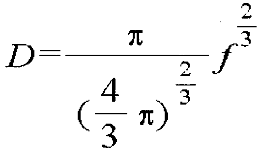
- To determine the critical elastic modulus from the relationship between the void volume fraction, the damage parameter and the elastic modulus, the critical void volume fraction principle is used. The experiments of Brown and Embury and the experiments of Goods and Brown show that the voids start to coalesce together when the void volume fraction (f) ranges from about 0.13 to 0.17, and the void coalescence starts when the void volume fraction (f) is not higher than 0.2. Furthermore, the numerical analysis of Anderson shows that the stable crack growth of a brittle material starts when the void volume fraction (f) ranges from about 0.23 to 0.27. Tebogard used the above-mentioned standard to the cup-corn fracture analysis.
- According to the experiments and analyses, the void volume fraction (fC), at which the void coalescence starts, ranges from 0.13 to 0.17, while the void volume fraction (f F), at which the stable crack growth starts, ranges from 0.23 to 0.27. The two void volume fractions (fC and fF) are used to determine the critical elastic modulus. If the fracture type of a material is known, the damage parameter (D) of the material can be calculated as follows. If the material is a Type-I material, the damage parameter (D) of the material can be determined using a specified value within a range from 0.13 to 0.17, corresponding to the properties of the material, as the void volume fraction in Equation 9. If the material is a Type-II material, the damage parameter (D) can be determined using a specified value within a range from 0.23 to 0.27 as the void volume fraction in Equation 9.
Table 1 Type Material Exact valueKJC(MP am0.5) 0.13 0.15 0.17 0.23 0.25 0.27 Type I SA508 144 117 131 145 SUJ2 111 99 108 117 SKS3 95 111 128 151 S45C 150 115 131 153 Type II X70 380 280 327 385 X65 300 246 301 384 SCM21 261 184 210 244 SUS303 251 199 241 296 - Table 1 shows variation in the evaluated fracture toughness of a material according to variation in the void volume fraction of the material. As illustrated in Table 1, every material has a specific void volume fraction which can be used to evaluate the fracture toughness of the material most precisely (as underlined and bold in the Table). Therefore, it is preferable to evaluate the fracture toughness of the materials after setting the appropriate void volume fractions according to the properties and types of the materials.
- The Type-I materials and the Type-II materials will be described in detail in the description of the experimental results. The damage parameter (D), which was determined for a Type-I material using the void volume fraction (f) within the range from 0.13 to 0.17, is defined as DC, while the damage parameter (D), which was determined for a Type-II material using the void volume fraction (f) within the range from 0.23 to 0.27, is defined as DF. However, if the fracture type of a material is not known, the damage parameter of the material can be determined through iteration, as will be described in Example 2.
- The determined damage parameters are used to calculate the critical elastic moduli (E*) of the materials.

or
- In this case, the value E is the elastic modulus obtained from the analysis of the first unloading curve of a plurality of unloading curves determined through repeated loading and unloading. In other words, the value E is the initial elastic modulus of an undamaged material as described above. Damage to the material caused by voids at the initial stage of indentation is negligible, so that the state of the material at the initial stage of indentation may be considered an undamaged state.
- Thereafter, the characteristic fracture initiation point (h*) of the indentation depth can be calculated from the critical elastic modulus.

-
FIG. 5 is a graph showing the relationship between the effective elastic modulus (E eff) and the indentation depth (h). The relationship between the effective elastic modulus and the indentation depth may be defined as illustrated in the graph of the drawing. If the critical elastic modulus (E*) was determined, the indentation depth corresponding to the critical elastic modulus (E*) can be determined from the characteristic fracture initiation point (h*) of the indentation depth. In this case, the characteristic fracture initiation point must be placed between the points in the graph ofFIG. 5 or must be determined using an extrapolation method, so that the Y-axial component of a line obtained through an ln-ln fitting of curves of the critical elastic modulus and the characteristic fracture initiation point of the indentation depth is defined as A, and the slope of the line obtained through the fitting is defined as B. The characteristic fracture initiation point (h*) of the indentation depth can be determined using Equation 11, the values A and B and the critical elastic modulus (E*) having been obtained using Equation 10. - Thereafter, the fracture toughness of the material can be evaluated using the characteristic fracture initiation point and
Equation 12.
wherein k' represents the slope (Lmax/hmax) of a loading curve, and R is the radius of the indenter.Equation 12 is the equation which is created using only the data obtained from combination ofEquations Equation 12, the value E0 can be determined from the first unloading curve, while the value h* can be determined from the relationship between the critical void volume fraction, the damage parameter and the critical elastic modulus (E*). - Thus, the present invention can evaluate the fracture toughness of a material using the continuous indentation technique including the above-mentioned continuous processes.
- In Example 1, the method of evaluating the fracture toughness of a material, whose fracture type is known, has been described.
- However, in the case of a material whose fracture type is not known, it is impossible to previously determine the critical void volume fraction of the material, so that neither the critical elastic modulus nor the characteristic fracture initiation point of the indentation depth may be determined.
- In the above case, the damage parameter (D0.20) and the critical elastic modulus of the material may be determined using the void volume fraction set to 0.20, which is the average of the void volume fractions of the Type-I materials and the Type-II materials.
- Described in detail, the damage parameter (D0.20) is determined by substitution of 0.20 for the void volume fraction (f) in Equation 9 and the critical elastic modulus is calculated. The critical elastic modulus in the above case is represented by E* im.

- The fracture toughness of the material is calculated by substitution of the critical elastic modulus (E* im) in Equation created by transforming Equation 11 and
Equation 12.

- The plastic zone size (PZS) is calculated from the determined fracture toughness of the material.

wherein YS represents the yield stress of the material determined using the continuous indentation technique. - When the plastic zone size determined using
Equation 16 is not larger than 0.4(m), the material is determined to be Type-I material having a void volume fraction ranging from 0.13 to 0.17. However, when the plastic zone size is larger than 0.4(m), the material is determined to be Type-II material having a void volume fraction ranging from 0.23 to 0.27. Thereafter, the fracture toughness of the material is evaluated using the method described in Example 1. Described in detail, in the method of Example 2, the plastic zone size is determined using a void volume fraction set to 0.20, which is the average of the void volume fraction of the Type-I materials and the void volume fraction of the Type-II materials. Thereafter, the void volume fraction is more precisely determined using the plastic zone size prior to determining the fracture toughness of the material. - The values of critical Crack Tip Opening Displacement (CTOD) are classified into δC, δU and δm, in which the CTOD values of brittle materials are typically represented by δU and δm. While δm is the CTOD value when the maximum load plane is obtained, δU is the CTOD value when a unstable crack growth starts. The relationship between the above-mentioned CTOD values is illustrated in
FIG. 6 and FIG. 7. FIG. 6 and FIG. 7 are graphs illustrating the shapes of curves of indentation load as a function of displacement at a crack tip during a fracture toughness test according to the fracture type.FIG. 6 shows the curve of a δU-type material, whileFIG. 7 shows the curve of a δm-type material. In the present invention, the materials showing a δU-type fracture behavior characteristic of relatively brittle materials are classified as Type-I materials, while the materials showing a δm -type fracture behavior characteristic of relatively soft materials are classified as Type-II materials. - The δU-type materials are the relatively brittle materials and have a smaller resistance to the force that deforms the ligament between voids in comparison to the δm -type materials, so that the load support power of the δU-type materials is quickly reduced just after the void coalescence starts. However, in the δm -type materials, the stable crack growth starts and the load support power is gradually reduced, so that the δm-type materials maintain desired load support power after the void coalescence m starts. Thus, the value fC may be used as the critical void volume fraction of the δU-type material (type-I material), while the value f may be used as the critical void volume fraction of the δM-type material (type-II material). The values fC and fF may be changed to corresponding damage parameters DC and DF using Equation 8. Furthermore, the elastic moduli E*(EC and EF) corresponding to the damage parameters may be determined using
Equation 6. Thus, the value h* is determined from the value h corresponding to the critical elastic modulus, in which the relationship E*=EC is used in the type-I materials, while the relationship E*=EF is used in the type-II materials. -
FIGS. 8 and9 are graphs illustrating the relationship between the effective elastic modulus and the indentation depth according to the fracture type, in whichFIG. 8 shows the relationship of the Type-I material, andFIG. 9 shows the relationship of the Type-II material.FIG. 10 is a graph showing a method of determining the characteristic fracture initiation point of the indentation depth using the effective elastic modulus -indentation depth curve.FIG. 11 is a graph showing a method of determining the characteristic fracture initiation point of the indentation depth using the effective elastic modulus-indentation depth curve and an extrapolation method.FIG. 10 is a graph of a Type-I material having the relationship E*=EC,FIG. 11 is a graph of a Type-II material having the relationship E*=EF. -
FIG. 12 is a graph comparatively illustrating the fracture toughness values evaluated using the continuous indentation technique and CTOD. - As shown in
FIG. 12 , the fracture toughness of thirteen materials, evaluated using the continuous indentation technique which is the nondestructive evaluation technique according to the present invention, is almost equal to the fracture toughness evaluated using the conventional CTOD technique. Thus, the method of evaluating the fracture toughness of a material using the nondestructive evaluation technique according to the present invention can be used as an effective technique substituting for the conventional destructive evaluation technique. - Although the preferred embodiments of the present invention have been disclosed for illustrative purposes, those skilled in the art will appreciate that various modifications, additions and substitutions are possible, without departing from the scope of the invention as disclosed in the accompanying claims.
F is the indentation load,
AC is a contact surface area between the material and the indenter,
R is a radius of the indenter of the continuous indentation tester, and
k' represents a slope (Lmax/hmax) between a maximum indentation load and a maximum indentation depth in an unloading curve.
Claims (10)
- A method of evaluating the fracture toughness of a material using a continuous indentation technique for continuously measuring an indentation load and an indentation depth while repeatedly applying the load to and removing the load from the material, the method comprising the steps of:measuring a stress coefficient, a strain hardening modulus and a yield stress using the continuous indentation technique and calculating a reduced elastic modulus (Er) of the material;calculating an effective elastic modulus (Eeff) from the reduced elastic modulus;determining an initial elastic modulus (E0) from an elastic modulus in a first range of the effective elastic modulus, which was determined using a plurality of unloading curves obtained using the continuous indentation technique;setting a void volume fraction (f) to a specific value within a range from 0.13 to 0.17 when a fracture type of the material is a I-type fracture type, and setting the void volume fraction (f) to a specific value within a range from 0.23 to 0.27 when the fracture type of the material is a II-type fracture type;calculating a damage parameter (D) from the void volume fraction using anequation
 calculating a critical elastic modulus (E*) using the damage parameter;calculating a characteristic fracture initiation point (h*) of the indentation depth using the critical elastic modulus; andcalculating the fracture toughness (KJC) of the material using the characteristic fracture initiation point of the indentation depth using an equation
 wherein k' represents a slope (Lmax/hmax) between a maximum indentation load and a maximum indentation depth in an unloading curve,2ωf is a critical indentation energy,F is the indentation load,AC is a contact surface area between the material and the indenter, andR is a radius of the indenter of the continuous indentation tester.
 - A method of evaluating the fracture toughness of a material using a continuous indentation technique for continuously measuring an indentation load and an indentation depth while repeatedly applying to indentation load to and removing from the material, the method comprising the steps of:measuring a stress coefficient, a strain hardening modulus and a yield stress using the continuous indentation technique and calculating a reduced elastic modulus of the material;calculating an effective elastic modulus from the reduced elastic modulus;determining an initial elastic modulus from an elastic modulus in a first range of the effective elastic modulus, which was determined using a plurality of unloading curves obtained using the continuous indentation technique;setting a void volume fraction to 0.20 when a fracture type of the material is not known;calculating a damage parameter from the void volume fraction using an equation
 calculating a critical elastic modulus (E* im) using the damage parameter;calculating a characteristic fracture initiation point (h*im) of the indentation depth using the critical elastic modulus;calculating a first fracture toughness (KJCim) of the material using the characteristic fracture initiation point of the indentation depth using an equation
 and calculating a plastic zone size (PZS) using the first fracture toughness,wherein k' represents a slope between a maximum indentation load and a maximum indentation depth in an unloading curve,2ωf is a critical indentation energy,F is the indentation load,AC is a contact surface area between the material and the indenter, andR is a radius of the indenter,and wherein, when the plastic zone size is less than or equal to 0.4, the void volume fraction is set to a specific value within a range from 0.13 to 0.17, andwhen the plastic zone size is more than 0.4, the volume fraction is set to a specific value within a range from 0.23 to 0.27 and is used to calculate the fracture toughness as follows:- calculating a damage parameter (D) from the void volume fraction using the equation
 - calculating a critical elastic modulus (E*) using the damage parameter;- calculating a characteristic fracture initiation point (h*) of the indentation depth using the critical elastic modulus,- and calculating the fracture toughness (KJC) of the material using the characteristic fracture initiation point of the indentation depth using the following equation
 wherein 2ωf is a critical indentation energy,F is the indentation load,AC is a contact surface area between the material and the indenter,R is a radius of the indenter of the continuous indentation tester, andk' represents a slope (Lmax/hmax) between a maximum indentation load and a maximum indentation depth in an unloading curve.
 - The method of evaluating the fracture toughness of the material using the continuous indentation technique according to claim 1 or 2, wherein critical indentation energy (2ωf) is calculated using an equation

wherein Ac is a contact surface area between the material and an indenter, F is the indentation load, h is the indentation depth, and h* is the characteristic fracture initiation point of the indentation depth. - The method of evaluating the fracture toughness of the material using the continuous indentation technique according to claim 1 or 2, wherein the reduced elastic modulus is calculated using an equation

wherein S is a slope of the unloading curve. - The method of evaluating the fracture toughness of the material using the continuous indentation technique according to claim 1 or 2, wherein the effective elastic modulus is calculated using an equation

wherein ν and νi are Poisson's ratios of the material and the indenter, respectively, and Ei is an elastic modulus of the indenter. - The method of evaluating the fracture toughness of the material using the continuous indentation technique according to claim 1, wherein the critical elastic modulus is calculated using an equation

- The method of evaluating the fracture toughness of the material using the continuous indentation technique according to claim 1, wherein
the characteristic fracture initiation point of the indentation depth is calculated
wherein A is a Y-axial component of a line obtained through an In-In fitting of curves of the critical elastic modulus (E*) and the characteristic fracture initiation point (h*) of the indentation depth, and B represents a slope of the line obtained through the fitting. - The method of evaluating the fracture toughness of the material using the continuous indentation technique according to claim 2, wherein the critical elastic modulus is calculated using an equation

- The method of evaluating the fracture toughness of the material using the continuous indentation technique according to claim 2, wherein the characteristic fracture initiation point of the indentation depth is calculated using an equation

wherein A is a Y-axial component of a line obtained through an In-In fitting of curves of the critical elastic modulus (E* im) and the characteristic fracture initiation point (h* im) of the indentation depth, and B represents a slope of the line obtained through the fitting. - The method of evaluating the fracture toughness of the material using the continuous indentation technique according to claim 2, wherein the plastic zone size, PZS, is calculated using an equation

wherein YS represents the yield stress of the material which is evaluated using the continuous indentation technique.
Applications Claiming Priority (2)
| Application Number | Priority Date | Filing Date | Title |
|---|---|---|---|
| KR1020040091013A KR100491295B1 (en) | 2004-11-09 | 2004-11-09 | Evaluating method of the fracture toughness using the continuous indentation method |
| PCT/KR2005/003039 WO2006052060A1 (en) | 2004-11-09 | 2005-09-14 | Evaluating method of the fracture toughness using the continuous indentation method |
Publications (3)
| Publication Number | Publication Date |
|---|---|
| EP1815229A1 EP1815229A1 (en) | 2007-08-08 |
| EP1815229A4 EP1815229A4 (en) | 2011-11-30 |
| EP1815229B1 true EP1815229B1 (en) | 2015-06-24 |
Family
ID=36336706
Family Applications (1)
| Application Number | Title | Priority Date | Filing Date |
|---|---|---|---|
| EP05808740.4A Expired - Lifetime EP1815229B1 (en) | 2004-11-09 | 2005-09-14 | Evaluating method of the fracture toughness using the continuous indentation method |
Country Status (5)
| Country | Link |
|---|---|
| US (1) | US7487051B2 (en) |
| EP (1) | EP1815229B1 (en) |
| JP (1) | JP4784774B2 (en) |
| KR (1) | KR100491295B1 (en) |
| WO (1) | WO2006052060A1 (en) |
Cited By (1)
| Publication number | Priority date | Publication date | Assignee | Title |
|---|---|---|---|---|
| CN109459329A (en) * | 2018-10-30 | 2019-03-12 | 中国矿业大学 | Titanium alloy taper impression represents the determination method of strain under a kind of preload condition |
Families Citing this family (28)
| Publication number | Priority date | Publication date | Assignee | Title |
|---|---|---|---|---|
| WO2008007547A1 (en) * | 2006-07-13 | 2008-01-17 | Konica Minolta Opto, Inc. | Method for manufacturing glass substrate, method for manufacturing magnetic disk, and magnetic disk |
| KR101152323B1 (en) * | 2007-02-06 | 2012-06-11 | (주)프론틱스 | Estimation of non-equibiaxial stress using instrumented indentation technique |
| JP4733158B2 (en) * | 2008-04-02 | 2011-07-27 | 株式会社フューチュアテック | Elastic modulus measurement method |
| EP3001172B1 (en) * | 2010-08-06 | 2019-10-09 | YKK Corporation | Cloth evaluation apparatus |
| KR101309046B1 (en) | 2012-04-27 | 2013-09-16 | 한국표준과학연구원 | Measuring method for interfacial adhesion strength of film |
| CN102937492B (en) * | 2012-10-26 | 2014-11-26 | 北京工业大学 | Method for monitoring absolute stress of pre-stress concrete bridge |
| CN102928145B (en) * | 2012-10-26 | 2014-12-10 | 交通运输部公路科学研究所 | Method for detecting absolute stress of prestressed concrete bridge |
| CN103063337B (en) * | 2012-12-17 | 2014-09-10 | 中国建筑第八工程局有限公司 | Measuring method of stresses borne by twice-successively-poured concrete at construction joint |
| KR101497579B1 (en) * | 2013-07-12 | 2015-03-02 | 서강대학교산학협력단 | Evaluation method of indentation fracture toughness in brittle materials based on FEA solutions |
| CN103411833A (en) * | 2013-08-21 | 2013-11-27 | 中国人民解放军装甲兵工程学院 | Instrumentation indentation test method for elastic-plastic parameters of material based on single Vickers pressure head |
| CN103471940B (en) * | 2013-09-27 | 2015-06-10 | 华东理工大学 | Method for determining relation of in-plane and out-of-plane unified constraint and ductility and fracture toughness of material |
| CN104165814B (en) * | 2014-07-23 | 2017-02-01 | 中国人民解放军装甲兵工程学院 | Vickers indentation based material elastoplasticity instrumented indentation test method |
| WO2016045024A1 (en) * | 2014-09-25 | 2016-03-31 | 华东理工大学 | Method for measuring and determining fracture toughness of structural material in high-temperature environment |
| US9557212B2 (en) | 2015-01-06 | 2017-01-31 | Halliburton Energy Services, Inc. | Determining effective elastic modulus of a composite slickline cable |
| KR101707492B1 (en) | 2016-07-27 | 2017-02-17 | (주)프론틱스 | Evaluating Method Of The Fracture Toughness Using Instrumented indentation testing |
| KR101995416B1 (en) * | 2016-12-02 | 2019-09-30 | 주식회사 신영 | Probe pressing device of nondestructive inspection apparatus for spot weld |
| KR102411444B1 (en) * | 2017-10-31 | 2022-06-22 | 대우조선해양 주식회사 | Estimation of absorbed energy of metal specimen |
| CN107907409B (en) * | 2017-11-10 | 2023-01-03 | 中国地质大学(武汉) | Method, equipment and storage equipment for determining rock cracking stress |
| WO2020079699A1 (en) * | 2018-10-16 | 2020-04-23 | M.O Advanced Technologies (Moat) Ltd | Apparatus and method for prediction of tablet defects propensity |
| CN109781540A (en) * | 2019-02-02 | 2019-05-21 | 中南大学 | A kind of rock Loading ami deloading response ratio based on damage strength height method of discrimination |
| CN109855978A (en) * | 2019-02-02 | 2019-06-07 | 中南大学 | A kind of Rock Under Uniaxial Compression based on damage strength has compressed height method of discrimination |
| KR102031195B1 (en) | 2019-02-18 | 2019-10-11 | (주)프론틱스 | Method for Indentation Test Considering Load Cell Deflection |
| CN110501758B (en) * | 2019-07-30 | 2021-06-18 | 东北大学 | A prediction method of longitudinal continuous brittleness index of glutenite reservoir |
| CN111366460B (en) * | 2020-04-10 | 2024-11-05 | 湘潭大学 | Micro-nano indentation testing device and method |
| CN111398019B (en) * | 2020-04-22 | 2021-03-02 | 中国科学院武汉岩土力学研究所 | A quick method for judging the relative size of rock damage under different strain rate loads |
| CN114791385A (en) | 2021-01-26 | 2022-07-26 | 日立金属株式会社 | Method for evaluating embrittlement of amorphous alloy thin strip and test device for evaluating embrittlement of amorphous alloy thin strip |
| CN116879083B (en) * | 2023-06-02 | 2026-03-06 | 同济大学 | A Method for Testing Type I Fracture under Cyclic Thermodynamic Effects |
| CN119830662B (en) * | 2024-12-30 | 2026-02-13 | 达濠市政建设有限公司 | A Crack Prevention Method and System for Segment Joints of Asphalt Concrete Pavement Based on Odor-Free Technology |
Family Cites Families (9)
| Publication number | Priority date | Publication date | Assignee | Title |
|---|---|---|---|---|
| US4582397A (en) * | 1983-03-25 | 1986-04-15 | Chang I Cheng | Diospersive acousto-optic filter |
| US4852397A (en) * | 1988-01-15 | 1989-08-01 | Haggag Fahmy M | Field indentation microprobe for structural integrity evaluation |
| US5602329A (en) * | 1995-08-09 | 1997-02-11 | Massachusetts Institute Of Technology | Method and apparatus for measuring fracture toughness of a material |
| US6134954A (en) * | 1996-04-15 | 2000-10-24 | Massachusetts Institute Of Technology | Depth sensing indentation and methodology for mechanical property measurements |
| US6053034A (en) * | 1998-10-09 | 2000-04-25 | Advanced Micro Devices, Inc. | Method for measuring fracture toughness of thin films |
| FI20001919A0 (en) * | 2000-08-31 | 2000-08-31 | Valtion Teknillinen | Measurement of fracture toughness on a surface by means of a scratch test procedure |
| KR20010016070A (en) | 2000-10-26 | 2001-03-05 | 남충희 | a Hidden Password in the Throwaway Identification System |
| JP2005522690A (en) * | 2002-04-10 | 2005-07-28 | エムティエス・システムズ・コーポレーション | Method and apparatus for determining the properties of a test material by a scratch test |
| AU2002950712A0 (en) * | 2002-08-08 | 2002-09-12 | Monash University | Method and apparatus for determining fracture toughness |
-
2004
- 2004-11-09 KR KR1020040091013A patent/KR100491295B1/en not_active Expired - Fee Related
-
2005
- 2005-09-14 EP EP05808740.4A patent/EP1815229B1/en not_active Expired - Lifetime
- 2005-09-14 US US11/667,229 patent/US7487051B2/en not_active Expired - Lifetime
- 2005-09-14 WO PCT/KR2005/003039 patent/WO2006052060A1/en not_active Ceased
- 2005-09-14 JP JP2007540245A patent/JP4784774B2/en not_active Expired - Fee Related
Cited By (2)
| Publication number | Priority date | Publication date | Assignee | Title |
|---|---|---|---|---|
| CN109459329A (en) * | 2018-10-30 | 2019-03-12 | 中国矿业大学 | Titanium alloy taper impression represents the determination method of strain under a kind of preload condition |
| CN109459329B (en) * | 2018-10-30 | 2020-05-08 | 中国矿业大学 | A method for determining the representative strain of conical indentation in titanium alloys under preloading conditions |
Also Published As
| Publication number | Publication date |
|---|---|
| US7487051B2 (en) | 2009-02-03 |
| US20080010031A1 (en) | 2008-01-10 |
| EP1815229A1 (en) | 2007-08-08 |
| JP2008519963A (en) | 2008-06-12 |
| JP4784774B2 (en) | 2011-10-05 |
| WO2006052060A1 (en) | 2006-05-18 |
| KR100491295B1 (en) | 2005-05-24 |
| EP1815229A4 (en) | 2011-11-30 |
Similar Documents
| Publication | Publication Date | Title |
|---|---|---|
| US7487051B2 (en) | Evaluating method of the fracture toughness using the continuous indentation method | |
| Goto et al. | Determining suitable parameters for inverse estimation of plastic properties based on indentation marks | |
| US7472603B2 (en) | Evaluating method of the residual stress determining method using the continuous indentation method | |
| Sidhom et al. | Fatigue strength improvement of 5083 H11 Al-alloy T-welded joints by shot peening: experimental characterization and predictive approach | |
| US8214162B2 (en) | Estimation of non-equibiaxial stress using instrumented indentation technique | |
| US9513200B1 (en) | Determination of a threshold crack length | |
| Raynaud et al. | Crack growth in the through-thickness direction of hydrided thin-wall Zircaloy sheet | |
| JP2018536868A (en) | Measurement of material properties under local tension through contact mechanics | |
| Wang et al. | Numerical simulation study of combined shot peening and laser shock peening on surface integrity of Ti-6Al-4V titanium alloy | |
| Lin et al. | The effect of strength mis-match on mechanical performance of weld joints | |
| Trantina et al. | Three-dimensional elastic-plastic finite element analysis of small surface cracks | |
| CN105784238A (en) | Method for measuring material surface residual stress and system thereof | |
| Chen et al. | Foreign object damage and fatigue crack threshold: cracking outside shallow indents | |
| Akramin et al. | Analysis of surface crack using various crack growth models | |
| Hoang et al. | Facilitation effect of multiple crack interaction on fatigue life reduction and a quantitative evaluation of interactions factor of two parallel Non-coplanar cracks | |
| Hu et al. | Predicting tensile stretchability of trimmed AA6111-T4 sheets | |
| Ye et al. | Depth-sensing indentation-based studies of surface mechanical behavior and fatigue damage evolution of an austenitic stainless steel subjected to cyclic straining | |
| Ding et al. | Relationship between local strain energy density and fatigue life of riveted Al-Li alloy plate | |
| He et al. | Dynamic response of rectangular plates under repeated impacts from different impactors | |
| Ganjiani et al. | Evaluating the ductile failure characteristics of CuZn30 brass under different stress conditions | |
| Berla et al. | A physically based model for indenter tip shape calibration for nanoindentation | |
| Villeneuve et al. | Dynamic finite element analysis simulation of the terminal crimping process | |
| Gaither et al. | Deformation and fracture of single-crystal silicon theta-like specimens | |
| Arnaud et al. | Fretting tests for cyclic plastic law identification: Application to a 1XXX aluminium crossed wire contact | |
| Lamouroux et al. | Detailed model of spot-welded joints to simulate the failure of car assemblies |
Legal Events
| Date | Code | Title | Description |
|---|---|---|---|
| PUAI | Public reference made under article 153(3) epc to a published international application that has entered the european phase |
Free format text: ORIGINAL CODE: 0009012 |
|
| 17P | Request for examination filed |
Effective date: 20070529 |
|
| AK | Designated contracting states |
Kind code of ref document: A1 Designated state(s): AT BE BG CH CY CZ DE DK EE ES FI FR GB GR HU IE IS IT LI LT LU LV MC NL PL PT RO SE SI SK TR |
|
| RIN1 | Information on inventor provided before grant (corrected) |
Inventor name: SEO, YANG-WON Inventor name: CHOI, YEOL Inventor name: LEE, JUNG-SUKSEOUL NATIONAL UNIVERSITY Inventor name: KIM, KWANG-HOSEOUL NATIONAL UNIVERSITY |
|
| DAX | Request for extension of the european patent (deleted) | ||
| A4 | Supplementary search report drawn up and despatched |
Effective date: 20111028 |
|
| RIC1 | Information provided on ipc code assigned before grant |
Ipc: G01N 3/42 20060101AFI20111024BHEP |
|
| RIC1 | Information provided on ipc code assigned before grant |
Ipc: G01N 3/42 20060101AFI20140227BHEP |
|
| GRAP | Despatch of communication of intention to grant a patent |
Free format text: ORIGINAL CODE: EPIDOSNIGR1 |
|
| INTG | Intention to grant announced |
Effective date: 20150122 |
|
| RAP1 | Party data changed (applicant data changed or rights of an application transferred) |
Owner name: FRONTICS, INC. |
|
| RIN1 | Information on inventor provided before grant (corrected) |
Inventor name: CHOI, YEOL Inventor name: LEE, JUNG-SUK Inventor name: KIM, KWANG-HO Inventor name: SEO, YANG-WON |
|
| GRAS | Grant fee paid |
Free format text: ORIGINAL CODE: EPIDOSNIGR3 |
|
| GRAA | (expected) grant |
Free format text: ORIGINAL CODE: 0009210 |
|
| AK | Designated contracting states |
Kind code of ref document: B1 Designated state(s): AT BE BG CH CY CZ DE DK EE ES FI FR GB GR HU IE IS IT LI LT LU LV MC NL PL PT RO SE SI SK TR |
|
| REG | Reference to a national code |
Ref country code: GB Ref legal event code: FG4D |
|
| REG | Reference to a national code |
Ref country code: CH Ref legal event code: EP |
|
| REG | Reference to a national code |
Ref country code: AT Ref legal event code: REF Ref document number: 733115 Country of ref document: AT Kind code of ref document: T Effective date: 20150715 |
|
| REG | Reference to a national code |
Ref country code: IE Ref legal event code: FG4D |
|
| REG | Reference to a national code |
Ref country code: DE Ref legal event code: R096 Ref document number: 602005046822 Country of ref document: DE |
|
| PG25 | Lapsed in a contracting state [announced via postgrant information from national office to epo] |
Ref country code: LT Free format text: LAPSE BECAUSE OF FAILURE TO SUBMIT A TRANSLATION OF THE DESCRIPTION OR TO PAY THE FEE WITHIN THE PRESCRIBED TIME-LIMIT Effective date: 20150624 Ref country code: FI Free format text: LAPSE BECAUSE OF FAILURE TO SUBMIT A TRANSLATION OF THE DESCRIPTION OR TO PAY THE FEE WITHIN THE PRESCRIBED TIME-LIMIT Effective date: 20150624 |
|
| REG | Reference to a national code |
Ref country code: CH Ref legal event code: NV Representative=s name: RIEDERER HASLER AND PARTNER PATENTANWAELTE AG, LI |
|
| REG | Reference to a national code |
Ref country code: AT Ref legal event code: MK05 Ref document number: 733115 Country of ref document: AT Kind code of ref document: T Effective date: 20150624 |
|
| REG | Reference to a national code |
Ref country code: LT Ref legal event code: MG4D |
|
| PG25 | Lapsed in a contracting state [announced via postgrant information from national office to epo] |
Ref country code: LV Free format text: LAPSE BECAUSE OF FAILURE TO SUBMIT A TRANSLATION OF THE DESCRIPTION OR TO PAY THE FEE WITHIN THE PRESCRIBED TIME-LIMIT Effective date: 20150624 Ref country code: GR Free format text: LAPSE BECAUSE OF FAILURE TO SUBMIT A TRANSLATION OF THE DESCRIPTION OR TO PAY THE FEE WITHIN THE PRESCRIBED TIME-LIMIT Effective date: 20150925 Ref country code: BG Free format text: LAPSE BECAUSE OF FAILURE TO SUBMIT A TRANSLATION OF THE DESCRIPTION OR TO PAY THE FEE WITHIN THE PRESCRIBED TIME-LIMIT Effective date: 20150924 |
|
| REG | Reference to a national code |
Ref country code: NL Ref legal event code: MP Effective date: 20150624 |
|
| PG25 | Lapsed in a contracting state [announced via postgrant information from national office to epo] |
Ref country code: EE Free format text: LAPSE BECAUSE OF FAILURE TO SUBMIT A TRANSLATION OF THE DESCRIPTION OR TO PAY THE FEE WITHIN THE PRESCRIBED TIME-LIMIT Effective date: 20150624 |
|
| PG25 | Lapsed in a contracting state [announced via postgrant information from national office to epo] |
Ref country code: PL Free format text: LAPSE BECAUSE OF FAILURE TO SUBMIT A TRANSLATION OF THE DESCRIPTION OR TO PAY THE FEE WITHIN THE PRESCRIBED TIME-LIMIT Effective date: 20150624 Ref country code: RO Free format text: LAPSE BECAUSE OF NON-PAYMENT OF DUE FEES Effective date: 20150624 Ref country code: AT Free format text: LAPSE BECAUSE OF FAILURE TO SUBMIT A TRANSLATION OF THE DESCRIPTION OR TO PAY THE FEE WITHIN THE PRESCRIBED TIME-LIMIT Effective date: 20150624 Ref country code: IS Free format text: LAPSE BECAUSE OF FAILURE TO SUBMIT A TRANSLATION OF THE DESCRIPTION OR TO PAY THE FEE WITHIN THE PRESCRIBED TIME-LIMIT Effective date: 20151024 Ref country code: SK Free format text: LAPSE BECAUSE OF FAILURE TO SUBMIT A TRANSLATION OF THE DESCRIPTION OR TO PAY THE FEE WITHIN THE PRESCRIBED TIME-LIMIT Effective date: 20150624 Ref country code: CZ Free format text: LAPSE BECAUSE OF FAILURE TO SUBMIT A TRANSLATION OF THE DESCRIPTION OR TO PAY THE FEE WITHIN THE PRESCRIBED TIME-LIMIT Effective date: 20150624 Ref country code: ES Free format text: LAPSE BECAUSE OF FAILURE TO SUBMIT A TRANSLATION OF THE DESCRIPTION OR TO PAY THE FEE WITHIN THE PRESCRIBED TIME-LIMIT Effective date: 20150624 Ref country code: PT Free format text: LAPSE BECAUSE OF FAILURE TO SUBMIT A TRANSLATION OF THE DESCRIPTION OR TO PAY THE FEE WITHIN THE PRESCRIBED TIME-LIMIT Effective date: 20151026 |
|
| REG | Reference to a national code |
Ref country code: DE Ref legal event code: R097 Ref document number: 602005046822 Country of ref document: DE |
|
| PG25 | Lapsed in a contracting state [announced via postgrant information from national office to epo] |
Ref country code: DK Free format text: LAPSE BECAUSE OF FAILURE TO SUBMIT A TRANSLATION OF THE DESCRIPTION OR TO PAY THE FEE WITHIN THE PRESCRIBED TIME-LIMIT Effective date: 20150624 Ref country code: IT Free format text: LAPSE BECAUSE OF FAILURE TO SUBMIT A TRANSLATION OF THE DESCRIPTION OR TO PAY THE FEE WITHIN THE PRESCRIBED TIME-LIMIT Effective date: 20150624 Ref country code: MC Free format text: LAPSE BECAUSE OF FAILURE TO SUBMIT A TRANSLATION OF THE DESCRIPTION OR TO PAY THE FEE WITHIN THE PRESCRIBED TIME-LIMIT Effective date: 20150624 Ref country code: LU Free format text: LAPSE BECAUSE OF FAILURE TO SUBMIT A TRANSLATION OF THE DESCRIPTION OR TO PAY THE FEE WITHIN THE PRESCRIBED TIME-LIMIT Effective date: 20150914 |
|
| PLBE | No opposition filed within time limit |
Free format text: ORIGINAL CODE: 0009261 |
|
| STAA | Information on the status of an ep patent application or granted ep patent |
Free format text: STATUS: NO OPPOSITION FILED WITHIN TIME LIMIT |
|
| 26N | No opposition filed |
Effective date: 20160329 |
|
| REG | Reference to a national code |
Ref country code: IE Ref legal event code: MM4A |
|
| PG25 | Lapsed in a contracting state [announced via postgrant information from national office to epo] |
Ref country code: IE Free format text: LAPSE BECAUSE OF NON-PAYMENT OF DUE FEES Effective date: 20150914 |
|
| PG25 | Lapsed in a contracting state [announced via postgrant information from national office to epo] |
Ref country code: SI Free format text: LAPSE BECAUSE OF FAILURE TO SUBMIT A TRANSLATION OF THE DESCRIPTION OR TO PAY THE FEE WITHIN THE PRESCRIBED TIME-LIMIT Effective date: 20150624 |
|
| REG | Reference to a national code |
Ref country code: FR Ref legal event code: PLFP Year of fee payment: 12 |
|
| PG25 | Lapsed in a contracting state [announced via postgrant information from national office to epo] |
Ref country code: BE Free format text: LAPSE BECAUSE OF FAILURE TO SUBMIT A TRANSLATION OF THE DESCRIPTION OR TO PAY THE FEE WITHIN THE PRESCRIBED TIME-LIMIT Effective date: 20150624 |
|
| PG25 | Lapsed in a contracting state [announced via postgrant information from national office to epo] |
Ref country code: HU Free format text: LAPSE BECAUSE OF FAILURE TO SUBMIT A TRANSLATION OF THE DESCRIPTION OR TO PAY THE FEE WITHIN THE PRESCRIBED TIME-LIMIT; INVALID AB INITIO Effective date: 20050914 |
|
| PG25 | Lapsed in a contracting state [announced via postgrant information from national office to epo] |
Ref country code: NL Free format text: LAPSE BECAUSE OF FAILURE TO SUBMIT A TRANSLATION OF THE DESCRIPTION OR TO PAY THE FEE WITHIN THE PRESCRIBED TIME-LIMIT Effective date: 20150624 Ref country code: SE Free format text: LAPSE BECAUSE OF FAILURE TO SUBMIT A TRANSLATION OF THE DESCRIPTION OR TO PAY THE FEE WITHIN THE PRESCRIBED TIME-LIMIT Effective date: 20150624 Ref country code: CY Free format text: LAPSE BECAUSE OF FAILURE TO SUBMIT A TRANSLATION OF THE DESCRIPTION OR TO PAY THE FEE WITHIN THE PRESCRIBED TIME-LIMIT Effective date: 20150624 |
|
| PG25 | Lapsed in a contracting state [announced via postgrant information from national office to epo] |
Ref country code: TR Free format text: LAPSE BECAUSE OF FAILURE TO SUBMIT A TRANSLATION OF THE DESCRIPTION OR TO PAY THE FEE WITHIN THE PRESCRIBED TIME-LIMIT Effective date: 20150624 |
|
| REG | Reference to a national code |
Ref country code: FR Ref legal event code: PLFP Year of fee payment: 13 |
|
| REG | Reference to a national code |
Ref country code: FR Ref legal event code: PLFP Year of fee payment: 14 |
|
| P01 | Opt-out of the competence of the unified patent court (upc) registered |
Effective date: 20230622 |
|
| PGFP | Annual fee paid to national office [announced via postgrant information from national office to epo] |
Ref country code: DE Payment date: 20240923 Year of fee payment: 20 |
|
| PGFP | Annual fee paid to national office [announced via postgrant information from national office to epo] |
Ref country code: FR Payment date: 20240927 Year of fee payment: 20 |
|
| PGFP | Annual fee paid to national office [announced via postgrant information from national office to epo] |
Ref country code: GB Payment date: 20241024 Year of fee payment: 20 |
|
| PGFP | Annual fee paid to national office [announced via postgrant information from national office to epo] |
Ref country code: CH Payment date: 20241025 Year of fee payment: 20 |
|
| REG | Reference to a national code |
Ref country code: DE Ref legal event code: R071 Ref document number: 602005046822 Country of ref document: DE |
|
| REG | Reference to a national code |
Ref country code: CH Ref legal event code: PL |
|
| REG | Reference to a national code |
Ref country code: GB Ref legal event code: PE20 Expiry date: 20250913 |
|
| REG | Reference to a national code |
Ref country code: DE Ref legal event code: R082 Ref document number: 602005046822 Country of ref document: DE Representative=s name: PUSCHMANN BORCHERT KAISER KLETTNER PATENTANWAE, DE |