EP1814615B1 - Injection device - Google Patents
Injection device Download PDFInfo
- Publication number
- EP1814615B1 EP1814615B1 EP05808428.6A EP05808428A EP1814615B1 EP 1814615 B1 EP1814615 B1 EP 1814615B1 EP 05808428 A EP05808428 A EP 05808428A EP 1814615 B1 EP1814615 B1 EP 1814615B1
- Authority
- EP
- European Patent Office
- Prior art keywords
- needle shield
- plunger
- tubular member
- ledges
- needle
- Prior art date
- Legal status (The legal status is an assumption and is not a legal conclusion. Google has not performed a legal analysis and makes no representation as to the accuracy of the status listed.)
- Expired - Lifetime
Links
Images













Classifications
-
- A—HUMAN NECESSITIES
- A61—MEDICAL OR VETERINARY SCIENCE; HYGIENE
- A61M—DEVICES FOR INTRODUCING MEDIA INTO, OR ONTO, THE BODY; DEVICES FOR TRANSDUCING BODY MEDIA OR FOR TAKING MEDIA FROM THE BODY; DEVICES FOR PRODUCING OR ENDING SLEEP OR STUPOR
- A61M5/00—Devices for bringing media into the body in a subcutaneous, intra-vascular or intramuscular way; Accessories therefor, e.g. filling or cleaning devices, arm-rests
- A61M5/178—Syringes
- A61M5/31—Details
- A61M5/315—Pistons; Piston-rods; Guiding, blocking or restricting the movement of the rod or piston; Appliances on the rod for facilitating dosing ; Dosing mechanisms
- A61M5/31565—Administration mechanisms, i.e. constructional features, modes of administering a dose
- A61M5/31576—Constructional features or modes of drive mechanisms for piston rods
- A61M5/31583—Constructional features or modes of drive mechanisms for piston rods based on rotational translation, i.e. movement of piston rod is caused by relative rotation between the user activated actuator and the piston rod
- A61M5/31586—Constructional features or modes of drive mechanisms for piston rods based on rotational translation, i.e. movement of piston rod is caused by relative rotation between the user activated actuator and the piston rod performed by rotationally moving or pivoted actuator, e.g. an injection lever or handle
-
- A—HUMAN NECESSITIES
- A61—MEDICAL OR VETERINARY SCIENCE; HYGIENE
- A61M—DEVICES FOR INTRODUCING MEDIA INTO, OR ONTO, THE BODY; DEVICES FOR TRANSDUCING BODY MEDIA OR FOR TAKING MEDIA FROM THE BODY; DEVICES FOR PRODUCING OR ENDING SLEEP OR STUPOR
- A61M15/00—Inhalators
- A61M15/0065—Inhalators with dosage or measuring devices
- A61M15/0066—Inhalators with dosage or measuring devices with means for varying the dose size
-
- A—HUMAN NECESSITIES
- A61—MEDICAL OR VETERINARY SCIENCE; HYGIENE
- A61M—DEVICES FOR INTRODUCING MEDIA INTO, OR ONTO, THE BODY; DEVICES FOR TRANSDUCING BODY MEDIA OR FOR TAKING MEDIA FROM THE BODY; DEVICES FOR PRODUCING OR ENDING SLEEP OR STUPOR
- A61M5/00—Devices for bringing media into the body in a subcutaneous, intra-vascular or intramuscular way; Accessories therefor, e.g. filling or cleaning devices, arm-rests
- A61M5/178—Syringes
- A61M5/19—Syringes having more than one chamber, e.g. including a manifold coupling two parallelly aligned syringes through separate channels to a common discharge assembly
-
- A—HUMAN NECESSITIES
- A61—MEDICAL OR VETERINARY SCIENCE; HYGIENE
- A61M—DEVICES FOR INTRODUCING MEDIA INTO, OR ONTO, THE BODY; DEVICES FOR TRANSDUCING BODY MEDIA OR FOR TAKING MEDIA FROM THE BODY; DEVICES FOR PRODUCING OR ENDING SLEEP OR STUPOR
- A61M5/00—Devices for bringing media into the body in a subcutaneous, intra-vascular or intramuscular way; Accessories therefor, e.g. filling or cleaning devices, arm-rests
- A61M5/178—Syringes
- A61M5/20—Automatic syringes, e.g. with automatically actuated piston rod, with automatic needle injection, filling automatically
- A61M5/2033—Spring-loaded one-shot injectors with or without automatic needle insertion
-
- A—HUMAN NECESSITIES
- A61—MEDICAL OR VETERINARY SCIENCE; HYGIENE
- A61M—DEVICES FOR INTRODUCING MEDIA INTO, OR ONTO, THE BODY; DEVICES FOR TRANSDUCING BODY MEDIA OR FOR TAKING MEDIA FROM THE BODY; DEVICES FOR PRODUCING OR ENDING SLEEP OR STUPOR
- A61M5/00—Devices for bringing media into the body in a subcutaneous, intra-vascular or intramuscular way; Accessories therefor, e.g. filling or cleaning devices, arm-rests
- A61M5/178—Syringes
- A61M5/31—Details
- A61M5/3146—Priming, e.g. purging, reducing backlash or clearance
-
- A—HUMAN NECESSITIES
- A61—MEDICAL OR VETERINARY SCIENCE; HYGIENE
- A61M—DEVICES FOR INTRODUCING MEDIA INTO, OR ONTO, THE BODY; DEVICES FOR TRANSDUCING BODY MEDIA OR FOR TAKING MEDIA FROM THE BODY; DEVICES FOR PRODUCING OR ENDING SLEEP OR STUPOR
- A61M5/00—Devices for bringing media into the body in a subcutaneous, intra-vascular or intramuscular way; Accessories therefor, e.g. filling or cleaning devices, arm-rests
- A61M5/178—Syringes
- A61M5/31—Details
- A61M5/315—Pistons; Piston-rods; Guiding, blocking or restricting the movement of the rod or piston; Appliances on the rod for facilitating dosing ; Dosing mechanisms
- A61M5/31501—Means for blocking or restricting the movement of the rod or piston
- A61M5/31505—Integral with the syringe barrel, i.e. connected to the barrel so as to make up a single complete piece or unit
-
- A—HUMAN NECESSITIES
- A61—MEDICAL OR VETERINARY SCIENCE; HYGIENE
- A61M—DEVICES FOR INTRODUCING MEDIA INTO, OR ONTO, THE BODY; DEVICES FOR TRANSDUCING BODY MEDIA OR FOR TAKING MEDIA FROM THE BODY; DEVICES FOR PRODUCING OR ENDING SLEEP OR STUPOR
- A61M5/00—Devices for bringing media into the body in a subcutaneous, intra-vascular or intramuscular way; Accessories therefor, e.g. filling or cleaning devices, arm-rests
- A61M5/178—Syringes
- A61M5/31—Details
- A61M5/315—Pistons; Piston-rods; Guiding, blocking or restricting the movement of the rod or piston; Appliances on the rod for facilitating dosing ; Dosing mechanisms
- A61M5/31525—Dosing
-
- A—HUMAN NECESSITIES
- A61—MEDICAL OR VETERINARY SCIENCE; HYGIENE
- A61M—DEVICES FOR INTRODUCING MEDIA INTO, OR ONTO, THE BODY; DEVICES FOR TRANSDUCING BODY MEDIA OR FOR TAKING MEDIA FROM THE BODY; DEVICES FOR PRODUCING OR ENDING SLEEP OR STUPOR
- A61M5/00—Devices for bringing media into the body in a subcutaneous, intra-vascular or intramuscular way; Accessories therefor, e.g. filling or cleaning devices, arm-rests
- A61M5/178—Syringes
- A61M5/31—Details
- A61M5/315—Pistons; Piston-rods; Guiding, blocking or restricting the movement of the rod or piston; Appliances on the rod for facilitating dosing ; Dosing mechanisms
- A61M5/31533—Dosing mechanisms, i.e. setting a dose
- A61M5/31545—Setting modes for dosing
- A61M5/31548—Mechanically operated dose setting member
- A61M5/3155—Mechanically operated dose setting member by rotational movement of dose setting member, e.g. during setting or filling of a syringe
- A61M5/31553—Mechanically operated dose setting member by rotational movement of dose setting member, e.g. during setting or filling of a syringe without axial movement of dose setting member
-
- A—HUMAN NECESSITIES
- A61—MEDICAL OR VETERINARY SCIENCE; HYGIENE
- A61M—DEVICES FOR INTRODUCING MEDIA INTO, OR ONTO, THE BODY; DEVICES FOR TRANSDUCING BODY MEDIA OR FOR TAKING MEDIA FROM THE BODY; DEVICES FOR PRODUCING OR ENDING SLEEP OR STUPOR
- A61M5/00—Devices for bringing media into the body in a subcutaneous, intra-vascular or intramuscular way; Accessories therefor, e.g. filling or cleaning devices, arm-rests
- A61M5/178—Syringes
- A61M5/31—Details
- A61M5/32—Needles; Details of needles pertaining to their connection with syringe or hub; Accessories for bringing the needle into, or holding the needle on, the body; Devices for protection of needles
- A61M5/3202—Devices for protection of the needle before use, e.g. caps
-
- A—HUMAN NECESSITIES
- A61—MEDICAL OR VETERINARY SCIENCE; HYGIENE
- A61M—DEVICES FOR INTRODUCING MEDIA INTO, OR ONTO, THE BODY; DEVICES FOR TRANSDUCING BODY MEDIA OR FOR TAKING MEDIA FROM THE BODY; DEVICES FOR PRODUCING OR ENDING SLEEP OR STUPOR
- A61M5/00—Devices for bringing media into the body in a subcutaneous, intra-vascular or intramuscular way; Accessories therefor, e.g. filling or cleaning devices, arm-rests
- A61M5/178—Syringes
- A61M5/31—Details
- A61M5/32—Needles; Details of needles pertaining to their connection with syringe or hub; Accessories for bringing the needle into, or holding the needle on, the body; Devices for protection of needles
- A61M5/3205—Apparatus for removing or disposing of used needles or syringes, e.g. containers; Means for protection against accidental injuries from used needles
- A61M5/321—Means for protection against accidental injuries by used needles
- A61M5/3243—Means for protection against accidental injuries by used needles being axially-extensible, e.g. protective sleeves coaxially slidable on the syringe barrel
- A61M5/3257—Semi-automatic sleeve extension, i.e. in which triggering of the sleeve extension requires a deliberate action by the user, e.g. manual release of spring-biased extension means
-
- A—HUMAN NECESSITIES
- A61—MEDICAL OR VETERINARY SCIENCE; HYGIENE
- A61M—DEVICES FOR INTRODUCING MEDIA INTO, OR ONTO, THE BODY; DEVICES FOR TRANSDUCING BODY MEDIA OR FOR TAKING MEDIA FROM THE BODY; DEVICES FOR PRODUCING OR ENDING SLEEP OR STUPOR
- A61M5/00—Devices for bringing media into the body in a subcutaneous, intra-vascular or intramuscular way; Accessories therefor, e.g. filling or cleaning devices, arm-rests
- A61M5/178—Syringes
- A61M5/31—Details
- A61M5/32—Needles; Details of needles pertaining to their connection with syringe or hub; Accessories for bringing the needle into, or holding the needle on, the body; Devices for protection of needles
- A61M5/3205—Apparatus for removing or disposing of used needles or syringes, e.g. containers; Means for protection against accidental injuries from used needles
- A61M5/321—Means for protection against accidental injuries by used needles
- A61M5/3243—Means for protection against accidental injuries by used needles being axially-extensible, e.g. protective sleeves coaxially slidable on the syringe barrel
- A61M5/3271—Means for protection against accidental injuries by used needles being axially-extensible, e.g. protective sleeves coaxially slidable on the syringe barrel with guiding tracks for controlled sliding of needle protective sleeve from needle exposing to needle covering position
- A61M5/3272—Means for protection against accidental injuries by used needles being axially-extensible, e.g. protective sleeves coaxially slidable on the syringe barrel with guiding tracks for controlled sliding of needle protective sleeve from needle exposing to needle covering position having projections following labyrinth paths
-
- A—HUMAN NECESSITIES
- A61—MEDICAL OR VETERINARY SCIENCE; HYGIENE
- A61M—DEVICES FOR INTRODUCING MEDIA INTO, OR ONTO, THE BODY; DEVICES FOR TRANSDUCING BODY MEDIA OR FOR TAKING MEDIA FROM THE BODY; DEVICES FOR PRODUCING OR ENDING SLEEP OR STUPOR
- A61M5/00—Devices for bringing media into the body in a subcutaneous, intra-vascular or intramuscular way; Accessories therefor, e.g. filling or cleaning devices, arm-rests
- A61M5/178—Syringes
- A61M5/20—Automatic syringes, e.g. with automatically actuated piston rod, with automatic needle injection, filling automatically
- A61M2005/2006—Having specific accessories
- A61M2005/2013—Having specific accessories triggering of discharging means by contact of injector with patient body
-
- A—HUMAN NECESSITIES
- A61—MEDICAL OR VETERINARY SCIENCE; HYGIENE
- A61M—DEVICES FOR INTRODUCING MEDIA INTO, OR ONTO, THE BODY; DEVICES FOR TRANSDUCING BODY MEDIA OR FOR TAKING MEDIA FROM THE BODY; DEVICES FOR PRODUCING OR ENDING SLEEP OR STUPOR
- A61M5/00—Devices for bringing media into the body in a subcutaneous, intra-vascular or intramuscular way; Accessories therefor, e.g. filling or cleaning devices, arm-rests
- A61M5/178—Syringes
- A61M5/24—Ampoule syringes, i.e. syringes with needle for use in combination with replaceable ampoules or carpules, e.g. automatic
-
- A—HUMAN NECESSITIES
- A61—MEDICAL OR VETERINARY SCIENCE; HYGIENE
- A61M—DEVICES FOR INTRODUCING MEDIA INTO, OR ONTO, THE BODY; DEVICES FOR TRANSDUCING BODY MEDIA OR FOR TAKING MEDIA FROM THE BODY; DEVICES FOR PRODUCING OR ENDING SLEEP OR STUPOR
- A61M5/00—Devices for bringing media into the body in a subcutaneous, intra-vascular or intramuscular way; Accessories therefor, e.g. filling or cleaning devices, arm-rests
- A61M5/178—Syringes
- A61M5/31—Details
- A61M5/315—Pistons; Piston-rods; Guiding, blocking or restricting the movement of the rod or piston; Appliances on the rod for facilitating dosing ; Dosing mechanisms
- A61M5/31533—Dosing mechanisms, i.e. setting a dose
- A61M5/31545—Setting modes for dosing
- A61M5/31548—Mechanically operated dose setting member
- A61M5/3156—Mechanically operated dose setting member using volume steps only adjustable in discrete intervals, i.e. individually distinct intervals
-
- A—HUMAN NECESSITIES
- A61—MEDICAL OR VETERINARY SCIENCE; HYGIENE
- A61M—DEVICES FOR INTRODUCING MEDIA INTO, OR ONTO, THE BODY; DEVICES FOR TRANSDUCING BODY MEDIA OR FOR TAKING MEDIA FROM THE BODY; DEVICES FOR PRODUCING OR ENDING SLEEP OR STUPOR
- A61M5/00—Devices for bringing media into the body in a subcutaneous, intra-vascular or intramuscular way; Accessories therefor, e.g. filling or cleaning devices, arm-rests
- A61M5/178—Syringes
- A61M5/31—Details
- A61M5/315—Pistons; Piston-rods; Guiding, blocking or restricting the movement of the rod or piston; Appliances on the rod for facilitating dosing ; Dosing mechanisms
- A61M5/31533—Dosing mechanisms, i.e. setting a dose
- A61M5/31545—Setting modes for dosing
- A61M5/31548—Mechanically operated dose setting member
- A61M5/31563—Mechanically operated dose setting member interacting with a displaceable stop member
Definitions
- the present invention relates to delivery devices such as injectors, mouth or nasal inhalers, powder or aerosol inhalers, nebulizers and the like.
- cover or protection means that are manually or automatically activated in order to protect persons from for example an injection needle, in particular after use.
- enclosures such as cartridges, 25 ampoules or syringes containing medicament in liquid form.
- a small amount of air is very often entrapped in the container, which air has to be removed before delivery.
- Some devices are of multi-chamber type where one component is powder and the other is liquid or two liquids or more liquids and powder chambers.
- the dose to be delivered is so small that it is not practically possible to provide such a small compartment in the enclosure or to provide a device that is capable of expelling the content from such a small compartment.
- WO2004/028598 relates to an injection device comprising a first and a second tubular member and a plunger that is arranged with a number of outwardly extending stop members.
- the device is activated by pressing the device/needle shield against and injection site to trigger the activation mechanism.
- the device does not disclose a dosing mechanism.
- European patent application No. 298 067 discloses an injection device where mixing of two components in a cartridge and the subsequent deaeration is performed by screwing an upper and a lower part of the device. This solution requires quite a lot of manual handling by the user in order to get the device ready for injection.
- EP 298 067 further discloses a dose setting feature of the device, however without any specifications regarding the manner this can be performed.
- the aim of the present invention is to provide an injection device that is easy and safe to handle, based on a method for designing various features and various combinations.
- a device for controlling and performing functions of a device for delivery of medicament comprising a number of components arranged to co-act with each other, comprising co-operating means, at least some of them arranged on the surfaces of the components, comprising guide means capable of guiding the relative movement between two co-acting components for controlling and performing at least one function.
- the guide means comprises mechanical members like ridges, ledges or groove having side surfaces arranged on one component, against which protrusions, ridges, ledges or grooves on another component are in contact for guiding the relative movement.
- the co-operating means further comprises locking means capable of locking the co-acting components relative each other at pre-defined mutual positions.
- the locking means comprises grooves, cut-outs, recesses protrusions on one component, co-operating with protrusions, ridges, ledges or recesses on another component for locking the movement between the co-acting components.
- the co-operating means comprises holding means, capable of holding two co-acting components in mutual positions in a first direction until one or more of other components are moved a certain amount in a direction deviating from said first direction, wherein the co-acting components are released from each other.
- the holding means comprises ledges, ridges, recesses on one component, co-acting with protrusions, ledges ridges or recesses on another component.
- At least one component is arranged as a generally tubular member, the inner and / or outer surfaces of which are arranged with said co-operating means.
- co-operating means on at least two, preferably more, co-acting components for guiding their relative movement, the interaction between the components can be simplified, especially in view of designing and manufacturing the device and still have a reliable function.
- the co-operating means can be formed as locking members capable of locking the co-acting components.
- the co-operating means can be designed to hold the components in pre-defined positions relative each other.
- the co-operating means are preferably mechanical members in the form of grooves, ledger ridges, recesses, cut-outs, protrusions, threads and the like that are designed to guide, lock and / or hold the co-acting components in their movement relative each other.
- At least one of the components is preferably tubular, having co-operating means arranged on its surfaces, which could be inner, outer and edge surfaces.
- co-operating means arranged on its surfaces, which could be inner, outer and edge surfaces.
- the possibilities with the principle according to the invention are numerous since the number of surfaces that are available and the types and design of co-operating means possible are vast, almost all types of movements and functions are feasible, with a reduced number of components for the device compared to the state of the art. This could be achieved without reducing the overall functionality of the device. Rather on the contrary, since fewer components generally are needed for performing a number of functions, the interplay between components, and thus the dependency that each component in a chain or series is designed so that the desired function is obtained, is reduced.
- the novel feature of the invention is the manner of controlling different functions of a device such as an injecting device.
- a device such as an injecting device.
- such devices may have several functions included, which functions are more or less automated and may be working in series or in parallel with each other.
- These functions may include priming of the medicament in liquid form prior to injection, mixing of medicament for multi-compartment ampoules or syringes, penetration of a needle into the body of a patient, injection of the medicament in the body of the patient, withdrawal of needle after injection, advancing of a needle shield for protection of the needle and subsequent locking of the needle shield. Further features may include setting of specific doses, delivery of specific doses, etc.
- the different features and functions entail co-operation and / co-action between different components of the device such as pistons, sleeves, springs, locking hooks, threaded parts and the like.
- co-operating means arranged on co-acting components of the device for enabling these functions.
- the co-operating means comprise mechanical members like cams 10, ridges 12, protrusions 14, recesses 16, slots and grooves 18, ledges 20, Fig. 1 , threads 21, Fig. 3a , and the like, arranged on one or several surfaces of these components.
- These mechanical members arranged on one component co-operate with mechanical members 22 on another component, which components are arranged to co-act with each other in order to perform a certain function, Fig 2 .
- the cooperating means could be used to guide a movement between two co-acting components, like is shown in Fig. 4a .
- the groove 18 only allows movement in one direction, 24, until a protrusion or pin 26 of the other component has moved from an initial position 26 1 to a certain position 26 2 .
- the protrusion may be flexible and the groove may be arranged with a ramp 28, whereby, when the protrusion has passed the ramp, it cannot move back to the initial position.
- the groove now allows a movement in the direction of the arrow 30 until the protrusion has moved to a position 26 3 when it is allowed to again move in the direction parallel to the first direction 24 to a position 26 4 .
- the co-operating means be arranged on a surface, but it is also possible to arrange them on edge parts 32, Figs. 3a - c of the co-acting components. They can be formed as slots that have either straight walls 34 or ramped walls 36 in relation to the direction of the edge. They may further be arranged on one side only, Fig. 3c , or on both sides, Fig 3b , in the latter case if there are more than two co-operating components.
- the edge parts can be formed step-like 38 as shown in Fig. 6a for providing certain defined distances d that a member 40 on another component is able to move, e.g. for delivering specific doses of medicament.
- ledges 42, Figs. 5 and 6 on the edges of one co-acting component co-operating with another component to form a mutual fixed relationship between the two, Fig. 6 a-c .
- the ledge can either be smooth or be ratchet-like 44 enabling movement in only one direction, Fig. 6c .
- the mechanical members can then co-operate to move components 46, 48 relative each other in a controlled manner following a certain pattern of movement, such as slidable movement 50, rotational movement 52 or combinations of these.
- the mechanical members can further co-operate to lock the components mutually in pre-defined positions after or before a function has been performed and / or hold the components in mutual positions until one or more of the components are moved a certain distance or rotated, after which they are released from each other and a certain function is performed of the device.
- Figs. 5a -- c show a few variants on movable, resilient locking members 54.
- the locking member shown in Fig. 5b snaps into a groove or a recess when the pin 56 of the locking member is in a certain position.
- Fig. 5c locks into a groove or recess when the co-operating component has moved to a certain position where another component or member 58 acts on the rear side of the locking member. This could then mean a temporary locking because when or if the other component is moved out of contact with the rear side of the locking member, it is moved out of the recess or groove.
- Fig. 3c shows another type of member 60 that is resiliently flexible in the direction of the arrow 62. When this member is moved to a certain position it comes in contact with a protrusion 64 or the like whereby a frictional contact is obtained. This could be for temporarily holding the two co-acting components or to slow down the movement between the components.
- one central part containing these mechanical members is mainly cylindrical, 46, Fig. 2 , since the injecting devices generally have this cylindrical "pen"-shape.
- This cylindrical part 46 hereafter named rotator, is arranged with mechanical members 12 on its surface, which could both the internal and external surface.
- the rotator could be arranged to be turnable 52 around its centre axis as well as slidable 50 along its centre axis.
- the mechanical members of the rotator co-operate with other parts, 48, partly shown in Fig. 2 , of the device, which parts are also arranged with mechanical members 22.
- the rotator may be arranged with an inclined ridge or guide, on which another mechanical member of another part is arranged to slide along. This sliding action may cause either the rotator or the other part, or both, to turn.
- the turning action may for example be to set a dose, to free a third part of the device arranged with a protrusion that is held by a stop ledge that has a certain extension, whereby the turning action causes the protrusion to move past the stop ledge.
- the protrusion may be arranged on apart of the device that acts on the syringe or ampoule containing medicament, such as a spring-loaded plunger, and when the protrusion has been moved past the stop ledge, which movement may have been caused by the needle shield pushed into the device, the plunger is free to act on the content of the syringe and thus to inject a dose of medicament.
- a spring-loaded plunger such as a spring-loaded plunger
- the rotator or other parts of the device may further be arranged with recesses positioned on its surfaces, into which protrusions or the like will be positioned depending on the movement between the parts.
- a protrusion arranged on the needle shield may be moved, as the needle shield is extended to cover the needle after injection, into a recess, after which the needle shield is locked from movement.
- the principle according to the present invention may be used in a number of delivery devices such as injectors, mouth of nasal inhalers of powder or aerosol type, nebulizers, and the like where a number of functions are to be performed in order to deliver a dose.
- delivery devices such as injectors, mouth of nasal inhalers of powder or aerosol type, nebulizers, and the like where a number of functions are to be performed in order to deliver a dose.
- An injecting device comprises a generally tubular main body 110, an activation knob 112 and a needle shield 114, Fig. 7 .
- the needle shield 114 is arranged slidably inside the main housing and is connected to a needle shield link 116, Figs. 8 and 9 .
- the needle shield link is arranged with an upper (to the right in Fig. 9 ) tubular part 118 and two longitudinally extending arms 120.
- the end of the arms are arranged with outwardly extending ledges 122, which fit into recesses or passages 124 in the upper part of the needle shield, thus obtaining the connection between the needle shield and the needle shield link.
- a generally first tubular member 126 is rotationally and slidably arranged. It is arranged with a number of ridges and protrusions on its outer surface which are to cooperate with guide members arranged on the inner surface of the needle shield link, the function of which will be explained below.
- the upper end surface of the first tubular member is in contact with the lower end surface of the activation knob 112, preventing longitudinal movement but allowing rotational movement between them.
- a plunger 128 is slidably arranged and movable with the help of an injection spring.
- the upper part of the plunger is arranged with a number of outwardly extending stop members 130, arranged to cooperate with inwardly extending stop members 132 on the inner surface of the activation knob, as will be explained below.
- the front end of the plunger is in contact with a stopper 134 arranged inside a cartridge 136 containing the medicament to be delivered to a patient.
- the cartridge is housed in a holder 138.
- the cartridge is held in the holder by an end piece 139 snap-fitted with holder.
- the lower end surface of the first tubular member is in contact with an end wall 143 of the holder.
- the holder is guided by the needle shield via grooves 141, Fig. 13 .
- a needle shield spring (not shown) is arranged to press on the needle shield link between a ledge on the housing and a ledge on the upper part of the needle shield link.
- the device is intended to function as follows. When the device is assembled and delivered to the user the needle shield is in a retracted position inside the main housing, Fig. 8 , and held in this position against the force of the needle shield spring by an outwardly extending knob 140 on the activation knob 112 abutting an inwardly extending knob 142 on the inner surface of the needle shield link 116, Fig. 11 .
- the plunger 128 is in its rearmost position and the injection spring is tensioned.
- the plunger is held in this position by a set of oppositely arranged outwardly extending knobs 130, Fig. 10 , on the plunger 128 abutting a first set of ledges 132 arranged on the inner surface of the activation knob 112.
- the ledges 132 are arranged with longitudinally extending protrusions 148 for admitting movement between the knobs 130 and the ledges 132 in only one direction.
- the activation knob is then turned from the locked position to a start position, Fig. 13 , which may be indicated on the main housing adjacent the activation knob.
- the turning of the knob causes the outwardly extending knobs 130 of the plunger 128 to slide off the ledges 132 of the activation knob, whereby the force of the injection spring pushes the plunger towards the cartridge and thus moves the stopper inside the cartridge, thereby pressing any prevailing air and some liquid out of the cartridge through the needle.
- the movement is stopped when the outwardly extending knobs 130 of the plunger abut a second set of ledges, 149, Fig. 14 , arranged on the inner surface of the upper part of the first tubular member.
- the turning of the activation knob also causes the outwardly extending knob 140 of the activation knob to be moved out of contact with the inwardly extending knob 142 of the needle shield link 116.
- the force of the needle shield spring then urges the needle shield and the needle shield link to an extended position, thereby covering the needle from sight, Fig. 13 .
- the inner surface of the shield link is arranged with guide knobs, which during the movement to an extended position run along a guide surface 150, Fig. 12 , having an inclination in relation to the longitudinal direction of the device. This causes the first tubular member to turn somewhat in relation to the needle shield link.
- the device is now ready for injection.
- the needle shield is pressed against the injection site and the needle penetrates the skin.
- the guide knobs of the needle shield link run along longitudinally extending ridges 152, Fig. 12 until they come in contact with inclined ledges 154.
- the contact between these causes the first tubular member to turn during further movement of the needle shield and the needle shield link.
- the first tubular member is thus turned until the outwardly extending knobs 130 of the plunger slip off the second set of ledges-arranged on the upper part of the first tubular member, thereby starting the injection.
- the plunger moves downward due to the force of the injection spring and the knobs 130 run in longitudinal grooves on the inner surface of the first tubular member.
- the movement of the plunger moves the stopper, whereby medicament is expelled through the needle, until the outwardly extending knobs 130 of the plunger abut the wall 143, Fig. 14 .
- the user When the injection is finished, the user removes the device from the injection site, whereby the needle shield and the needle shield link moves into an extended position.
- the guide knobs of the needle shield link now move along the other side of the ridges 152 and at a certain position along this path, when the needle shield is in its most extended position covering the needle, the guide knobs fit into recesses in the first tubular member, thereby locking the needle shield in the extended position, preventing the needle shield to be pushed in again, Fig. 15 . The risk of unintentional needle sticks is thus eliminated.
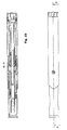
- Figs. 16 to 24 show an embodiment of the present invention.
- the embodiment comprises a further feature namely a dose setting means.
- This feature can be used to provide injectors for different medicaments and / or different doses depending on the type of disease and / or type of patient.
- the same injector can be used to deliver different doses independent of the design of the injector.
- the first example had a design that enabled a certain dose quantity, which was dependent on the actual design or stroke of the injector, which in turn means that if you would like to use the injector for a different dose quantity, the design, and thus the plastic moulding forms, had to be changed.
- the previous design is perfectly usable when the medicament always is to be delivered in a certain quantity.
- the dose setting function comprises a second generally tubular member 202 arranged between the dose setting knob 112 and the first tubular member 126, Fig. 16 .
- the tubular member 202 is rotationally locked to the dose setting knob by outwardly extending, oppositely arranged claws 203, Fig. 18 , between which corresponding inwardly extending claws on the dose setting knob fit.
- the plunger is held in an initial position by a set of oppositely arranged outwardly extending stop members 206, Fig. 21 on the plunger 128 abutting a first series of ledges 204 arranged on the inner surface of the dose setting knob 112.
- the ledges are designed in the same manner as for the first embodiment.
- the turning of the knob, Fig. 23 after attaching a needle at the front end of the injector, to a start position for priming, causes the stop members to slide off the ledges.
- the force of the plunger spring pushes the plunger forward, expelling any prevailing air in the cartridge.
- the movement is stopped when the outwardly extending knobs 130 of the plunger abut a second set of ledges 149 as for the first example, arranged on the inner surface of the first tubular member 126.
- the dose setting knob is now free to be turned to set a certain dose, Fig. 20 .
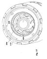
- the inner surface of the tubular member 202 is arranged with a series of ledges 208, Fig. 17 , at certain distances from the upper end of the injector, forming a set of descending ledges.
- Each ledge corresponds to a certain dose to be delivered.
- the turning of the knob is indicated by appropriate symbols or signs to tell the user which dose is set.
- the distance x corresponds to the length of the plunger to travel during injection, and thus corresponding to the delivered dose.
- the device is now ready for injection. When pressing the device against the injection site and penetrating the skin, Fig.
- the guide knobs of the needle shield link rotate the first tubular member as for the first embodiment, whereby the outwardly extending knobs of the plunger slip off the second set of ledges 149. This causes the plunger to move forward causing an injection until the outwardly extending stop members 206 abut one of the descending ledges 208 that is set for a certain dose, Fig. 22 .
- Figs. 25 and 26 show a variant 202' of the tubular member 202 in connection with the first tubular member 126.
- This variant is intended to be placed between the first tubular member 126 and the end wall 143 of the holder, rather than between the dose setting knob and the first tubular member.
- the first tubular member is arranged with a second stop ledge 149 onto which the knob 130 of the plunger rest after priming.
- the knob is pushed off the ledge 149 and runs down a groove 210 due to the force of the injection spring and thereby the forward movement of the plunger, causing an injection.
- the injection is stopped when the knob hits one of the dose ledges 208 of the tubular member 202'.
- Fig. 26 show how the tubular member 202' is attached to the dose setting knob with this arrangement having the first tubular member between them.
- the movement of the plunger from the locked delivery position to the position defined by the first stop ledge is the end of priming, i.e. deareating the syringe 136.
- this movement includes a mixing step, i.e. the plunger moves a stopper inside the cartridge to a position where two substances contained in the cartridge, and initially held separated from each other by the stopper, are mixed.
- a subsequent attachment of a needle causes a priming of the mixed cartridge, due to the pressure from the plunger on the mixed solution, whereby the plunger can move forward to the stop ledge and be ready for an injection.
- the travel of the plunger for mixing usually has to be longer than for a mere priming, but this design difference is easily feasible within the injector concept.
- the needle shield has been held in a retracted position inside the housing until activated. It is of course conceivable that the needle shield is in an extended position from the beginning and is only in a retracted position inside the housing during the penetration and injection steps. Further, even though a cartridge is described in the description of embodiments, other types of medicament containing enclosures may be used, such as ampoules, containers, etc.
Landscapes
- Health & Medical Sciences (AREA)
- Engineering & Computer Science (AREA)
- Life Sciences & Earth Sciences (AREA)
- Animal Behavior & Ethology (AREA)
- Public Health (AREA)
- Heart & Thoracic Surgery (AREA)
- Hematology (AREA)
- Anesthesiology (AREA)
- Veterinary Medicine (AREA)
- General Health & Medical Sciences (AREA)
- Biomedical Technology (AREA)
- Vascular Medicine (AREA)
- Environmental & Geological Engineering (AREA)
- Biophysics (AREA)
- Bioinformatics & Cheminformatics (AREA)
- Pulmonology (AREA)
- Infusion, Injection, And Reservoir Apparatuses (AREA)
Description
- The present invention relates to delivery devices such as injectors, mouth or nasal inhalers, powder or aerosol inhalers, nebulizers and the like.
- There are on the market a number of different delivery devices with varying degrees of automatic functions. The general trend is also that patients should be able to administer drugs and medicament by themselves, ie. without the need for trained staff to administer the drugs.
- There are however a number of aspects regarding delivery devices that are to be used by non-trained persons both in view of safety, both for the user and others that may come in contact with the device, as well as in view of handling and operation.
- For safety reasons many devices have been arranged with cover or protection means that are manually or automatically activated in order to protect persons from for example an injection needle, in particular after use.
- Many devices are provided with enclosures such as cartridges, 25 ampoules or syringes containing medicament in liquid form. When filling these containers with liquid a small amount of air is very often entrapped in the container, which air has to be removed before delivery. Some devices are of multi-chamber type where one component is powder and the other is liquid or two liquids or more liquids and powder chambers.
- For some types of medicament enclosures and treatment schemes there is a need to deliver a precise dose, which may be less than the total amount in the enclosure. For some types of medicament the dose to be delivered is so small that it is not practically possible to provide such a small compartment in the enclosure or to provide a device that is capable of expelling the content from such a small compartment.
- The above mentioned functions have been realised in a number of delivery devices with a varying degree of complexity.
-
WO2004/028598 relates to an injection device comprising a first and a second tubular member and a plunger that is arranged with a number of outwardly extending stop members. The device is activated by pressing the device/needle shield against and injection site to trigger the activation mechanism. The device does not disclose a dosing mechanism. - European patent application No.
298 067 -
EP 298 067 - Regarding needle covers that protect the needle after use, there are many documents disclosing this feature, eg.
US 5,658,259 andEP 298 067 - There is thus a need for a device that is easy to handle, fulfils the safety requirements that are requested for these types of devices and is uncomplicated and can be manufactured at a reduced cost.
- The aim of the present invention is to provide an injection device that is easy and safe to handle, based on a method for designing various features and various combinations.
- This aim is fulfilled with injection device according to
claim 1. Further advantageous features of the present invention are the object of the dependent claims. - According to a main aspect of the invention it is characterised by a device for controlling and performing functions of a device for delivery of medicament, comprising a number of components arranged to co-act with each other, comprising co-operating means, at least some of them arranged on the surfaces of the components, comprising guide means capable of guiding the relative movement between two co-acting components for controlling and performing at least one function.
- According to a further aspect of the invention the guide means comprises mechanical members like ridges, ledges or groove having side surfaces arranged on one component, against which protrusions, ridges, ledges or grooves on another component are in contact for guiding the relative movement.
- According to yet an aspect of the invention the co-operating means further comprises locking means capable of locking the co-acting components relative each other at pre-defined mutual positions.
- According to another aspect of the invention the locking means comprises grooves, cut-outs, recesses protrusions on one component, co-operating with protrusions, ridges, ledges or recesses on another component for locking the movement between the co-acting components.
- According to a further aspect of the invention the co-operating means comprises holding means, capable of holding two co-acting components in mutual positions in a first direction until one or more of other components are moved a certain amount in a direction deviating from said first direction, wherein the co-acting components are released from each other.
- Further the holding means comprises ledges, ridges, recesses on one component, co-acting with protrusions, ledges ridges or recesses on another component.
- Preferably at least one component is arranged as a generally tubular member, the inner and / or outer surfaces of which are arranged with said co-operating means.
- With the principle of the invention there are a number of advantages that are obtained. By utilizing co-operating means on at least two, preferably more, co-acting components for guiding their relative movement, the interaction between the components can be simplified, especially in view of designing and manufacturing the device and still have a reliable function. Further the co-operating means can be formed as locking members capable of locking the co-acting components. Further the co-operating means can be designed to hold the components in pre-defined positions relative each other.
- The co-operating means are preferably mechanical members in the form of grooves, ledger ridges, recesses, cut-outs, protrusions, threads and the like that are designed to guide, lock and / or hold the co-acting components in their movement relative each other.
- For certain types of applications such as injectors having a generally tubular form, at least one of the components is preferably tubular, having co-operating means arranged on its surfaces, which could be inner, outer and edge surfaces. The possibilities with the principle according to the invention are numerous since the number of surfaces that are available and the types and design of co-operating means possible are vast, almost all types of movements and functions are feasible, with a reduced number of components for the device compared to the state of the art. This could be achieved without reducing the overall functionality of the device. Rather on the contrary, since fewer components generally are needed for performing a number of functions, the interplay between components, and thus the dependency that each component in a chain or series is designed so that the desired function is obtained, is reduced.
- In all a device with a freedom to design and create a high degree of robust functionality is obtained with a reduced number of components, whereby the manufacturing costs are kept at a low level, which in turn enables the device to be used for example in a single dose delivery device that is discarded after completed injection.
- These and other aspects of and advantages with the present invention will become apparent from the following detailed description and the accompanying drawings.
- In the detailed description, reference will be made to the accompanying drawings, of which
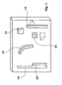
- Fig. 1
- is a schematic view of the general principle of the present invention,
- Fig.2
- is a variant of the general principle including a cylindrical component, a rotator,
- Figs. 3-6
- show further variants of the general principle,
- Fig. 7
- is a side view of a first embodiment of an injector comprising the present invention,
- Fig.8
- is a cross-sectional view of the injector according to
Fig. 7 , - Fig.9
- is a perspective view of the injector according to
Fig. 7 with the main tubular housing removed for simplicity, - Fig.10
- is a detailed view of a part of the injector of
Fig. 9 , - Fig. 11
- is a detailed view of a dose activating means displaying first stop means,
- Fig. 12
- is a view corresponding to
Fig. 9 during operation of the device, - Fig. 13 - 15
- are cross-sectional views according to
Fig. 8 during operation of the device, - Fig. 16 - 26
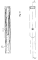
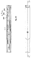
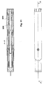
- are cross-sectional views of a further embodiment of the present invention in different modes of operation,
- Fig.20
- is an exploded view of the embodiment according to
Figs. 14-19 , and - Fig. 21
- is a variant of a component comprised in the second embodiment.
- The general aspect of the invention will first be described in connection to the drawings,
Figs. 1-6 . - The novel feature of the invention is the manner of controlling different functions of a device such as an injecting device. Depending on the degree of automation, such devices may have several functions included, which functions are more or less automated and may be working in series or in parallel with each other.
- These functions may include priming of the medicament in liquid form prior to injection, mixing of medicament for multi-compartment ampoules or syringes, penetration of a needle into the body of a patient, injection of the medicament in the body of the patient, withdrawal of needle after injection, advancing of a needle shield for protection of the needle and subsequent locking of the needle shield. Further features may include setting of specific doses, delivery of specific doses, etc. The different features and functions entail co-operation and / co-action between different components of the device such as pistons, sleeves, springs, locking hooks, threaded parts and the like.
- According to the present invention many or all of the above features and functions may be performed and controlled by co-operating means arranged on co-acting components of the device for enabling these functions. The co-operating means comprise mechanical members like
cams 10,ridges 12,protrusions 14, recesses 16, slots andgrooves 18,ledges 20,Fig. 1 ,threads 21,Fig. 3a , and the like, arranged on one or several surfaces of these components. These mechanical members arranged on one component co-operate withmechanical members 22 on another component, which components are arranged to co-act with each other in order to perform a certain function,Fig 2 . The cooperating means could be used to guide a movement between two co-acting components, like is shown inFig. 4a . First thegroove 18 only allows movement in one direction, 24, until a protrusion or pin 26 of the other component has moved from an initial position 261 to a certain position 262. The protrusion may be flexible and the groove may be arranged with aramp 28, whereby, when the protrusion has passed the ramp, it cannot move back to the initial position. The groove now allows a movement in the direction of thearrow 30 until the protrusion has moved to a position 263 when it is allowed to again move in the direction parallel to thefirst direction 24 to a position 264. - Not only can the co-operating means be arranged on a surface, but it is also possible to arrange them on
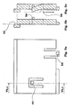
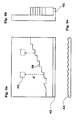
edge parts 32,Figs. 3a - c of the co-acting components. They can be formed as slots that have eitherstraight walls 34 or rampedwalls 36 in relation to the direction of the edge. They may further be arranged on one side only,Fig. 3c , or on both sides,Fig 3b , in the latter case if there are more than two co-operating components. The edge parts can be formed step-like 38 as shown inFig. 6a for providing certain defined distances d that amember 40 on another component is able to move, e.g. for delivering specific doses of medicament. - There could also be formed
ledges 42,Figs. 5 and6 , on the edges of one co-acting component co-operating with another component to form a mutual fixed relationship between the two,Fig. 6 a-c . The ledge can either be smooth or be ratchet-like 44 enabling movement in only one direction,Fig. 6c . - The mechanical members can then co-operate to move
components slidable movement 50,rotational movement 52 or combinations of these. The mechanical members can further co-operate to lock the components mutually in pre-defined positions after or before a function has been performed and / or hold the components in mutual positions until one or more of the components are moved a certain distance or rotated, after which they are released from each other and a certain function is performed of the device.Figs. 5a -- c show a few variants on movable,resilient locking members 54. The locking member shown inFig. 5b snaps into a groove or a recess when thepin 56 of the locking member is in a certain position. The locking member shown inFig. 5c locks into a groove or recess when the co-operating component has moved to a certain position where another component ormember 58 acts on the rear side of the locking member. This could then mean a temporary locking because when or if the other component is moved out of contact with the rear side of the locking member, it is moved out of the recess or groove.Fig. 3c shows another type ofmember 60 that is resiliently flexible in the direction of thearrow 62. When this member is moved to a certain position it comes in contact with aprotrusion 64 or the like whereby a frictional contact is obtained. This could be for temporarily holding the two co-acting components or to slow down the movement between the components. - Regarding injecting devices it is preferred that one central part containing these mechanical members is mainly cylindrical, 46,
Fig. 2 , since the injecting devices generally have this cylindrical "pen"-shape. Thiscylindrical part 46, hereafter named rotator, is arranged withmechanical members 12 on its surface, which could both the internal and external surface. The rotator could be arranged to be turnable 52 around its centre axis as well asslidable 50 along its centre axis. - The mechanical members of the rotator co-operate with other parts, 48, partly shown in
Fig. 2 , of the device, which parts are also arranged withmechanical members 22. As an example, the rotator may be arranged with an inclined ridge or guide, on which another mechanical member of another part is arranged to slide along. This sliding action may cause either the rotator or the other part, or both, to turn. The turning action may for example be to set a dose, to free a third part of the device arranged with a protrusion that is held by a stop ledge that has a certain extension, whereby the turning action causes the protrusion to move past the stop ledge. As an example, the protrusion may be arranged on apart of the device that acts on the syringe or ampoule containing medicament, such as a spring-loaded plunger, and when the protrusion has been moved past the stop ledge, which movement may have been caused by the needle shield pushed into the device, the plunger is free to act on the content of the syringe and thus to inject a dose of medicament. - The rotator or other parts of the device may further be arranged with recesses positioned on its surfaces, into which protrusions or the like will be positioned depending on the movement between the parts. As an example, a protrusion arranged on the needle shield may be moved, as the needle shield is extended to cover the needle after injection, into a recess, after which the needle shield is locked from movement.
- As can be understood by the above mentioned examples, there are numerous combinations that are possible within the described invention. There is thus the possibility to have guided longitudinal movements, inclined movements, rotational movements, and combinations of these with the co-operating means according to the invention as well as locking of components either temporarily or fixed. There are also numerous possibilities of using and designing different surfaces of the co-acting components in order to obtain the desired function and interaction.
- The principle according to the present invention may be used in a number of delivery devices such as injectors, mouth of nasal inhalers of powder or aerosol type, nebulizers, and the like where a number of functions are to be performed in order to deliver a dose.
- A first example, not forming part of the claimed invention, utilizing this principle is shown in the drawings 7--15. An injecting device comprises a generally tubular
main body 110, anactivation knob 112 and aneedle shield 114,Fig. 7 . - The
needle shield 114 is arranged slidably inside the main housing and is connected to aneedle shield link 116,Figs. 8 and9 . For clarity the main body is removed inFig. 9 . The needle shield link is arranged with an upper (to the right inFig. 9 )tubular part 118 and two longitudinally extendingarms 120. The end of the arms are arranged with outwardly extendingledges 122, which fit into recesses orpassages 124 in the upper part of the needle shield, thus obtaining the connection between the needle shield and the needle shield link. - Inside the needle shield link a generally first
tubular member 126 is rotationally and slidably arranged. It is arranged with a number of ridges and protrusions on its outer surface which are to cooperate with guide members arranged on the inner surface of the needle shield link, the function of which will be explained below. The upper end surface of the first tubular member is in contact with the lower end surface of theactivation knob 112, preventing longitudinal movement but allowing rotational movement between them. Inside the first tubular member, aplunger 128 is slidably arranged and movable with the help of an injection spring. The upper part of the plunger is arranged with a number of outwardly extendingstop members 130, arranged to cooperate with inwardly extendingstop members 132 on the inner surface of the activation knob, as will be explained below. The front end of the plunger is in contact with astopper 134 arranged inside acartridge 136 containing the medicament to be delivered to a patient. The cartridge is housed in aholder 138. The cartridge is held in the holder by anend piece 139 snap-fitted with holder. The lower end surface of the first tubular member is in contact with anend wall 143 of the holder. The holder is guided by the needle shield viagrooves 141,Fig. 13 . - A needle shield spring (not shown) is arranged to press on the needle shield link between a ledge on the housing and a ledge on the upper part of the needle shield link.
- The device is intended to function as follows. When the device is assembled and delivered to the user the needle shield is in a retracted position inside the main housing,
Fig. 8 , and held in this position against the force of the needle shield spring by an outwardly extendingknob 140 on theactivation knob 112 abutting an inwardly extendingknob 142 on the inner surface of theneedle shield link 116,Fig. 11 . - The
plunger 128 is in its rearmost position and the injection spring is tensioned. The plunger is held in this position by a set of oppositely arranged outwardly extendingknobs 130,Fig. 10 , on theplunger 128 abutting a first set ofledges 132 arranged on the inner surface of theactivation knob 112. Theledges 132 are arranged with longitudinally extendingprotrusions 148 for admitting movement between theknobs 130 and theledges 132 in only one direction. - When the patient is to use the device a new needle is attached to the lower, front, part of the cartridge by conventional means, such as screw threads or the like. Because the needle shield is in the retracted position, the cartridge end is easily accessible during attachment of the needle.
- Thereafter the device is to be primed. The activation knob is then turned from the locked position to a start position,
Fig. 13 , which may be indicated on the main housing adjacent the activation knob. The turning of the knob causes the outwardly extendingknobs 130 of theplunger 128 to slide off theledges 132 of the activation knob, whereby the force of the injection spring pushes the plunger towards the cartridge and thus moves the stopper inside the cartridge, thereby pressing any prevailing air and some liquid out of the cartridge through the needle. The movement is stopped when the outwardly extendingknobs 130 of the plunger abut a second set of ledges, 149,Fig. 14 , arranged on the inner surface of the upper part of the first tubular member. - The turning of the activation knob also causes the outwardly extending
knob 140 of the activation knob to be moved out of contact with the inwardly extendingknob 142 of theneedle shield link 116. The force of the needle shield spring then urges the needle shield and the needle shield link to an extended position, thereby covering the needle from sight,Fig. 13 . The inner surface of the shield link is arranged with guide knobs, which during the movement to an extended position run along aguide surface 150,Fig. 12 , having an inclination in relation to the longitudinal direction of the device. This causes the first tubular member to turn somewhat in relation to the needle shield link. - The device is now ready for injection. The needle shield is pressed against the injection site and the needle penetrates the skin. During the inward movement of the needle shield the guide knobs of the needle shield link run along longitudinally extending
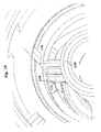
ridges 152,Fig. 12 until they come in contact withinclined ledges 154. The contact between these causes the first tubular member to turn during further movement of the needle shield and the needle shield link. The first tubular member is thus turned until the outwardly extendingknobs 130 of the plunger slip off the second set of ledges-arranged on the upper part of the first tubular member, thereby starting the injection. The plunger moves downward due to the force of the injection spring and theknobs 130 run in longitudinal grooves on the inner surface of the first tubular member. The movement of the plunger moves the stopper, whereby medicament is expelled through the needle, until the outwardly extendingknobs 130 of the plunger abut thewall 143,Fig. 14 . - When the injection is finished, the user removes the device from the injection site, whereby the needle shield and the needle shield link moves into an extended position. The guide knobs of the needle shield link now move along the other side of the
ridges 152 and at a certain position along this path, when the needle shield is in its most extended position covering the needle, the guide knobs fit into recesses in the first tubular member, thereby locking the needle shield in the extended position, preventing the needle shield to be pushed in again,Fig. 15 . The risk of unintentional needle sticks is thus eliminated. -
Figs. 16 to 24 show an embodiment of the present invention. The embodiment comprises a further feature namely a dose setting means. This feature can be used to provide injectors for different medicaments and / or different doses depending on the type of disease and / or type of patient. With the feature, the same injector can be used to deliver different doses independent of the design of the injector. The first example had a design that enabled a certain dose quantity, which was dependent on the actual design or stroke of the injector, which in turn means that if you would like to use the injector for a different dose quantity, the design, and thus the plastic moulding forms, had to be changed. The previous design is perfectly usable when the medicament always is to be delivered in a certain quantity. - As mentioned a main difference between the first example and the first embodiment is the dose setting function. It comprises a second generally tubular
member 202 arranged between thedose setting knob 112 and the firsttubular member 126,Fig. 16 . Thetubular member 202 is rotationally locked to the dose setting knob by outwardly extending, oppositely arrangedclaws 203,Fig. 18 , between which corresponding inwardly extending claws on the dose setting knob fit. As with the first example, the plunger is held in an initial position by a set of oppositely arranged outwardly extendingstop members 206,Fig. 21 on theplunger 128 abutting a first series ofledges 204 arranged on the inner surface of thedose setting knob 112. The ledges are designed in the same manner as for the first embodiment. The turning of the knob,Fig. 23 , after attaching a needle at the front end of the injector, to a start position for priming, causes the stop members to slide off the ledges. The force of the plunger spring pushes the plunger forward, expelling any prevailing air in the cartridge. The movement is stopped when the outwardly extendingknobs 130 of the plunger abut a second set ofledges 149 as for the first example, arranged on the inner surface of the firsttubular member 126. - The dose setting knob is now free to be turned to set a certain dose,
Fig. 20 . For this purpose the inner surface of thetubular member 202 is arranged with a series ofledges 208,Fig. 17 , at certain distances from the upper end of the injector, forming a set of descending ledges. Each ledge corresponds to a certain dose to be delivered. The turning of the knob is indicated by appropriate symbols or signs to tell the user which dose is set. As shown inFig. 20 , the distance x corresponds to the length of the plunger to travel during injection, and thus corresponding to the delivered dose. The device is now ready for injection. When pressing the device against the injection site and penetrating the skin,Fig. 21 and22 , the guide knobs of the needle shield link rotate the first tubular member as for the first embodiment, whereby the outwardly extending knobs of the plunger slip off the second set ofledges 149. This causes the plunger to move forward causing an injection until the outwardly extendingstop members 206 abut one of the descendingledges 208 that is set for a certain dose,Fig. 22 . - When the injection is finished the user removes the device and the same operation is performed by the device as for the first embodiment,
Fig. 23 . -
Figs. 25 and26 show a variant 202' of thetubular member 202 in connection with the firsttubular member 126. This variant is intended to be placed between the firsttubular member 126 and theend wall 143 of the holder, rather than between the dose setting knob and the first tubular member. The first tubular member is arranged with asecond stop ledge 149 onto which theknob 130 of the plunger rest after priming. When the first tubular member is turned due to that the needle shield is pushed in during penetration, as is described above, the knob is pushed off theledge 149 and runs down agroove 210 due to the force of the injection spring and thereby the forward movement of the plunger, causing an injection. The injection is stopped when the knob hits one of thedose ledges 208 of the tubular member 202'.Fig. 26 show how the tubular member 202' is attached to the dose setting knob with this arrangement having the first tubular member between them. - It is above described that the movement of the plunger from the locked delivery position to the position defined by the first stop ledge is the end of priming, i.e. deareating the
syringe 136. it may also be that, for dual chamber cartridges, this movement includes a mixing step, i.e. the plunger moves a stopper inside the cartridge to a position where two substances contained in the cartridge, and initially held separated from each other by the stopper, are mixed. A subsequent attachment of a needle causes a priming of the mixed cartridge, due to the pressure from the plunger on the mixed solution, whereby the plunger can move forward to the stop ledge and be ready for an injection. In this case the travel of the plunger for mixing usually has to be longer than for a mere priming, but this design difference is easily feasible within the injector concept. - In the embodiments shown, the needle shield has been held in a retracted position inside the housing until activated. It is of course conceivable that the needle shield is in an extended position from the beginning and is only in a retracted position inside the housing during the penetration and injection steps. Further, even though a cartridge is described in the description of embodiments, other types of medicament containing enclosures may be used, such as ampoules, containers, etc.
- It is to be understood that the above described and shown embodiment of the present invention is to be regarded as a non-limiting example and that it can be modified within the scope of the patent claims.
Claims (10)
- Injection device comprising:- a tubular elongated main body (110)- a needle shield (114) slidably arranged in said main body,- a needle shield link (116) slidably connected to said needle shield,- an enclosure containing medicament arranged in said main body,- a needle connected to said enclosure,- a plunger (128) operatively arranged to said enclosure for ejecting said medicament through said needle and arranged on its upper part with a first and a second set of outwardly extending stop members (130, 206),- spring means arranged with said plunger for operating said plunger,- a dose setting knob (112) arranged with inwardly extending stop members (204) on its inner surface which cooperate with the plunger's second set of outwardly extending stop members (206) for holding said plunger and said spring means in a tensioned locked position,- a needle shield spring surrounding the needle shield link (116),characterised in that:- said injection device further comprises a first tubular member (126) rotationally and slidably arranged inside said needle shield link (116),- said first tubular member comprises a number of ridges and protrusions on its outer surface and a second set of ledges (149) arranged on the inner surface,- said ridges and protrusions (150, 152, 154) on the outer surface of said first tubular member (126) cooperate with guide members arranged on the inner surface of said needle shield link (116),- said second set of ledges (149) on the inner surface of said first tubular member cooperate with the first set of outwardly extending stop members (130) of the plunger, wherein- said injection device further comprises a second tubular member (202) arranged inside said body, between the dose setting knob and the first tubular member (126), and rotationally locked to the dose setting knob (112) by outwardly extending, oppositely arranged claws (203), wherein said second tubular member is arranged with a set of descending ledges (208) on its inner surface, wherein said set of descending ledges cooperate with the plunger's second set of outwardly extending stop members (206) when the guide members of the needle shield link (116) rotate the first tubular member (126) thereby causing the plunger (128) to slip off the second set of ledges (149) causing the plunger (128) to move forward causing an injection until the second set of outwardly extending members (206) abut one of the descending ledges (208) which is set for a certain dose.
- Injection device according to claim 1, characterised in that said needle shield is arranged and designed to be in a retracted position inside the main body and to be held in this position against the force of the needle shield spring by an outwardly extending knob (140) on the dose setting knob's outer surface abutting an inwardly extending knob (142) on the inner surface of the needle shield link (116).
- Injection device according to claim 1, characterised in that said needle shield is arranged and designed to be in an extended position and held in this position by the force of the needle shield spring.
- Injection device according to claims 1-3, characterised in that the set of descending ledges (208) are arranged and designed to be positioned in line with the second set of outwardly extending stop members (206) of the plunger for permitting different lengths of movement of the plunger and thus different doses of the medicament.
- Injection device according to any of the preceding claims, characterised in that said dose setting knob (112) is turned from a locked position to an optional dose position, wherein the turning of said dose setting knob causes the outwardly extending stop members (206) of the plunger (128) to slide off the inwardly extending stop members (204) of the dose setting knob (112) until said outwardly extending stop members (130) of the plunger abut the second set of ledges (149) arranged on the inner surface of the first tubular member (126), whereby the force of the injection spring pushes the plunger towards the enclosure in order to move the stopper inside the enclosure and thereby pressing any prevailing air and some liquid out of the enclosure through the needle.
- Injection device according to claim 5, characterised in that the turning of the dose setting knob causes also the outwardly extending knob (140) on the dose setting knob (112) to be moved out of contact with the inwardly extending knob (142) of the needle shield link (116), and then the force of the needle shield spring urges the needle shield and the needle shield link to an extending position and thereby covering the needle from sight.
- Injection device according to any of the preceding claims, characterized in that the guide members of the needle shield link which during the movement to an extended position run along a guide surface (150) on the outer surface of the first tubular member (126), which tubular member (126) has extending ridges and inclined ledges in relation to the longitudinal direction of the device which ridges and inclined ledges thereby cause the first tubular member to rotate somewhat in relation to the needle shield link.
- Injection device according to any of the preceding claims, characterised in that during an inward movement of the needle shield (114), the guide members of the needle shield link (116) are arranged and designed to run along longitudinally extending ridges (152) on the outer surface of the first tubular member (126) until said guide members come in contact with the inclined ledges (154) on the outer surface of the first tubular member, whereby said contact between these causes the first tubular member to turn until the outwardly extending stop members (130) of the plunger slip off the second set of ledges (149) arranged on the upper part of the first tubular member and thereby moving the plunger downward due to the force of the injection spring and ejecting the medicament through the needle until said outwardly extending stop members (206) of the plunger abut one of the descending ledges (208).
- Injection device according to any of the preceding claims, characterised in that during an outward movement of the needle shield (114), the guide members of the needle shield link (116) move along the other side of the ridges (152) and at a certain position along this path, said guide members fit into recesses in the first tubular member, thereby locking the needle shield in an extended position.
- Injection device according to claim 8, characterized in that said guide members of the needle shield link pass, by depressing them, outwardly protruding acting snaps, thereby locking the needle shield in an extended position.
Priority Applications (4)
| Application Number | Priority Date | Filing Date | Title |
|---|---|---|---|
| DK11194506.9T DK2438948T3 (en) | 2004-11-24 | 2005-11-24 | A tubular rotor to a medicament injection device and the medicament injection device |
| EP15191042.9A EP3002019B1 (en) | 2004-11-24 | 2005-11-24 | Injection device |
| EP11194506.9A EP2438948B1 (en) | 2004-11-24 | 2005-11-24 | Tubular rotator for a medicament injection device, and medicament injection device |
| EP17195102.3A EP3308813A1 (en) | 2004-11-24 | 2005-11-24 | Injection device |
Applications Claiming Priority (3)
| Application Number | Priority Date | Filing Date | Title |
|---|---|---|---|
| US63019704P | 2004-11-24 | 2004-11-24 | |
| SE0502370 | 2005-10-25 | ||
| PCT/SE2005/001764 WO2006057604A1 (en) | 2004-11-24 | 2005-11-24 | Injection device |
Related Child Applications (4)
| Application Number | Title | Priority Date | Filing Date |
|---|---|---|---|
| EP17195102.3A Division EP3308813A1 (en) | 2004-11-24 | 2005-11-24 | Injection device |
| EP15191042.9A Division EP3002019B1 (en) | 2004-11-24 | 2005-11-24 | Injection device |
| EP11194506.9A Division-Into EP2438948B1 (en) | 2004-11-24 | 2005-11-24 | Tubular rotator for a medicament injection device, and medicament injection device |
| EP11194506.9A Division EP2438948B1 (en) | 2004-11-24 | 2005-11-24 | Tubular rotator for a medicament injection device, and medicament injection device |
Publications (3)
| Publication Number | Publication Date |
|---|---|
| EP1814615A1 EP1814615A1 (en) | 2007-08-08 |
| EP1814615A4 EP1814615A4 (en) | 2010-07-28 |
| EP1814615B1 true EP1814615B1 (en) | 2015-10-28 |
Family
ID=36498273
Family Applications (4)
| Application Number | Title | Priority Date | Filing Date |
|---|---|---|---|
| EP11194506.9A Expired - Lifetime EP2438948B1 (en) | 2004-11-24 | 2005-11-24 | Tubular rotator for a medicament injection device, and medicament injection device |
| EP17195102.3A Withdrawn EP3308813A1 (en) | 2004-11-24 | 2005-11-24 | Injection device |
| EP05808428.6A Expired - Lifetime EP1814615B1 (en) | 2004-11-24 | 2005-11-24 | Injection device |
| EP15191042.9A Expired - Lifetime EP3002019B1 (en) | 2004-11-24 | 2005-11-24 | Injection device |
Family Applications Before (2)
| Application Number | Title | Priority Date | Filing Date |
|---|---|---|---|
| EP11194506.9A Expired - Lifetime EP2438948B1 (en) | 2004-11-24 | 2005-11-24 | Tubular rotator for a medicament injection device, and medicament injection device |
| EP17195102.3A Withdrawn EP3308813A1 (en) | 2004-11-24 | 2005-11-24 | Injection device |
Family Applications After (1)
| Application Number | Title | Priority Date | Filing Date |
|---|---|---|---|
| EP15191042.9A Expired - Lifetime EP3002019B1 (en) | 2004-11-24 | 2005-11-24 | Injection device |
Country Status (8)
| Country | Link |
|---|---|
| US (5) | US7597685B2 (en) |
| EP (4) | EP2438948B1 (en) |
| CN (1) | CN101119761B (en) |
| AU (1) | AU2005310060B2 (en) |
| CA (1) | CA2587408C (en) |
| DK (1) | DK1814615T3 (en) |
| ES (1) | ES2557778T3 (en) |
| WO (1) | WO2006057604A1 (en) |
Families Citing this family (195)
| Publication number | Priority date | Publication date | Assignee | Title |
|---|---|---|---|---|
| ATE409057T1 (en) | 2002-02-11 | 2008-10-15 | Antares Pharma Inc | INTRADERMAL INJECTION DEVICE |
| US9486581B2 (en) | 2002-09-11 | 2016-11-08 | Becton, Dickinson And Company | Injector device with force lock-out and injection rate limiting mechanisms |
| CH696421A5 (en) | 2003-12-18 | 2007-06-15 | Tecpharma Licensing Ag | Autoinjector with arresting the drug container. |
| CN101119761B (en) * | 2004-11-24 | 2010-08-18 | Shl医药公司 | Injection device |
| WO2006079064A1 (en) | 2005-01-24 | 2006-07-27 | Antares Pharma, Inc. | Prefilled needle assisted jet injector |
| US8251947B2 (en) | 2006-05-03 | 2012-08-28 | Antares Pharma, Inc. | Two-stage reconstituting injector |
| WO2007131025A1 (en) | 2006-05-03 | 2007-11-15 | Antares Pharma, Inc. | Injector with adjustable dosing |
| US7993264B2 (en) | 2006-11-09 | 2011-08-09 | Ams Research Corporation | Orientation adapter for injection tube in flexible endoscope |
| DE102007016811A1 (en) | 2007-04-05 | 2008-10-09 | Tecpharma Licensing Ag | Device for administering a fluid substance from a multi-chamber ampoule |
| DE102007030327A1 (en) | 2007-06-29 | 2009-01-02 | Tecpharma Licensing Ag | Injection device with a spring for a needle protection sleeve |
| DK2170435T3 (en) | 2007-07-19 | 2018-02-12 | Shl Group Ab | AUTOMATIC DEVICE FOR THE DELIVERY OF A MEDICINE |
| DE102007034871A1 (en) * | 2007-07-24 | 2009-01-29 | Lts Lohmann Therapie-Systeme Ag | Disposable injector with manually operated piston |
| WO2009040602A1 (en) * | 2007-09-25 | 2009-04-02 | Becton Dickinson France | Autoinject0r with deactivating means moveable by a safety shield |
| US9173997B2 (en) | 2007-10-02 | 2015-11-03 | Medimop Medical Projects Ltd. | External drug pump |
| US7967795B1 (en) | 2010-01-19 | 2011-06-28 | Lamodel Ltd. | Cartridge interface assembly with driving plunger |
| US9345836B2 (en) | 2007-10-02 | 2016-05-24 | Medimop Medical Projects Ltd. | Disengagement resistant telescoping assembly and unidirectional method of assembly for such |
| US9656019B2 (en) | 2007-10-02 | 2017-05-23 | Medimop Medical Projects Ltd. | Apparatuses for securing components of a drug delivery system during transport and methods of using same |
| US10420880B2 (en) | 2007-10-02 | 2019-09-24 | West Pharma. Services IL, Ltd. | Key for securing components of a drug delivery system during assembly and/or transport and methods of using same |
| JP5731829B2 (en) | 2008-03-10 | 2015-06-10 | アンタレス・ファーマ・インコーポレーテッド | Syringe safety device |
| ES2615954T3 (en) | 2008-03-13 | 2017-06-08 | Becton, Dickinson And Company | Pen needle safety set with end protection for the patient and not for the patient |
| US8801673B2 (en) | 2008-03-13 | 2014-08-12 | Becton Dickinson & Company | Safety pen needle assembly having shield for non-patient end |
| CA2719110C (en) | 2008-03-13 | 2017-07-25 | Becton, Dickinson And Company | Safety needle assembly |
| AU2009246225B2 (en) | 2008-05-14 | 2012-07-19 | J&J Solutions, Inc. | Systems and methods for safe medicament transport |
| US8177749B2 (en) | 2008-05-20 | 2012-05-15 | Avant Medical Corp. | Cassette for a hidden injection needle |
| MX384690B (en) | 2008-05-20 | 2025-03-14 | Avant Medical Corp | AUTO-INJECTOR SYSTEM. |
| US8052645B2 (en) | 2008-07-23 | 2011-11-08 | Avant Medical Corp. | System and method for an injection using a syringe needle |
| EP3581224A1 (en) | 2008-08-05 | 2019-12-18 | Antares Pharma, Inc. | Multiple dosage injector |
| GB2463071A (en) * | 2008-09-02 | 2010-03-03 | Owen Mumford Ltd | Auto-injector syringe with safety shield |
| US9393369B2 (en) | 2008-09-15 | 2016-07-19 | Medimop Medical Projects Ltd. | Stabilized pen injector |
| US12097357B2 (en) | 2008-09-15 | 2024-09-24 | West Pharma. Services IL, Ltd. | Stabilized pen injector |
| WO2010033790A2 (en) * | 2008-09-18 | 2010-03-25 | Becton, Dickinson And Company | Medical injector with rotatable body portions |
| US20100145305A1 (en) * | 2008-11-10 | 2010-06-10 | Ruth Alon | Low volume accurate injector |
| AU2009322967B2 (en) | 2008-12-05 | 2015-06-11 | Ams Research Corporation | Devices, systems and methods for delivering fluid to tissue |
| EP2381980A2 (en) | 2008-12-05 | 2011-11-02 | AMS Research Corporation | Devices, systems, and related methods for delivery of fluid to tissue |
| EP2382000A2 (en) * | 2008-12-05 | 2011-11-02 | AMS Research Corporation | Devices, systems and methods for delivering fluid to tissue |
| EP2384209A2 (en) | 2008-12-16 | 2011-11-09 | AMS Research Corporation | Needleless injection device components, systems, and methods |
| US9295823B2 (en) | 2008-12-16 | 2016-03-29 | Robert L. Rykhus, Jr. | Needleless injection device components, systems, and methods |
| WO2010077271A2 (en) | 2008-12-29 | 2010-07-08 | Ams Research Corporation | Method and apparatus for compensating for injection media viscosity in a pressurized drug injection system |
| GB0900930D0 (en) * | 2009-01-20 | 2009-03-04 | Future Injection Technologies Ltd | Injection device |
| AU2010226442A1 (en) | 2009-03-20 | 2011-10-13 | Antares Pharma, Inc. | Hazardous agent injection system |
| TWI519330B (en) * | 2009-06-02 | 2016-02-01 | 賽諾菲阿凡提斯德意志有限公司 | Medicated module with user selection |
| US9138535B2 (en) | 2009-07-20 | 2015-09-22 | Ams Research Corporation | High pressure injection catheter systems |
| US8628494B2 (en) | 2009-07-20 | 2014-01-14 | Ams Research Corporation | Devices, systems, and methods for delivering fluid to tissue |
| WO2011011392A2 (en) | 2009-07-20 | 2011-01-27 | Ams Research Corporation | Needleless injection device components, systems, and methods |
| WO2011011423A1 (en) | 2009-07-20 | 2011-01-27 | Ams Research Corporation | Needleless injection device components, systems, and methods |
| JP5703299B2 (en) * | 2009-09-07 | 2015-04-15 | サノフィ−アベンティス・ドイチュラント・ゲゼルシャフト・ミット・ベシュレンクテル・ハフツング | Drive mechanism for drug delivery device |
| US10071198B2 (en) | 2012-11-02 | 2018-09-11 | West Pharma. Servicees IL, Ltd. | Adhesive structure for medical device |
| US8157769B2 (en) | 2009-09-15 | 2012-04-17 | Medimop Medical Projects Ltd. | Cartridge insertion assembly for drug delivery system |
| US10071196B2 (en) | 2012-05-15 | 2018-09-11 | West Pharma. Services IL, Ltd. | Method for selectively powering a battery-operated drug-delivery device and device therefor |
| JP5752693B2 (en) * | 2009-09-30 | 2015-07-22 | サノフィ−アベンティス・ドイチュラント・ゲゼルシャフト・ミット・ベシュレンクテル・ハフツング | Assembly and piston rod for a drug delivery device |
| CA2773013A1 (en) * | 2009-09-30 | 2011-04-07 | Sanofi-Aventis Deutschland Gmbh | Assembly for a drug delivery device |
| US8348898B2 (en) | 2010-01-19 | 2013-01-08 | Medimop Medical Projects Ltd. | Automatic needle for drug pump |
| EP2536452B1 (en) | 2010-02-18 | 2018-08-29 | Sanofi-Aventis Deutschland GmbH | Auto-injector |
| IT1398501B1 (en) * | 2010-03-10 | 2013-03-01 | Menarini Int Operations Lu Sa | AUTOINECTOR DEVICE FOR TWO DRUG DOSES |
| US20130126559A1 (en) * | 2010-04-30 | 2013-05-23 | Bayer Intellectual Property Gmbh | Displacement Syringe |
| WO2011141907A1 (en) | 2010-05-10 | 2011-11-17 | Medimop Medical Projects Ltd. | Low volume accurate injector |
| EP2399635A1 (en) | 2010-06-28 | 2011-12-28 | Sanofi-Aventis Deutschland GmbH | Auto-injector |
| PL2588168T3 (en) * | 2010-07-02 | 2015-08-31 | Sanofi Aventis Deutschland | Safety device for a pre-filled syringe and injection device |
| CN103328026B (en) | 2010-07-02 | 2015-05-13 | 卡勒贝控股有限公司,公司编号:681498 | Preservative-free follicle stimulating hormone solution delivery device |
| DK2640449T3 (en) * | 2010-11-18 | 2015-10-26 | Shl Group Ab | DRUG DELIVERY DEVICES |
| TWI476024B (en) * | 2010-11-18 | 2015-03-11 | Shl Group Ab | Medicament delivery device |
| WO2012072562A1 (en) | 2010-11-29 | 2012-06-07 | Sanofi-Aventis Deutschland Gmbh | Medicated module with automatic reservoir engagement |
| CA2818833A1 (en) * | 2010-11-29 | 2012-06-07 | Thomas Urs Thueer | Medicated module with automatic reservoir engagement |
| US8979797B2 (en) | 2010-12-16 | 2015-03-17 | Ams Research Corporation | High pressure delivery system and method for treating pelvic disorder using large molecule therapeutics |
| EP2468332A1 (en) * | 2010-12-21 | 2012-06-27 | Sanofi-Aventis Deutschland GmbH | Auto-injector |
| USRE48593E1 (en) | 2010-12-21 | 2021-06-15 | Sanofi-Aventis Deutschland Gmbh | Auto-injector |
| EP2468336A1 (en) | 2010-12-21 | 2012-06-27 | Sanofi-Aventis Deutschland GmbH | Auto-injector |
| EP2468333A1 (en) | 2010-12-21 | 2012-06-27 | Sanofi-Aventis Deutschland GmbH | Auto-injector |
| EP2468330A1 (en) | 2010-12-21 | 2012-06-27 | Sanofi-Aventis Deutschland GmbH | Auto-injector |
| US9220847B2 (en) * | 2011-01-11 | 2015-12-29 | Shl Group Ab | Medicament delivery device |
| MX336571B (en) | 2011-01-24 | 2016-01-25 | Elcam Medical Agricultural Cooperative Ass Ltd | INJECTOR. |
| EP2489389A1 (en) | 2011-02-18 | 2012-08-22 | Sanofi-Aventis Deutschland GmbH | Detent mechanism |
| EP2489385A1 (en) | 2011-02-18 | 2012-08-22 | Sanofi-Aventis Deutschland GmbH | Auto-injector |
| WO2012122643A1 (en) * | 2011-03-11 | 2012-09-20 | University Of Saskatchewan | Injection assist device and method |
| USD702834S1 (en) | 2011-03-22 | 2014-04-15 | Medimop Medical Projects Ltd. | Cartridge for use in injection device |
| CA3021845C (en) | 2011-04-20 | 2022-03-29 | Amgen Inc. | Autoinjector apparatus |
| EP2714156B1 (en) * | 2011-06-02 | 2018-07-11 | West Pharmaceutical Services, Inc. | Needle-protection device for a syringe |
| CN103732278B (en) * | 2011-06-17 | 2016-02-17 | 赛诺菲-安万特德国有限公司 | Cartridge holder assembly for drug delivery device |
| US8496619B2 (en) | 2011-07-15 | 2013-07-30 | Antares Pharma, Inc. | Injection device with cammed ram assembly |
| US9220660B2 (en) | 2011-07-15 | 2015-12-29 | Antares Pharma, Inc. | Liquid-transfer adapter beveled spike |
| CH705345A2 (en) * | 2011-08-04 | 2013-02-15 | Tecpharma Licensing Ag | Injector with needle protection device. |
| ITFI20110194A1 (en) | 2011-09-08 | 2013-03-09 | Menarini Int Operations Lu Sa | MEDICINE DOSES SELF-INJECTION DEVICE |
| EP2572741A1 (en) | 2011-09-23 | 2013-03-27 | Sanofi-Aventis Deutschland GmbH | Medicament delivery device and actuation mechanism for a drug delivery device |
| JP5847316B2 (en) * | 2011-09-27 | 2016-01-20 | エス・ホー・エル・グループ・アクチボラゲットShl Group Ab | Medical delivery device having an initial locked state, an intermediate starting ready state and a drug delivery state |
| EP2601992A1 (en) | 2011-12-08 | 2013-06-12 | Sanofi-Aventis Deutschland GmbH | Syringe carrier |
| US9827380B2 (en) * | 2011-12-15 | 2017-11-28 | Shl Group Ab | Cap assembly |
| EP2606924A1 (en) | 2011-12-21 | 2013-06-26 | Sanofi-Aventis Deutschland GmbH | Autoinjector having a retracting syringe carrier |
| PT2822618T (en) | 2012-03-06 | 2024-03-04 | Antares Pharma Inc | Prefilled syringe with breakaway force feature |
| WO2013134465A1 (en) * | 2012-03-07 | 2013-09-12 | West Pharmaceutical Services, Inc. | Low radial profile needle safety device |
| US10004854B2 (en) | 2012-03-07 | 2018-06-26 | West Pharmaceutical Services, Inc. | Low radial profile needle safety device |
| US9072827B2 (en) | 2012-03-26 | 2015-07-07 | Medimop Medical Projects Ltd. | Fail safe point protector for needle safety flap |
| EP2833944A4 (en) | 2012-04-06 | 2016-05-25 | Antares Pharma Inc | NEEDLE ASSISTED JET INJECTION ADMINISTRATION OF TESTOSTERONE COMPOSITIONS |
| USD808010S1 (en) | 2012-04-20 | 2018-01-16 | Amgen Inc. | Injection device |
| USD898908S1 (en) | 2012-04-20 | 2020-10-13 | Amgen Inc. | Pharmaceutical product cassette for an injection device |
| US9364610B2 (en) | 2012-05-07 | 2016-06-14 | Antares Pharma, Inc. | Injection device with cammed ram assembly |
| WO2014001319A1 (en) * | 2012-06-29 | 2014-01-03 | Novo Nordisk A/S | Spring driven injection device |
| EP2719414A1 (en) | 2012-10-15 | 2014-04-16 | Sanofi-Aventis Deutschland GmbH | Medicament delivery device with use indicator |
| WO2014095424A1 (en) * | 2012-12-21 | 2014-06-26 | Carebay Europe Ltd | Medicament delivery device |
| US9421323B2 (en) | 2013-01-03 | 2016-08-23 | Medimop Medical Projects Ltd. | Door and doorstop for portable one use drug delivery apparatus |
| PT2953667T (en) * | 2013-02-11 | 2020-01-28 | Antares Pharma Inc | NEEDLE-ASSISTED JET INJECTION DEVICE WITH REDUCED TRIGGER STRENGTH |
| JP6030803B2 (en) | 2013-03-11 | 2016-11-24 | アンタレス・ファーマ・インコーポレーテッド | Dose syringe with pinion system |
| WO2014165136A1 (en) | 2013-03-12 | 2014-10-09 | Antares Pharma, Inc. | Constant volume prefilled syringes and kits thereof |
| EP2777684A1 (en) | 2013-03-14 | 2014-09-17 | Sanofi-Aventis Deutschland GmbH | Medicament container carrier and adapter |
| TWI580451B (en) | 2013-03-15 | 2017-05-01 | 安美基公司 | Cassette for an injector and method of using an autoinjector apparatus having an autoinjector and a cassette |
| EP2968775B1 (en) | 2013-03-15 | 2019-12-18 | Amgen Inc. | Drug cassette, autoinjector, and autoinjector system |
| EP3590568A1 (en) | 2013-03-22 | 2020-01-08 | TecPharma Licensing AG | Substance dispensing device with a signalling device |
| DE102013007389A1 (en) * | 2013-04-30 | 2014-10-30 | Britannia Pharmaceuticals Ltd. | Drug delivery device |
| US9011164B2 (en) | 2013-04-30 | 2015-04-21 | Medimop Medical Projects Ltd. | Clip contact for easy installation of printed circuit board PCB |
| EP2823841A1 (en) | 2013-07-09 | 2015-01-14 | Sanofi-Aventis Deutschland GmbH | Autoinjector |
| EP2823836A1 (en) | 2013-07-09 | 2015-01-14 | Sanofi-Aventis Deutschland GmbH | Autoinjector |
| EP2823838A1 (en) | 2013-07-09 | 2015-01-14 | Sanofi-Aventis Deutschland GmbH | Autoinjector |
| EP3035980A1 (en) | 2013-08-19 | 2016-06-29 | Dr. Reddy's Laboratories Ltd. | Selectable single dose auto-injector and methods of making and using same |
| ES2598061T3 (en) | 2013-12-10 | 2017-01-25 | Becton, Dickinson And Company | Passive safety set of the pen syringe needle |
| US9649452B2 (en) | 2013-12-10 | 2017-05-16 | Becton, Dickinson And Company | Active safety pen needle assembly |
| GB201402423D0 (en) * | 2014-02-12 | 2014-03-26 | New Injection Systems Ltd | Auto-injector assembly |
| TWI616218B (en) * | 2014-03-06 | 2018-03-01 | 卡貝歐洲有限公司 | Device for delivering drugs |
| EP2923714A1 (en) | 2014-03-28 | 2015-09-30 | Sanofi-Aventis Deutschland GmbH | Autoinjector triggered by skin contact |
| EP3139976B1 (en) | 2014-05-06 | 2019-06-12 | SHL Medical AG | Medicament delivery device with rotator retaining the plunger rod |
| EP3154611B1 (en) * | 2014-06-10 | 2020-07-08 | SHL Medical AG | Plunger segments drive mechanism for a medicament delivery device |
| CH707898A2 (en) * | 2014-07-29 | 2014-10-15 | Tecpharma Licensing Ag | Autoinjector with adjustable dose. |
| AU2015372441A1 (en) | 2014-12-23 | 2017-08-10 | Automed Pty Ltd | Delivery apparatus, system and associated methods |
| US10293120B2 (en) | 2015-04-10 | 2019-05-21 | West Pharma. Services IL, Ltd. | Redundant injection device status indication |
| US10149943B2 (en) | 2015-05-29 | 2018-12-11 | West Pharma. Services IL, Ltd. | Linear rotation stabilizer for a telescoping syringe stopper driverdriving assembly |
| TW201707737A (en) | 2015-06-03 | 2017-03-01 | 賽諾菲阿凡提斯德意志有限公司 | Drug delivery device (1) |
| TW201700118A (en) | 2015-06-03 | 2017-01-01 | 賽諾菲阿凡提斯德意志有限公司 | Drug delivery device (3) |
| TW201707738A (en) | 2015-06-03 | 2017-03-01 | 賽諾菲阿凡提斯德意志有限公司 | Syringe holder and autoinjector (2) |
| TW201700117A (en) | 2015-06-03 | 2017-01-01 | 賽諾菲阿凡提斯德意志有限公司 | Syringe bracket and assembly method for autoinjector |
| TW201705994A (en) | 2015-06-03 | 2017-02-16 | 賽諾菲阿凡提斯德意志有限公司 | Automatic syringe and assembly method |
| EP3302652B1 (en) | 2015-06-04 | 2023-09-06 | Medimop Medical Projects Ltd. | Cartridge insertion for drug delivery device |
| AU2016311047B2 (en) * | 2015-08-25 | 2020-12-10 | Novo Nordisk A/S | A medical injection device with a cleaning chamber |
| WO2017049107A1 (en) | 2015-09-17 | 2017-03-23 | J&J SOLUTIONS, INC. d/b/a Corvida Medical | Medicament vial assembly |
| US10576207B2 (en) | 2015-10-09 | 2020-03-03 | West Pharma. Services IL, Ltd. | Angled syringe patch injector |
| US9987432B2 (en) | 2015-09-22 | 2018-06-05 | West Pharma. Services IL, Ltd. | Rotation resistant friction adapter for plunger driver of drug delivery device |
| JP7017512B2 (en) | 2015-10-09 | 2022-02-08 | ウェスト ファーマ サービシーズ イスラエル リミテッド | Bending fluid path type accessories for filled fluid containers |
| EP3362114B1 (en) | 2015-10-13 | 2024-03-27 | Cormed Ltd | Automated compounding equipment for closed fluid transfer system |
| EP3711793B1 (en) | 2016-01-21 | 2021-12-01 | West Pharma Services IL, Ltd. | A method of connecting a cartridge to an automatic injector |
| JP6542481B2 (en) | 2016-01-21 | 2019-07-10 | ウェスト ファーマ サービシーズ イスラエル リミテッド | system |
| US11311674B2 (en) | 2016-01-21 | 2022-04-26 | West Pharma. Services IL, Ltd. | Medicament delivery device comprising a visual indicator |
| CH710381A2 (en) * | 2016-02-25 | 2016-05-13 | Tecpharma Licensing Ag | Injection device for up-dosing and the distribution of a dose of a fluid product. |
| US11389597B2 (en) | 2016-03-16 | 2022-07-19 | West Pharma. Services IL, Ltd. | Staged telescopic screw assembly having different visual indicators |
| USD819198S1 (en) | 2016-04-28 | 2018-05-29 | Amgen Inc. | Autoinjector with removable cap |
| EP3463526B1 (en) | 2016-06-02 | 2024-08-21 | West Pharma. Services Il, Ltd. | Three position needle retraction |
| CN109196569A (en) * | 2016-06-08 | 2019-01-11 | 艾斯曲尔医疗公司 | Drug administration mechanism for medicament conveying training device |
| EP3490643B1 (en) | 2016-08-01 | 2021-10-27 | West Pharma. Services Il, Ltd. | Anti-rotation cartridge pin |
| EP3978047B1 (en) | 2016-08-01 | 2023-08-23 | West Pharma Services IL, Ltd | Partial door closure prevention spring |
| HUE063135T2 (en) | 2016-09-23 | 2023-12-28 | Hoffmann La Roche | Uses of il-13 antagonists for treating atopic dermatitis |
| EP3595750B1 (en) | 2017-03-15 | 2021-08-11 | Owen Mumford Limited | An injection apparatus |
| GB2560557A (en) | 2017-03-15 | 2018-09-19 | Owen Mumford Ltd | Injection Device |
| EP3630226B1 (en) | 2017-05-30 | 2025-10-22 | West Pharma. Services Il, Ltd. | Modular drive train for wearable injector |
| EP4585240A3 (en) * | 2017-11-03 | 2025-09-10 | Sanofi | Drug delivery device |
| CN114470420B (en) | 2017-12-22 | 2024-08-27 | 西氏医药包装(以色列)有限公司 | Syringes for different sized cartridges |
| CN108066851B (en) * | 2017-12-28 | 2024-11-19 | 江苏万海医疗器械有限公司 | Injection device |
| WO2019175665A2 (en) | 2018-03-13 | 2019-09-19 | Mylan Uk Healthcare Ltd. | Devices for injecting medicaments and methods of use |
| JP7464535B2 (en) * | 2018-05-24 | 2024-04-09 | ノバルティス アーゲー | Automated Drug Delivery Device |
| US10532049B1 (en) | 2018-08-27 | 2020-01-14 | Pharmaceutical Industries Limited | Parenteral unit dosage form of dihydroergotamine |
| GB2577537A (en) * | 2018-09-28 | 2020-04-01 | Owen Mumford Ltd | Injection device fill volume management |
| GB2577538B (en) * | 2018-09-28 | 2021-10-13 | Owen Mumford Ltd | Injection device fill volume management |
| KR102956779B1 (en) * | 2019-01-14 | 2026-04-27 | 필립모리스 프로덕츠 에스.에이. | Cartridges, inhaler devices, and kits for dry powder delivery |
| MX2022003700A (en) | 2019-09-30 | 2022-04-26 | Amgen Inc | DRUG ADMINISTRATION DEVICE. |
| USD1010811S1 (en) | 2019-09-30 | 2024-01-09 | Amgen Inc. | Handheld drug delivery device |
| CN118576828A (en) | 2019-09-30 | 2024-09-03 | 美国安进公司 | Drug delivery devices |
| CN114423475B (en) | 2019-09-30 | 2024-03-26 | 美国安进公司 | Drug delivery device and method for delivering a drug |
| CN114450048B (en) | 2019-09-30 | 2025-02-18 | 美国安进公司 | Drug delivery devices |
| AU2020357201B2 (en) | 2019-09-30 | 2025-11-27 | Amgen Inc. | Drug delivery device |
| KR102823691B1 (en) | 2019-12-11 | 2025-06-24 | 에스에이치엘 메디컬 아게 | drug delivery device |
| USD1030040S1 (en) | 2020-01-14 | 2024-06-04 | Amgen Inc. | Handheld drug delivery device |
| USD1030041S1 (en) | 2020-01-14 | 2024-06-04 | Amgen Inc. | Handheld drug delivery device |
| US11957542B2 (en) | 2020-04-30 | 2024-04-16 | Automed Patent Holdco, Llc | Sensing complete injection for animal injection device |
| USD974547S1 (en) | 2020-11-05 | 2023-01-03 | Amgen Inc. | Handheld drug delivery device |
| JP2021500644S (en) | 2020-11-05 | 2022-12-27 | Syringe | |
| USD973866S1 (en) | 2020-11-05 | 2022-12-27 | Amgen Inc. | Handheld drug delivery device |
| USD985116S1 (en) | 2021-03-10 | 2023-05-02 | Amgen Inc. | Handheld drug delivery device |
| USD985117S1 (en) | 2021-03-10 | 2023-05-02 | Amgen Inc. | Handheld drug delivery device |
| USD985118S1 (en) | 2021-03-10 | 2023-05-02 | Amgen Inc. | Handheld drug delivery device |
| USD985119S1 (en) | 2021-03-30 | 2023-05-02 | Amgen Inc. | Handheld drug delivery device |
| WO2022268826A1 (en) * | 2021-06-25 | 2022-12-29 | Becton Dickinson France | Autoinjector |
| US20240350734A1 (en) | 2021-09-01 | 2024-10-24 | Shl Medical Ag | A method of assembling a medicament delivery device |
| JP7828464B2 (en) * | 2022-02-09 | 2026-03-11 | エスエイチエル・メディカル・アーゲー | Drug Delivery Devices |
| WO2024094635A1 (en) * | 2022-11-04 | 2024-05-10 | Shl Medical Ag | Medicament delivery device |
| CA3277015A1 (en) | 2022-12-15 | 2024-06-20 | Shl Medical Ag | A sub-assembly of a medicament delivery device |
| EP4480517A1 (en) * | 2023-06-20 | 2024-12-25 | Ypsomed AG | Autoinjector for intravitreal injection |
| USD1109322S1 (en) | 2023-10-02 | 2026-01-13 | Regeneron Pharmaceuticals, Inc. | Drug-delivery device |
| USD1108627S1 (en) | 2023-10-02 | 2026-01-06 | Regeneron Pharmaceuticals, Inc. | Drug-delivery device |
| WO2025103769A1 (en) * | 2023-11-16 | 2025-05-22 | Shl Medical Ag | A subsassembly of a medicament delivery device for providing plunger motion |
| US12268858B1 (en) | 2024-03-04 | 2025-04-08 | Genzyme Corporation | Injector device |
| US12274874B1 (en) | 2024-03-04 | 2025-04-15 | Genzyme Corporation | Injector device |
| US20250276131A1 (en) | 2024-03-04 | 2025-09-04 | Genzyme Corporation | Medicament delivery device |
| US12274873B1 (en) | 2024-03-04 | 2025-04-15 | Genzyme Corporation | Medicament delivery device |
| US12502482B2 (en) | 2024-03-28 | 2025-12-23 | Genzyme Corporation | Collar cam lock for injection devices |
| US12274875B1 (en) | 2024-03-28 | 2025-04-15 | Genzyme Corporation | Needle shroud latch for injection devices |
| US12274871B1 (en) | 2024-03-28 | 2025-04-15 | Genzyme Corporation | Hold detent mechanism for injection devices |
| US12274872B1 (en) | 2024-03-28 | 2025-04-15 | Genzyme Corporation | Collar hold detent mechanism and lock for injection devices |
| US12274866B1 (en) | 2024-03-28 | 2025-04-15 | Genzyme Corporation | Rotatable collar for injection devices |
| US12427266B1 (en) | 2024-03-28 | 2025-09-30 | Genzyme Corporation | Needle shroud latch for injection devices |
| US20260061137A1 (en) * | 2024-08-29 | 2026-03-05 | Genzyme Corporation | Medicament Delivery Device |
Family Cites Families (31)
| Publication number | Priority date | Publication date | Assignee | Title |
|---|---|---|---|---|
| SE457417B (en) | 1987-04-14 | 1988-12-27 | Astra Meditec Ab | AUTOMATIC SQUARE SPRAY, PROCEDURE FOR MIXING AND INJECTION WITH THE SPRAYER AND AMPULA FOR PRIVATE CHAMBER SPRAY |
| IL86799A (en) | 1987-07-02 | 1993-03-15 | Kabi Pharmacia Ab | Method and device for injection |
| GB9007113D0 (en) * | 1990-03-29 | 1990-05-30 | Sams Bernard | Dispensing device |
| GB9111600D0 (en) * | 1991-05-30 | 1991-07-24 | Owen Mumford Ltd | Improvements relating to injection devices |
| GB9200219D0 (en) | 1992-01-07 | 1992-02-26 | Medimech Int Ltd | Automatic injectors |
| US5279585A (en) | 1992-02-04 | 1994-01-18 | Becton, Dickinson And Company | Medication delivery pen having improved dose delivery features |
| GB9212742D0 (en) * | 1992-06-16 | 1992-07-29 | Sterimatic Holdings Ltd | Syringe or blood collection system |
| US5320609A (en) * | 1992-12-07 | 1994-06-14 | Habley Medical Technology Corporation | Automatic pharmaceutical dispensing syringe |
| SE9301494D0 (en) | 1993-04-30 | 1993-04-30 | Kabi Pharmacia Ab | A DEVICE FOR DOSING LIQUID PREPARATION |
| US5478316A (en) * | 1994-02-02 | 1995-12-26 | Becton, Dickinson And Company | Automatic self-injection device |
| FR2733155B1 (en) | 1995-04-18 | 1997-09-19 | Tebro | RECHARGEABLE SELF-INJECTOR |
| US5591138A (en) * | 1995-08-10 | 1997-01-07 | Vaillancourt; Vincent L. | Protected needle assembly |
| US5658259A (en) | 1995-10-19 | 1997-08-19 | Meridian Medical Technologies, Inc. | Dental cartridge assembly auto-injector with protective needle cover |
| US5634906A (en) | 1995-12-27 | 1997-06-03 | Habley Medical Technology Corporation | Needle hiding shield for a dose metering syringe |
| US5609577A (en) | 1996-01-29 | 1997-03-11 | Haber; Terry M. | Automatically locking hypodermic needle hiding shield for a dose metering syringe |
| US5709662A (en) | 1996-08-23 | 1998-01-20 | Becton Dickinson France, S.A. | Cartridge for an injection device |
| CZ297361B6 (en) * | 1998-01-30 | 2006-11-15 | Novo Nordisk A/S | Injection syringe |
| US6290679B1 (en) * | 1999-05-14 | 2001-09-18 | Disetronic Licensing Ag | Device for metered administration of an injectable product |
| US6585698B1 (en) * | 1999-11-01 | 2003-07-01 | Becton, Dickinson & Company | Electronic medical delivery pen having a multifunction actuator |
| EP1289587B1 (en) * | 2000-05-31 | 2005-08-03 | Novo Nordisk A/S | A disposable double pointed injection needle |
| SE518981C2 (en) * | 2000-12-14 | 2002-12-17 | Shl Medical Ab | autoinjector |
| GB0118419D0 (en) | 2001-07-28 | 2001-09-19 | Owen Mumford Ltd | Improvements relating to injection devices |
| FR2837107B1 (en) | 2002-03-18 | 2005-02-25 | Sedat | NEEDLE PROTECTION DEVICE FOR SYRINGE, AND INJECTION DEVICE COMPRISING SYRINGE AND PROTECTIVE DEVICE |
| EP1362609A1 (en) | 2002-05-16 | 2003-11-19 | Sergio Restelli | Disposable safety syringe with automatically guided outer sleeve |
| JP4448448B2 (en) | 2002-09-24 | 2010-04-07 | エス・ホー・エル・グループ・アクチボラゲット | Injection device |
| US6805686B1 (en) * | 2003-05-06 | 2004-10-19 | Abbott Laboratories | Autoinjector with extendable needle protector shroud |
| DE10351599A1 (en) | 2003-11-05 | 2005-06-16 | Tecpharma Licensing Ag | Auto-injection device |
| US20050101919A1 (en) | 2003-11-07 | 2005-05-12 | Lennart Brunnberg | Device for an injector |
| ATE446112T1 (en) | 2003-12-18 | 2009-11-15 | Tecpharma Licensing Ag | TRIGGERABLE INJECTION DEVICE |
| US20050222539A1 (en) * | 2004-03-30 | 2005-10-06 | Pediamed Pharmaceuticals, Inc. | Automatic injection device |
| CN101119761B (en) * | 2004-11-24 | 2010-08-18 | Shl医药公司 | Injection device |
-
2005
- 2005-11-24 CN CN2005800471032A patent/CN101119761B/en not_active Expired - Lifetime
- 2005-11-24 AU AU2005310060A patent/AU2005310060B2/en not_active Expired
- 2005-11-24 EP EP11194506.9A patent/EP2438948B1/en not_active Expired - Lifetime
- 2005-11-24 CA CA2587408A patent/CA2587408C/en not_active Expired - Lifetime
- 2005-11-24 US US10/597,384 patent/US7597685B2/en not_active Expired - Lifetime
- 2005-11-24 DK DK05808428.6T patent/DK1814615T3/en active
- 2005-11-24 EP EP17195102.3A patent/EP3308813A1/en not_active Withdrawn
- 2005-11-24 ES ES05808428.6T patent/ES2557778T3/en not_active Expired - Lifetime
- 2005-11-24 WO PCT/SE2005/001764 patent/WO2006057604A1/en not_active Ceased
- 2005-11-24 EP EP05808428.6A patent/EP1814615B1/en not_active Expired - Lifetime
- 2005-11-24 EP EP15191042.9A patent/EP3002019B1/en not_active Expired - Lifetime
-
2009
- 2009-10-06 US US12/574,080 patent/US9408976B2/en active Active
-
2016
- 2016-04-28 US US15/141,213 patent/US10449302B2/en active Active
- 2016-07-27 US US15/220,478 patent/US10449303B2/en active Active
-
2017
- 2017-08-23 US US15/684,451 patent/US10456531B2/en not_active Expired - Lifetime
Also Published As
| Publication number | Publication date |
|---|---|
| EP1814615A4 (en) | 2010-07-28 |
| CA2587408A1 (en) | 2006-06-01 |
| EP3308813A1 (en) | 2018-04-18 |
| AU2005310060B2 (en) | 2010-01-14 |
| US10449302B2 (en) | 2019-10-22 |
| EP2438948A2 (en) | 2012-04-11 |
| US9408976B2 (en) | 2016-08-09 |
| WO2006057604A1 (en) | 2006-06-01 |
| ES2557778T3 (en) | 2016-01-28 |
| EP3002019A1 (en) | 2016-04-06 |
| EP3002019B1 (en) | 2021-06-09 |
| CN101119761B (en) | 2010-08-18 |
| US20180008784A1 (en) | 2018-01-11 |
| US10456531B2 (en) | 2019-10-29 |
| WO2006057604A8 (en) | 2006-12-14 |
| CA2587408C (en) | 2012-03-13 |
| US20160310675A1 (en) | 2016-10-27 |
| EP2438948A3 (en) | 2012-06-06 |
| EP1814615A1 (en) | 2007-08-08 |
| CN101119761A (en) | 2008-02-06 |
| US10449303B2 (en) | 2019-10-22 |
| US7597685B2 (en) | 2009-10-06 |
| US20080262436A1 (en) | 2008-10-23 |
| US20160375197A1 (en) | 2016-12-29 |
| US20130131590A1 (en) | 2013-05-23 |
| EP2438948B1 (en) | 2016-03-30 |
| AU2005310060A1 (en) | 2006-06-01 |
| DK1814615T3 (en) | 2016-01-11 |
Similar Documents
| Publication | Publication Date | Title |
|---|---|---|
| US10456531B2 (en) | Injection device | |
| EP2355873B1 (en) | Medicament delivery device | |
| EP2326370B1 (en) | Medical injector with slidable sleeve activation | |
| JP4934051B2 (en) | Injection device | |
| EP2355872B1 (en) | Medicament delivery device | |
| EP2331176B1 (en) | Medical injector with rotatable body portions | |
| EP3104909B1 (en) | Automatic injection device | |
| CN1913932B (en) | Injection device with improved metering unit | |
| AU2007207309B2 (en) | Injection device with secured dosing button | |
| AU2007207310B2 (en) | Pusher with a coupling element | |
| WO2006079900A2 (en) | Injection device for administering a medication liquid | |
| DK2438948T3 (en) | A tubular rotor to a medicament injection device and the medicament injection device | |
| CN101370542A (en) | Feed rod with coupling element |
Legal Events
| Date | Code | Title | Description |
|---|---|---|---|
| PUAI | Public reference made under article 153(3) epc to a published international application that has entered the european phase |
Free format text: ORIGINAL CODE: 0009012 |
|
| 17P | Request for examination filed |
Effective date: 20060724 |
|
| AK | Designated contracting states |
Kind code of ref document: A1 Designated state(s): AT BE BG CH CY CZ DE DK EE ES FI FR GB GR HU IE IS IT LI LT LU LV MC NL PL PT RO SE SI SK TR |
|
| DAX | Request for extension of the european patent (deleted) | ||
| RAP1 | Party data changed (applicant data changed or rights of an application transferred) |
Owner name: SHL GROUP AB |
|
| A4 | Supplementary search report drawn up and despatched |
Effective date: 20100630 |
|
| 17Q | First examination report despatched |
Effective date: 20120208 |
|
| GRAP | Despatch of communication of intention to grant a patent |
Free format text: ORIGINAL CODE: EPIDOSNIGR1 |
|
| INTG | Intention to grant announced |
Effective date: 20141219 |
|
| GRAP | Despatch of communication of intention to grant a patent |
Free format text: ORIGINAL CODE: EPIDOSNIGR1 |
|
| INTG | Intention to grant announced |
Effective date: 20150401 |
|
| GRAS | Grant fee paid |
Free format text: ORIGINAL CODE: EPIDOSNIGR3 |
|
| GRAA | (expected) grant |
Free format text: ORIGINAL CODE: 0009210 |
|
| AK | Designated contracting states |
Kind code of ref document: B1 Designated state(s): AT BE BG CH CY CZ DE DK EE ES FI FR GB GR HU IE IS IT LI LT LU LV MC NL PL PT RO SE SI SK TR |
|
| REG | Reference to a national code |
Ref country code: GB Ref legal event code: FG4D |
|
| REG | Reference to a national code |
Ref country code: CH Ref legal event code: EP |
|
| REG | Reference to a national code |
Ref country code: AT Ref legal event code: REF Ref document number: 757582 Country of ref document: AT Kind code of ref document: T Effective date: 20151115 |
|
| REG | Reference to a national code |
Ref country code: IE Ref legal event code: FG4D |
|
| REG | Reference to a national code |
Ref country code: DE Ref legal event code: R096 Ref document number: 602005047803 Country of ref document: DE |
|
| REG | Reference to a national code |
Ref country code: DK Ref legal event code: T3 Effective date: 20160110 |
|
| REG | Reference to a national code |
Ref country code: FR Ref legal event code: PLFP Year of fee payment: 11 |
|
| REG | Reference to a national code |
Ref country code: SE Ref legal event code: TRGR |
|
| REG | Reference to a national code |
Ref country code: ES Ref legal event code: FG2A Ref document number: 2557778 Country of ref document: ES Kind code of ref document: T3 Effective date: 20160128 |
|
| REG | Reference to a national code |
Ref country code: LT Ref legal event code: MG4D |
|
| REG | Reference to a national code |
Ref country code: NL Ref legal event code: FP |
|
| PG25 | Lapsed in a contracting state [announced via postgrant information from national office to epo] |
Ref country code: LT Free format text: LAPSE BECAUSE OF FAILURE TO SUBMIT A TRANSLATION OF THE DESCRIPTION OR TO PAY THE FEE WITHIN THE PRESCRIBED TIME-LIMIT Effective date: 20151028 Ref country code: IS Free format text: LAPSE BECAUSE OF FAILURE TO SUBMIT A TRANSLATION OF THE DESCRIPTION OR TO PAY THE FEE WITHIN THE PRESCRIBED TIME-LIMIT Effective date: 20160228 |
|
| PG25 | Lapsed in a contracting state [announced via postgrant information from national office to epo] |
Ref country code: PL Free format text: LAPSE BECAUSE OF FAILURE TO SUBMIT A TRANSLATION OF THE DESCRIPTION OR TO PAY THE FEE WITHIN THE PRESCRIBED TIME-LIMIT Effective date: 20151028 Ref country code: LV Free format text: LAPSE BECAUSE OF FAILURE TO SUBMIT A TRANSLATION OF THE DESCRIPTION OR TO PAY THE FEE WITHIN THE PRESCRIBED TIME-LIMIT Effective date: 20151028 Ref country code: PT Free format text: LAPSE BECAUSE OF FAILURE TO SUBMIT A TRANSLATION OF THE DESCRIPTION OR TO PAY THE FEE WITHIN THE PRESCRIBED TIME-LIMIT Effective date: 20160229 Ref country code: FI Free format text: LAPSE BECAUSE OF FAILURE TO SUBMIT A TRANSLATION OF THE DESCRIPTION OR TO PAY THE FEE WITHIN THE PRESCRIBED TIME-LIMIT Effective date: 20151028 |
|
| REG | Reference to a national code |
Ref country code: GR Ref legal event code: EP Ref document number: 20150402622 Country of ref document: GR Effective date: 20160219 |
|
| PG25 | Lapsed in a contracting state [announced via postgrant information from national office to epo] |
Ref country code: CZ Free format text: LAPSE BECAUSE OF FAILURE TO SUBMIT A TRANSLATION OF THE DESCRIPTION OR TO PAY THE FEE WITHIN THE PRESCRIBED TIME-LIMIT Effective date: 20151028 Ref country code: MC Free format text: LAPSE BECAUSE OF FAILURE TO SUBMIT A TRANSLATION OF THE DESCRIPTION OR TO PAY THE FEE WITHIN THE PRESCRIBED TIME-LIMIT Effective date: 20151028 |
|
| REG | Reference to a national code |
Ref country code: DE Ref legal event code: R097 Ref document number: 602005047803 Country of ref document: DE |
|
| PG25 | Lapsed in a contracting state [announced via postgrant information from national office to epo] |
Ref country code: EE Free format text: LAPSE BECAUSE OF FAILURE TO SUBMIT A TRANSLATION OF THE DESCRIPTION OR TO PAY THE FEE WITHIN THE PRESCRIBED TIME-LIMIT Effective date: 20151028 Ref country code: RO Free format text: LAPSE BECAUSE OF FAILURE TO SUBMIT A TRANSLATION OF THE DESCRIPTION OR TO PAY THE FEE WITHIN THE PRESCRIBED TIME-LIMIT Effective date: 20151028 Ref country code: SK Free format text: LAPSE BECAUSE OF FAILURE TO SUBMIT A TRANSLATION OF THE DESCRIPTION OR TO PAY THE FEE WITHIN THE PRESCRIBED TIME-LIMIT Effective date: 20151028 |
|
| PLBE | No opposition filed within time limit |
Free format text: ORIGINAL CODE: 0009261 |
|
| STAA | Information on the status of an ep patent application or granted ep patent |
Free format text: STATUS: NO OPPOSITION FILED WITHIN TIME LIMIT |
|
| 26N | No opposition filed |
Effective date: 20160729 |
|
| REG | Reference to a national code |
Ref country code: FR Ref legal event code: PLFP Year of fee payment: 12 |
|
| PG25 | Lapsed in a contracting state [announced via postgrant information from national office to epo] |
Ref country code: SI Free format text: LAPSE BECAUSE OF FAILURE TO SUBMIT A TRANSLATION OF THE DESCRIPTION OR TO PAY THE FEE WITHIN THE PRESCRIBED TIME-LIMIT Effective date: 20151028 |
|
| PG25 | Lapsed in a contracting state [announced via postgrant information from national office to epo] |
Ref country code: BG Free format text: LAPSE BECAUSE OF FAILURE TO SUBMIT A TRANSLATION OF THE DESCRIPTION OR TO PAY THE FEE WITHIN THE PRESCRIBED TIME-LIMIT Effective date: 20151028 Ref country code: HU Free format text: LAPSE BECAUSE OF FAILURE TO SUBMIT A TRANSLATION OF THE DESCRIPTION OR TO PAY THE FEE WITHIN THE PRESCRIBED TIME-LIMIT; INVALID AB INITIO Effective date: 20051124 |
|
| PG25 | Lapsed in a contracting state [announced via postgrant information from national office to epo] |
Ref country code: CY Free format text: LAPSE BECAUSE OF FAILURE TO SUBMIT A TRANSLATION OF THE DESCRIPTION OR TO PAY THE FEE WITHIN THE PRESCRIBED TIME-LIMIT Effective date: 20151028 |
|
| REG | Reference to a national code |
Ref country code: FR Ref legal event code: PLFP Year of fee payment: 13 |
|
| REG | Reference to a national code |
Ref country code: AT Ref legal event code: UEP Ref document number: 757582 Country of ref document: AT Kind code of ref document: T Effective date: 20151028 |
|
| PG25 | Lapsed in a contracting state [announced via postgrant information from national office to epo] |
Ref country code: LU Free format text: LAPSE BECAUSE OF NON-PAYMENT OF DUE FEES Effective date: 20151124 |
|
| REG | Reference to a national code |
Ref country code: FR Ref legal event code: PLFP Year of fee payment: 14 |
|
| REG | Reference to a national code |
Ref country code: CH Ref legal event code: PUE Owner name: SHL MEDICAL AG, CH Free format text: FORMER OWNER: SHL GROUP AB, SE |
|
| REG | Reference to a national code |
Ref country code: DE Ref legal event code: R081 Ref document number: 602005047803 Country of ref document: DE Owner name: SHL MEDICAL AG, CH Free format text: FORMER OWNER: SHL GROUP AB, NACKA STRAND, SE |
|
| REG | Reference to a national code |
Ref country code: NL Ref legal event code: PD Owner name: SHL MEDICAL AG; CH Free format text: DETAILS ASSIGNMENT: CHANGE OF OWNER(S), ASSIGNMENT; FORMER OWNER NAME: SHL GROUP AB Effective date: 20190520 |
|
| REG | Reference to a national code |
Ref country code: BE Ref legal event code: FP Effective date: 20151228 Ref country code: BE Ref legal event code: PD Owner name: SHL MEDICAL AG; CH Free format text: DETAILS ASSIGNMENT: CHANGE OF OWNER(S), CESSION; FORMER OWNER NAME: SHL GROUP AB Effective date: 20190618 |
|
| REG | Reference to a national code |
Ref country code: ES Ref legal event code: PC2A Owner name: SHL MEDICAL AG Effective date: 20190729 |
|
| REG | Reference to a national code |
Ref country code: GB Ref legal event code: 732E Free format text: REGISTERED BETWEEN 20190801 AND 20190807 |
|
| REG | Reference to a national code |
Ref country code: AT Ref legal event code: PC Ref document number: 757582 Country of ref document: AT Kind code of ref document: T Owner name: SHL MEDICAL AG, CH Effective date: 20200128 |
|
| PGFP | Annual fee paid to national office [announced via postgrant information from national office to epo] |
Ref country code: NL Payment date: 20241004 Year of fee payment: 20 |
|
| PGFP | Annual fee paid to national office [announced via postgrant information from national office to epo] |
Ref country code: DE Payment date: 20241001 Year of fee payment: 20 |
|
| PGFP | Annual fee paid to national office [announced via postgrant information from national office to epo] |
Ref country code: DK Payment date: 20241118 Year of fee payment: 20 |
|
| PGFP | Annual fee paid to national office [announced via postgrant information from national office to epo] |
Ref country code: BE Payment date: 20241007 Year of fee payment: 20 Ref country code: GR Payment date: 20241014 Year of fee payment: 20 |
|
| PGFP | Annual fee paid to national office [announced via postgrant information from national office to epo] |
Ref country code: GB Payment date: 20241001 Year of fee payment: 20 |
|
| PGFP | Annual fee paid to national office [announced via postgrant information from national office to epo] |
Ref country code: FR Payment date: 20241021 Year of fee payment: 20 Ref country code: AT Payment date: 20241025 Year of fee payment: 20 |
|
| PGFP | Annual fee paid to national office [announced via postgrant information from national office to epo] |
Ref country code: IE Payment date: 20241001 Year of fee payment: 20 |
|
| PGFP | Annual fee paid to national office [announced via postgrant information from national office to epo] |
Ref country code: IT Payment date: 20241010 Year of fee payment: 20 Ref country code: ES Payment date: 20241206 Year of fee payment: 20 |
|
| PGFP | Annual fee paid to national office [announced via postgrant information from national office to epo] |
Ref country code: SE Payment date: 20241001 Year of fee payment: 20 |
|
| PGFP | Annual fee paid to national office [announced via postgrant information from national office to epo] |
Ref country code: CH Payment date: 20241201 Year of fee payment: 20 |
|
| PGFP | Annual fee paid to national office [announced via postgrant information from national office to epo] |
Ref country code: TR Payment date: 20241113 Year of fee payment: 20 |
|
| REG | Reference to a national code |
Ref country code: CH Ref legal event code: H14 Free format text: ST27 STATUS EVENT CODE: U-0-0-H10-H14 (AS PROVIDED BY THE NATIONAL OFFICE) Effective date: 20251124 Ref country code: DE Ref legal event code: R071 Ref document number: 602005047803 Country of ref document: DE |
|
| REG | Reference to a national code |
Ref country code: NL Ref legal event code: MK Effective date: 20251123 |
|
| REG | Reference to a national code |
Ref country code: DK Ref legal event code: EUP Expiry date: 20251124 Ref country code: ES Ref legal event code: FD2A Effective date: 20251201 |
|
| REG | Reference to a national code |
Ref country code: GB Ref legal event code: PE20 Expiry date: 20251123 |
|
| REG | Reference to a national code |
Ref country code: BE Ref legal event code: MK Effective date: 20251124 |
|
| REG | Reference to a national code |
Ref country code: IE Ref legal event code: MK9A |
|
| REG | Reference to a national code |
Ref country code: AT Ref legal event code: MK07 Ref document number: 757582 Country of ref document: AT Kind code of ref document: T Effective date: 20251124 |
|
| PG25 | Lapsed in a contracting state [announced via postgrant information from national office to epo] |
Ref country code: IE Free format text: LAPSE BECAUSE OF EXPIRATION OF PROTECTION Effective date: 20251124 |
|
| PG25 | Lapsed in a contracting state [announced via postgrant information from national office to epo] |
Ref country code: ES Free format text: LAPSE BECAUSE OF EXPIRATION OF PROTECTION Effective date: 20251125 |