EP1814194A1 - Wireless signal transceiver unit with turning mechanism for adjusting antenna direction thereof - Google Patents
Wireless signal transceiver unit with turning mechanism for adjusting antenna direction thereof Download PDFInfo
- Publication number
- EP1814194A1 EP1814194A1 EP06001708A EP06001708A EP1814194A1 EP 1814194 A1 EP1814194 A1 EP 1814194A1 EP 06001708 A EP06001708 A EP 06001708A EP 06001708 A EP06001708 A EP 06001708A EP 1814194 A1 EP1814194 A1 EP 1814194A1
- Authority
- EP
- European Patent Office
- Prior art keywords
- wireless signal
- transceiver unit
- signal transceiver
- antenna assembly
- antenna
- Prior art date
- Legal status (The legal status is an assumption and is not a legal conclusion. Google has not performed a legal analysis and makes no representation as to the accuracy of the status listed.)
- Withdrawn
Links
- 230000008054 signal transmission Effects 0.000 description 3
- 238000010586 diagram Methods 0.000 description 2
- 230000000694 effects Effects 0.000 description 2
- 238000000034 method Methods 0.000 description 2
- 230000002093 peripheral effect Effects 0.000 description 2
- 230000004888 barrier function Effects 0.000 description 1
- 239000003086 colorant Substances 0.000 description 1
- 230000001419 dependent effect Effects 0.000 description 1
- 230000007613 environmental effect Effects 0.000 description 1
- 230000005855 radiation Effects 0.000 description 1
- 230000000007 visual effect Effects 0.000 description 1
Images




Classifications
-
- H—ELECTRICITY
- H01—ELECTRIC ELEMENTS
- H01Q—ANTENNAS, i.e. RADIO AERIALS
- H01Q1/00—Details of, or arrangements associated with, antennas
- H01Q1/08—Means for collapsing antennas or parts thereof
- H01Q1/084—Pivotable antennas
-
- H—ELECTRICITY
- H01—ELECTRIC ELEMENTS
- H01Q—ANTENNAS, i.e. RADIO AERIALS
- H01Q1/00—Details of, or arrangements associated with, antennas
- H01Q1/12—Supports; Mounting means
- H01Q1/22—Supports; Mounting means by structural association with other equipment or articles
- H01Q1/24—Supports; Mounting means by structural association with other equipment or articles with receiving set
-
- H—ELECTRICITY
- H01—ELECTRIC ELEMENTS
- H01Q—ANTENNAS, i.e. RADIO AERIALS
- H01Q3/00—Arrangements for changing or varying the orientation or the shape of the directional pattern of the waves radiated from an antenna or antenna system
- H01Q3/02—Arrangements for changing or varying the orientation or the shape of the directional pattern of the waves radiated from an antenna or antenna system using mechanical movement of antenna or antenna system as a whole
-
- H—ELECTRICITY
- H01—ELECTRIC ELEMENTS
- H01Q—ANTENNAS, i.e. RADIO AERIALS
- H01Q3/00—Arrangements for changing or varying the orientation or the shape of the directional pattern of the waves radiated from an antenna or antenna system
- H01Q3/02—Arrangements for changing or varying the orientation or the shape of the directional pattern of the waves radiated from an antenna or antenna system using mechanical movement of antenna or antenna system as a whole
- H01Q3/04—Arrangements for changing or varying the orientation or the shape of the directional pattern of the waves radiated from an antenna or antenna system using mechanical movement of antenna or antenna system as a whole for varying one co-ordinate of the orientation
-
- H—ELECTRICITY
- H01—ELECTRIC ELEMENTS
- H01Q—ANTENNAS, i.e. RADIO AERIALS
- H01Q7/00—Loop antennas with a substantially uniform current distribution around the loop and having a directional radiation pattern in a plane perpendicular to the plane of the loop
Definitions
- the present invention relates to a wireless signal transceiver unit, and more particularly, to a wireless signal transceiver unit with turning mechanism for adjusting antenna direction.
- a wireless signal transceiver and a wireless network card are generally included.
- the former is an intermedium functioning like a hub of a cabled local area network to correctly transmit signals to a destination, and accept signals sent from the destination.
- the latter is mounted on a client apparatus, such as a computer and personal digital assistant (PDA), to link the client apparatus to the wireless signal transceiver for transferring data.
- PDA personal digital assistant
- an antenna For the wireless signal transceiver to function, an antenna must be provided thereon. Most of the conventional wireless signal transceivers have a pole antenna, which is workable to receive and transmit wireless signals in most cases. However, the conventional wireless signal transceivers frequently have the problem of poor signal receiving when relatively high antenna directionality is required to receive the wireless signal.
- Wimax is an abbreviation of Worldwide Interoperability for Microwave Access, a certification mark for products that pass conformity and interoperability tests for the IEEE 802.16 standards.
- Wimax antenna module it is currently widely used in many office environments. However, it is largely dependent on the antenna directionality. This type of antenna module is easily interfered by various factors, such as antenna radiation pattern, environmental changes such as barriers, refraction of radio frequency (RF), and reflection of RF, etc., to hinder the signal transceiver from performing normally.
- RF radio frequency
- RF radio frequency
- the conventional wireless signal transceivers have not any device provided thereon for telling a user the intensity of a wireless signal being received.
- the user is not able to determine which direction is best for the antenna to receive a wireless signal.
- a primary object of the present invention is to provide a wireless signal transceiver unit with turning mechanism for adjusting antenna direction to enable a user to adjust the antenna direction of the signal transceiver unit depending on the actual site in which the antenna operates.
- Another object of the present invention is to provide a turning mechanism for adjusting antenna direction, which is rotatably associated with a wireless signal transceiver unit.
- a turning mechanism for adjusting antenna direction which is rotatably associated with a wireless signal transceiver unit.
- a further object of the present invention is to provide a wireless signal transceiver unit with signal intensity indicating unit, so that a user may turn a rotatable antenna assembly of the signal transceiver unit while observing the on/off of lights included in the signal intensity indicating unit to quickly and accurately find the direction best for receiving a wireless signal.
- Figs. 1 and 2 are assembled and exploded perspective views, respectively, of a wireless signal transceiver unit with turning mechanism for adjusting antenna direction according to a preferred embodiment of the present invention
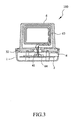
- Fig. 3 is a sectional view taken along line 3-3 of Fig. 1.
- the wireless signal transceiver unit which is generally denoted a numeral reference 100, includes a base 1 defining an internal space 11 and an upper open area 12; a circuit board 2 mounted in the internal space 11 of the base 1 for various necessary electronic components and connectors to mount thereon; a support plate 3 mounted in the upper open area 12 of the base 1; a pivot mechanism 4 provided on the support plate 3 and including a central through hole 41; an annular decorative cover 5 for covering an upper peripheral area of the support plate 3; and a rotatable antenna assembly 6 rotatably connected to the pivot mechanism 4 to locate on and upward protrude from the support plate 3.
- the connectors provided on the circuit board 2 include at least a plug jack 21 for receiving a plug pin 23 on a power cord, so that power could be supplied from an external power source to the circuit board 2; and a female connector 22, such as a USB connector, for receiving a male connector 24 on a signal cable for transmitting signals.
- the support plate 3 is provided at a predetermined position with a wireless signal intensity indicating unit 31, which includes a plurality of light-emitting elements 32 showing different brightness or colors to indicate the intensity or strength of the received wireless signal.
- the light-emitting elements 32 are spaced along the upper peripheral area of the support plate 3 and covered by the annular decorative cover 5, such that light emitted from any one of the light-emitting elements 32 can penetrate through the annular decorative cover 5 and project outward, allowing a user to observe the wireless signal intensity indicating unit 31 from an outer side of the annular decorative cover 5 and know the intensity of the wireless signal received via the antenna assembly 6.
- the annular decorative cover 5 may be further provided at an outer surface with legible marks 51, such as numbers, corresponding to the light-emitting elements 32 to serve as a visual aid to check the intensity of received wireless signal.
- the antenna assembly 6 is a WiMax antenna module having a plate-shaped body upright seated on a circular disk 61.
- the circular disk 61 is provided at a bottom side with a pivot cup 62 for fitly engaging with and rotatably seating on the pivot mechanism 4. Whereby, the antenna assembly 6 may be manually rotated about the pivot mechanism 4 toward a desired direction.
- the pivot mechanism 4 is mainly used as a supporting member to carry and support the antenna assembly 6 while allowing the antenna assembly 6 to rotate about the pivot mechanism 4. It is understood any other structure that is functionally equivalent to the pivot mechanism 4 can be used in the present invention to replace the pivot mechanism 4.
- the antenna assembly 6 may be rotatable relative to the base 1 through correspondingly molded pivot shafts, or other equivalent pivotal bearing structures other than the illustrated pivot mechanism 4.
- the antenna assembly 6 is internally provided with an antenna coil 63 for receiving radio waves of a given frequency.
- the antenna coil 63 is connected to predetermined contacts on the circuit board 2 via a pair of signal transmission cables 64, which are extended through the through hole 41 of the pivot mechanism 4.
- the rotatable antenna assembly 6 may be differently formed into any desired or suitable structure and/or configuration, or be differently decorated.
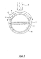
- the wireless signal transceiver unit 100 of the present invention When the wireless signal transceiver unit 100 of the present invention is used without rotating the antenna assembly 6 toward a direction of a wireless signal source S, as shown in Fig. 4, it would not be able to provide good wireless signal receiving effect. At this point, a user may easily manually rotate the antenna assembly 6 until the antenna assembly 6 is directed toward a direction in which the best signal receiving effect can be achieved, as shown in Fig. 5. The user may observe the lighting status of the light-emitting elements 32 while rotating the antenna assembly 6, so as to know the intensity of the received wireless signal and quickly accurately adjust the antenna assembly 6 to the direction best for receiving the wireless signal.
- Fig. 6 is a block diagram showing the circuits of the wireless signal transceiver unit 100 of the present invention.
- a wireless signal is received via the antenna coil 63, and then sent to a wireless signal receiving/transmitting circuit 65 via the signal transmission cables 64.
- the received signal is further sent from the wireless signal receiving/transmitting circuit 65 to a wireless signal processing circuit 66, which is connected to a wireless signal intensity detecting circuit 67 for detecting the intensity of the received wireless signal.
- the detected signal intensity is indicated by the on/off status of the light-emitting elements 32 of the wireless signal intensity indicating unit 31.
- the present invention is equipped with a turning mechanism for adjusting antenna direction, which allows a user to conveniently manually rotate the antenna assembly 6 of the wireless signal transceiver unit 100 toward a direction best for receiving a wireless signal.
- the wireless signal is transmitted from a different direction, or when the wireless signal transceiver unit 100 is moved to a different place, the user may easily search for the correct direction of the wireless signal source simply by manually turning the plate-like body of the rotatable antenna assembly 6 toward a desired direction in which a relatively high signal intensity is shown.
- the present invention is also characterized by the light-emitting elements 32 serving as the signal intensity indicators.
- the user may turn the antenna assembly 6 while observing the on/off of the light-emitting elements 32 to tell the signal intensity at different antenna directions, and thereby quickly and accurately find the direction best for receiving the wireless signal.
Landscapes
- Variable-Direction Aerials And Aerial Arrays (AREA)
- Support Of Aerials (AREA)
Abstract
Description
- The present invention relates to a wireless signal transceiver unit, and more particularly, to a wireless signal transceiver unit with turning mechanism for adjusting antenna direction.
- Due to the currently highly developed wireless signal transmission technique that provides the advantages of no wiring, wide operating areas, good security system, etc., most modem offices or commercial environments would utilize the wireless signal network to receive and transmit signals.
- In the architecture for the currently available wireless signal network, a wireless signal transceiver and a wireless network card are generally included. The former is an intermedium functioning like a hub of a cabled local area network to correctly transmit signals to a destination, and accept signals sent from the destination. The latter is mounted on a client apparatus, such as a computer and personal digital assistant (PDA), to link the client apparatus to the wireless signal transceiver for transferring data. With the maturity of the wireless network technique and the popularization of the wireless network environments, there are more and more different types of wireless signal transceiver products introduced into markets.
- For the wireless signal transceiver to function, an antenna must be provided thereon. Most of the conventional wireless signal transceivers have a pole antenna, which is workable to receive and transmit wireless signals in most cases. However, the conventional wireless signal transceivers frequently have the problem of poor signal receiving when relatively high antenna directionality is required to receive the wireless signal.
- It is known that Wimax is an abbreviation of Worldwide Interoperability for Microwave Access, a certification mark for products that pass conformity and interoperability tests for the IEEE 802.16 standards. Taking the Wimax antenna module as an example, it is currently widely used in many office environments. However, it is largely dependent on the antenna directionality. This type of antenna module is easily interfered by various factors, such as antenna radiation pattern, environmental changes such as barriers, refraction of radio frequency (RF), and reflection of RF, etc., to hinder the signal transceiver from performing normally. To adjust the antenna direction, a user has to inconveniently turn or move the whole wireless signal transceiver to different places.
- Moreover, the conventional wireless signal transceivers have not any device provided thereon for telling a user the intensity of a wireless signal being received. Thus, in most cases, the user is not able to determine which direction is best for the antenna to receive a wireless signal.
- A primary object of the present invention is to provide a wireless signal transceiver unit with turning mechanism for adjusting antenna direction to enable a user to adjust the antenna direction of the signal transceiver unit depending on the actual site in which the antenna operates.
- Another object of the present invention is to provide a turning mechanism for adjusting antenna direction, which is rotatably associated with a wireless signal transceiver unit. When it is desired to adjust an antenna of the signal transceiver unit toward a direction best for receiving a wireless signal, simply turns a plate-shaped body of the antenna relative to a base of the signal transceiver unit without the need of moving the whole signal transceiver unit.
- A further object of the present invention is to provide a wireless signal transceiver unit with signal intensity indicating unit, so that a user may turn a rotatable antenna assembly of the signal transceiver unit while observing the on/off of lights included in the signal intensity indicating unit to quickly and accurately find the direction best for receiving a wireless signal.
- The structure and the technical means adopted by the present invention to achieve the above and other objects can be best understood by referring to the following detailed description of the preferred embodiments and the accompanying drawings, wherein
- Fig. 1 is an assembled perspective view of a wireless signal transceiver unit with turning mechanism for adjusting antenna direction according to a preferred embodiment of the present invention;
- Fig. 2 is an exploded perspective view of Fig. 1;
- Fig. 3 is sectional view taken along line 3-3 of Fig. 1;
- Fig. 4 shows an antenna of the wireless signal transceiver unit of the present invention before being directed toward a wireless signal source;
- Fig. 5 shows the antenna of the wireless signal transceiver unit of the present invention after being turned to direct toward a wireless signal source; and
- Fig. 6 is a block diagram showing the circuits of the wireless signal transceiver unit of the present invention.
- Please refer to Figs. 1 and 2 that are assembled and exploded perspective views, respectively, of a wireless signal transceiver unit with turning mechanism for adjusting antenna direction according to a preferred embodiment of the present invention, and to Fig. 3 that is a sectional view taken along line 3-3 of Fig. 1. As shown, the wireless signal transceiver unit, which is generally denoted a
numeral reference 100, includes abase 1 defining aninternal space 11 and an upperopen area 12; acircuit board 2 mounted in theinternal space 11 of thebase 1 for various necessary electronic components and connectors to mount thereon; asupport plate 3 mounted in the upperopen area 12 of thebase 1; apivot mechanism 4 provided on thesupport plate 3 and including a central throughhole 41; an annulardecorative cover 5 for covering an upper peripheral area of thesupport plate 3; and arotatable antenna assembly 6 rotatably connected to thepivot mechanism 4 to locate on and upward protrude from thesupport plate 3. - The connectors provided on the
circuit board 2 include at least aplug jack 21 for receiving aplug pin 23 on a power cord, so that power could be supplied from an external power source to thecircuit board 2; and afemale connector 22, such as a USB connector, for receiving amale connector 24 on a signal cable for transmitting signals. - The
support plate 3 is provided at a predetermined position with a wireless signalintensity indicating unit 31, which includes a plurality of light-emittingelements 32 showing different brightness or colors to indicate the intensity or strength of the received wireless signal. - In the preferred embodiment of the present invention, the light-
emitting elements 32 are spaced along the upper peripheral area of thesupport plate 3 and covered by the annulardecorative cover 5, such that light emitted from any one of the light-emittingelements 32 can penetrate through the annulardecorative cover 5 and project outward, allowing a user to observe the wireless signalintensity indicating unit 31 from an outer side of the annulardecorative cover 5 and know the intensity of the wireless signal received via theantenna assembly 6. The annulardecorative cover 5 may be further provided at an outer surface withlegible marks 51, such as numbers, corresponding to the light-emittingelements 32 to serve as a visual aid to check the intensity of received wireless signal. - In the preferred embodiment of the present invention, the
antenna assembly 6 is a WiMax antenna module having a plate-shaped body upright seated on acircular disk 61. Thecircular disk 61 is provided at a bottom side with apivot cup 62 for fitly engaging with and rotatably seating on thepivot mechanism 4. Whereby, theantenna assembly 6 may be manually rotated about thepivot mechanism 4 toward a desired direction. - The
pivot mechanism 4 is mainly used as a supporting member to carry and support theantenna assembly 6 while allowing theantenna assembly 6 to rotate about thepivot mechanism 4. It is understood any other structure that is functionally equivalent to thepivot mechanism 4 can be used in the present invention to replace thepivot mechanism 4. - It would be obvious to a person of ordinary skill in the art that the
antenna assembly 6 may be rotatable relative to thebase 1 through correspondingly molded pivot shafts, or other equivalent pivotal bearing structures other than the illustratedpivot mechanism 4. - As can be seen from Fig. 3, the
antenna assembly 6 is internally provided with anantenna coil 63 for receiving radio waves of a given frequency. Theantenna coil 63 is connected to predetermined contacts on thecircuit board 2 via a pair ofsignal transmission cables 64, which are extended through the throughhole 41 of thepivot mechanism 4. In practical applications of the present invention, therotatable antenna assembly 6 may be differently formed into any desired or suitable structure and/or configuration, or be differently decorated. - When the wireless
signal transceiver unit 100 of the present invention is used without rotating theantenna assembly 6 toward a direction of a wireless signal source S, as shown in Fig. 4, it would not be able to provide good wireless signal receiving effect. At this point, a user may easily manually rotate theantenna assembly 6 until theantenna assembly 6 is directed toward a direction in which the best signal receiving effect can be achieved, as shown in Fig. 5. The user may observe the lighting status of the light-emitting elements 32 while rotating theantenna assembly 6, so as to know the intensity of the received wireless signal and quickly accurately adjust theantenna assembly 6 to the direction best for receiving the wireless signal. - Fig. 6 is a block diagram showing the circuits of the wireless
signal transceiver unit 100 of the present invention. As shown, a wireless signal is received via theantenna coil 63, and then sent to a wireless signal receiving/transmittingcircuit 65 via thesignal transmission cables 64. The received signal is further sent from the wireless signal receiving/transmittingcircuit 65 to a wirelesssignal processing circuit 66, which is connected to a wireless signalintensity detecting circuit 67 for detecting the intensity of the received wireless signal. The detected signal intensity is indicated by the on/off status of the light-emittingelements 32 of the wireless signalintensity indicating unit 31. - Unlike the wireless signal transceiver of prior art, the present invention is equipped with a turning mechanism for adjusting antenna direction, which allows a user to conveniently manually rotate the
antenna assembly 6 of the wirelesssignal transceiver unit 100 toward a direction best for receiving a wireless signal. When the wireless signal is transmitted from a different direction, or when the wirelesssignal transceiver unit 100 is moved to a different place, the user may easily search for the correct direction of the wireless signal source simply by manually turning the plate-like body of therotatable antenna assembly 6 toward a desired direction in which a relatively high signal intensity is shown. - The present invention is also characterized by the light-emitting
elements 32 serving as the signal intensity indicators. The user may turn theantenna assembly 6 while observing the on/off of the light-emittingelements 32 to tell the signal intensity at different antenna directions, and thereby quickly and accurately find the direction best for receiving the wireless signal.
Claims (12)
- A wireless signal transceiver unit (100), comprising:a base (1) having a support plate (3) mounted therein;a rotatable antenna assembly (6) provided with at least one antenna coil (63); anda pivot mechanism (4) being provided between the rotatable antenna assembly (6) and the support plate (3) to rotatably support the antenna assembly (6) on the base (1), such that the antenna assembly (6) is rotably operatable about the pivot mechanism (4) toward a selected direction relative to the base (1).
- The wireless signal transceiver unit (100) as claimed in claim 1, wherein the rotatable antenna assembly (6) comprises a plate-like antenna body upright located on a circular disk (61).
- The wireless signal transceiver unit (100) as claimed in claim 1, further comprising a wireless signal intensity indicating unit (31) provided on the support plate (3) for indicating an intensity of a wireless signal received via the antenna coil (63) of the rotatable antenna assembly (6).
- The wireless signal transceiver unit (100) as claimed in claim 3, further comprising a decorative cover (5) provided on the support plate (3), and wherein the wireless signal intensity indicating unit (31) comprises at least one light-emitting element (32) which generates a light projecting toward the decorative cover (5).
- The wireless signal transceiver unit as claimed in claim 4, wherein the decorative cover (5) is further provided with at least one legible mark (51) thereon to visually check the intensity of the received wireless signal.
- The wireless signal transceiver unit as claimed in claim 1, wherein the rotatable antenna assembly (6) is a Wimax antenna module.
- A wireless signal transceiver unit (100), comprising:a base (1); anda rotatable antenna assembly (6) provided with at least one antenna coil (63) and rotably supported by the base (1), such that the antenna assembly (6) is rotably operatable toward a selected direction relative to the base (1).
- The wireless signal transceiver unit (100) as claimed in claim 7, wherein the rotatable antenna assembly (6) comprises a plate-like antenna body upright located on a circular disk (61).
- The wireless signal transceiver unit (100) as claimed in claim 7, further comprising a wireless signal intensity indicating unit (31) provided on the support plate (3) for indicating an intensity of a wireless signal received via the antenna coil (63) of the rotatable antenna assembly (6).
- The wireless signal transceiver unit (100) as claimed in claim 7, further comprising a decorative cover (5) provided on the support plate (3), and wherein the wireless signal intensity indicating unit (31) further comprising at least one light-emitting element (32) which generates a light projecting toward the decorative cover (5).
- The wireless signal transceiver unit as claimed in claim 7, wherein the decorative cover (5) is further provided with at least one legible mark (51) thereon to visually check the intensity of the received wireless signal.
- The wireless signal transceiver unit (100) as claimed in claim 7, wherein the rotatable antenna assembly (6) is a Wimax antenna module.
Priority Applications (4)
| Application Number | Priority Date | Filing Date | Title |
|---|---|---|---|
| TW094143712A TWI285978B (en) | 2005-12-09 | 2005-12-09 | Wireless signal transceiver unit with rotating mechanism for adjusting antenna direction thereof |
| CNA2005100228358A CN1983717A (en) | 2005-12-09 | 2005-12-15 | Wireless signal transceiving device with antenna pointing and rotating mechanism |
| US11/337,538 US7672687B2 (en) | 2005-12-09 | 2006-01-24 | Wireless signal transceiver unit with turning mechanism for adjusting antenna direction thereof |
| EP06001708A EP1814194A1 (en) | 2005-12-09 | 2006-01-27 | Wireless signal transceiver unit with turning mechanism for adjusting antenna direction thereof |
Applications Claiming Priority (3)
| Application Number | Priority Date | Filing Date | Title |
|---|---|---|---|
| TW094143712A TWI285978B (en) | 2005-12-09 | 2005-12-09 | Wireless signal transceiver unit with rotating mechanism for adjusting antenna direction thereof |
| CNA2005100228358A CN1983717A (en) | 2005-12-09 | 2005-12-15 | Wireless signal transceiving device with antenna pointing and rotating mechanism |
| EP06001708A EP1814194A1 (en) | 2005-12-09 | 2006-01-27 | Wireless signal transceiver unit with turning mechanism for adjusting antenna direction thereof |
Publications (1)
| Publication Number | Publication Date |
|---|---|
| EP1814194A1 true EP1814194A1 (en) | 2007-08-01 |
Family
ID=42671573
Family Applications (1)
| Application Number | Title | Priority Date | Filing Date |
|---|---|---|---|
| EP06001708A Withdrawn EP1814194A1 (en) | 2005-12-09 | 2006-01-27 | Wireless signal transceiver unit with turning mechanism for adjusting antenna direction thereof |
Country Status (4)
| Country | Link |
|---|---|
| US (1) | US7672687B2 (en) |
| EP (1) | EP1814194A1 (en) |
| CN (1) | CN1983717A (en) |
| TW (1) | TWI285978B (en) |
Families Citing this family (19)
| Publication number | Priority date | Publication date | Assignee | Title |
|---|---|---|---|---|
| USD880444S1 (en) * | 1920-10-31 | 2020-04-07 | Signify Holding B.V. | Telecommunication apparatus |
| TWD118690S1 (en) * | 2005-12-09 | 2007-08-21 | 神基科技股份有限公司 | Wireless signal transceiver |
| US7375961B2 (en) * | 2006-06-28 | 2008-05-20 | International Business Machines Corporation | Rotatable component support assembly for an electronics enclosure |
| USD580917S1 (en) * | 2008-02-20 | 2008-11-18 | Cheng Uei Precision Industry Co., Ltd. | Antenna apparatus |
| USD684563S1 (en) * | 2011-04-07 | 2013-06-18 | Jean L. Meek | Low drag antenna |
| US9436221B2 (en) | 2014-11-05 | 2016-09-06 | Balaji Raghunathan | Multiple connector electronics docking base device |
| TWD170414S (en) * | 2015-01-13 | 2015-09-11 | 友勁科技股份有限公司 | wireless receiver |
| CA175922S (en) * | 2017-03-07 | 2018-03-29 | Michael Cummings | Cover for antenna |
| USD933002S1 (en) * | 2018-11-26 | 2021-10-12 | Oticon A/S | Battery charger |
| USD918449S1 (en) * | 2019-03-19 | 2021-05-04 | Balaji Raghunathan | Combination lamp and charging station |
| US10601973B1 (en) | 2019-03-19 | 2020-03-24 | Balaji Raghunathan | Multiple connector electronics docking device |
| USD918450S1 (en) * | 2019-03-19 | 2021-05-04 | Balaji Raghunathan | Combination lamp, speaker, and charging station |
| USD892043S1 (en) | 2019-03-19 | 2020-08-04 | Balaji Raghunathan | Charging station |
| CN111010204B (en) * | 2019-11-22 | 2021-07-23 | Oppo广东移动通信有限公司 | customer terminal equipment |
| CN111106448B (en) * | 2019-11-22 | 2021-10-19 | Oppo广东移动通信有限公司 | customer terminal equipment |
| CN111010203B (en) * | 2019-11-22 | 2021-10-26 | Oppo广东移动通信有限公司 | Client terminal device |
| TWM599406U (en) * | 2020-02-20 | 2020-08-01 | 貿聯國際股份有限公司 | Docking station |
| CN111355541A (en) * | 2020-04-02 | 2020-06-30 | Oppo广东移动通信有限公司 | Network equipment, method for searching for network signals |
| CN118431713B (en) * | 2023-10-12 | 2025-06-13 | 顶坚(深圳)通讯技术有限公司 | A 5G communication antenna test stand |
Citations (6)
| Publication number | Priority date | Publication date | Assignee | Title |
|---|---|---|---|---|
| US1666480A (en) * | 1924-12-09 | 1928-04-17 | Music Master Corp | Means for adjusting the antenna of radio apparatus |
| US5903237A (en) * | 1995-12-20 | 1999-05-11 | Hughes Electronics Corporation | Antenna pointing aid |
| US5949379A (en) * | 1998-01-12 | 1999-09-07 | Alpha Telecom Inc. | Microwave antenna device on PCMCIA network cards for notebook computers |
| DE20120650U1 (en) * | 2001-12-20 | 2002-04-04 | Trans Electric Co., Ltd., Hua Tan Hsiang, Changhua | Indoor antenna with automatic channel search and memory function |
| WO2004079861A1 (en) * | 2003-03-06 | 2004-09-16 | Raysat Cyprus Limited | Flat mobile antenna system |
| US20040227684A1 (en) * | 2003-02-25 | 2004-11-18 | Ten-Long Deng | Directional antenna apparatus |
Family Cites Families (19)
| Publication number | Priority date | Publication date | Assignee | Title |
|---|---|---|---|---|
| JPS5861554U (en) * | 1981-10-20 | 1983-04-25 | ソニー株式会社 | transceiver |
| US4543584A (en) * | 1983-04-18 | 1985-09-24 | General Electric Company | Collapsible magnetic antenna mount |
| US5555459A (en) * | 1992-03-27 | 1996-09-10 | Norand Corporation | Antenna means for hand-held data terminals |
| US5841402A (en) * | 1992-03-27 | 1998-11-24 | Norand Corporation | Antenna means for hand-held radio devices |
| US5444737A (en) * | 1993-05-05 | 1995-08-22 | National Semiconductor Corporation | Wireless data transceiver |
| US5884197A (en) * | 1995-11-30 | 1999-03-16 | Lucent Technologies Inc. | Wireless portable transceiver arranged for providing isolation between radio frequency and audio signals |
| US6236674B1 (en) * | 1996-02-23 | 2001-05-22 | Teletransactions, Inc. | Transceiver control with sleep mode operation |
| US6087933A (en) * | 1996-05-20 | 2000-07-11 | Pittway Corporation | Antenna switching for amplitude degradation during supervision and installation of wireless security systems |
| US5969689A (en) * | 1997-01-13 | 1999-10-19 | Metawave Communications Corporation | Multi-sector pivotal antenna system and method |
| US6108526A (en) * | 1997-05-07 | 2000-08-22 | Lucent Technologies, Inc. | Antenna system and method thereof |
| US6140970A (en) * | 1999-04-30 | 2000-10-31 | Nokia Mobile Phones Limited | Radio antenna |
| JP2001127516A (en) * | 1999-10-25 | 2001-05-11 | Nec Corp | Portable wireless device |
| US6259410B1 (en) * | 2000-09-11 | 2001-07-10 | Tranwo Technology Corp. | Angle adjusting mechanism for antenna |
| US6683581B2 (en) * | 2000-12-29 | 2004-01-27 | Bellsouth Intellectual Property Corporation | Antenna alignment devices |
| US6853353B2 (en) * | 2002-11-12 | 2005-02-08 | Accton Technology Corporation | Antenna assembly for use with a portable computing device wireless communication |
| US6816121B1 (en) * | 2003-06-18 | 2004-11-09 | Benq Corporation | Motorized rotatable wireless antenna |
| US6977624B1 (en) * | 2003-10-17 | 2005-12-20 | Szente Pedro A | Antenna directivity enhancer |
| WO2005072137A2 (en) * | 2004-01-16 | 2005-08-11 | Two Technologies, Inc. | Radio frequency identification device with movable antenna |
| US7019703B2 (en) * | 2004-05-07 | 2006-03-28 | Andrew Corporation | Antenna with Rotatable Reflector |
-
2005
- 2005-12-09 TW TW094143712A patent/TWI285978B/en not_active IP Right Cessation
- 2005-12-15 CN CNA2005100228358A patent/CN1983717A/en active Pending
-
2006
- 2006-01-24 US US11/337,538 patent/US7672687B2/en not_active Expired - Fee Related
- 2006-01-27 EP EP06001708A patent/EP1814194A1/en not_active Withdrawn
Patent Citations (6)
| Publication number | Priority date | Publication date | Assignee | Title |
|---|---|---|---|---|
| US1666480A (en) * | 1924-12-09 | 1928-04-17 | Music Master Corp | Means for adjusting the antenna of radio apparatus |
| US5903237A (en) * | 1995-12-20 | 1999-05-11 | Hughes Electronics Corporation | Antenna pointing aid |
| US5949379A (en) * | 1998-01-12 | 1999-09-07 | Alpha Telecom Inc. | Microwave antenna device on PCMCIA network cards for notebook computers |
| DE20120650U1 (en) * | 2001-12-20 | 2002-04-04 | Trans Electric Co., Ltd., Hua Tan Hsiang, Changhua | Indoor antenna with automatic channel search and memory function |
| US20040227684A1 (en) * | 2003-02-25 | 2004-11-18 | Ten-Long Deng | Directional antenna apparatus |
| WO2004079861A1 (en) * | 2003-03-06 | 2004-09-16 | Raysat Cyprus Limited | Flat mobile antenna system |
Also Published As
| Publication number | Publication date |
|---|---|
| US7672687B2 (en) | 2010-03-02 |
| US20070135157A1 (en) | 2007-06-14 |
| TW200723588A (en) | 2007-06-16 |
| TWI285978B (en) | 2007-08-21 |
| CN1983717A (en) | 2007-06-20 |
Similar Documents
| Publication | Publication Date | Title |
|---|---|---|
| US7672687B2 (en) | Wireless signal transceiver unit with turning mechanism for adjusting antenna direction thereof | |
| US6424442B1 (en) | Optical transmitter and transceiver module for wireless data transmission | |
| US6509876B1 (en) | Antenna for wireless communication system | |
| US6587698B1 (en) | Plug-in communication card | |
| US20080258876A1 (en) | Distributed Antenna Array With Centralized Data Hub For Determining Presence And Location Of RF Tags | |
| JPH08107369A (en) | Plug-in wireless module for operating with a portable host device capable of wireless communication | |
| JP2025500232A (en) | Antenna array and signal processing for an RFID tag reader - Patents.com | |
| US20110165792A1 (en) | Configuration aid for orienting a connector with respect to a receptacle | |
| WO2015174786A1 (en) | Apparatus for measuring antenna radiation pattern | |
| US7928895B2 (en) | Systems and methods for communication to a gimbal mounted device | |
| US10467909B2 (en) | Automatic dependent surveillance broadcast system beacon and method | |
| US20130029600A1 (en) | Wireless communication system | |
| DE69622678T2 (en) | Combined diffuser and directive infrared transceiver | |
| US6486994B1 (en) | Multi-directional infrared port and methods of using same | |
| US6646612B1 (en) | Non-directivity antenna for wireless LAN | |
| JP2002342025A (en) | Input device | |
| EP4407805A1 (en) | Radio system for high-speed wireless communication | |
| JP2009504093A (en) | Antenna system | |
| US20050082368A1 (en) | Wireless communication system capable of visually indicating failure of transmission and reception states | |
| US20050049014A1 (en) | Wireless local area network device | |
| EP0849896B1 (en) | Transceiver module for wireless data transmission | |
| US10897282B2 (en) | Systems and methods for determining cable end location | |
| WO2006052386A2 (en) | Distributed antenna array with centralized data hub for determining presence and location of rf tags | |
| DE102017116327A1 (en) | Electrical installation device, system for implementing a smart home and method for operating such a system | |
| US20210341116A1 (en) | Illuminating emergency response system |
Legal Events
| Date | Code | Title | Description |
|---|---|---|---|
| PUAI | Public reference made under article 153(3) epc to a published international application that has entered the european phase |
Free format text: ORIGINAL CODE: 0009012 |
|
| AK | Designated contracting states |
Kind code of ref document: A1 Designated state(s): AT BE BG CH CY CZ DE DK EE ES FI FR GB GR HU IE IS IT LI LT LU LV MC NL PL PT RO SE SI SK TR |
|
| AX | Request for extension of the european patent |
Extension state: AL BA HR MK YU |
|
| 17P | Request for examination filed |
Effective date: 20080107 |
|
| 17Q | First examination report despatched |
Effective date: 20080221 |
|
| AKX | Designation fees paid |
Designated state(s): DE FR GB |
|
| RAP1 | Party data changed (applicant data changed or rights of an application transferred) |
Owner name: GETAC TECHNOLOGY CORPORATION |
|
| STAA | Information on the status of an ep patent application or granted ep patent |
Free format text: STATUS: THE APPLICATION IS DEEMED TO BE WITHDRAWN |
|
| 18D | Application deemed to be withdrawn |
Effective date: 20100916 |