EP1814097A2 - AAA model for fatigue testing - Google Patents
AAA model for fatigue testing Download PDFInfo
- Publication number
- EP1814097A2 EP1814097A2 EP07250162A EP07250162A EP1814097A2 EP 1814097 A2 EP1814097 A2 EP 1814097A2 EP 07250162 A EP07250162 A EP 07250162A EP 07250162 A EP07250162 A EP 07250162A EP 1814097 A2 EP1814097 A2 EP 1814097A2
- Authority
- EP
- European Patent Office
- Prior art keywords
- test apparatus
- model
- rapid prototyping
- flexible
- present
- Prior art date
- Legal status (The legal status is an assumption and is not a legal conclusion. Google has not performed a legal analysis and makes no representation as to the accuracy of the status listed.)
- Withdrawn
Links
Images

Classifications
-
- G—PHYSICS
- G09—EDUCATION; CRYPTOGRAPHY; DISPLAY; ADVERTISING; SEALS
- G09B—EDUCATIONAL OR DEMONSTRATION APPLIANCES; APPLIANCES FOR TEACHING, OR COMMUNICATING WITH, THE BLIND, DEAF OR MUTE; MODELS; PLANETARIA; GLOBES; MAPS; DIAGRAMS
- G09B23/00—Models for scientific, medical, or mathematical purposes, e.g. full-sized devices for demonstration purposes
- G09B23/06—Models for scientific, medical, or mathematical purposes, e.g. full-sized devices for demonstration purposes for physics
- G09B23/08—Models for scientific, medical, or mathematical purposes, e.g. full-sized devices for demonstration purposes for physics for statics or dynamics
- G09B23/10—Models for scientific, medical, or mathematical purposes, e.g. full-sized devices for demonstration purposes for physics for statics or dynamics of solid bodies
-
- B—PERFORMING OPERATIONS; TRANSPORTING
- B33—ADDITIVE MANUFACTURING TECHNOLOGY
- B33Y—ADDITIVE MANUFACTURING, i.e. MANUFACTURING OF THREE-DIMENSIONAL [3D] OBJECTS BY ADDITIVE DEPOSITION, ADDITIVE AGGLOMERATION OR ADDITIVE LAYERING, e.g. BY 3D PRINTING, STEREOLITHOGRAPHY OR SELECTIVE LASER SINTERING
- B33Y70/00—Materials specially adapted for additive manufacturing
-
- G—PHYSICS
- G09—EDUCATION; CRYPTOGRAPHY; DISPLAY; ADVERTISING; SEALS
- G09B—EDUCATIONAL OR DEMONSTRATION APPLIANCES; APPLIANCES FOR TEACHING, OR COMMUNICATING WITH, THE BLIND, DEAF OR MUTE; MODELS; PLANETARIA; GLOBES; MAPS; DIAGRAMS
- G09B23/00—Models for scientific, medical, or mathematical purposes, e.g. full-sized devices for demonstration purposes
- G09B23/28—Models for scientific, medical, or mathematical purposes, e.g. full-sized devices for demonstration purposes for medicine
- G09B23/30—Anatomical models
-
- B—PERFORMING OPERATIONS; TRANSPORTING
- B33—ADDITIVE MANUFACTURING TECHNOLOGY
- B33Y—ADDITIVE MANUFACTURING, i.e. MANUFACTURING OF THREE-DIMENSIONAL [3D] OBJECTS BY ADDITIVE DEPOSITION, ADDITIVE AGGLOMERATION OR ADDITIVE LAYERING, e.g. BY 3D PRINTING, STEREOLITHOGRAPHY OR SELECTIVE LASER SINTERING
- B33Y80/00—Products made by additive manufacturing
Definitions
- the present invention relates to both a method of manufacturing a model or test apparatus and the model or test apparatus itself.
- the test apparatus fabricated in accordance with the present invention is designed to be a component used in a durability and fatigue testing unit, most preferably for the testing of a vascular prosthesis. More specifically, the present invention is directed to a method of making a life-size anatomically correct model of an Abdominal Aortic Aneurysm (AAA) with any suitable rapid prototyping (RP) process that creates solid freeform parts with flexible material.
- the preferred RP processes used in making the test apparatus of the present invention is Selective Laser Sintering (SLS).
- SLS Selective Laser Sintering
- the present invention is also directed to the AAA model produced by said methods and its use as a component in a vascular durability and fatigue testing unit.
- the aorta is the body's largest artery, having roughly the diameter of a garden hose, and is the blood vessel that carries oxygen-rich blood away from the heart.
- the aorta extends from the heart down through the chest and the abdominal region, dividing into two smaller blood vessels that provide blood to the pelvis and legs.
- An aortic aneurysm is an abnormal bulge that can occur anywhere along the wall of the aorta. Most aortic aneurysms, about 75%, arise in the section running through one's abdomen and are thus referred to as "abdominal aneurysms". Other aortic aneurysms, referred to as "thoracic aneurysms", occur in the section of the aorta running through one's chest.
- an aortic aneurysm causes life-threatening internal bleeding.
- an aneurysm is, the higher the risk of it rupturing.
- the surgical treatment of an aneurysm typically involves the use of a replacement vessel or an artificial prosthesis following the excision of the aneurysm.
- stress can be relieved in the affected vessel by implanting a supporting structure such as a stent or other intravascular device therein.
- Implantable devices are well known in the art and include stents, grafts, stent-grafts, catheters, embolic coils, filters and cannulas.
- US-6,810,751 to Moreno et al. describes a method and apparatus for testing the vascular durability and fatigue of a vascular prosthesis that simulates physiological loading conditions.
- One component in said apparatus is a fluid conduit manufactured to recreate the physical properties and characteristics of a vessel intended to receive the implantable device, e.g. a stent-graft.
- the fluid conduit is made of a transparent silicone elastomer and in one embodiment is bifurcated to correspond with the size and shape of a human aorta.
- US-6,511,325 to Lalka et al. also discloses an AAA model made of silicone.
- AAA models used in any sort of testing are made out of either blown glass or silicone tubing. Although able to be made to simulate the aorta to a certain degree in size and shape, such models are limiting in their construction due to their composition and method of manufacturing. That is, there is still a need to provide a method of forming an anatomically correct AAA model to be used in a fatigue and durability testing apparatus that allows the model or apparatus to be easily changed from the fabrication of one model to the next to match the desired anatomy of the patient being treated. The use of blown glass and/or silicone tubing does not afford such a luxury.
- the present invention is directed to the fabrication of a test apparatus and the test apparatus itself.
- the test apparatus is designed to be a component used in a durability/fatigue testing unit.
- One such test apparatus made in accordance with the present invention is a life-size model of an Abdominal Aortic Aneurysm made with any rapid prototyping process that creates solid freeform parts with flexible material.
- a preferred rapid prototyping process used to make the AAA model in accordance with the present invention is the process known as selective laser sintering (SLS), while the preferred material used in said process is an elastomeric polymer.
- SLS selective laser sintering
- Another preferred rapid prototyping process used to make the AAA model in accordance with the present invention is the process known as Stereolithography (SLA).
- the present invention is directed to a method of manufacturing a test apparatus, as well as the test apparatus itself.
- the majority of the description will be directed to the fabrication of a life-size model of an abdominal aortic aneurysm, it will be understood that the AAA region is not the only region that may be duplicated by the method of the present invention.
- the method of the present invention may also be used in the formation of models of other arteries, or even the heart, and used in a durability/fatigue unit to test devices to be used in connection with these regions.
- the present invention is directed to a method of making a life-size, anatomically correct model of an Abdominal Aortic Aneurysm (AAA) with any suitable rapid prototyping (RP) process that creates solid freeform parts with flexible material; however, the artisan should appreciate that the life-sized model could be scaled if appropriate.
- rapid prototyping methods it is possible to fabricate a structural body based directly on geometrical data of the structural body generated by a computer-aided design (CAD) program.
- CAD computer-aided design
- the first step in the manufacturing of the test apparatus in accordance with the present invention is the creation of a three-dimensional model of the AAA with a CAD program.
- the CAD program based on clinical data and measurements, determine the size of the AAA CAD model.
- Solidworks (“SolidWorks", Concord Mass.) was the CAD program used in the making of the AAA CAD model shown in Figure 1, however, other suitable CAD software packages, such as ProEngineer (Parametric Technologies, Waltham, Mass.) are known in the art and can be used to further process the digital model.
- the CAD system is essential in that it allows the test apparatus being fabricated to be changed to match the desired anatomy.
- the three-dimensional geometry in the CAD system can be modeled to have tortuous regions or not, or anatomy size can be larger or smaller.
- geometry imported from spiral CT scans of an AAA could be used to make the model.
- the elastic modulus of individual AAA models could potentially vary, one from the next, as desired.
- the present invention is building a life-size anatomically correct model of the patient's AAA.
- the second step in the method of manufacturing the test apparatus in accordance with the present invention is the creation of the test apparatus through any rapid prototyping method that has the capability to create flexible models.
- the process of rapid prototyping more recently referred to as a layer manufacturing (LM) process or a solid free-form fabrication (SFF) process, creates its product by building it up point-by-point or layer-by-layer.
- LM layer manufacturing
- SFF solid free-form fabrication
- SFF techniques include, but are not limited to, stereolithography, selective laser sintering, 3-D printing, inkjet printing, fused deposition modeling, laser powder forming and laminated object manufacturing.
- directions derived from three-dimensional CAD models drive these rapid prototyping processes. Consequently, CAD technologies are an essential enabling system for rapid prototyping.
- RP processes known in the art are based on different physical principles, they each essentially work by either using lasers to cut, cure or sinter material into a layer, or involve ejecting material from a nozzle to create a layer. Each method has advantages and disadvantages to be weighed and are known to those skilled in the art.
- SLS Selective Laser Sintering
- SLS was one RP method chosen because it offers a variety of different polymers to use and because it is very accurate when compared with other RP methods.
- SLS involves tracing a laser beam over the surface of a tightly compacted powder made of a thermoplastic material.
- a roller spreads the powder over the surface of a build cylinder.
- a piston moves down one object layer thickness to accommodate the layer of powder.
- Heat from the laser melts the powder where it strikes under guidance of a scanner system.
- a concentrated infrared heating beam is provided with the use of a CO 2 laser.
- the entire fabrication chamber is sealed and maintained at a temperature just below the melting point of the plastic powder. Accordingly, the heat from the laser need only elevate the temperature slightly to cause sintering.
- the piston is raised to elevate the object and any excess powder is brushed away. Any final manual finishing to the object can then be carried out as well.
- the flexible material to be used in the RP process of the present invention depends on the particular RP process being employed and are generally known in the art. Many different materials can be used and include, but are not limited to, thermopolymers, photopolymers, elastomeric polymers, other plastics, metallic powder, paper and wax.
- the material used in the SLS method to create the AAA model shown in Figure 2 in accordance with the present invention was an elastomeric polymer sold under the trade name Somos 201. Laser sintered prototypes made with elastomer are faster and cheaper than cast prototypes. They speed up the design process by allowing for errors to be corrected early on.
- the present invention is also directed to the AAA model produced by the rapid prototyping procedure.
- the use of a SFF method provides for the fabrication of models having complicated thin-walled parts.
- the flexible AAA model or test apparatus can in turn be used as a component in a fatigue and durability testing apparatus.
- the flexible AAA model made in accordance with the present invention can be used as a component in a testing unit for testing the durability and fatigue of vascular prostheses, such as stents and grafts.
- the testing unit would more fully simulate the various physiological stresses induced upon the vascular prosthesis and could be made to match the specific anatomy of a particular patient.
Landscapes
- Engineering & Computer Science (AREA)
- Physics & Mathematics (AREA)
- General Physics & Mathematics (AREA)
- Educational Administration (AREA)
- Mathematical Physics (AREA)
- Theoretical Computer Science (AREA)
- Educational Technology (AREA)
- Algebra (AREA)
- Computational Mathematics (AREA)
- Chemical & Material Sciences (AREA)
- Mathematical Analysis (AREA)
- Mathematical Optimization (AREA)
- Business, Economics & Management (AREA)
- Pure & Applied Mathematics (AREA)
- Medical Informatics (AREA)
- Health & Medical Sciences (AREA)
- General Health & Medical Sciences (AREA)
- Medicinal Chemistry (AREA)
- Manufacturing & Machinery (AREA)
- Materials Engineering (AREA)
- Prostheses (AREA)
- Sampling And Sample Adjustment (AREA)
- Investigating Strength Of Materials By Application Of Mechanical Stress (AREA)
Abstract
Description
- The present invention relates to both a method of manufacturing a model or test apparatus and the model or test apparatus itself. The test apparatus fabricated in accordance with the present invention is designed to be a component used in a durability and fatigue testing unit, most preferably for the testing of a vascular prosthesis. More specifically, the present invention is directed to a method of making a life-size anatomically correct model of an Abdominal Aortic Aneurysm (AAA) with any suitable rapid prototyping (RP) process that creates solid freeform parts with flexible material. The preferred RP processes used in making the test apparatus of the present invention is Selective Laser Sintering (SLS). The present invention is also directed to the AAA model produced by said methods and its use as a component in a vascular durability and fatigue testing unit.
- The aorta is the body's largest artery, having roughly the diameter of a garden hose, and is the blood vessel that carries oxygen-rich blood away from the heart. The aorta extends from the heart down through the chest and the abdominal region, dividing into two smaller blood vessels that provide blood to the pelvis and legs. An aortic aneurysm is an abnormal bulge that can occur anywhere along the wall of the aorta. Most aortic aneurysms, about 75%, arise in the section running through one's abdomen and are thus referred to as "abdominal aneurysms". Other aortic aneurysms, referred to as "thoracic aneurysms", occur in the section of the aorta running through one's chest.
- The rupturing of an aortic aneurysm causes life-threatening internal bleeding. Of course, the larger an aneurysm is, the higher the risk of it rupturing. Approximately 15,000 people die each year in the United States of a ruptured aortic aneurysm. If detected in time, an aortic aneurysm can usually be repaired by surgery. The surgical treatment of an aneurysm typically involves the use of a replacement vessel or an artificial prosthesis following the excision of the aneurysm. In other instances, stress can be relieved in the affected vessel by implanting a supporting structure such as a stent or other intravascular device therein. Implantable devices are well known in the art and include stents, grafts, stent-grafts, catheters, embolic coils, filters and cannulas.
- A major concern, however, in the use of a vascular prosthesis in treating AAA or any other problem is the fact that the device is being implanted within the aorta of the patient and is subjected to numerous physiological conditions for the remainder of it's life or the life of the patient. Accordingly, it is imperative that the fatigue and durability characteristics of the implantable device be subjected to sufficient testing for its intended use.
-
US-6,810,751 to Moreno et al. describes a method and apparatus for testing the vascular durability and fatigue of a vascular prosthesis that simulates physiological loading conditions. One component in said apparatus is a fluid conduit manufactured to recreate the physical properties and characteristics of a vessel intended to receive the implantable device, e.g. a stent-graft.US-6,810,751 , the fluid conduit is made of a transparent silicone elastomer and in one embodiment is bifurcated to correspond with the size and shape of a human aorta.US-6,511,325 to Lalka et al. also discloses an AAA model made of silicone. - The majority of AAA models used in any sort of testing are made out of either blown glass or silicone tubing. Although able to be made to simulate the aorta to a certain degree in size and shape, such models are limiting in their construction due to their composition and method of manufacturing. That is, there is still a need to provide a method of forming an anatomically correct AAA model to be used in a fatigue and durability testing apparatus that allows the model or apparatus to be easily changed from the fabrication of one model to the next to match the desired anatomy of the patient being treated. The use of blown glass and/or silicone tubing does not afford such a luxury.
- Accordingly, the present invention is directed to the fabrication of a test apparatus and the test apparatus itself. The test apparatus is designed to be a component used in a durability/fatigue testing unit. One such test apparatus made in accordance with the present invention is a life-size model of an Abdominal Aortic Aneurysm made with any rapid prototyping process that creates solid freeform parts with flexible material. A preferred rapid prototyping process used to make the AAA model in accordance with the present invention is the process known as selective laser sintering (SLS), while the preferred material used in said process is an elastomeric polymer. Another preferred rapid prototyping process used to make the AAA model in accordance with the present invention is the process known as Stereolithography (SLA).
- Embodiments of the invention will now be described by way of example with reference to the accompanying drawings, in which:
- Figure 1 is a photograph of the CAD model created in accordance with the present invention.
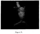
- Figure 2 is a photograph of a three-dimensional, life-size AAA model manufactured in accordance with the present invention using SLS technology.
- The present invention is directed to a method of manufacturing a test apparatus, as well as the test apparatus itself. Although the majority of the description will be directed to the fabrication of a life-size model of an abdominal aortic aneurysm, it will be understood that the AAA region is not the only region that may be duplicated by the method of the present invention. For example, the method of the present invention may also be used in the formation of models of other arteries, or even the heart, and used in a durability/fatigue unit to test devices to be used in connection with these regions.
- Accordingly, the present invention is directed to a method of making a life-size, anatomically correct model of an Abdominal Aortic Aneurysm (AAA) with any suitable rapid prototyping (RP) process that creates solid freeform parts with flexible material; however, the artisan should appreciate that the life-sized model could be scaled if appropriate. With the use of rapid prototyping methods it is possible to fabricate a structural body based directly on geometrical data of the structural body generated by a computer-aided design (CAD) program.
- Accordingly, the first step in the manufacturing of the test apparatus in accordance with the present invention is the creation of a three-dimensional model of the AAA with a CAD program. The CAD program, based on clinical data and measurements, determine the size of the AAA CAD model. Solidworks ("SolidWorks", Concord Mass.) was the CAD program used in the making of the AAA CAD model shown in Figure 1, however, other suitable CAD software packages, such as ProEngineer (Parametric Technologies, Waltham, Mass.) are known in the art and can be used to further process the digital model.
- The CAD system is essential in that it allows the test apparatus being fabricated to be changed to match the desired anatomy. For example, the three-dimensional geometry in the CAD system can be modeled to have tortuous regions or not, or anatomy size can be larger or smaller. Furthermore, geometry imported from spiral CT scans of an AAA could be used to make the model. Also, the elastic modulus of individual AAA models could potentially vary, one from the next, as desired. Basically, the present invention is building a life-size anatomically correct model of the patient's AAA.
- The second step in the method of manufacturing the test apparatus in accordance with the present invention is the creation of the test apparatus through any rapid prototyping method that has the capability to create flexible models. The process of rapid prototyping, more recently referred to as a layer manufacturing (LM) process or a solid free-form fabrication (SFF) process, creates its product by building it up point-by-point or layer-by-layer. The use of a SFF process allows one to fabricate components having a complex geometry which otherwise could not be made by traditional fabrication methods.
- Examples of SFF techniques include, but are not limited to, stereolithography, selective laser sintering, 3-D printing, inkjet printing, fused deposition modeling, laser powder forming and laminated object manufacturing. As indicated above, directions derived from three-dimensional CAD models drive these rapid prototyping processes. Consequently, CAD technologies are an essential enabling system for rapid prototyping. Although the various RP processes known in the art are based on different physical principles, they each essentially work by either using lasers to cut, cure or sinter material into a layer, or involve ejecting material from a nozzle to create a layer. Each method has advantages and disadvantages to be weighed and are known to those skilled in the art.
- The AAA model made in accordance with the present invention as shown in Figure 2 was created with the use of Selective Laser Sintering (SLS). SLS was one RP method chosen because it offers a variety of different polymers to use and because it is very accurate when compared with other RP methods. Generally, SLS involves tracing a laser beam over the surface of a tightly compacted powder made of a thermoplastic material. A roller spreads the powder over the surface of a build cylinder. A piston moves down one object layer thickness to accommodate the layer of powder. Heat from the laser melts the powder where it strikes under guidance of a scanner system. A concentrated infrared heating beam is provided with the use of a CO2 laser. The entire fabrication chamber is sealed and maintained at a temperature just below the melting point of the plastic powder. Accordingly, the heat from the laser need only elevate the temperature slightly to cause sintering. Following the full formation of the object, the piston is raised to elevate the object and any excess powder is brushed away. Any final manual finishing to the object can then be carried out as well.
- Another variable in the manufacturing of the test apparatus in accordance with the present invention is the flexible material to be used in the RP process. The flexible material to be used in the RP process of the present invention depends on the particular RP process being employed and are generally known in the art. Many different materials can be used and include, but are not limited to, thermopolymers, photopolymers, elastomeric polymers, other plastics, metallic powder, paper and wax. The material used in the SLS method to create the AAA model shown in Figure 2 in accordance with the present invention was an elastomeric polymer sold under the trade name Somos 201. Laser sintered prototypes made with elastomer are faster and cheaper than cast prototypes. They speed up the design process by allowing for errors to be corrected early on. This material has been proven to stand up to aggressive field tests with excellent results. Other preferred materials to be used with SLS are DuraFlex (Nylon 12 Unfilled) and DuraFlex (Nylon 12 Glass Filled), while 7545-Flex (High Detail and Accuracy) and DSM-14120 (High Strength ABS Like) are materials preferred to be used with stereolithography processes.
- The present invention is also directed to the AAA model produced by the rapid prototyping procedure. The use of a SFF method provides for the fabrication of models having complicated thin-walled parts. The flexible AAA model or test apparatus can in turn be used as a component in a fatigue and durability testing apparatus. For example, the flexible AAA model made in accordance with the present invention can be used as a component in a testing unit for testing the durability and fatigue of vascular prostheses, such as stents and grafts. With the use of the flexible AAA model made in accordance with the present invention in such a testing unit, the testing unit would more fully simulate the various physiological stresses induced upon the vascular prosthesis and could be made to match the specific anatomy of a particular patient.
Claims (14)
- A method of manufacturing a flexible test apparatus in accordance with a rapid prototyping process, said method comprising creating a three-dimensional model of the test apparatus with a CAD program and applying said rapid prototyping process using a flexible material to said three-dimensional model to create the flexible test apparatus.
- The method according to claim 1, wherein the test apparatus is a life-size, anatomically correct model of a specific organ or region of a mammal.
- The method according to claim 1, wherein the test apparatus is a scaled replica of a life-sized, anatomically correct model of a specific organ or region of a mammal.
- The method according to claim 2, wherein the life-size, anatomically correct model is an abdominal aortic aneurysm model.
- The method according to claim 2, wherein the mammal is a human.
- The method according to claim 1, wherein said rapid prototyping process is selected from the group consisting of stereolithography, selective laser sintering, 3-D printing, inkjet printing, fused deposition modeling and laminated object manufacturing.
- The method according to claim 1, wherein said rapid prototyping process is selective laser sintering.
- The method according to claim 1, wherein said flexible material is selected from the group consisting of thermopolymers, photopolymers, elastomeric polymers, metallic powder, paper and wax.
- The method according to claim 8, wherein said flexible material is an elastomeric polymer.
- The method according to claim 8, wherein said elastomeric polymer is Somos®201.
- A flexible three-dimensional test apparatus manufactured by the method of claim 1.
- The test apparatus of claim 11, wherein said test apparatus is an abdominal aortic aneurysm model.
- A fatigue and durability testing unit comprising a flexible test apparatus manufactured in accordance with the method of claim 1.
- The testing unit of claim 13, wherein said vascular prosthesis is selected from the group consisting of stents, grafts, stent-grafts, catheters, embolic coils, filters and cannulas.
Applications Claiming Priority (1)
| Application Number | Priority Date | Filing Date | Title |
|---|---|---|---|
| US11/334,680 US20070168066A1 (en) | 2006-01-18 | 2006-01-18 | AAA model for fatigue testing |
Publications (2)
| Publication Number | Publication Date |
|---|---|
| EP1814097A2 true EP1814097A2 (en) | 2007-08-01 |
| EP1814097A3 EP1814097A3 (en) | 2007-12-26 |
Family
ID=38089128
Family Applications (1)
| Application Number | Title | Priority Date | Filing Date |
|---|---|---|---|
| EP07250162A Withdrawn EP1814097A3 (en) | 2006-01-18 | 2007-01-16 | AAA model for fatigue testing |
Country Status (4)
| Country | Link |
|---|---|
| US (1) | US20070168066A1 (en) |
| EP (1) | EP1814097A3 (en) |
| JP (1) | JP2007192822A (en) |
| CA (1) | CA2573850A1 (en) |
Cited By (2)
| Publication number | Priority date | Publication date | Assignee | Title |
|---|---|---|---|---|
| CN104116578A (en) * | 2014-07-18 | 2014-10-29 | 西安交通大学 | Method for forming artificial vascular stent through 4D printing |
| FR3076048A1 (en) * | 2017-12-27 | 2019-06-28 | 3D Heart Modeling | THREE-DIMENSIONAL REPRODUCTION OF ANATOMIC FABRIC OF INTEREST AND METHOD OF OBTAINING THE SAME |
Families Citing this family (15)
| Publication number | Priority date | Publication date | Assignee | Title |
|---|---|---|---|---|
| US20090024152A1 (en) * | 2007-07-17 | 2009-01-22 | Searete Llc, A Limited Liability Corporation Of The State Of Delaware | Custom-fitted blood vessel sleeve |
| US7818084B2 (en) * | 2006-06-16 | 2010-10-19 | The Invention Science Fund, I, LLC | Methods and systems for making a blood vessel sleeve |
| US8478437B2 (en) * | 2006-06-16 | 2013-07-02 | The Invention Science Fund I, Llc | Methods and systems for making a blood vessel sleeve |
| US8551155B2 (en) * | 2006-06-16 | 2013-10-08 | The Invention Science Fund I, Llc | Stent customization system and method |
| US20080172073A1 (en) * | 2006-06-16 | 2008-07-17 | Searete Llc, A Limited Liability Corporation Of The State Of Delaware | Active blood vessel sleeve |
| US20080133040A1 (en) * | 2006-06-16 | 2008-06-05 | Searete Llc, A Limited Liability Corporation Of The State Of Delaware | Methods and systems for specifying a blood vessel sleeve |
| US8550344B2 (en) * | 2006-06-16 | 2013-10-08 | The Invention Science Fund I, Llc | Specialty stents with flow control features or the like |
| US20080243284A1 (en) * | 2007-03-28 | 2008-10-02 | Randy-David Burce Grishaber | Anatomically compliant aaa model and the method of manufacture for in vitro simulated device testing |
| JP5140857B2 (en) * | 2008-05-12 | 2013-02-13 | 株式会社大野興業 | Method for producing soft blood vessel model for surgical simulation |
| US9417110B2 (en) | 2010-10-12 | 2016-08-16 | Endospan Ltd. | Accelerated bench-testing of medical devices |
| US8577693B2 (en) | 2011-07-13 | 2013-11-05 | The Invention Science Fund I, Llc | Specialty stents with flow control features or the like |
| CN105096715A (en) * | 2014-05-15 | 2015-11-25 | 朱一帆 | Functional human organ model based on 3D printing technology and manufacturing method |
| WO2016132164A1 (en) | 2015-02-17 | 2016-08-25 | Siemens Healthcare Gmbh | Method and system for personalizing a vessel stent |
| CN106683549A (en) * | 2016-12-13 | 2017-05-17 | 李翔宇 | Aneurysm model based on 3D printing and manufacturing method thereof |
| US11872726B2 (en) * | 2019-11-07 | 2024-01-16 | The Goodyear Tire & Rubber Company | Tire segment model and a method of making a tire mold segment |
Citations (2)
| Publication number | Priority date | Publication date | Assignee | Title |
|---|---|---|---|---|
| US6511325B1 (en) | 1998-05-04 | 2003-01-28 | Advanced Research & Technology Institute | Aortic stent-graft calibration and training model |
| US6810751B2 (en) | 2002-07-29 | 2004-11-02 | Michael R. Moreno | Method and apparatus for vascular durability and fatigue testing |
Family Cites Families (12)
| Publication number | Priority date | Publication date | Assignee | Title |
|---|---|---|---|---|
| WO1995007509A1 (en) * | 1993-09-10 | 1995-03-16 | The University Of Queensland | Stereolithographic anatomical modelling process |
| DE19826987C2 (en) * | 1998-06-18 | 2003-10-09 | Jens Petersen | Process for creating a model of vessels from the living human or animal body |
| US6205871B1 (en) * | 1998-12-22 | 2001-03-27 | The Regents Of The University Of California | Vascular phantoms |
| US6200514B1 (en) * | 1999-02-09 | 2001-03-13 | Baker Hughes Incorporated | Process of making a bit body and mold therefor |
| CA2380911A1 (en) * | 2001-06-12 | 2002-12-12 | Deutsches Krebsforschungszentrum Dkfz | Method, system and program for providing pathologic models and models obtained thereby |
| JP2003241647A (en) * | 2002-02-15 | 2003-08-29 | Japan Science & Technology Corp | Individualized medical three-dimensional model, method of manufacturing the same, and manufacturing apparatus thereof |
| PL375863A1 (en) * | 2002-09-19 | 2005-12-12 | Exstent Ltd | Improvements in or relating to stents |
| JP3927487B2 (en) * | 2002-12-02 | 2007-06-06 | 株式会社大野興業 | Manufacturing method of artificial bone model |
| JP4126374B2 (en) * | 2003-10-22 | 2008-07-30 | 独立行政法人産業技術総合研究所 | Composition for producing biological models such as blood vessel walls and internal organs |
| US20060019216A1 (en) * | 2004-07-20 | 2006-01-26 | Biomedical Modeling, Inc. | Dental retractor and method of use to produce anatomically accurate jaw models and dental prostheses |
| US7993140B2 (en) * | 2005-02-03 | 2011-08-09 | Christopher Sakezles | Models and methods of using same for testing medical devices |
| WO2007013977A2 (en) * | 2005-07-21 | 2007-02-01 | The Research Foundation Of State University Of New York | Stent vascular intervention device and methods for treating aneurysms |
-
2006
- 2006-01-18 US US11/334,680 patent/US20070168066A1/en not_active Abandoned
-
2007
- 2007-01-15 CA CA002573850A patent/CA2573850A1/en not_active Abandoned
- 2007-01-16 EP EP07250162A patent/EP1814097A3/en not_active Withdrawn
- 2007-01-17 JP JP2007008347A patent/JP2007192822A/en not_active Withdrawn
Patent Citations (2)
| Publication number | Priority date | Publication date | Assignee | Title |
|---|---|---|---|---|
| US6511325B1 (en) | 1998-05-04 | 2003-01-28 | Advanced Research & Technology Institute | Aortic stent-graft calibration and training model |
| US6810751B2 (en) | 2002-07-29 | 2004-11-02 | Michael R. Moreno | Method and apparatus for vascular durability and fatigue testing |
Cited By (2)
| Publication number | Priority date | Publication date | Assignee | Title |
|---|---|---|---|---|
| CN104116578A (en) * | 2014-07-18 | 2014-10-29 | 西安交通大学 | Method for forming artificial vascular stent through 4D printing |
| FR3076048A1 (en) * | 2017-12-27 | 2019-06-28 | 3D Heart Modeling | THREE-DIMENSIONAL REPRODUCTION OF ANATOMIC FABRIC OF INTEREST AND METHOD OF OBTAINING THE SAME |
Also Published As
| Publication number | Publication date |
|---|---|
| JP2007192822A (en) | 2007-08-02 |
| EP1814097A3 (en) | 2007-12-26 |
| CA2573850A1 (en) | 2007-07-18 |
| US20070168066A1 (en) | 2007-07-19 |
Similar Documents
| Publication | Publication Date | Title |
|---|---|---|
| EP1975596A2 (en) | Anatomically compliant AAA model and the method of manufacture for In vitro simulated device testing | |
| CA2573850A1 (en) | Aaa model for fatigue testing | |
| US8095382B2 (en) | Methods and systems for specifying a blood vessel sleeve | |
| US8147537B2 (en) | Rapid-prototyped custom-fitted blood vessel sleeve | |
| US8478437B2 (en) | Methods and systems for making a blood vessel sleeve | |
| Kim et al. | Three-dimensional printing: basic principles and applications in medicine and radiology | |
| Lermusiaux et al. | Aortic aneurysm: construction of a life-size model by rapid prototyping | |
| US20090024152A1 (en) | Custom-fitted blood vessel sleeve | |
| Armillotta et al. | Use of rapid prototyping models in the planning of percutaneous pulmonary valved stent implantation | |
| Melchels et al. | CAD/CAM-assisted breast reconstruction | |
| US20190336272A1 (en) | Methods of creating a textured breast implant | |
| JP7076848B2 (en) | 3D bioprinting medical device through free-form reversible embedding | |
| US20080133040A1 (en) | Methods and systems for specifying a blood vessel sleeve | |
| JP6976323B2 (en) | Manufacturing support method for embedded custom-made devices | |
| Berry et al. | Flexible tubular replicas of abdominal aortic aneurysms | |
| Seong et al. | Morphology of elastase-induced cerebral aneurysm model in rabbit and rapid prototyping of elastomeric transparent replicas | |
| Mehraein | Impact of process parameters on mechanical properties of 3D printed polycaprolactone (PCL) parts | |
| KR102937138B1 (en) | Automated production method for vascular endoprosthetics | |
| Brennan | Production of anatomical models from CT scan data | |
| Harshavardhana | Review on 3D printing of medical parts | |
| Pinto | Polylactic Acid-based Stent Manufacturing using Fused Deposition Modeling from a Biomedical Perspective | |
| Khan | Design optimisation for stent manufacture | |
| WO2017048139A1 (en) | Method of reproducing complex thin-walled objects | |
| Chaudhuri et al. | Non-axisymmetrical (life-like) abdominal aortic aneurysm models: a do-it-yourself approach | |
| Elmer et al. | Development and Characteristics of a Dual-Layered Vascular Phantom |
Legal Events
| Date | Code | Title | Description |
|---|---|---|---|
| PUAI | Public reference made under article 153(3) epc to a published international application that has entered the european phase |
Free format text: ORIGINAL CODE: 0009012 |
|
| AK | Designated contracting states |
Kind code of ref document: A2 Designated state(s): AT BE BG CH CY CZ DE DK EE ES FI FR GB GR HU IE IS IT LI LT LU LV MC NL PL PT RO SE SI SK TR |
|
| AX | Request for extension of the european patent |
Extension state: AL BA HR MK YU |
|
| PUAL | Search report despatched |
Free format text: ORIGINAL CODE: 0009013 |
|
| AK | Designated contracting states |
Kind code of ref document: A3 Designated state(s): AT BE BG CH CY CZ DE DK EE ES FI FR GB GR HU IE IS IT LI LT LU LV MC NL PL PT RO SE SI SK TR |
|
| AX | Request for extension of the european patent |
Extension state: AL BA HR MK YU |
|
| 17P | Request for examination filed |
Effective date: 20080115 |
|
| 17Q | First examination report despatched |
Effective date: 20080220 |
|
| AKX | Designation fees paid |
Designated state(s): AT BE BG CH CY CZ DE DK EE ES FI FR GB GR HU IE IS IT LI LT LU LV MC NL PL PT RO SE SI SK TR |
|
| STAA | Information on the status of an ep patent application or granted ep patent |
Free format text: STATUS: THE APPLICATION IS DEEMED TO BE WITHDRAWN |
|
| 18D | Application deemed to be withdrawn |
Effective date: 20081105 |