EP1813976A1 - Optical fiber cartridge with easily installed body - Google Patents
Optical fiber cartridge with easily installed body Download PDFInfo
- Publication number
- EP1813976A1 EP1813976A1 EP07100933A EP07100933A EP1813976A1 EP 1813976 A1 EP1813976 A1 EP 1813976A1 EP 07100933 A EP07100933 A EP 07100933A EP 07100933 A EP07100933 A EP 07100933A EP 1813976 A1 EP1813976 A1 EP 1813976A1
- Authority
- EP
- European Patent Office
- Prior art keywords
- frame
- bore
- fingers
- spring
- cartridge
- Prior art date
- Legal status (The legal status is an assumption and is not a legal conclusion. Google has not performed a legal analysis and makes no representation as to the accuracy of the status listed.)
- Granted
Links
Images


Classifications
-
- G—PHYSICS
- G02—OPTICS
- G02B—OPTICAL ELEMENTS, SYSTEMS OR APPARATUS
- G02B6/00—Light guides; Structural details of arrangements comprising light guides and other optical elements, e.g. couplings
- G02B6/24—Coupling light guides
- G02B6/36—Mechanical coupling means
- G02B6/38—Mechanical coupling means having fibre to fibre mating means
- G02B6/3807—Dismountable connectors, i.e. comprising plugs
- G02B6/3869—Mounting ferrules to connector body, i.e. plugs
-
- G—PHYSICS
- G02—OPTICS
- G02B—OPTICAL ELEMENTS, SYSTEMS OR APPARATUS
- G02B6/00—Light guides; Structural details of arrangements comprising light guides and other optical elements, e.g. couplings
- G02B6/24—Coupling light guides
- G02B6/36—Mechanical coupling means
- G02B6/38—Mechanical coupling means having fibre to fibre mating means
- G02B6/3807—Dismountable connectors, i.e. comprising plugs
- G02B6/381—Dismountable connectors, i.e. comprising plugs of the ferrule type, e.g. fibre ends embedded in ferrules, connecting a pair of fibres
- G02B6/3818—Dismountable connectors, i.e. comprising plugs of the ferrule type, e.g. fibre ends embedded in ferrules, connecting a pair of fibres of a low-reflection-loss type
- G02B6/3821—Dismountable connectors, i.e. comprising plugs of the ferrule type, e.g. fibre ends embedded in ferrules, connecting a pair of fibres of a low-reflection-loss type with axial spring biasing or loading means
-
- G—PHYSICS
- G02—OPTICS
- G02B—OPTICAL ELEMENTS, SYSTEMS OR APPARATUS
- G02B6/00—Light guides; Structural details of arrangements comprising light guides and other optical elements, e.g. couplings
- G02B6/24—Coupling light guides
- G02B6/36—Mechanical coupling means
- G02B6/38—Mechanical coupling means having fibre to fibre mating means
- G02B6/3807—Dismountable connectors, i.e. comprising plugs
- G02B6/3833—Details of mounting fibres in ferrules; Assembly methods; Manufacture
- G02B6/3855—Details of mounting fibres in ferrules; Assembly methods; Manufacture characterised by the method of anchoring or fixing the fibre within the ferrule
- G02B6/3861—Adhesive bonding
Definitions
- U.S. Pat. No. 6,883,974 describes a self-contained small-diameter fiber optic cartridge with a protected coil spring.
- the coil spring biases a body forwardly within a frame.
- the body is inserted rearwardly into the cartridge frame and the body is prevented from falling out by swaging the rear of the sleeve-shaped body to expand it to form a shoulder that abuts a frame shoulder.
- Swaging of the body rear end requires that the body be empty during swaging. After such swaging, a fiber optic cable is inserted forwardly into the body bore, and epoxy is introduced into the body bore to fix the cable in the body. It is difficult to insert epoxy into the body bore when the body lies in the frame. If epoxy gets on the spring or frame, it can interfere with cartridge operation. A cartridge that allowed the cable to be installed in the body bore and epoxied in place, prior to the body being inserted rearwardly into the frame and then latched against forward movement out of the frame, would be of value.
- a fiber optic cartridge and assembly method which enables the fiber optic cable to be installed and latched in place and bonded in the bore of the body before the body is installed in a passage of the frame.
- the frame has a rearwardly-facing shoulder.
- the sleeve-shaped body has a rear part with slots that form a plurality of fingers with outwardly-projecting finger flanges.
- FIGS. 1 and 2 illustrate a connector 10 which includes a fiber optic cartridge 12 and a housing 14 with a passageway 16 that receives the cartridge.
- the cartridge includes a frame 20 and a terminus 22 that extends through a through passage 24 of the frame.
- An optic fiber cable 30 extends through a bend limiting sleeve 32 and through a bendable coupling 34, and through the terminus to a tip 42 of a ferrule 40 of the terminus.
- FIG. 3 shows that the terminus 22 includes a body 50 that holds the rear end of the ferrule 40, preferably in a press fit, and that has a bore 44 with a narrow middle 102 and a wider rear portion that holds the cable.
- a spring 52 has a rear end that abuts a largely forwardly-facing internal shoulder 54 of the frame 20 and that has a front end that abuts an external largely rearwardly-facing shoulder 56 on the terminus body.
- the terminus body has an enlarged front portion 60 with a front end forming a largely forwardly-facing shoulder 62 that abuts a largely rearwardly-facing internal shoulder 64 on the housing 14.
- FIG. 3 shows the terminus in its most forward position, wherein the entire spring 52 is protected by the frame 20.
- the body has a narrow rear portion 70 with a rear end 72 that is swaged, to form an external flange shoulder 73 that is in line with an internal frame shoulder 74 to limit forward movement of the terminus within the frame 20 and prevent substantial exposure of the spring 52, and to prevent the ferrule from falling out of the frame.
- the frame 20 has an external flange 80 near its rear end, which is used in conjunction with a retainer 82 to releasably hold the cartridge 12 in the housing passageway 16. It is possible to merely form a groove where the flange 80 lies, to provide a shoulder.
- the particular retainer 82 is in the form of a sheet metal clip with tines 86 that abut a largely rearwardly-facing shoulder 90 of the frame. A rear end of the clip abuts a forwardly facing and clip-retaining housing rear shoulder 91.
- a tool can be inserted into the rear 92 of the housing passageway 16 (by first pulling the coupling 34 rearward) to expand the tines 86 and withdraw the cartridge 12 from the housing passageway.
- the cartridge is assembled by pressing the ferrule 40 rearwardly into the front portion 60 of the body.
- the spring 52 is slid forwardly F against the body shoulder 56.
- the terminus, with the spring 52 thereon, is then slid rearwardly R into the front end of the through passage 44 of the frame 20.
- the rear end 72 of the terminus body is swaged to enlarge it so that it can abut the shoulder 74 of the frame to prevent the terminus from moving forwardly from the position shown in FIG. 3.
- the optic fiber cable 30 is prepared by stripping protective material from around the front portion of the glass fiber 100.
- the cable is inserted forwardly through the body rear portion 70 and through a bore 102, with the stripped fiber 100 inserted through the ferrule 40 until the tip of the ferrule tip 42.
- the fiber tip is polished flush with the ferrule tip.
- flowable epoxy is flowed into the narrow space between the outside of the cable and the inside of the body to fill this space with epoxy, to bond the cable to the body. Care must be taken to dispense the proper amount of epoxy, to fill most of the body passage without overflowing epoxy rearward of the body rear end 72. Such overflow could bond the body to the frame 20 or even to the spring and prevent proper operation of the cartridge. Too little epoxy would risk the possibility that the cable could be pulled out of the cartridge.
- optic fiber cable could be installed in the body and bonded in place, before the body 50 was installed in the frame 20.
- FIGS. 6 to 8 illustrate a cartridge 300 that enables the fiber optic cable 30 to be installed in the body 302 and to be bonded by epoxy in the body, before the body is installed in a frame 304. This is made possible by constructing the body rear portion 310 with a rear part 312 that has fingers 314 with rear ends 316 that are radially deflectable.
- the body rear part 312 has a plurality of slots 320 extending forwardly into the rear edge of the body to form the fingers 314. As shown in FIG. 8, each finger has a radially (with respect to body axis 322) outwardly extending flange or projection 324 that forms a rearwardly-facing shoulder 330. Each finger shoulder abuts a forwardly facing shoulder 326 on the frame.
- the fiber optic cable 30 is installed in the terminus bonding agent such as epoxy 340 (FIG. 8) is or has been installed in the space between the cable 30 and the walls of the body bore 342.
- the terminus is then installed in the passage 343 in the frame 304. Since the epoxy rear end 345 does not lie within the fingers but only forward of the fingers 314, the fingers will deflect radially inward as bevelled tips 344 of the fingers encounter an internal flange 346 of the frame.
- the cable has a deflectable jacket 348 that can be readily depressed by the finger rear ends.
- the finger rear ends have bevelled inner ends 349 to facilitate movement along the cable jacket.
- the trailing portion of the fiber optic cable is finished.
- the bendable coupling 34 is moved forward, the strength member 110 of the optic fiber cable is wrapped around a rear portion 112 of the frame, and a crimp sleeve 114 is crimped around them.
- the body is formed with an elongated undercut recess 120 for receiving the clip retainer 82.
- the cartridge 12 is installed by merely inserting it forwardly into and through the housing passageway 16. Forward movement of the frame is limited by the frame front end 130 abutting a corresponding internal shoulder 132 of the housing. Also, a rear flange front end 134 abuts a housing internal shoulder 136 which also limits forward movement of the cartridge within the housing.
- FIG. 4 illustrates a modified housing 14A that is identical to that of FIG. 3, except that the housing has interfering parts 150 on opposite sides of the housing passageway 16A, that deflect apart to allow the frame external flange 80 to pass therethrough, and which have largely forwardly-facing shoulders 152 that then prevent cartridge removal unless the interference parts 150 are spread apart.
- a variety of retainers can be used to hold the optic fiber cartridge 12 in place and allow its removal when necessary. The presence of the flange 80 facilitates operations of such releasably retainers.
- the cartridges 12 and 300 each have a relatively small diameter C and corresponding parts have the same dimensions.
- the ferrule 40 is required to have a predetermined diameter A to fit into a standard diameter alignment sleeve 160 that is contained in an alignment cartridge 162 that fits into a recess 164 at the front end of the housing.
- the terminus body front portion 60 must have a somewhat larger diameter than the ferrule to robustly hold the rear end of the ferrule 40.
- the frame front end 166 can be thin and have only a slightly greater diameter than the terminus body front portion 60.
- the body rear portion 70 has a small diameter, so the spring 52 can readily fit between the inside of the frame front portion 166 and the outside of the body rear portion 70.
- the ferrule has a standard outside diameter A of 1.6 mm
- the cartridge 12 has an outside diameter B of 3.3 mm (about 190% of A) along most of its length
- the flange 80 has an outside diameter C of 3.9 mm (about 240% of A).
- the housing holds a single terminus
- the small diameter of each cartridge enables the multiple passageways of such connector to be closely spaced so that a large number of termini can be installed in a connector of small size.
- FIG. 5 illustrates a connector 200 with six optic fiber cartridges 12 installed therein.
- a prior art installation which included a releasably retention clip that engaged the terminus body and a spring with space for a release tool to fit around or within the spring, might allow only five termini to be placed in a connector of the same diameter.
- the invention provides a fiber optic cartridge that is self-contained, and wherein the fiber optic cable can be installed in the body bore and bonded in place prior to the body being inserted rearwardly into the frame passage and latched in place.
- the body has a rear part forming a plurality of fingers with free rear ends that have radially outwardly extending projections with forwardly-facing shoulders.
- the frame has a forwardly-facing shoulder. When the body is slid rearwardly into the frame, the fingers are radially inwardly compressed until their projections spring outward and the shoulders on the projections lie against the forwardly-facing shoulder on the frame to latch the body in the frame.
- Epoxy or other flowable bonding material is established in the body bore and around the cable, but the mass of bonding material terminates forward of the fingers.
- the frame forwardly-facing shoulder is preferably formed on an internal flange in the frame passage.
- the finger outer surfaces up to the projections, are recessed from more forward parts of the fingers.
Landscapes
- Physics & Mathematics (AREA)
- General Physics & Mathematics (AREA)
- Optics & Photonics (AREA)
- Mechanical Coupling Of Light Guides (AREA)
Abstract
Description
-
U.S. Pat. No. 6,883,974 describes a self-contained small-diameter fiber optic cartridge with a protected coil spring. The coil spring biases a body forwardly within a frame. The body is inserted rearwardly into the cartridge frame and the body is prevented from falling out by swaging the rear of the sleeve-shaped body to expand it to form a shoulder that abuts a frame shoulder. - Swaging of the body rear end requires that the body be empty during swaging. After such swaging, a fiber optic cable is inserted forwardly into the body bore, and epoxy is introduced into the body bore to fix the cable in the body. It is difficult to insert epoxy into the body bore when the body lies in the frame. If epoxy gets on the spring or frame, it can interfere with cartridge operation. A cartridge that allowed the cable to be installed in the body bore and epoxied in place, prior to the body being inserted rearwardly into the frame and then latched against forward movement out of the frame, would be of value.
- In accordance with claims 1 and 3 of the present invention, a fiber optic cartridge and assembly method are provided, which enables the fiber optic cable to be installed and latched in place and bonded in the bore of the body before the body is installed in a passage of the frame. The frame has a rearwardly-facing shoulder. The sleeve-shaped body has a rear part with slots that form a plurality of fingers with outwardly-projecting finger flanges. When the body with the cable bonded therein, is slid rearwardly deep into the frame passage, the fingers are deflected radially inward until the flanges pass the frame shoulder. The fingers then snap outward, and forwardly-facing shoulders on the finger flanges abut the frame shoulder.
- The novel features of the invention are set forth with particularity in the appended claims. The invention will be best understood from the following description when read in conjunction with the accompanying drawings.
-
- FIG. 1
- is an exploded side elevation view of a connector housing and of a fiber optic cartridge of the prior art.
- FIG. 2
- is an exploded front isometric view of the housing and cartridge of FIG. 1.
- FIG. 3
- is a sectional view taken on line 3--3 of FIG. 2.
- FIG. 4
- is a sectional view taken on
line 4--4 of FIG. 2, but showing a modified retainer at the rear of the housing, and with the retainer body rear end not yet swaged. - FIG. 5
- is a sectional view of a connector with multiple passageways that each holds a cartridge of the design as taken on line 5--5 of FIG. 4.
- FIG. 6
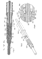
- is a front isometric view of a fiber optic cartridge of the present invention, with the frame shown in phantom lines.
- FIG. 7
- is a sectional side view of the cartridge of FIG. 6.
- FIG. 8
- is an enlarged view of area 8--8 of FIG. 7.
- FIGS. 1 and 2 illustrate a connector 10 which includes a fiber
optic cartridge 12 and ahousing 14 with apassageway 16 that receives the cartridge. The cartridge includes aframe 20 and aterminus 22 that extends through a throughpassage 24 of the frame. Anoptic fiber cable 30 extends through abend limiting sleeve 32 and through abendable coupling 34, and through the terminus to atip 42 of aferrule 40 of the terminus. - FIG. 3 shows that the
terminus 22 includes abody 50 that holds the rear end of theferrule 40, preferably in a press fit, and that has abore 44 with anarrow middle 102 and a wider rear portion that holds the cable. Aspring 52 has a rear end that abuts a largely forwardly-facinginternal shoulder 54 of theframe 20 and that has a front end that abuts an external largely rearwardly-facingshoulder 56 on the terminus body. The terminus body has an enlargedfront portion 60 with a front end forming a largely forwardly-facingshoulder 62 that abuts a largely rearwardly-facing internal shoulder 64 on thehousing 14. FIG. 3 shows the terminus in its most forward position, wherein theentire spring 52 is protected by theframe 20. The body has a narrowrear portion 70 with arear end 72 that is swaged, to form anexternal flange shoulder 73 that is in line with aninternal frame shoulder 74 to limit forward movement of the terminus within theframe 20 and prevent substantial exposure of thespring 52, and to prevent the ferrule from falling out of the frame. - The
frame 20 has anexternal flange 80 near its rear end, which is used in conjunction with aretainer 82 to releasably hold thecartridge 12 in thehousing passageway 16. It is possible to merely form a groove where theflange 80 lies, to provide a shoulder. Theparticular retainer 82 is in the form of a sheet metal clip withtines 86 that abut a largely rearwardly-facing shoulder 90 of the frame. A rear end of the clip abuts a forwardly facing and clip-retaining housingrear shoulder 91. A tool can be inserted into the rear 92 of the housing passageway 16 (by first pulling thecoupling 34 rearward) to expand thetines 86 and withdraw thecartridge 12 from the housing passageway. Such tool does not slide across thespring 52 or against any part of the terminus, so it cannot damage the spring or terminus. As mentioned above, when thecartridge 12 lies outside of the housing, the spring is protected. Since thespring 52 is a permanent part of the cartridge, no clip is required to remove the terminus from the frame of the cartridge. - The cartridge is assembled by pressing the
ferrule 40 rearwardly into thefront portion 60 of the body. Thespring 52 is slid forwardly F against thebody shoulder 56. The terminus, with thespring 52 thereon, is then slid rearwardly R into the front end of thethrough passage 44 of theframe 20. Therear end 72 of the terminus body is swaged to enlarge it so that it can abut theshoulder 74 of the frame to prevent the terminus from moving forwardly from the position shown in FIG. 3. - The
optic fiber cable 30 is prepared by stripping protective material from around the front portion of the glass fiber 100. The cable is inserted forwardly through the bodyrear portion 70 and through abore 102, with the stripped fiber 100 inserted through theferrule 40 until the tip of theferrule tip 42. The fiber tip is polished flush with the ferrule tip. Then, flowable epoxy is flowed into the narrow space between the outside of the cable and the inside of the body to fill this space with epoxy, to bond the cable to the body. Care must be taken to dispense the proper amount of epoxy, to fill most of the body passage without overflowing epoxy rearward of the bodyrear end 72. Such overflow could bond the body to theframe 20 or even to the spring and prevent proper operation of the cartridge. Too little epoxy would risk the possibility that the cable could be pulled out of the cartridge. - It would be desirable if the optic fiber cable could be installed in the body and bonded in place, before the
body 50 was installed in theframe 20. - FIGS. 6 to 8 illustrate a
cartridge 300 that enables the fiberoptic cable 30 to be installed in thebody 302 and to be bonded by epoxy in the body, before the body is installed in aframe 304. This is made possible by constructing the bodyrear portion 310 with arear part 312 that hasfingers 314 withrear ends 316 that are radially deflectable. - The body
rear part 312 has a plurality ofslots 320 extending forwardly into the rear edge of the body to form thefingers 314. As shown in FIG. 8, each finger has a radially (with respect to body axis 322) outwardly extending flange orprojection 324 that forms a rearwardly-facingshoulder 330. Each finger shoulder abuts a forwardly facingshoulder 326 on the frame. - When the terminus is assembled so the
spring 52 andferrule 40 are installed in thebody 302 to form aterminus 328, thefiber optic cable 30 is installed in the terminus bonding agent such as epoxy 340 (FIG. 8) is or has been installed in the space between thecable 30 and the walls of the body bore 342. The terminus is then installed in thepassage 343 in theframe 304. Since the epoxy rear end 345 does not lie within the fingers but only forward of thefingers 314, the fingers will deflect radially inward asbevelled tips 344 of the fingers encounter aninternal flange 346 of the frame. The cable has adeflectable jacket 348 that can be readily depressed by the finger rear ends. The finger rear ends have bevelledinner ends 349 to facilitate movement along the cable jacket. When the fingers snap outward their inside surfaces do not project into the cable jacket. With further rearward movement of the terminus, the finger projections snap radially outward so rearwardly-facing finger shoulders 350 abut forwardly facing flange shoulder 352. The body is then latched in the frame, in that the body can be removed forwardly only by taking special measures to deflect the fingers radially inwardly while moving the body forwardly. - After the
terminus 328 of FIG. 6 has been installed in theframe 304 on theterminus 22 of FIG. 3 has been installed in itsframe 20, the trailing portion of the fiber optic cable is finished. Thebendable coupling 34 is moved forward, thestrength member 110 of the optic fiber cable is wrapped around arear portion 112 of the frame, and a crimp sleeve 114 is crimped around them. - In FIG. 3, the body is formed with an elongated undercut
recess 120 for receiving theclip retainer 82. Thecartridge 12 is installed by merely inserting it forwardly into and through thehousing passageway 16. Forward movement of the frame is limited by the framefront end 130 abutting a correspondinginternal shoulder 132 of the housing. Also, a rear flangefront end 134 abuts a housinginternal shoulder 136 which also limits forward movement of the cartridge within the housing. - FIG. 4 illustrates a modified
housing 14A that is identical to that of FIG. 3, except that the housing has interferingparts 150 on opposite sides of thehousing passageway 16A, that deflect apart to allow the frameexternal flange 80 to pass therethrough, and which have largely forwardly-facingshoulders 152 that then prevent cartridge removal unless theinterference parts 150 are spread apart. A variety of retainers can be used to hold theoptic fiber cartridge 12 in place and allow its removal when necessary. The presence of theflange 80 facilitates operations of such releasably retainers. - The
cartridges ferrule 40 is required to have a predetermined diameter A to fit into a standarddiameter alignment sleeve 160 that is contained in analignment cartridge 162 that fits into arecess 164 at the front end of the housing. The terminusbody front portion 60 must have a somewhat larger diameter than the ferrule to robustly hold the rear end of theferrule 40. The framefront end 166 can be thin and have only a slightly greater diameter than the terminusbody front portion 60. The bodyrear portion 70 has a small diameter, so thespring 52 can readily fit between the inside of theframe front portion 166 and the outside of the bodyrear portion 70. This results in a cartridge of small diameter, with theflange 80 at the rear adding only a small addition diameter. In FIG. 4, the ferrule has a standard outside diameter A of 1.6 mm, thecartridge 12 has an outside diameter B of 3.3 mm (about 190% of A) along most of its length, and theflange 80 has an outside diameter C of 3.9 mm (about 240% of A). Where the housing holds a single terminus, this results in the cartridge being installable in a housing of small size. Where the housing has multiple passageways, the small diameter of each cartridge enables the multiple passageways of such connector to be closely spaced so that a large number of termini can be installed in a connector of small size. The fact that thebody front portion 60 projects partially forward of the framefront end 130, results in a connector of smaller length. - FIG. 5 illustrates a
connector 200 with sixoptic fiber cartridges 12 installed therein. A prior art installation, which included a releasably retention clip that engaged the terminus body and a spring with space for a release tool to fit around or within the spring, might allow only five termini to be placed in a connector of the same diameter. - Thus, the invention provides a fiber optic cartridge that is self-contained, and wherein the fiber optic cable can be installed in the body bore and bonded in place prior to the body being inserted rearwardly into the frame passage and latched in place. The body has a rear part forming a plurality of fingers with free rear ends that have radially outwardly extending projections with forwardly-facing shoulders. The frame has a forwardly-facing shoulder. When the body is slid rearwardly into the frame, the fingers are radially inwardly compressed until their projections spring outward and the shoulders on the projections lie against the forwardly-facing shoulder on the frame to latch the body in the frame. Epoxy or other flowable bonding material is established in the body bore and around the cable, but the mass of bonding material terminates forward of the fingers. The frame forwardly-facing shoulder is preferably formed on an internal flange in the frame passage. The finger outer surfaces up to the projections, are recessed from more forward parts of the fingers.
Claims (3)
- A self-contained fiber optic cartridge (300) which includes a frame (304) having a through passage, a coil spring (52) lying in said passage and having a rear end abutting said frame, a terminus (328) which includes a body (302) that extends through said spring and that has a shoulder (56) that abuts a front end of said spring and that has bore walls that form a through bore, said terminus also including a ferrule (40) at a front end of the body, and including a fiber optic cable (30) that extends through said bore in said body and through said ferrule, wherein:said frame (300) has a rearwardly-facing shoulder (316) lying rearward of said spring;
said body has a rear part with a rear edge and a plurality of slots extending into said rear edge to form a plurality of fingers (314), said fingers having outwardly-projecting flanges at their rear ends that form forwardly-facing shoulders that abut said frame rearwardly-facing shoulder; and
including a quantity of bonding material (340) that bonds said cable (30) to the walls of said body bore (342), said quantity of bonding material having a rear end that lies forward of said fingers, to thereby enable the cable to be bonded in the body bore and thereafter allow the body to be inserted rearward into the frame passage and then cause the body to hold itself against forward movement out of the frame. - The cartridge (300) described in claim 1 wherein:said body (302) has a rear portion with a front part of a first outside diameter, that extends through and rearward of the spring, said body rear portion having a rear part that includes said fingers (314), said rear part having a smaller outside diameter than said first diameter, up to said flanges;said frame passage (342) forms as internal flange (346) with a rear end forming said rearwardly-facing shoulder (326) and with a front end lying rearward of said front part of said body rear portion.
- A method for constructing a fiber optic cartridge (300) to hold an optic fiber cable, comprising:inserting the cable (30) forwardly through a bore in a body (302) of the cartridge, and flowing a bonding material (340) that hardens into said bore and allowing said bonding material to bond to said bore and cable along said bore;inserting a spring (52) rearwardly into a passage of a frame of a terminus of the cartridge until the spring abuts a forwardly facing shoulder of the frame, and inserting said body into the passage;said step of inserting said body rearwardly into said passage includes deflecting each of a plurality of fingers (314) formed at a rear end of the body, radially inwardly while the fingers (314) move at least part of the length of said bore, and then allowing said fingers (314) to spring radially apart so radially outwardly extending flanges at rear ends of said fingers snap behind a forwardly-facing shoulder of said frame to thereafter to prevent the body from falling forwardly out of the frame passage.
Applications Claiming Priority (1)
| Application Number | Priority Date | Filing Date | Title |
|---|---|---|---|
| US11/340,042 US7086785B1 (en) | 2006-01-26 | 2006-01-26 | Optical fiber cartridge with easily installed body |
Publications (2)
| Publication Number | Publication Date |
|---|---|
| EP1813976A1 true EP1813976A1 (en) | 2007-08-01 |
| EP1813976B1 EP1813976B1 (en) | 2008-11-19 |
Family
ID=36758497
Family Applications (1)
| Application Number | Title | Priority Date | Filing Date |
|---|---|---|---|
| EP07100933A Not-in-force EP1813976B1 (en) | 2006-01-26 | 2007-01-22 | Optical fiber cartridge with easily installed body |
Country Status (3)
| Country | Link |
|---|---|
| US (1) | US7086785B1 (en) |
| EP (1) | EP1813976B1 (en) |
| DE (1) | DE602007000248D1 (en) |
Families Citing this family (5)
| Publication number | Priority date | Publication date | Assignee | Title |
|---|---|---|---|---|
| US8046527B2 (en) | 2007-02-22 | 2011-10-25 | Mosaid Technologies Incorporated | Apparatus and method for using a page buffer of a memory device as a temporary cache |
| US8086785B2 (en) | 2007-02-22 | 2011-12-27 | Mosaid Technologies Incorporated | System and method of page buffer operation for memory devices |
| US7785017B2 (en) * | 2007-09-27 | 2010-08-31 | Corning Cable Systems Llc | Strain-relief assemblies and methods for a field-installable fiber optic connector |
| US20100246203A1 (en) * | 2009-03-27 | 2010-09-30 | North American Lighting, Inc. | System and method for exterior lighting of vehicles |
| CN102955205A (en) * | 2011-08-29 | 2013-03-06 | 鸿富锦精密工业(深圳)有限公司 | Optical fiber connector |
Citations (3)
| Publication number | Priority date | Publication date | Assignee | Title |
|---|---|---|---|---|
| US6019520A (en) * | 1997-12-17 | 2000-02-01 | Uconn Technology Inc. | Pre-assembled optical fiber connector |
| US6254283B1 (en) * | 2000-02-22 | 2001-07-03 | Itt Manufacturing Enterprises, Inc. | Terminus body retention |
| US6883974B2 (en) * | 2003-02-21 | 2005-04-26 | Itt Manufacturing Enterprises, Inc. | Optic fiber connector with spring in a self-contained cartridge |
Family Cites Families (2)
| Publication number | Priority date | Publication date | Assignee | Title |
|---|---|---|---|---|
| US5796898A (en) * | 1996-02-28 | 1998-08-18 | Fiberon, Inc. | Modular optical fiber connector |
| US6655851B1 (en) * | 2002-05-22 | 2003-12-02 | Fiberon Technolgies, Inc. | Optical fiber connector |
-
2006
- 2006-01-26 US US11/340,042 patent/US7086785B1/en not_active Expired - Lifetime
-
2007
- 2007-01-22 DE DE602007000248T patent/DE602007000248D1/en active Active
- 2007-01-22 EP EP07100933A patent/EP1813976B1/en not_active Not-in-force
Patent Citations (3)
| Publication number | Priority date | Publication date | Assignee | Title |
|---|---|---|---|---|
| US6019520A (en) * | 1997-12-17 | 2000-02-01 | Uconn Technology Inc. | Pre-assembled optical fiber connector |
| US6254283B1 (en) * | 2000-02-22 | 2001-07-03 | Itt Manufacturing Enterprises, Inc. | Terminus body retention |
| US6883974B2 (en) * | 2003-02-21 | 2005-04-26 | Itt Manufacturing Enterprises, Inc. | Optic fiber connector with spring in a self-contained cartridge |
Also Published As
| Publication number | Publication date |
|---|---|
| US7086785B1 (en) | 2006-08-08 |
| EP1813976B1 (en) | 2008-11-19 |
| DE602007000248D1 (en) | 2009-01-02 |
Similar Documents
| Publication | Publication Date | Title |
|---|---|---|
| US11506848B2 (en) | Mini duplex connector with push-pull polarity mechanism and carrier using rail receiving portions | |
| US6883974B2 (en) | Optic fiber connector with spring in a self-contained cartridge | |
| CN103576251B (en) | Optical connector and method of assembling same | |
| CN101299086B (en) | Optical fibre connector and assembly method thereof | |
| US6254283B1 (en) | Terminus body retention | |
| US20070193025A1 (en) | Ferrule assembly and methods thereof | |
| US6497516B1 (en) | Guide pin for optical fiber connectors and optical fiber connector plug | |
| JP2005114860A (en) | Ferrule for optical connector and method of assembling optical connector | |
| US8292514B2 (en) | Optical connecting member and method of fitting the same | |
| MXPA06010746A (en) | Field installable optical fiber connector. | |
| EP1813976B1 (en) | Optical fiber cartridge with easily installed body | |
| JP2006276566A (en) | Optical connector | |
| KR100713430B1 (en) | Optical connector plug, manufacturing method and assembly tool | |
| US6732426B2 (en) | Fiber extraction tool | |
| US5768455A (en) | Fiber optic connector | |
| JP5325244B2 (en) | Boots, optical connectors and jigs | |
| US12345928B2 (en) | End part structure for optical connectors | |
| US9417400B2 (en) | Short optical connector for cables containing a bend insensitive fiber | |
| JP5619498B2 (en) | Optical connector assembling jig and optical connector assembling method | |
| CN114730043A (en) | Optical fiber connector, subassembly and method of manufacture | |
| JP5108738B2 (en) | Optical connector and optical connector assembling method | |
| JP2010134102A (en) | Method for assembling optical connector and optical connector | |
| JP5346855B2 (en) | Optical connector | |
| JP2003202456A (en) | Releasable terminal holding device | |
| JP4117797B2 (en) | Optical connector assembly and manufacturing method thereof |
Legal Events
| Date | Code | Title | Description |
|---|---|---|---|
| PUAI | Public reference made under article 153(3) epc to a published international application that has entered the european phase |
Free format text: ORIGINAL CODE: 0009012 |
|
| AK | Designated contracting states |
Kind code of ref document: A1 Designated state(s): AT BE BG CH CY CZ DE DK EE ES FI FR GB GR HU IE IS IT LI LT LU LV MC NL PL PT RO SE SI SK TR |
|
| AX | Request for extension of the european patent |
Extension state: AL BA HR MK YU |
|
| 17P | Request for examination filed |
Effective date: 20080201 |
|
| AKX | Designation fees paid |
Designated state(s): DE FR GB IT |
|
| GRAP | Despatch of communication of intention to grant a patent |
Free format text: ORIGINAL CODE: EPIDOSNIGR1 |
|
| RIN1 | Information on inventor provided before grant (corrected) |
Inventor name: BATES III, CHARLES LINSDAY |
|
| GRAS | Grant fee paid |
Free format text: ORIGINAL CODE: EPIDOSNIGR3 |
|
| GRAA | (expected) grant |
Free format text: ORIGINAL CODE: 0009210 |
|
| AK | Designated contracting states |
Kind code of ref document: B1 Designated state(s): DE FR GB IT |
|
| REG | Reference to a national code |
Ref country code: GB Ref legal event code: FG4D |
|
| REF | Corresponds to: |
Ref document number: 602007000248 Country of ref document: DE Date of ref document: 20090102 Kind code of ref document: P |
|
| PLBE | No opposition filed within time limit |
Free format text: ORIGINAL CODE: 0009261 |
|
| STAA | Information on the status of an ep patent application or granted ep patent |
Free format text: STATUS: NO OPPOSITION FILED WITHIN TIME LIMIT |
|
| 26N | No opposition filed |
Effective date: 20090820 |
|
| PGRI | Patent reinstated in contracting state [announced from national office to epo] |
Ref country code: IT Effective date: 20110501 |
|
| REG | Reference to a national code |
Ref country code: FR Ref legal event code: PLFP Year of fee payment: 10 |
|
| REG | Reference to a national code |
Ref country code: FR Ref legal event code: PLFP Year of fee payment: 11 |
|
| PGFP | Annual fee paid to national office [announced via postgrant information from national office to epo] |
Ref country code: DE Payment date: 20170125 Year of fee payment: 11 Ref country code: FR Payment date: 20170125 Year of fee payment: 11 |
|
| PGFP | Annual fee paid to national office [announced via postgrant information from national office to epo] |
Ref country code: GB Payment date: 20170127 Year of fee payment: 11 |
|
| PGFP | Annual fee paid to national office [announced via postgrant information from national office to epo] |
Ref country code: IT Payment date: 20170124 Year of fee payment: 11 |
|
| REG | Reference to a national code |
Ref country code: DE Ref legal event code: R119 Ref document number: 602007000248 Country of ref document: DE |
|
| GBPC | Gb: european patent ceased through non-payment of renewal fee |
Effective date: 20180122 |
|
| PG25 | Lapsed in a contracting state [announced via postgrant information from national office to epo] |
Ref country code: FR Free format text: LAPSE BECAUSE OF NON-PAYMENT OF DUE FEES Effective date: 20180131 Ref country code: DE Free format text: LAPSE BECAUSE OF NON-PAYMENT OF DUE FEES Effective date: 20180801 |
|
| REG | Reference to a national code |
Ref country code: FR Ref legal event code: ST Effective date: 20180928 |
|
| PG25 | Lapsed in a contracting state [announced via postgrant information from national office to epo] |
Ref country code: GB Free format text: LAPSE BECAUSE OF NON-PAYMENT OF DUE FEES Effective date: 20180122 |
|
| PG25 | Lapsed in a contracting state [announced via postgrant information from national office to epo] |
Ref country code: IT Free format text: LAPSE BECAUSE OF NON-PAYMENT OF DUE FEES Effective date: 20180122 |