EP1813973A1 - Optical fiber - Google Patents
Optical fiber Download PDFInfo
- Publication number
- EP1813973A1 EP1813973A1 EP05795856A EP05795856A EP1813973A1 EP 1813973 A1 EP1813973 A1 EP 1813973A1 EP 05795856 A EP05795856 A EP 05795856A EP 05795856 A EP05795856 A EP 05795856A EP 1813973 A1 EP1813973 A1 EP 1813973A1
- Authority
- EP
- European Patent Office
- Prior art keywords
- optical fiber
- refractive index
- core portion
- range
- falls
- Prior art date
- Legal status (The legal status is an assumption and is not a legal conclusion. Google has not performed a legal analysis and makes no representation as to the accuracy of the status listed.)
- Withdrawn
Links
- 239000013307 optical fiber Substances 0.000 title claims abstract description 103
- UFHFLCQGNIYNRP-UHFFFAOYSA-N Hydrogen Chemical compound [H][H] UFHFLCQGNIYNRP-UHFFFAOYSA-N 0.000 claims abstract description 11
- 229910052739 hydrogen Inorganic materials 0.000 claims abstract description 11
- 239000001257 hydrogen Substances 0.000 claims abstract description 11
- 230000032683 aging Effects 0.000 claims abstract description 9
- 239000010453 quartz Substances 0.000 claims abstract description 3
- VYPSYNLAJGMNEJ-UHFFFAOYSA-N silicon dioxide Inorganic materials O=[Si]=O VYPSYNLAJGMNEJ-UHFFFAOYSA-N 0.000 claims abstract description 3
- 238000000034 method Methods 0.000 description 19
- 230000003287 optical effect Effects 0.000 description 10
- 230000000694 effects Effects 0.000 description 8
- 239000002019 doping agent Substances 0.000 description 7
- 238000004519 manufacturing process Methods 0.000 description 7
- 230000001965 increasing effect Effects 0.000 description 5
- 238000001228 spectrum Methods 0.000 description 4
- YZCKVEUIGOORGS-OUBTZVSYSA-N Deuterium Chemical compound [2H] YZCKVEUIGOORGS-OUBTZVSYSA-N 0.000 description 3
- 230000005535 acoustic phonon Effects 0.000 description 3
- 229910052805 deuterium Inorganic materials 0.000 description 3
- 229910003910 SiCl4 Inorganic materials 0.000 description 2
- 238000010521 absorption reaction Methods 0.000 description 2
- 230000005540 biological transmission Effects 0.000 description 2
- 230000008021 deposition Effects 0.000 description 2
- 230000002708 enhancing effect Effects 0.000 description 2
- 125000002887 hydroxy group Chemical group [H]O* 0.000 description 2
- 239000000463 material Substances 0.000 description 2
- FDNAPBUWERUEDA-UHFFFAOYSA-N silicon tetrachloride Chemical compound Cl[Si](Cl)(Cl)Cl FDNAPBUWERUEDA-UHFFFAOYSA-N 0.000 description 2
- 229910052691 Erbium Inorganic materials 0.000 description 1
- PXGOKWXKJXAPGV-UHFFFAOYSA-N Fluorine Chemical compound FF PXGOKWXKJXAPGV-UHFFFAOYSA-N 0.000 description 1
- 229910006113 GeCl4 Inorganic materials 0.000 description 1
- QVGXLLKOCUKJST-UHFFFAOYSA-N atomic oxygen Chemical compound [O] QVGXLLKOCUKJST-UHFFFAOYSA-N 0.000 description 1
- 238000004891 communication Methods 0.000 description 1
- 230000007547 defect Effects 0.000 description 1
- 230000000593 degrading effect Effects 0.000 description 1
- 230000018109 developmental process Effects 0.000 description 1
- UYAHIZSMUZPPFV-UHFFFAOYSA-N erbium Chemical compound [Er] UYAHIZSMUZPPFV-UHFFFAOYSA-N 0.000 description 1
- 239000000835 fiber Substances 0.000 description 1
- 229910052731 fluorine Inorganic materials 0.000 description 1
- 239000011737 fluorine Substances 0.000 description 1
- 239000007789 gas Substances 0.000 description 1
- 229910052732 germanium Inorganic materials 0.000 description 1
- GNPVGFCGXDBREM-UHFFFAOYSA-N germanium atom Chemical compound [Ge] GNPVGFCGXDBREM-UHFFFAOYSA-N 0.000 description 1
- 229910052760 oxygen Inorganic materials 0.000 description 1
- 239000001301 oxygen Substances 0.000 description 1
- 230000000737 periodic effect Effects 0.000 description 1
- 230000008054 signal transmission Effects 0.000 description 1
- 230000003595 spectral effect Effects 0.000 description 1
- IEXRMSFAVATTJX-UHFFFAOYSA-N tetrachlorogermane Chemical compound Cl[Ge](Cl)(Cl)Cl IEXRMSFAVATTJX-UHFFFAOYSA-N 0.000 description 1
- 238000007740 vapor deposition Methods 0.000 description 1
- 239000012808 vapor phase Substances 0.000 description 1
Images


Classifications
-
- G—PHYSICS
- G02—OPTICS
- G02B—OPTICAL ELEMENTS, SYSTEMS OR APPARATUS
- G02B6/00—Light guides; Structural details of arrangements comprising light guides and other optical elements, e.g. couplings
- G02B6/02—Optical fibres with cladding with or without a coating
- G02B6/036—Optical fibres with cladding with or without a coating core or cladding comprising multiple layers
- G02B6/03605—Highest refractive index not on central axis
- G02B6/03611—Highest index adjacent to central axis region, e.g. annular core, coaxial ring, centreline depression affecting waveguiding
-
- G—PHYSICS
- G02—OPTICS
- G02B—OPTICAL ELEMENTS, SYSTEMS OR APPARATUS
- G02B6/00—Light guides; Structural details of arrangements comprising light guides and other optical elements, e.g. couplings
- G02B6/02—Optical fibres with cladding with or without a coating
- G02B6/028—Optical fibres with cladding with or without a coating with core or cladding having graded refractive index
-
- G—PHYSICS
- G02—OPTICS
- G02B—OPTICAL ELEMENTS, SYSTEMS OR APPARATUS
- G02B6/00—Light guides; Structural details of arrangements comprising light guides and other optical elements, e.g. couplings
- G02B6/02—Optical fibres with cladding with or without a coating
- G02B6/02004—Optical fibres with cladding with or without a coating characterised by the core effective area or mode field radius
-
- G—PHYSICS
- G02—OPTICS
- G02B—OPTICAL ELEMENTS, SYSTEMS OR APPARATUS
- G02B6/00—Light guides; Structural details of arrangements comprising light guides and other optical elements, e.g. couplings
- G02B6/02—Optical fibres with cladding with or without a coating
- G02B6/02004—Optical fibres with cladding with or without a coating characterised by the core effective area or mode field radius
- G02B6/02009—Large effective area or mode field radius, e.g. to reduce nonlinear effects in single mode fibres
- G02B6/02014—Effective area greater than 60 square microns in the C band, i.e. 1530-1565 nm
- G02B6/02019—Effective area greater than 90 square microns in the C band, i.e. 1530-1565 nm
-
- G—PHYSICS
- G02—OPTICS
- G02B—OPTICAL ELEMENTS, SYSTEMS OR APPARATUS
- G02B6/00—Light guides; Structural details of arrangements comprising light guides and other optical elements, e.g. couplings
- G02B6/02—Optical fibres with cladding with or without a coating
- G02B6/028—Optical fibres with cladding with or without a coating with core or cladding having graded refractive index
- G02B6/0281—Graded index region forming part of the central core segment, e.g. alpha profile, triangular, trapezoidal core
Definitions
- the present invention relates to an optical fiber for use in the field of optical communication applications which input, into the optical fiber, signal light having a relatively high optical energy.
- signals are transmitted via a single optical fiber to a location near subscribers, and split at the location appropriately in accordance with the number of the subscribers.
- PON passive optical network
- EDFAs erbium doped fiber amplifiers
- SBS stimulated Brillouin scattering
- the SBS occurs in the following manner.
- a periodic density distribution is formed within the optical fiber due to acoustic phonons, and functions as gratings, to scatter the signal light. Since the acoustic phonons also move, the scattered light has a frequency slightly lower than the original signal light because of the Doppler effect. The interference between the scattered light and signal light further excites the acoustic phonons, thereby increasing the scattering intensity.
- the scattering has little influence on the signal light.
- the intensity of the signal light exceeds the threshold value, the scattering intensity radically increases. Once the intensity of the signal light reaches a certain level, the increase in the intensity of the signal light input into the optical fiber only raises the scattered light, and does not enhance the intensity of the actually transmitted signal. On the contrary, such an increase raises noise, thereby degrading the signal.
- Patent Document 2 discloses a method to raise the threshold value to cause the SBS by varying the density of the dopant such as fluorine in the longitudinal direction of the optical fiber in the step of forming part of the core and clad portions when a preform for an optical fiber is manufactured by using a two-step method.
- Patent Document 3 discloses a similar method of varying the dopant density in the longitudinal direction.
- Patent Document 4 discloses a method to simultaneously vary both the diameter of the core and the relative refractive index difference in the longitudinal direction. According to all of the methods mentioned above, the values of one or more parameters are varied in the longitudinal direction of the optical fiber.
- Patent Document 5 discloses the following method.
- a plurality of annular regions are formed in the vicinity of the boundary between the core and clad portions.
- the annular regions each have a small thickness, and are uniform in the longitudinal direction.
- a dopant having a different coefficient of thermal expansion (CTE) and a different viscosity is doped.
- the annular regions are adjusted so as not to affect the transmission characteristics which are determined by the refractive index distribution. In this manner, a distortion distribution is formed in the radial direction in the optical fiber, in order to reduce the SBS.
- CTE coefficient of thermal expansion
- Non-Patent Document 1 " Optical Fiber Telecommunications IIIA", Academic Press, page 200
- Patent Document 1 Japanese Patent No. 2584151
- Patent Document 2 Japanese Patent No. 2753426
- Patent Document 3 Unexamined Japanese Patent Application Publication No. H09-301738
- Patent Document 4 Unexamined Japanese Patent Application Publication No. H10-96828
- Patent Document 5 United States Patent No. 6,542,683
- the method in which thin annular regions are formed so as to be arranged in the radial direction of the optical fiber by using a plurality of dopants is very difficult to be practiced because the dopants disperse in the radial direction during the manufacturing process of the optical fiber.
- an optical fiber manufactured by using this method suffers from a larger loss than a normal optical fiber, and has a small value for L e . Therefore, this method has difficulties in achieving desired effects.
- the optical fiber manufactured by means of this method poses another drawback that an even higher optical energy needs to be input.
- An advantage of some embodiments of the present invention is to provide an optical fiber which can be manufactured at low costs, has a higher threshold value to cause the SBS, and enables signal light having a high energy to be input.
- An optical fiber relating to the present invention includes a clad portion and a core portion surrounded by the clad portion.
- the clad portion is formed by substantially pure quartz, and the core portion has a higher refractive index than the clad portion.
- the optical fiber relating to the present invention is characterized in that a relative retractive index difference of a center of the core portion falls within a range from 0.15 % to 0.30 %, and a maximum relative refractive index difference of the core portion falls within a range from 0.4 % to 0.6 %. Having such a unique refractive index distribution, the optical fiber achieves a high threshold value to cause the SBS.
- the optical fiber is difficult to be manufactured.
- the relative refractive index difference of the center of the core portion is higher than 0.30 %, or when the maximum relative refractive index difference of the core portion is lower than 0.4 %, only a small rise is achieved for the threshold value to cause the SBS. Therefore, the effects achieved are insignificant.
- the optical fiber can satisfy the characteristics defined by International Telecommunication Union Telecommunication Standardization Section (ITU-T) G 652, with it being possible to achieve a high threshold value to cause the SBS. Therefore, this configuration is desirable.
- ITU-T International Telecommunication Union Telecommunication Standardization Section
- the optical fiber can achieve a high threshold value to cause the SBS.
- a mode field diameter of the optical fiber falls within a range from 8.6 ⁇ m to 9.5 ⁇ m at 1310 nm, and a cable cutoff wavelength of the optical fiber is equal to or lower than 1260 nm. Furthermore, after the optical fiber is subjected to hydrogen aging, a loss of the optical fiber is preferably equal to or lower than 0.4 dB/km at 1383 nm. Having this configuration, the optical fiber provided can satisfy the standards defined by ITU-T G 652, and achieves a high threshold value to cause the SBS.
- the present invention enables an optical fiber having a high threshold value to cause the SBS to be manufactured at low costs. Furthermore, the optical fiber has approximately the same mode field diameter (MFD) as a normal single mode optical fiber, and therefore suffers from only a small connection loss when connected to a normal single mode optical fiber.
- MFD mode field diameter
- the loss spectrum of the optical fiber relating to the present invention is substantially the same as that of a normal low-moisture single mode optical fiber that satisfies the characteristics defined by ITU-T G652C, even after a hydrogen aging test is conducted on the optical fiber.
- the threshold value (mW) to cause the SBS is proportional to the value of A e .
- the SBS threshold value can be raised accordingly.
- the SBS threshold value may be raised, but the increase in loss needs to be compensated for by inputting a higher optical energy. As a consequence, the optical fiber can not satisfy the requirements relating to signal transmission.
- a desirable optical fiber has such a refractive index profile that the refractive index increases from the center of the core portion towards the external surface.
- the relative refractive index difference of the center of the core portion falls within the range of 0.15 % to 0.30 %
- the maximum relative refractive index difference of the core portion falls within the range of 0.4 % to 0.6 %. More particularly, it has been found even easier for the optical fiber to satisfy the standards defined by ITU-T G 652 when the refractive index distribution of the core portion is adjusted so that the average value calculated based on the maximum and minimum values of the relative refractive index difference of the core portion falls within the range of 0.30 % to 0.40 %.
- the optical fiber having the above-described features may be used in an application utilizing many signal wavelength bands due to wavelength division multiplexing (WDM).
- the signal wavelength bands utilized may include a wavelength band in the vicinity of the wavelength of 1383 nm at which the absorption loss caused by OH groups peaks.
- the loss at the wavelength band including, for example, the wavelength of 1550 nm is increased. Such an increase may resultantly require a higher optical energy to be input into the optical fiber.
- the optical fiber can preferably maintain a low loss of equal to or lower than 0.40 dB/km at the wavelength of 1383 nm even after a hydrogen aging test is conducted on the optical fiber to simulate an increase in loss during the lifetime of the optical fiber.
- An exemplary method to prevent the optical fiber from being affected by hydrogen aging is as follows.
- the optical fiber is exposed to an atmosphere containing therein deuterium for a predetermined period of time after the drawing step.
- the exposure to deuterium can inactivate in advance active defects which may cause an increase in loss due to hydrogen.
- a core rod including therein a core and a clad is manufactured by means of the vapor phase axial deposition (VAD) method.
- the manufactured core rod has the refractive index profile shown in Fig. 1.
- the refractive index distribution of the core rod has a unique profile in which the refractive index increases in a substantially continuous manner from the vicinity of the center towards the external surface and symmetrical peaks are formed at positions substantially corresponding to the external periphery of the core. Outside the peaks in the refractive index profile, the refractive index radically drops.
- the portions in the refractive index profile outside the peaks correspond to the clad
- the core of the manufactured optical fiber has an effective diameter of 8.3 ⁇ m.
- the core rod is manufactured by performing deposition with the use of one burner for the core and two burners for the clad.
- the refractive index profile characterizing the present invention is obtained by adjusting the conditions relating to the gases used by the burners and the conditions relating to the setting of the burners.
- the burner for the core is supplied with, as a gaseous material, SiCl 4 and, as a dopant, GeCl 4 .
- the burners for the clad are supplied with SiCl 4 along with oxygen and hydrogen which are to create a flame.
- a necessary clad is additionally formed by means of the outside vapor deposition (OVD) method. In this manner, a preform for an optical fiber is manufactured.
- the relative refractive index difference of the center of the core of the preform is 0.23 %
- the maximum e relative refractive index difference of the core is 0.5 %.
- an optical fiber is obtained.
- the obtained optical fiber has an MFD of 9.3 ⁇ m and a cable cutoff wavelength of 1220 nm.
- the optical fiber is subjected to a hydrogen aging test.
- the loss spectral characteristics of the optical fiber is shown in Fig. 2, and substantially the same as those of a normal low-moisture single mode optical fiber that satisfies the standards defined by ITU-T G 652C, even after the hydrogen aging test.
- the value of A e of the optical fiber is 90 ⁇ m 2 , and fairly larger than the value of A e (82 ⁇ m 2 ) of a single mode optical fiber which has a rectangular profile and the same characteristics as the optical fiber.
- the SBS threshold value of the optical fiber at the wavelength of 1550 nm is higher by approximately 3 dB. The reason for this increase may be explained as follows. In addition to the increase achieved by the increase in the value of A e , the density of germanium, which is included in the dopant to form the refractive index distribution of the core portion, is significantly varied in the radial direction, and this secondarily achieves effects of broadening the spectrum of the scattered light, thereby contributing to the increase in the SBS threshold value.
- the MFD of this optical fiber is similar to the MFD of a normal single mode optical fiber. Therefore, even when this optical fiber is connected to a normal single mode optical fiber, the connection loss is kept low, similarly to a case where normal single mode optical fibers are connected to each other.
- Fig. 4 shows a refractive index distribution according to which the core portion has the maximum refractive index in a position which is not positioned at the outmost part of the core portion.
- the manufactured optical fiber also realizes the effects of enhancing the SBS threshold value.
- an optical fiber, which is manufactured by using the core rod having a refractive index distribution in which the refractive index peaks at a plurality of wavelengths can also realize the effects of enhancing the SBS threshold value. Note that, however, it is more advantageous in improving the SBS threshold value that the high refractive index part and the low refractive index part are sufficiently distant from each other.
- the present invention makes it possible to manufacture an optical fiber having a high threshold value to cause the SBS at low costs, and to achieve a further longer distance between relay points for transmission.
Landscapes
- Physics & Mathematics (AREA)
- General Physics & Mathematics (AREA)
- Optics & Photonics (AREA)
- Manufacture, Treatment Of Glass Fibers (AREA)
- Optical Fibers, Optical Fiber Cores, And Optical Fiber Bundles (AREA)
- Glass Compositions (AREA)
Abstract
Description
- The present invention relates to an optical fiber for use in the field of optical communication applications which input, into the optical fiber, signal light having a relatively high optical energy.
- Here, the contents of the following patent applications are incorporated herein by reference, if applicable.
Japanese Patent Application No. 2004-316796 filed on October 29, 2004
Japanese Patent Application No. 2005-048792 filed on February 24, 2005 - According to applications such as passive optical network (PON) systems, signals are transmitted via a single optical fiber to a location near subscribers, and split at the location appropriately in accordance with the number of the subscribers. When this technique is utilized, the further the splitting location is positioned from the base station, or the larger the number of the subscribers is, the higher optical energy the base station needs to input into the optical fiber.
- Recent development of amplifiers such as erbium doped fiber amplifiers (EDFAs) has increasingly enabled high optical energy to be input into the optical fiber. Generally speaking, however, when signal light having a high energy is input into an optical fiber, a phenomenon called stimulated Brillouin scattering (SBS) occurs. This phenomenon reduces the amount of optical energy that is actually transmitted. As mentioned, for example, in the non-Patent Document 1, a threshold value (mW) of the optical energy to cause the SBS is proportional to the effective cross-section (Ae) of the optical fiber, and inversely proportional to the Brilliouin gain coefficient gB and effective interacting length (Le).
- Here, the SBS occurs in the following manner. A periodic density distribution is formed within the optical fiber due to acoustic phonons, and functions as gratings, to scatter the signal light. Since the acoustic phonons also move, the scattered light has a frequency slightly lower than the original signal light because of the Doppler effect. The interference between the scattered light and signal light further excites the acoustic phonons, thereby increasing the scattering intensity.
- When the signal light has an intensity equal to or lower than the threshold value to cause the SBS, the scattering has little influence on the signal light. However, when the intensity of the signal light exceeds the threshold value, the scattering intensity radically increases. Once the intensity of the signal light reaches a certain level, the increase in the intensity of the signal light input into the optical fiber only raises the scattered light, and does not enhance the intensity of the actually transmitted signal. On the contrary, such an increase raises noise, thereby degrading the signal.
- In view of the above, a variety of methods have been proposed to raise the threshold value to cause the SBS.
Here, the spectrum of the scattered light differs depending on the composition of the materials and distortion of the optical fiber used. It has been found that the broader the spectrum of the scattered light is, the higher the threshold value to cause the SBS becomes. According to Patent Document 1, for example, a method is disclosed to raise the threshold value to cause the SBS by varying the diameter of the core, the refractive index and distortion in the longitudinal direction of the optical fiber. Patent Document 2 discloses a method to raise the threshold value to cause the SBS by varying the density of the dopant such as fluorine in the longitudinal direction of the optical fiber in the step of forming part of the core and clad portions when a preform for an optical fiber is manufactured by using a two-step method. Patent Document 3 discloses a similar method of varying the dopant density in the longitudinal direction. Patent Document 4 discloses a method to simultaneously vary both the diameter of the core and the relative refractive index difference in the longitudinal direction. According to all of the methods mentioned above, the values of one or more parameters are varied in the longitudinal direction of the optical fiber. - In addition to the above-mentioned methods, Patent Document 5 discloses the following method. A plurality of annular regions are formed in the vicinity of the boundary between the core and clad portions. The annular regions each have a small thickness, and are uniform in the longitudinal direction. In each of the annular regions, a dopant having a different coefficient of thermal expansion (CTE) and a different viscosity is doped. The annular regions are adjusted so as not to affect the transmission characteristics which are determined by the refractive index distribution. In this manner, a distortion distribution is formed in the radial direction in the optical fiber, in order to reduce the SBS.
- Non-Patent Document 1: "Optical Fiber Telecommunications IIIA", Academic Press, page 200
Patent Document 1:Japanese Patent No. 2584151
Patent Document 2:Japanese Patent No. 2753426
Patent Document 3: UnexaminedJapanese Patent Application Publication No. H09-301738
Patent Document 4: Unexamined Japanese Patent Application Publication No.H10-96828
Patent Document 5:United States Patent No. 6,542,683 - When a method of varying one or more characteristic parameters of an optical fiber in the longitudinal direction of the optical fiber is used, remarkable effects can be obtained by varying the parameters in short intervals of equal to or shorter than approximately 1 km. However, low-cost methods of manufacturing optical fibers based on large preforms have difficulties in varying the parameters in such short intervals, considering that the drawing rate is as high as 1 km/min or higher and, when a large preform is used, a preform having a length of as short as approximately 1.5 mm to 5 mm is sufficient to manufacture an optical fiber of 1 km by drawing.
- On the other hand, the method in which thin annular regions are formed so as to be arranged in the radial direction of the optical fiber by using a plurality of dopants is very difficult to be practiced because the dopants disperse in the radial direction during the manufacturing process of the optical fiber. In addition, an optical fiber manufactured by using this method suffers from a larger loss than a normal optical fiber, and has a small value for Le. Therefore, this method has difficulties in achieving desired effects. The optical fiber manufactured by means of this method poses another drawback that an even higher optical energy needs to be input.
- An advantage of some embodiments of the present invention is to provide an optical fiber which can be manufactured at low costs, has a higher threshold value to cause the SBS, and enables signal light having a high energy to be input.
- An optical fiber relating to the present invention includes a clad portion and a core portion surrounded by the clad portion. Here, the clad portion is formed by substantially pure quartz, and the core portion has a higher refractive index than the clad portion. The optical fiber relating to the present invention is characterized in that a relative retractive index difference of a center of the core portion falls within a range from 0.15 % to 0.30 %, and a maximum relative refractive index difference of the core portion falls within a range from 0.4 % to 0.6 %. Having such a unique refractive index distribution, the optical fiber achieves a high threshold value to cause the SBS.
- It should be noted that when the relative refractive index difference of the center of the core portion is lower than 0.15 %, or when the maximum relative refractive index difference of the core portion is higher than 0.6 %, the optical fiber is difficult to be manufactured. When the relative refractive index difference of the center of the core portion is higher than 0.30 %, or when the maximum relative refractive index difference of the core portion is lower than 0.4 %, only a small rise is achieved for the threshold value to cause the SBS. Therefore, the effects achieved are insignificant.
- When an average relative refractive index difference of the core portion falls within a range from 0.30 % to 0.40 %, the optical fiber can satisfy the characteristics defined by International Telecommunication Union Telecommunication Standardization Section (ITU-T) G 652, with it being possible to achieve a high threshold value to cause the SBS. Therefore, this configuration is desirable.
- It is preferable that, in the core portion of the optical fiber, a part having a high refractive index and a part having a low refractive index are sufficiently distant from each other. With this configuration, the optical fiber can achieve a high threshold value to cause the SBS.
- According to the present invention, a mode field diameter of the optical fiber falls within a range from 8.6 µm to 9.5 µm at 1310 nm, and a cable cutoff wavelength of the optical fiber is equal to or lower than 1260 nm. Furthermore, after the optical fiber is subjected to hydrogen aging, a loss of the optical fiber is preferably equal to or lower than 0.4 dB/km at 1383 nm. Having this configuration, the optical fiber provided can satisfy the standards defined by ITU-T G 652, and achieves a high threshold value to cause the SBS.
- The present invention enables an optical fiber having a high threshold value to cause the SBS to be manufactured at low costs. Furthermore, the optical fiber has approximately the same mode field diameter (MFD) as a normal single mode optical fiber, and therefore suffers from only a small connection loss when connected to a normal single mode optical fiber. Here, the loss spectrum of the optical fiber relating to the present invention is substantially the same as that of a normal low-moisture single mode optical fiber that satisfies the characteristics defined by ITU-T G652C, even after a hydrogen aging test is conducted on the optical fiber.
-
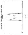
- Fig. 1 is a graph showing a refractive index distribution, in the radial direction, of a core rod used to manufacture an optical fiber relating to a first embodiment of the present invention.
- Fig. 2 is a graph showing a loss of the optical fiber relating to the first embodiment, which is observed after the optical fiber is subjected to hydrogen aging.
- Fig. 3 is a graph showing a refractive index distribution, in the radial direction, of a core rod used to manufacture a conventional optical fiber.
- Fig. 4 is a graph showing a different refractive index distribution, in the radial direction, of another core rod which also can be used to manufacture the optical fiber relating to the first embodiment of the present invention.
- As mentioned earlier, the threshold value (mW) to cause the SBS is proportional to the value of Ae. By simply increasing the value of Ae, the SBS threshold value can be raised accordingly. However, when the value of Ae is increased for a signal mode optical fiber having a normal rectangular profile for the refractive index distribution, for example, the mode field diameter (MFD) increases. Therefore, due to MFD mismatch, the optical fiber suffers from a larger loss at a point where the optical fiber is connected to a different optical fiber. For this reason, the SBS threshold value may be raised, but the increase in loss needs to be compensated for by inputting a higher optical energy. As a consequence, the optical fiber can not satisfy the requirements relating to signal transmission.
- To solve this problem, many efforts have been made. As a result of such efforts, it has been found that, when the following shape (hereinafter referred to as the refractive index profile) is obtained for the refractive index distribution, the value of Ae can be independently increased with it being possible to maintain the parameters such as the MFD and cutoff wavelength at values complying with the ITU-T G652, which is an international standard for a normal single mode optical fiber.
Specifically speaking, a desirable optical fiber has such a refractive index profile that the refractive index increases from the center of the core portion towards the external surface. Here, the relative refractive index difference of the center of the core portion falls within the range of 0.15 % to 0.30 %, and the maximum relative refractive index difference of the core portion falls within the range of 0.4 % to 0.6 %. More particularly, it has been found even easier for the optical fiber to satisfy the standards defined by ITU-T G 652 when the refractive index distribution of the core portion is adjusted so that the average value calculated based on the maximum and minimum values of the relative refractive index difference of the core portion falls within the range of 0.30 % to 0.40 %. - The optical fiber having the above-described features may be used in an application utilizing many signal wavelength bands due to wavelength division multiplexing (WDM). Here, the signal wavelength bands utilized may include a wavelength band in the vicinity of the wavelength of 1383 nm at which the absorption loss caused by OH groups peaks. When a large absorption loss is caused by the OH groups at the peak wavelength, the loss at the wavelength band including, for example, the wavelength of 1550 nm is increased. Such an increase may resultantly require a higher optical energy to be input into the optical fiber. Therefore, taking into consideration that the optical fiber is used for the above use, the optical fiber can preferably maintain a low loss of equal to or lower than 0.40 dB/km at the wavelength of 1383 nm even after a hydrogen aging test is conducted on the optical fiber to simulate an increase in loss during the lifetime of the optical fiber.
- An exemplary method to prevent the optical fiber from being affected by hydrogen aging is as follows. The optical fiber is exposed to an atmosphere containing therein deuterium for a predetermined period of time after the drawing step. The exposure to deuterium can inactivate in advance active defects which may cause an increase in loss due to hydrogen.
- In the following, the present invention is described in more detail based on an exemplary embodiment and a comparison example. However, the present invention is not limited to the following examples, and can provide a variety of different embodiments.
- A core rod including therein a core and a clad is manufactured by means of the vapor phase axial deposition (VAD) method. The manufactured core rod has the refractive index profile shown in Fig. 1. As shown in Fig. 1, the refractive index distribution of the core rod has a unique profile in which the refractive index increases in a substantially continuous manner from the vicinity of the center towards the external surface and symmetrical peaks are formed at positions substantially corresponding to the external periphery of the core. Outside the peaks in the refractive index profile, the refractive index radically drops. Therefore, the portions in the refractive index profile outside the peaks correspond to the clad Here, when an optical fiber having a diameter of 125 µm is manufactured from the above-mentioned core rod, the core of the manufactured optical fiber has an effective diameter of 8.3 µm.
- The core rod is manufactured by performing deposition with the use of one burner for the core and two burners for the clad. The refractive index profile characterizing the present invention is obtained by adjusting the conditions relating to the gases used by the burners and the conditions relating to the setting of the burners. The burner for the core is supplied with, as a gaseous material, SiCl4 and, as a dopant, GeCl4. The burners for the clad are supplied with SiCl4 along with oxygen and hydrogen which are to create a flame. On the external surface of the core rod, a necessary clad is additionally formed by means of the outside vapor deposition (OVD) method. In this manner, a preform for an optical fiber is manufactured.
Here, the relative refractive index difference of the center of the core of the preform is 0.23 %, and the maximum e relative refractive index difference of the core is 0.5 %. - By drawing the preform, an optical fiber is obtained. The obtained optical fiber has an MFD of 9.3 µm and a cable cutoff wavelength of 1220 nm. After exposed to an atmosphere containing therein 1 % of deuterium for three days, the optical fiber is subjected to a hydrogen aging test. The loss spectral characteristics of the optical fiber is shown in Fig. 2, and substantially the same as those of a normal low-moisture single mode optical fiber that satisfies the standards defined by ITU-T G 652C, even after the hydrogen aging test.
- The value of Ae of the optical fiber is 90 µm2, and fairly larger than the value of Ae (82 µm2) of a single mode optical fiber which has a rectangular profile and the same characteristics as the optical fiber. The SBS threshold value of the optical fiber at the wavelength of 1550 nm is higher by approximately 3 dB. The reason for this increase may be explained as follows. In addition to the increase achieved by the increase in the value of Ae, the density of germanium, which is included in the dopant to form the refractive index distribution of the core portion, is significantly varied in the radial direction, and this secondarily achieves effects of broadening the spectrum of the scattered light, thereby contributing to the increase in the SBS threshold value.
The MFD of this optical fiber is similar to the MFD of a normal single mode optical fiber. Therefore, even when this optical fiber is connected to a normal single mode optical fiber, the connection loss is kept low, similarly to a case where normal single mode optical fibers are connected to each other. - Note that Fig. 4 shows a refractive index distribution according to which the core portion has the maximum refractive index in a position which is not positioned at the outmost part of the core portion. When an optical fiber is manufactured by using the core rod having the refractive index distribution shown in Fig. 4, the manufactured optical fiber also realizes the effects of enhancing the SBS threshold value. Furthermore, as can be seen by comparing Figs. 1 and 4, an optical fiber, which is manufactured by using the core rod having a refractive index distribution in which the refractive index peaks at a plurality of wavelengths, can also realize the effects of enhancing the SBS threshold value. Note that, however, it is more advantageous in improving the SBS threshold value that the high refractive index part and the low refractive index part are sufficiently distant from each other.
- The present invention makes it possible to manufacture an optical fiber having a high threshold value to cause the SBS at low costs, and to achieve a further longer distance between relay points for transmission.
Claims (5)
- An optical fiber comprising a clad portion and a core portion surrounded by the clad portion, the clad portion being formed by substantially pure quartz, the core portion having a higher refractive index than the clad portion, wherein
a relative refractive index difference of a center of the core portion falls within a range from 0.15 % to 0.30 %, and a maximum relative refractive index difference of the core portion falls within a range from 0.4 % to 0.6 %. - The optical fiber as set forth in Claim 1, wherein
in the core portion, a part having a high refractive index and a part having a low refractive index are sufficiently distant from each other. - The optical fiber as set forth in one of Claims 1 and 2, wherein
an average relative refractive index difference of the core portion falls within a range from 0.30 % to 0.40%. - The optical fiber as set forth in one of Claims 1 to 3, wherein
a mode field diameter of the optical fiber falls within a range from 8.6 µm to 9.5 µm at 1310 nm, and
a cable cutoff wavelength of the optical fiber is equal to or lower than 1260 nm. - The optical fiber as set forth in one of Claims 1 to 4, wherein
after the optical fiber is subjected to hydrogen aging, a loss of the optical fiber is equal to or lower than 0.4 dB/km at 1383 nm.
Applications Claiming Priority (3)
| Application Number | Priority Date | Filing Date | Title |
|---|---|---|---|
| JP2004316796 | 2004-10-29 | ||
| JP2005048792A JP2006154707A (en) | 2004-10-29 | 2005-02-24 | Optical fiber |
| PCT/JP2005/019314 WO2006046467A1 (en) | 2004-10-29 | 2005-10-20 | Optical fiber |
Publications (2)
| Publication Number | Publication Date |
|---|---|
| EP1813973A1 true EP1813973A1 (en) | 2007-08-01 |
| EP1813973A4 EP1813973A4 (en) | 2011-08-24 |
Family
ID=36227707
Family Applications (1)
| Application Number | Title | Priority Date | Filing Date |
|---|---|---|---|
| EP05795856A Withdrawn EP1813973A4 (en) | 2004-10-29 | 2005-10-20 | Optical fiber |
Country Status (7)
| Country | Link |
|---|---|
| US (1) | US7574087B2 (en) |
| EP (1) | EP1813973A4 (en) |
| JP (1) | JP2006154707A (en) |
| KR (1) | KR20070093395A (en) |
| CN (1) | CN101061403B (en) |
| TW (1) | TW200619161A (en) |
| WO (1) | WO2006046467A1 (en) |
Cited By (2)
| Publication number | Priority date | Publication date | Assignee | Title |
|---|---|---|---|---|
| EP1930753B1 (en) * | 2006-12-04 | 2015-02-18 | Draka Comteq B.V. | Optical fiber with high Brillouin threshold power and low bending losses |
| US12596224B2 (en) * | 2022-03-26 | 2026-04-07 | Sterlite Technologies Limited | Multi-clad optical fibers |
Families Citing this family (14)
| Publication number | Priority date | Publication date | Assignee | Title |
|---|---|---|---|---|
| US7835609B2 (en) | 2006-09-14 | 2010-11-16 | Fujikura Ltd. | Optical fiber and optical fiber preform |
| US7577178B2 (en) * | 2007-01-23 | 2009-08-18 | Peter Dragic | Narrow linewidth injection seeded Q-switched fiber ring laser based on a low-SBS fiber |
| US8483533B1 (en) * | 2008-04-10 | 2013-07-09 | Nlight Photonics Corporation | Fiber-coupled laser diode illumination systems with stable beam propagation |
| US9063289B1 (en) | 2008-06-30 | 2015-06-23 | Nlight Photonics Corporation | Multimode fiber combiners |
| US9158070B2 (en) | 2008-08-21 | 2015-10-13 | Nlight Photonics Corporation | Active tapers with reduced nonlinearity |
| US8873134B2 (en) | 2008-08-21 | 2014-10-28 | Nlight Photonics Corporation | Hybrid laser amplifier system including active taper |
| US9285541B2 (en) | 2008-08-21 | 2016-03-15 | Nlight Photonics Corporation | UV-green converting fiber laser using active tapers |
| US9494738B1 (en) | 2009-05-28 | 2016-11-15 | Nlight, Inc. | Single mode fiber combiners |
| US9484706B1 (en) | 2012-06-12 | 2016-11-01 | Nlight, Inc. | Tapered core fiber manufacturing methods |
| WO2014105756A1 (en) | 2012-12-31 | 2014-07-03 | Nlight Photonics Corporation | Spatially stable high brightness fiber |
| WO2014105757A1 (en) | 2012-12-31 | 2014-07-03 | Nlight Photonics Corporation | All fiber low dynamic pointing high power lma fiber amplifier |
| CN105278033B (en) * | 2015-11-10 | 2019-04-16 | 江苏法尔胜光电科技有限公司 | A kind of big core diameter biography energy silica fibre of the negative gradation type of refractive index |
| US12481167B2 (en) | 2019-11-22 | 2025-11-25 | Nlight, Inc. | Fiber-based angular homogenizer |
| CN116643344A (en) * | 2022-02-16 | 2023-08-25 | 广东小天才科技有限公司 | Optical fiber and its preparation method and optical fiber panel |
Family Cites Families (18)
| Publication number | Priority date | Publication date | Assignee | Title |
|---|---|---|---|---|
| JP2584151B2 (en) | 1991-06-11 | 1997-02-19 | 株式会社フジクラ | Optical fiber |
| JP2753426B2 (en) | 1991-11-01 | 1998-05-20 | 日本電信電話株式会社 | Method for manufacturing high input optical fiber and preform thereof |
| US5715346A (en) * | 1995-12-15 | 1998-02-03 | Corning Incorporated | Large effective area single mode optical waveguide |
| JP3580640B2 (en) | 1996-05-16 | 2004-10-27 | 古河電気工業株式会社 | Manufacturing method of dispersion-shifted optical fiber preform |
| JPH1096828A (en) | 1996-08-01 | 1998-04-14 | Furukawa Electric Co Ltd:The | Stimulated Brillouin scattering suppression optical fiber |
| CA2295491A1 (en) * | 1997-07-15 | 1999-01-28 | Corning Incorporated | Suppression of stimulated brillouin scattering in optical fiber |
| KR100661766B1 (en) * | 1998-11-02 | 2006-12-28 | 스미토모덴키고교가부시키가이샤 | Single mode optical fiber and its manufacturing method |
| CA2354004A1 (en) * | 1998-12-17 | 2000-06-22 | Sumitomo Electric Industries, Ltd. | Optical fiber |
| CN1168236C (en) * | 1998-12-18 | 2004-09-22 | 皮雷利·卡维系统有限公司 | Method for transmitting signal on optical transmission line and optical communication system |
| WO2001027667A2 (en) * | 1999-10-12 | 2001-04-19 | Corning Incorporated | Higher wavelength optimized optical fiber waveguide |
| WO2001038911A1 (en) * | 1999-11-22 | 2001-05-31 | Corning Incorporated | Dispersion shifted large effective area waveguide fiber |
| JP2002202428A (en) * | 2000-10-31 | 2002-07-19 | Sumitomo Electric Ind Ltd | Optical fiber |
| US20020197005A1 (en) * | 2001-06-26 | 2002-12-26 | Chang Kai H. | Method and apparatus for fabricating optical fiber using adjustment of oxygen stoichiometry |
| US6856739B2 (en) * | 2001-11-07 | 2005-02-15 | Jds Uniphase Corporation | Optical fiber for resisting hydrogen-induced loss |
| US7079736B2 (en) * | 2002-06-28 | 2006-07-18 | The Furukawa Electric Co., Ltd. | Optical fiber for WDM system and manufacturing method thereof |
| JP4073806B2 (en) * | 2002-08-09 | 2008-04-09 | 株式会社フジクラ | Optical fiber and optical transmission line using the optical fiber |
| US6952517B2 (en) * | 2003-01-29 | 2005-10-04 | Furukawa Electric North America | Method for the manufacture of optical fibers, improved optical fibers, and improved raman fiber amplifier communication systems |
| US6952519B2 (en) * | 2003-05-02 | 2005-10-04 | Corning Incorporated | Large effective area high SBS threshold optical fiber |
-
2005
- 2005-02-24 JP JP2005048792A patent/JP2006154707A/en active Pending
- 2005-10-20 KR KR1020077010581A patent/KR20070093395A/en not_active Ceased
- 2005-10-20 WO PCT/JP2005/019314 patent/WO2006046467A1/en not_active Ceased
- 2005-10-20 EP EP05795856A patent/EP1813973A4/en not_active Withdrawn
- 2005-10-20 CN CN2005800371674A patent/CN101061403B/en not_active Expired - Fee Related
- 2005-10-27 TW TW094137587A patent/TW200619161A/en unknown
-
2007
- 2007-04-27 US US11/790,833 patent/US7574087B2/en not_active Expired - Lifetime
Cited By (2)
| Publication number | Priority date | Publication date | Assignee | Title |
|---|---|---|---|---|
| EP1930753B1 (en) * | 2006-12-04 | 2015-02-18 | Draka Comteq B.V. | Optical fiber with high Brillouin threshold power and low bending losses |
| US12596224B2 (en) * | 2022-03-26 | 2026-04-07 | Sterlite Technologies Limited | Multi-clad optical fibers |
Also Published As
| Publication number | Publication date |
|---|---|
| TW200619161A (en) | 2006-06-16 |
| CN101061403A (en) | 2007-10-24 |
| KR20070093395A (en) | 2007-09-18 |
| WO2006046467A1 (en) | 2006-05-04 |
| EP1813973A4 (en) | 2011-08-24 |
| JP2006154707A (en) | 2006-06-15 |
| CN101061403B (en) | 2010-08-11 |
| US20070196062A1 (en) | 2007-08-23 |
| US7574087B2 (en) | 2009-08-11 |
Similar Documents
| Publication | Publication Date | Title |
|---|---|---|
| US7574087B2 (en) | Optical fiber | |
| JP5425391B2 (en) | Optical fiber | |
| RU2166782C2 (en) | Single-mode optical waveguide with large effective area ( versions ) | |
| CN100380852C (en) | Dispersion managed cable using raman assisted transmission | |
| KR20010021886A (en) | Suppression of stimulated brillouin scattering in optical fiber | |
| EP2749917A2 (en) | Optical fiber and optical fiber silica glass base material | |
| KR100636332B1 (en) | Fiber Optics for Extended Wavelength Bands | |
| KR20140114866A (en) | Few mode Optical Fibers for Er doped amplifiers, and amplifiers using such | |
| JP5466805B2 (en) | Optical fiber with reduced stimulated Brillouin scattering | |
| JP3803310B2 (en) | Optical fiber amplifier | |
| US20030215201A1 (en) | Optical fiber and optical transmission path | |
| JPH10501633A (en) | Optical waveguide | |
| US6307994B1 (en) | Multi-cladding optical fiber, long-period optical fiber grating written therein and writing method thereof | |
| US20030095767A1 (en) | Nonlinear dispersion-shifted optical fiber, optical signal processing apparatus using said optical fiber and wavelength converter using said optical fiber | |
| Peckham et al. | Reduced dispersion slope, non-zero dispersion fiber | |
| EP1519501B1 (en) | Optical fiber for improved performance in S-, C- and L-bands | |
| US6993241B2 (en) | Bragg grating optical fiber | |
| KR20010034234A (en) | Optical waveguide grating and method of manufacturing the same | |
| CN1211739A (en) | Optical fiber for wavelength division multiplexing communications | |
| JP3643012B2 (en) | Dispersion compensating optical fiber | |
| JP4975266B2 (en) | Optical fiber manufacturing method | |
| KR20010083495A (en) | Optical fiber with a cladding having an outwardly graded index and fiber-optic filter using the same | |
| WO2009050727A2 (en) | Optical fiber having high sbs threshold | |
| He et al. | New type of wideband communication optical fiber with low water peak | |
| He et al. | New type of communication optical fiber with S+ C+ L bands |
Legal Events
| Date | Code | Title | Description |
|---|---|---|---|
| PUAI | Public reference made under article 153(3) epc to a published international application that has entered the european phase |
Free format text: ORIGINAL CODE: 0009012 |
|
| 17P | Request for examination filed |
Effective date: 20070516 |
|
| AK | Designated contracting states |
Kind code of ref document: A1 Designated state(s): DE FR IT |
|
| RAP1 | Party data changed (applicant data changed or rights of an application transferred) |
Owner name: SHIN-ETSU CHEMICAL CO., LTD. |
|
| DAX | Request for extension of the european patent (deleted) | ||
| RBV | Designated contracting states (corrected) |
Designated state(s): DE FR IT |
|
| A4 | Supplementary search report drawn up and despatched |
Effective date: 20110725 |
|
| RIC1 | Information provided on ipc code assigned before grant |
Ipc: G02B 6/02 20060101AFI20110719BHEP Ipc: G02B 6/028 20060101ALI20110719BHEP |
|
| 17Q | First examination report despatched |
Effective date: 20171220 |
|
| STAA | Information on the status of an ep patent application or granted ep patent |
Free format text: STATUS: THE APPLICATION IS DEEMED TO BE WITHDRAWN |
|
| 18D | Application deemed to be withdrawn |
Effective date: 20180501 |