EP1813839A2 - Positive lubrication of a meshing gear - Google Patents
Positive lubrication of a meshing gear Download PDFInfo
- Publication number
- EP1813839A2 EP1813839A2 EP07101304A EP07101304A EP1813839A2 EP 1813839 A2 EP1813839 A2 EP 1813839A2 EP 07101304 A EP07101304 A EP 07101304A EP 07101304 A EP07101304 A EP 07101304A EP 1813839 A2 EP1813839 A2 EP 1813839A2
- Authority
- EP
- European Patent Office
- Prior art keywords
- lubricant
- teeth
- fluidic
- shaft
- source
- Prior art date
- Legal status (The legal status is an assumption and is not a legal conclusion. Google has not performed a legal analysis and makes no representation as to the accuracy of the status listed.)
- Withdrawn
Links
Images



Classifications
-
- F—MECHANICAL ENGINEERING; LIGHTING; HEATING; WEAPONS; BLASTING
- F16—ENGINEERING ELEMENTS AND UNITS; GENERAL MEASURES FOR PRODUCING AND MAINTAINING EFFECTIVE FUNCTIONING OF MACHINES OR INSTALLATIONS; THERMAL INSULATION IN GENERAL
- F16H—GEARING
- F16H57/00—General details of gearing
- F16H57/04—Features relating to lubrication or cooling or heating
- F16H57/042—Guidance of lubricant
- F16H57/0427—Guidance of lubricant on rotary parts, e.g. using baffles for collecting lubricant by centrifugal force
-
- F—MECHANICAL ENGINEERING; LIGHTING; HEATING; WEAPONS; BLASTING
- F16—ENGINEERING ELEMENTS AND UNITS; GENERAL MEASURES FOR PRODUCING AND MAINTAINING EFFECTIVE FUNCTIONING OF MACHINES OR INSTALLATIONS; THERMAL INSULATION IN GENERAL
- F16H—GEARING
- F16H57/00—General details of gearing
- F16H57/04—Features relating to lubrication or cooling or heating
- F16H57/042—Guidance of lubricant
- F16H57/043—Guidance of lubricant within rotary parts, e.g. axial channels or radial openings in shafts
- F16H57/0431—Means for guiding lubricant directly onto a tooth surface or to foot areas of a gear, e.g. by holes or grooves in a tooth flank
-
- F—MECHANICAL ENGINEERING; LIGHTING; HEATING; WEAPONS; BLASTING
- F16—ENGINEERING ELEMENTS AND UNITS; GENERAL MEASURES FOR PRODUCING AND MAINTAINING EFFECTIVE FUNCTIONING OF MACHINES OR INSTALLATIONS; THERMAL INSULATION IN GENERAL
- F16H—GEARING
- F16H57/00—General details of gearing
- F16H57/04—Features relating to lubrication or cooling or heating
- F16H57/048—Type of gearings to be lubricated, cooled or heated
- F16H57/0493—Gearings with spur or bevel gears
Definitions
- the present invention relates to the lubrication of gears. More particularly, the present invention relates to the lubrication of toothed meshing gears.
- the present invention provides a gear assembly, comprising: a shaft, a toothed wheel, a source of lubricant and a plurality of fluidic passages.
- the toothed wheel is mounted on the shaft and configured to rotate therewith.
- the toothed wheel has a plurality of teeth formed on, and extending radially from, a periphery thereof.
- Each of the plurality of teeth is defined by a root portion, an involute profile portion, and a minimal stress portion located between the root portion and the involute profile portion.
- the source of lubricant is adapted to supply a lubricant to the gear assembly, either through a bore in the shaft or from an external jet source.
- Each of the plurality of fluidic passages is in fluidic communication with the source of lubricant and the minimal stress portion of one of the plurality of teeth.
- lubricant flows, under the influence of centrifugal force, to the minimal stress portion of each of the plurality of teeth via the plurality of fluidic passages.
- a gear assembly comprising, a shaft, a toothed wheel, an annular well, and a plurality of fluidic passages.
- the toothed wheel is mounted on the shaft, and configured to rotate therewith.
- the toothed wheel includes a plurality of teeth formed on, and extending radially from, a periphery thereof.
- Each of the plurality of teeth is defined by a root portion, an involute profile portion, and a minimal stress portion located between the root portion and the involute profile portion.
- the annular well is formed in the gear assembly between the shaft and the plurality of teeth and adapted to receive a lubricant.
- Each of the plurality of fluidic passages is in fluidic communication with the annular well and the minimal stress portion of one of the plurality of teeth.
- lubricant flows, under the influence of centrifugal force, to the plurality of teeth via the fluidic passages.
- a method of lubricating a plurality of teeth in a meshing gear comprising the steps of providing a shaft, configured to rotate, and a toothed wheel mounted on the shaft.
- the toothed wheel also configured to rotate.
- the method further includes the steps of providing a source of lubricant to provide lubricant to the gear assembly, and forming a plurality of fluidic passages, each fluidic passage in fluidic communication with the lubricant and the minimal stress portion of one of the plurality of teeth.
- the toothed wheel is configured to rotate therewith the shaft and includes a plurality of teeth formed on, and extending radially from, a periphery thereof.
- Each of the plurality of teeth is defined by a root portion, an involute profile portion, and a minimal stress portion located between the root portion and the involute profile portion.
- lubricant flows, under the influence of centrifugal force, to the minimal stress portion of each of the plurality of teeth via the plurality of fluidic passages.
- FIG. 1 is a schematic representation of a cross-section of a meshing gear taken along line 1-1 of FIG. 2 according to the present invention
- FIG. 2 is a schematic representation of a cross-section of the meshing gear of FIG. 1 taken along line 2-2 of FIG. 1, according to the present invention
- FIG. 3 is a schematic representation of a cross-section of an alternate embodiment of a meshing gear taken along line 3-3 of FIG. 4, according to the present invention
- FIG. 4 is a schematic representation of a cross-section of the embodiment of FIG. 3 taken along line 4-4 of FIG. 3, according to the present invention
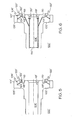
- FIG. 5 is a schematic representation of a cross-section of another alternate embodiment illustrating a modification to the embodiment shown in FIGs. 3 and 4, according to the present invention
- FIG. 6 is a schematic representation of a cross-section of another alternate embodiment illustrating a modification to the embodiment shown in FIGs. 3 and 4, according to the present invention
- FIG. 7 is a schematic representation of a cross-section of yet another alternate embodiment illustrating a modification to the meshing gear of FIGs. 3 and 4 taken along line 7-7 FIG. 8, according to the present invention.
- FIG. 8 is a schematic representation of a cross-section of the embodiment of FIG. 7 taken along line 8-8 of FIG. 7, according to the present invention.
- the present invention employs a means for applying a lubricant to the involute profile of a tooth on a meshing gear via a point of low stress in the tooth root of the gear.
- the device and method provide for the positive lubrication and maintenance of a lubricating film in meshing gears.
- FIGs. 1 and 2 illustrated is a portion of a gear 100, and more particularly a toothed wheel 102, mounted on a shaft 104, sometimes referred to as a gear assembly.
- the assembly may be one single piece of hardware, but is hereinafter referred to as an assembly.
- the shaft 104 is configured, upon receipt of a suitable drive force, to rotate.
- the shaft 104 may simply be a bore of the gear assembly.
- Toothed wheel 102 includes a plurality of meshing teeth 103 each comprised of a root portion 106 and an involute profile portion 108.
- Each tooth 103 has a load side 114 which is the side that applies or receives load from the mating gear, and a coast side 116 which is not loaded.
- a minimal stress portion 110 is located in the region near where the root portion 106 meets the involute profile portion 108 on the coast side 116. This minimal stress portion 110 is the point at which relatively low tensile stress is exhibited upon each of the meshing teeth 103.
- gear 100 is a one-way gear in which operational movement is counterclockwise as indicated by arrows 112 (FIG. 2). It should be understood that this particular type of counterclockwise gear movement is merely exemplary and that a gear that operates using one-way clockwise movement may also be used.
- each individual tooth 101 of the plurality of meshing teeth 103 may be subject to a pushing load on the load side 114 of tooth 101, and is considered to be absent a load on the coast side 116 of tooth 101.
- the load side 114 is under a pushing force at a point where the tooth 101 is being pushed by its meshing tooth (not shown).
- the highest tensile stress is exhibited on the tooth 101 typically exhibited at the root-end of the involute profile 108.
- the coast side 116 of the tooth 101 is not under a load when gear 100 is operational.
- gear 100 During operation of gear 100 under some loading conditions, loss of gear tooth contact between the plurality of teeth 103 and their meshing teeth may occur. Variations in teeth profile or dynamic motions may also cause a loss of gear tooth contact.
- a lubricant 119 such as a lubricating oil, grease, or the like, is present within an ID bore 105 of shaft 104
- the lubricant is substantially fluidic to allow for flow as described below.
- Lubricant 119 is deposited by either an external jet from outside the gear, or from elsewhere in the shaft 104 or gear bore, not shown.
- Gear 100 further includes a plurality of fluid passages 120 formed in, and circumferentially spaced about, shaft 104. Each passage 120 extends from the ID bore 105 of shaft 104 to the minimal stress portion 110 of each tooth 101. Fluid passages 120 allow the lubricant 119 to be applied to the minimal stress portion 110 of each tooth 101.
- minimal stress portion 110 of each tooth 101 is the area of the tooth 101 that has the lowest load stress. Accordingly, the passages 120 do not place further stress upon each individual tooth 101 at the load side involute profile 108, where the highest tensile stress effects are located.
- the lubricant 119 is retained axially within the bore 105 of shaft 104 by a feature 130, such as a pressed in annular plug, a circular snap ring, or other design feature.
- the lubricant 119 flows by centrifugal force from the bore 105 of shaft 104 through the plurality of passages 120 to the minimal stress portion 110 of each of the plurality of teeth 103.
- Each fluid passage 120 includes an inlet opening 122 proximate the shaft 104 and an outlet opening 124 proximate the minimal stress portion 110 of each tooth 101.
- the flow of the lubricant 119 through passages 120 and through outlet openings 124 to the minimal stress portion 110 of each tooth 101 provides lubrication to the meshing teeth 103 as the wheel is rotated. This constant, direct supply of lubrication to each meshing tooth 101 provides for the buildup of a lubricating film without increasing the stress to the plurality of teeth 103, and prevents wear of the gear teeth.
- FIGs. 3 and 4 illustrate modifications to the embodiment of FIGs. 1 and 2. Accordingly, all components of FIGs. 3 and 4 that are similar to the components illustrated in FIGs. 1 and 2, are designated with similar numbers, having a prime added to indicate the different embodiment.
- gear 100' additionally includes an annular well 118 having contained therein a lubricant 119'.
- Gear 100'further includes a plurality of fluid passages 120' formed in, and circumferentially spaced about, shaft or gear bore 104'. Each passage 120 extends from the annular well 118 to the minimal stress portion 110' of each tooth 101'. Fluid passages 120' allow the lubricant 119' to be applied to the minimal stress portion 110' of each tooth 101'. As previously stated, the passages 120' do not place further stress upon each individual tooth 101' at the load side 114' involute profile 108', where the highest tensile stress effects are located.
- Annular well 118 is in fluidic communication with the minimal stress portion 110' of each tooth 101' via passages 120'.
- the plurality of passages 120' may be formed extending from annular well 118 to each individual tooth 101'. In an alternative embodiment, the plurality of passages 120' may be formed to extend from the annular well 118 to substantially all of the individual teeth 1.01', but not each individual tooth 101'. In either case, annular well 118 is continuously fed the lubricant 119' by centrifugal force draining, as indicated by arrow 131, the shaft 104'. As mentioned previously, lubricant 119' is present within the ID bore 105 of shaft 104', deposited there either by external jet from outside the gear, or from elsewhere in the shaft or gear bore, not shown.
- the lubricant 119' flows by centrifugal force from the annular well 118 through the plurality of passages 120' to the minimal stress portion 110' of each of the plurality of teeth 103'.
- Each fluid passage 120' includes an inlet opening 122' proximate the annular well 118 and an outlet opening 124' proximate the minimal stress portion 110' of each tooth 101'.
- the flow of the lubricant 119 through passages 120 and through outlet openings 124 to the minimal stress portion 110' of each tooth 101' provides lubrication to the meshing teeth 103' as the wheel is rotated. Similar to the previously described embodiment, this constant, direct supply of lubrication to each meshing tooth 101' provides for the buildup of a lubricating film without increasing the stress to the plurality of teeth 103, and prevents wear of the gear teeth.
- FIG. 5 illustrates a variation on this embodiment where the annular well 118 is continuously fed via a lubricating jet (not shown) located in the housing static structure.
- the lubricating jet supplies the lubricant 119' directly into the annular well 118.
- FIG. 6 illustrates a variation on this embodiment where the annular well 118 is continuously fed via a plurality of fluid passages 126 which drain lubricant 119' from within the bore 105' of shaft 104'.
- the lubricant 119' is retained axially within the bore 105' of shaft 104' by a feature 130', such as a pressed in annular plug, a circular snap ring, or other design feature.
- FIGs. 7 and 8 illustrate yet another alternate modification of the previous embodiment wherein the plurality of passages 120' connect the annular well 118 to the outlet opening 124' outboard of the loaded tooth roots.
- the lubricant 119' is applied directly onto the involute profiles 108' and also onto the profiles of the meshing gear teeth (not shown) Circumferential relocation of the passages 120' may be required to optimize the lubrication requirements of the mating gear (not shown).
- Annular well is fed via any of the methods previously discussed.
- a means for lubricating a meshing gear includes a plurality of lubricating passages formed circumferentially about a shaft of a toothed wheel of a meshing gear.
- the lubricating passages are in fluidic communication with a lubricant located in the bore of the shaft or an annular well formed about the shaft and having contained therein the lubricant.
- the fluid passages are additionally in fluidic communication with a minimal stress portion of substantially all of the teeth that comprise the toothed wheel.
- the formation of the passages as this point of minimal stress does not increase the stress upon the plurality of teeth, yet provides a constant means for lubrication during loaded operating conditions.
- the fabricating of the outlet of the passages at a minimal stress portion of each of the plurality of teeth minimizes the formation of additional stress.
Landscapes
- Engineering & Computer Science (AREA)
- General Engineering & Computer Science (AREA)
- Mechanical Engineering (AREA)
- General Details Of Gearings (AREA)
Abstract
Description
- The present invention relates to the lubrication of gears. More particularly, the present invention relates to the lubrication of toothed meshing gears.
- It is well known to dispose meshing gears in a lubricant filled case. The lubricant, which may be either solid or liquid, bathes the gears, creating a lubricating field that maintains gear lubrication. Alternative means of lubricating meshing gears have been used, such as through the use of a static oil jet mounted on the gearbox structure that disperses lubricant onto the meshing teeth. Oil jet dispersion typically is achieved in one of two ways: as an into-mesh jet where oil is dispersed onto the teeth prior to meshing, or as an out-of-mesh jet where lubricant is dispersed onto the teeth as they complete the mesh. In addition, a cooling oil splash or mist has been used to lubricate meshing gears in which high speed components chum oil spray through a gearbox space.
- Insufficient lubrication between meshing gears can cause scoring, micropitting, and other forms of wear and damage to the involute profile of the gear teeth, leading to higher vibration, noise, heat, and ultimately gear tooth failure. Generally, in a meshing gear that turns in a single direction, while under a loaded condition, one side of the tooth (and one side of the tooth root) is subject to the highest stress because the load is applied adjacent to that point. More specifically, the highest tensile stress on the gear tooth is located at a point in the tooth root adjacent to where the tooth is being pushed, receiving the greatest load during the period of revolution when there is single tooth contact.
- Various attempts have been made to provide lubricating film on the gear teeth. These include providing a lubricant directly to each of the centers of the roots of the gear teeth or to the involute profile of each of the gear teeth, both highly stressed points. In general, prior attempts have formed a fluid passage hole located within this high stress region. This can be considered a rotating oil jet. Lubricant is fed to the high stress points during operation by centrifugal force. The fabrication of a passage within the tooth in this high stress region may cause an even higher stress concentration about the passage. This can exacerbate the possibility of a crack developing and the gear tooth breaking off. Attempts at providing lubrication to a lower stress point of each of the gear teeth, or to a location that is distant from the maximum stress point of the gear teeth, has not been achieved.
- Thus, there is a need for a means for lubricating a meshed gear assembly wherein a constant lubricating film is provided by a rotating jet at a minimal stress point of a plurality of gear teeth that form the meshed gears, thereby achieving a constant lubricating film during a loaded condition.
- The present invention provides a gear assembly, comprising: a shaft, a toothed wheel, a source of lubricant and a plurality of fluidic passages. The toothed wheel is mounted on the shaft and configured to rotate therewith. The toothed wheel has a plurality of teeth formed on, and extending radially from, a periphery thereof. Each of the plurality of teeth is defined by a root portion, an involute profile portion, and a minimal stress portion located between the root portion and the involute profile portion. The source of lubricant is adapted to supply a lubricant to the gear assembly, either through a bore in the shaft or from an external jet source. Each of the plurality of fluidic passages is in fluidic communication with the source of lubricant and the minimal stress portion of one of the plurality of teeth. During gear assembly operation, lubricant flows, under the influence of centrifugal force, to the minimal stress portion of each of the plurality of teeth via the plurality of fluidic passages.
- In another exemplary embodiment, provided is a gear assembly, comprising, a shaft, a toothed wheel, an annular well, and a plurality of fluidic passages. The toothed wheel is mounted on the shaft, and configured to rotate therewith. The toothed wheel includes a plurality of teeth formed on, and extending radially from, a periphery thereof. Each of the plurality of teeth is defined by a root portion, an involute profile portion, and a minimal stress portion located between the root portion and the involute profile portion. The annular well is formed in the gear assembly between the shaft and the plurality of teeth and adapted to receive a lubricant. Each of the plurality of fluidic passages is in fluidic communication with the annular well and the minimal stress portion of one of the plurality of teeth. During operation, lubricant flows, under the influence of centrifugal force, to the plurality of teeth via the fluidic passages.
- In addition, provided is a method of lubricating a plurality of teeth in a meshing gear comprising the steps of providing a shaft, configured to rotate, and a toothed wheel mounted on the shaft. The toothed wheel also configured to rotate. The method further includes the steps of providing a source of lubricant to provide lubricant to the gear assembly, and forming a plurality of fluidic passages, each fluidic passage in fluidic communication with the lubricant and the minimal stress portion of one of the plurality of teeth. The toothed wheel is configured to rotate therewith the shaft and includes a plurality of teeth formed on, and extending radially from, a periphery thereof. Each of the plurality of teeth is defined by a root portion, an involute profile portion, and a minimal stress portion located between the root portion and the involute profile portion. During gear assembly operation, lubricant flows, under the influence of centrifugal force, to the minimal stress portion of each of the plurality of teeth via the plurality of fluidic passages.
- Other independent features and advantages of the preferred positive gear lubricating assembly will become apparent from the following detailed description, taken in conjunction with the accompanying drawings which illustrate, by way of example, the principles of the invention.
- FIG. 1 is a schematic representation of a cross-section of a meshing gear taken along line 1-1 of FIG. 2 according to the present invention;
- FIG. 2 is a schematic representation of a cross-section of the meshing gear of FIG. 1 taken along line 2-2 of FIG. 1, according to the present invention;
- FIG. 3 is a schematic representation of a cross-section of an alternate embodiment of a meshing gear taken along line 3-3 of FIG. 4, according to the present invention;
- FIG. 4 is a schematic representation of a cross-section of the embodiment of FIG. 3 taken along line 4-4 of FIG. 3, according to the present invention;
- FIG. 5 is a schematic representation of a cross-section of another alternate embodiment illustrating a modification to the embodiment shown in FIGs. 3 and 4, according to the present invention;
- FIG. 6 is a schematic representation of a cross-section of another alternate embodiment illustrating a modification to the embodiment shown in FIGs. 3 and 4, according to the present invention;
- FIG. 7 is a schematic representation of a cross-section of yet another alternate embodiment illustrating a modification to the meshing gear of FIGs. 3 and 4 taken along line 7-7 FIG. 8, according to the present invention; and
- FIG. 8 is a schematic representation of a cross-section of the embodiment of FIG. 7 taken along line 8-8 of FIG. 7, according to the present invention.
- The present invention employs a means for applying a lubricant to the involute profile of a tooth on a meshing gear via a point of low stress in the tooth root of the gear. The device and method provide for the positive lubrication and maintenance of a lubricating film in meshing gears. Referring now to FIGs. 1 and 2 illustrated is a portion of a
gear 100, and more particularly atoothed wheel 102, mounted on ashaft 104, sometimes referred to as a gear assembly. The assembly may be one single piece of hardware, but is hereinafter referred to as an assembly. Theshaft 104 is configured, upon receipt of a suitable drive force, to rotate. Theshaft 104 may simply be a bore of the gear assembly. Furthermore, The drive force may be applied either to theshaft 104, which in turn causes thetoothed wheel 102 to rotate, or it may be applied to thetoothed wheel 102, which causes theshaft 104 to rotate.Toothed wheel 102 includes a plurality of meshingteeth 103 each comprised of aroot portion 106 and aninvolute profile portion 108. Eachtooth 103 has aload side 114 which is the side that applies or receives load from the mating gear, and acoast side 116 which is not loaded. Aminimal stress portion 110 is located in the region near where theroot portion 106 meets theinvolute profile portion 108 on thecoast side 116. Thisminimal stress portion 110 is the point at which relatively low tensile stress is exhibited upon each of themeshing teeth 103. - In the embodiments described,
gear 100 is a one-way gear in which operational movement is counterclockwise as indicated by arrows 112 (FIG. 2). It should be understood that this particular type of counterclockwise gear movement is merely exemplary and that a gear that operates using one-way clockwise movement may also be used. During counterclockwise gear movement, eachindividual tooth 101 of the plurality of meshingteeth 103 may be subject to a pushing load on theload side 114 oftooth 101, and is considered to be absent a load on thecoast side 116 oftooth 101. - During movement of
gear 100, theload side 114 is under a pushing force at a point where thetooth 101 is being pushed by its meshing tooth (not shown). The highest tensile stress is exhibited on thetooth 101 typically exhibited at the root-end of theinvolute profile 108. Thecoast side 116 of thetooth 101 is not under a load whengear 100 is operational. - During operation of
gear 100 under some loading conditions, loss of gear tooth contact between the plurality ofteeth 103 and their meshing teeth may occur. Variations in teeth profile or dynamic motions may also cause a loss of gear tooth contact. During operation ofgear 100, it is desirable to maintain a lubricating film on eachtooth 101 of the plurality ofteeth 103 to reduce scoring, micropitting, and other forms of wear and damage to the involute profile of the gear teeth. - In the embodiment disclosed in FIGs. 1 and 2, a
lubricant 119, such as a lubricating oil, grease, or the like, is present within anID bore 105 ofshaft 104 In a preferred embodiment the lubricant is substantially fluidic to allow for flow as described below.Lubricant 119 is deposited by either an external jet from outside the gear, or from elsewhere in theshaft 104 or gear bore, not shown.Gear 100 further includes a plurality offluid passages 120 formed in, and circumferentially spaced about,shaft 104. Eachpassage 120 extends from the ID bore 105 ofshaft 104 to theminimal stress portion 110 of eachtooth 101.Fluid passages 120 allow thelubricant 119 to be applied to theminimal stress portion 110 of eachtooth 101. As previously stated,minimal stress portion 110 of eachtooth 101 is the area of thetooth 101 that has the lowest load stress. Accordingly, thepassages 120 do not place further stress upon eachindividual tooth 101 at the load sideinvolute profile 108, where the highest tensile stress effects are located. Thelubricant 119 is retained axially within thebore 105 ofshaft 104 by afeature 130, such as a pressed in annular plug, a circular snap ring, or other design feature. - During operation, the
lubricant 119 flows by centrifugal force from thebore 105 ofshaft 104 through the plurality ofpassages 120 to theminimal stress portion 110 of each of the plurality ofteeth 103. Eachfluid passage 120 includes aninlet opening 122 proximate theshaft 104 and anoutlet opening 124 proximate theminimal stress portion 110 of eachtooth 101. The flow of thelubricant 119 throughpassages 120 and throughoutlet openings 124 to theminimal stress portion 110 of eachtooth 101 provides lubrication to the meshingteeth 103 as the wheel is rotated. This constant, direct supply of lubrication to each meshingtooth 101 provides for the buildup of a lubricating film without increasing the stress to the plurality ofteeth 103, and prevents wear of the gear teeth. - FIGs. 3 and 4 illustrate modifications to the embodiment of FIGs. 1 and 2. Accordingly, all components of FIGs. 3 and 4 that are similar to the components illustrated in FIGs. 1 and 2, are designated with similar numbers, having a prime added to indicate the different embodiment. As illustrated in FIGs. 3 and 4, gear 100' additionally includes an
annular well 118 having contained therein alubricant 119'. Gear 100'further includes a plurality of fluid passages 120' formed in, and circumferentially spaced about, shaft or gear bore 104'. Eachpassage 120 extends from the annular well 118 to the minimal stress portion 110' of each tooth 101'. Fluid passages 120' allow thelubricant 119' to be applied to the minimal stress portion 110' of each tooth 101'. As previously stated, the passages 120' do not place further stress upon each individual tooth 101' at the load side 114'involute profile 108', where the highest tensile stress effects are located. - Annular well 118 is in fluidic communication with the minimal stress portion 110' of each tooth 101' via passages 120'. The plurality of passages 120' may be formed extending from annular well 118 to each individual tooth 101'. In an alternative embodiment, the plurality of passages 120' may be formed to extend from the annular well 118 to substantially all of the individual teeth 1.01', but not each individual tooth 101'. In either case,
annular well 118 is continuously fed thelubricant 119' by centrifugal force draining, as indicated byarrow 131, the shaft 104'. As mentioned previously,lubricant 119' is present within the ID bore 105 of shaft 104', deposited there either by external jet from outside the gear, or from elsewhere in the shaft or gear bore, not shown. - During operation, the
lubricant 119' flows by centrifugal force from the annular well 118 through the plurality of passages 120' to the minimal stress portion 110' of each of the plurality of teeth 103'. Each fluid passage 120' includes an inlet opening 122' proximate theannular well 118 and an outlet opening 124' proximate the minimal stress portion 110' of each tooth 101'. The flow of thelubricant 119 throughpassages 120 and throughoutlet openings 124 to the minimal stress portion 110' of each tooth 101' provides lubrication to the meshing teeth 103' as the wheel is rotated. Similar to the previously described embodiment, this constant, direct supply of lubrication to each meshing tooth 101' provides for the buildup of a lubricating film without increasing the stress to the plurality ofteeth 103, and prevents wear of the gear teeth. - FIG. 5 illustrates a variation on this embodiment where the
annular well 118 is continuously fed via a lubricating jet (not shown) located in the housing static structure. The lubricating jet supplies thelubricant 119' directly into theannular well 118. - FIG. 6 illustrates a variation on this embodiment where the
annular well 118 is continuously fed via a plurality of fluid passages 126 which drainlubricant 119' from within the bore 105' of shaft 104'. As in the first embodiment, thelubricant 119' is retained axially within the bore 105' of shaft 104' by a feature 130', such as a pressed in annular plug, a circular snap ring, or other design feature. - FIGs. 7 and 8 illustrate yet another alternate modification of the previous embodiment wherein the plurality of passages 120' connect the annular well 118 to the outlet opening 124' outboard of the loaded tooth roots. The
lubricant 119' is applied directly onto theinvolute profiles 108' and also onto the profiles of the meshing gear teeth (not shown) Circumferential relocation of the passages 120' may be required to optimize the lubrication requirements of the mating gear (not shown). Annular well is fed via any of the methods previously discussed. - A means for lubricating a meshing gear has now been provided that includes a plurality of lubricating passages formed circumferentially about a shaft of a toothed wheel of a meshing gear. The lubricating passages are in fluidic communication with a lubricant located in the bore of the shaft or an annular well formed about the shaft and having contained therein the lubricant. The fluid passages are additionally in fluidic communication with a minimal stress portion of substantially all of the teeth that comprise the toothed wheel. The formation of the passages as this point of minimal stress does not increase the stress upon the plurality of teeth, yet provides a constant means for lubrication during loaded operating conditions. The fabricating of the outlet of the passages at a minimal stress portion of each of the plurality of teeth minimizes the formation of additional stress.
- While the invention has been described with reference to a preferred embodiment, it will be understood by those skilled in the art that various changes may be made and equivalents may be substituted for elements thereof without departing from the scope of the invention. In addition, many modifications may be made to adapt to a particular situation or material to the teachings of the invention without departing from the essential scope thereof. Therefore, it is intended that the invention not be limited to the particular embodiment disclosed as the best mode contemplated for carrying out this invention, but that the invention will include all embodiments falling within the scope of the appended claims.
Claims (10)
- A gear assembly (100), comprising:a shaft (104) configured to rotate;a toothed wheel (102) mounted on the shaft (104) and configured to rotate therewith, the toothed wheel (102) having a plurality of teeth (103) formed on, and extending radially from, a periphery thereof, each of the plurality of teeth defined by a root portion (106), an involute profile portion (108), and a minimal stress portion (110) located between the root (106) portion and the involute profile portion (110);a source of lubricant (119) adapted to supply a lubricant to the gear assembly (100); anda plurality of fluidic passages (120), each fluidic passage in fluidic communication with the source of lubricant (119) and the minimal stress portion (110) of one (101) of the plurality of teeth (103), whereby, during gear assembly operation, lubricant supplied by the source of lubricant (119) flows, under the influence of centrifugal force, to the minimal stress portion (110) of each of the plurality of teeth (103) via the plurality of fluidic passages (120).
- The device of claim 1, wherein the source of lubricant (119) is an external jet that provides lubricant to an ID bore (105) of the shaft (104).
- The device of claim 1, wherein the source of lubricant (119) is an internal source housed in the gear assembly (100) that provides lubricant to an ID bore (105) of the shaft (104).
- The device of claim 1, wherein the plurality of fluidic passages (120) are circumferentially positioned about the shaft (104).
- The device of claim 1, further including an annular well (118) formed in the gear assembly (100) between the shaft (104) and the plurality of teeth (103), the annular well (118) in fluidic communication with the source of lubricant (119) and adapted to receive the lubricant.
- The device of claim 5, wherein the plurality of fluidic passages (120) are circumferentially positioned about the annular well (118).
- The device of claim 1, wherein each of the plurality of fluidic passages (120) includes a fluid inlet (122) and a fluid outlet (124), and wherein the fluid inlet (122) in fluidic communication with the source of lubricant (119) and the fluid outlet (124) is in fluidic communication with the minimal stress portion (110) of one (101) of the plurality of teeth (103).
- The device of claim 1, wherein each (101) of the plurality of teeth (103) is in fluidic communication with a fluidic passage (120).
- The device of claim 1, wherein the lubricant (119) is a lubricating oil.
- The device of claim 1, wherein the source of lubricant (119) is one of a jet supply source, a lubricating oil, or a grease.
Applications Claiming Priority (1)
| Application Number | Priority Date | Filing Date | Title |
|---|---|---|---|
| US11/343,163 US20070175706A1 (en) | 2006-01-30 | 2006-01-30 | Positive lubrication of a meshing gear |
Publications (2)
| Publication Number | Publication Date |
|---|---|
| EP1813839A2 true EP1813839A2 (en) | 2007-08-01 |
| EP1813839A3 EP1813839A3 (en) | 2008-07-02 |
Family
ID=37908380
Family Applications (1)
| Application Number | Title | Priority Date | Filing Date |
|---|---|---|---|
| EP07101304A Withdrawn EP1813839A3 (en) | 2006-01-30 | 2007-01-29 | Positive lubrication of a meshing gear |
Country Status (3)
| Country | Link |
|---|---|
| US (1) | US20070175706A1 (en) |
| EP (1) | EP1813839A3 (en) |
| CA (1) | CA2576121A1 (en) |
Cited By (5)
| Publication number | Priority date | Publication date | Assignee | Title |
|---|---|---|---|---|
| DE102013208211A1 (en) * | 2013-05-06 | 2014-11-06 | Zf Friedrichshafen Ag | Toothed component |
| EP2873855A4 (en) * | 2012-07-10 | 2016-04-13 | Uni Politècnica De Catalunya | METHOD AND DEVICE FOR PREVENTING EXCESSIVE WEAR IN GEARS |
| EP3346164A1 (en) * | 2017-01-04 | 2018-07-11 | United Technologies Corporation | Gear with fluid control dam and apertures |
| FR3143706A1 (en) * | 2022-12-19 | 2024-06-21 | Valeo Embrayages | Pinion carrier shaft, gearbox and electric machine |
| FR3143705A1 (en) * | 2022-12-19 | 2024-06-21 | Valeo Embrayages | Gear carrier shaft, gearbox and electric machine |
Families Citing this family (13)
| Publication number | Priority date | Publication date | Assignee | Title |
|---|---|---|---|---|
| WO2009026620A1 (en) | 2007-08-24 | 2009-03-05 | Fourivers Power Engineering Pty Ltd | Marine power generation apparatus using ocean currents |
| FR2921455B1 (en) * | 2007-09-25 | 2010-01-01 | Hispano Suiza Sa | GEAR SYSTEM WITH LUBRICATION. |
| US8857286B2 (en) * | 2012-03-06 | 2014-10-14 | Luren Precision Co., Ltd. | Machine tool transmission system |
| JP6470002B2 (en) * | 2014-09-25 | 2019-02-13 | 株式会社Subaru | Gear and vehicle transmission |
| FR3041055B1 (en) * | 2015-09-16 | 2017-10-06 | Jtekt Europe Sas | GEAR REDUCER WITH INTEGRATED GREASE FOR POWER STEERING |
| JP6565620B2 (en) * | 2015-11-12 | 2019-08-28 | いすゞ自動車株式会社 | Scissor gear lubrication structure |
| DE102017202289A1 (en) | 2017-02-14 | 2018-08-16 | Zf Friedrichshafen Ag | Shaft, especially gear shaft |
| US11105411B2 (en) * | 2018-02-28 | 2021-08-31 | Sikorsky Aircraft Corporation | Secondary lubrication for gears and gearboxes |
| FR3109602B1 (en) * | 2020-04-22 | 2023-03-24 | Safran Trans Systems | Sprocket with a lubricating device |
| EP3974681A1 (en) * | 2020-09-29 | 2022-03-30 | Volvo Truck Corporation | A gearwheel arrangement |
| EP3974682B1 (en) | 2020-09-29 | 2024-06-26 | Volvo Truck Corporation | A gearwheel arrangement |
| US12140221B2 (en) * | 2022-09-26 | 2024-11-12 | Dana Italia S.R.L. | Lubrication assembly with a lubricant conveyor |
| US12612965B2 (en) * | 2023-02-15 | 2026-04-28 | The Boeing Company | Methods and apparatus to passively lubricate a worm gear assembly |
Family Cites Families (19)
| Publication number | Priority date | Publication date | Assignee | Title |
|---|---|---|---|---|
| US1186434A (en) * | 1913-01-10 | 1916-06-06 | Link Belt Co | Lubricating-wheel for chain-drives. |
| US2535703A (en) * | 1949-01-12 | 1950-12-26 | Gen Electric | Lubricating system for gear units |
| US3424022A (en) * | 1967-01-23 | 1969-01-28 | Babcock & Wilcox Co | Hydrostatic gearing |
| US3608672A (en) * | 1969-03-10 | 1971-09-28 | Gerard W Dandridge | Automatic gear lubricator |
| DE2123557B1 (en) * | 1971-05-12 | 1972-05-31 | G Schwartz & Co | Lubricating device for rolling spindles in rolling mills |
| NO129163B (en) * | 1971-07-15 | 1974-03-04 | N Tharaldsen | |
| JPS59208265A (en) * | 1983-05-09 | 1984-11-26 | Niles Parts Co Ltd | Lubrication device for gear |
| JPS61180063A (en) * | 1984-09-12 | 1986-08-12 | Toshiba Mach Co Ltd | Statical pressure worm rack |
| US4957187A (en) * | 1988-08-15 | 1990-09-18 | Burgess & Associates Mfg., Inc. | Gear-driven lubricant circulation system |
| GB9218364D0 (en) * | 1992-08-28 | 1992-10-14 | Black & Decker Inc | Gear lubrication |
| US5472383A (en) * | 1993-12-27 | 1995-12-05 | United Technologies Corporation | Lubrication system for a planetary gear train |
| US5622239A (en) * | 1995-07-14 | 1997-04-22 | A.T.S. Electro-Lube Holdings Ltd. | Gear wheel lubricator |
| DE19613325C1 (en) * | 1996-04-03 | 1997-07-24 | Fichtel & Sachs Ag | Torsional vibration damper with a lubricant supply for a planet gear |
| JP2001208173A (en) * | 2000-01-28 | 2001-08-03 | Nissan Motor Co Ltd | Gear centrifugal lubrication device |
| JP2002021978A (en) * | 2000-07-06 | 2002-01-23 | Enplas Corp | Resin-made gear and metal molding structure |
| JP2002156029A (en) * | 2000-11-17 | 2002-05-31 | Dainippon Printing Co Ltd | How to supply lubricant to gear meshing part |
| US7022039B2 (en) * | 2003-09-11 | 2006-04-04 | Komatsu America Corp. | Lubrication system for planetary transmission |
| US20060053922A1 (en) * | 2004-09-03 | 2006-03-16 | Laabs Erich A | Lubrication system for supplying lubricant between intermeshing gear teeth |
| DE202006011330U1 (en) * | 2006-05-16 | 2006-09-28 | Lincoln Gmbh & Co. Kg | Lubricating device for applying lubricating grease from a reservoir container to a gearwheel via a pipe from a lubricant pump has a lubricating pinion gear |
-
2006
- 2006-01-30 US US11/343,163 patent/US20070175706A1/en not_active Abandoned
-
2007
- 2007-01-29 CA CA002576121A patent/CA2576121A1/en not_active Abandoned
- 2007-01-29 EP EP07101304A patent/EP1813839A3/en not_active Withdrawn
Non-Patent Citations (1)
| Title |
|---|
| None |
Cited By (5)
| Publication number | Priority date | Publication date | Assignee | Title |
|---|---|---|---|---|
| EP2873855A4 (en) * | 2012-07-10 | 2016-04-13 | Uni Politècnica De Catalunya | METHOD AND DEVICE FOR PREVENTING EXCESSIVE WEAR IN GEARS |
| DE102013208211A1 (en) * | 2013-05-06 | 2014-11-06 | Zf Friedrichshafen Ag | Toothed component |
| EP3346164A1 (en) * | 2017-01-04 | 2018-07-11 | United Technologies Corporation | Gear with fluid control dam and apertures |
| FR3143706A1 (en) * | 2022-12-19 | 2024-06-21 | Valeo Embrayages | Pinion carrier shaft, gearbox and electric machine |
| FR3143705A1 (en) * | 2022-12-19 | 2024-06-21 | Valeo Embrayages | Gear carrier shaft, gearbox and electric machine |
Also Published As
| Publication number | Publication date |
|---|---|
| US20070175706A1 (en) | 2007-08-02 |
| CA2576121A1 (en) | 2007-07-30 |
| EP1813839A3 (en) | 2008-07-02 |
Similar Documents
| Publication | Publication Date | Title |
|---|---|---|
| CA2576121A1 (en) | Positive lubrication of a meshing gear | |
| US7984791B2 (en) | Oil discharge structure of baffle plate | |
| US8033941B2 (en) | Lubricating oil feeding device for automatic transmission | |
| US8708105B2 (en) | Transmission with splash lubrication system | |
| EP1994276B1 (en) | Lubrication structure of cranking rotational force transmission mechanism for internal combustion engine | |
| US9851001B2 (en) | Drive unit for vehicles | |
| US20080268997A1 (en) | Lubrication path in a planetary gear unit for a transmission | |
| GB2514877A (en) | Spline lubrication system | |
| US20090133650A1 (en) | Valve timing control apparatus | |
| CN108458056B (en) | Eccentric oscillating gear device | |
| CN106015534B (en) | Differential gear | |
| US8573361B2 (en) | Lubricating structure of a rotational shaft oil sealing portion | |
| EP2410208A2 (en) | Motion transmitting apparatus having an oil-lubricated gear clearance eliminating device | |
| US20040094364A1 (en) | Lubrication system for high speed planet gears | |
| KR20090060524A (en) | Idle Gear Assembly with Improved Lubrication Performance | |
| JP2007170540A (en) | Gear meshing portion lubricating structure | |
| US9816582B2 (en) | Balancer device for internal combustion engine | |
| JP6122786B2 (en) | Lubrication structure of differential equipment | |
| JP4229274B2 (en) | Oiling device for centrifugal clutch of internal combustion engine | |
| JP2001153212A (en) | Planetary gear set | |
| JP6245647B2 (en) | Gear bearing lubrication structure | |
| US20060054415A1 (en) | Oil thrower disk | |
| US10914358B2 (en) | Balancer device for internal combustion engine | |
| JP3751156B2 (en) | Lubricating oil supply mechanism for vertical shaft transmission | |
| JP2004144222A (en) | Gear |
Legal Events
| Date | Code | Title | Description |
|---|---|---|---|
| PUAI | Public reference made under article 153(3) epc to a published international application that has entered the european phase |
Free format text: ORIGINAL CODE: 0009012 |
|
| AK | Designated contracting states |
Kind code of ref document: A2 Designated state(s): AT BE BG CH CY CZ DE DK EE ES FI FR GB GR HU IE IS IT LI LT LU LV MC NL PL PT RO SE SI SK TR |
|
| AX | Request for extension of the european patent |
Extension state: AL BA HR MK RS |
|
| PUAL | Search report despatched |
Free format text: ORIGINAL CODE: 0009013 |
|
| AK | Designated contracting states |
Kind code of ref document: A3 Designated state(s): AT BE BG CH CY CZ DE DK EE ES FI FR GB GR HU IE IS IT LI LT LU LV MC NL PL PT RO SE SI SK TR |
|
| AX | Request for extension of the european patent |
Extension state: AL BA HR MK RS |
|
| STAA | Information on the status of an ep patent application or granted ep patent |
Free format text: STATUS: THE APPLICATION HAS BEEN WITHDRAWN |
|
| 18W | Application withdrawn |
Effective date: 20090107 |
|
| 17P | Request for examination filed |
Effective date: 20081224 |