EP1813783A1 - Cam phaser apparatus - Google Patents
Cam phaser apparatus Download PDFInfo
- Publication number
- EP1813783A1 EP1813783A1 EP06256132A EP06256132A EP1813783A1 EP 1813783 A1 EP1813783 A1 EP 1813783A1 EP 06256132 A EP06256132 A EP 06256132A EP 06256132 A EP06256132 A EP 06256132A EP 1813783 A1 EP1813783 A1 EP 1813783A1
- Authority
- EP
- European Patent Office
- Prior art keywords
- members
- gear system
- triple
- cam phaser
- coupling
- Prior art date
- Legal status (The legal status is an assumption and is not a legal conclusion. Google has not performed a legal analysis and makes no representation as to the accuracy of the status listed.)
- Granted
Links
Images


Classifications
-
- F—MECHANICAL ENGINEERING; LIGHTING; HEATING; WEAPONS; BLASTING
- F01—MACHINES OR ENGINES IN GENERAL; ENGINE PLANTS IN GENERAL; STEAM ENGINES
- F01L—CYCLICALLY OPERATING VALVES FOR MACHINES OR ENGINES
- F01L1/00—Valve-gear or valve arrangements, e.g. lift-valve gear
- F01L1/34—Valve-gear or valve arrangements, e.g. lift-valve gear characterised by the provision of means for changing the timing of the valves without changing the duration of opening and without affecting the magnitude of the valve lift
- F01L1/344—Valve-gear or valve arrangements, e.g. lift-valve gear characterised by the provision of means for changing the timing of the valves without changing the duration of opening and without affecting the magnitude of the valve lift changing the angular relationship between crankshaft and camshaft, e.g. using helicoidal gear
- F01L1/352—Valve-gear or valve arrangements, e.g. lift-valve gear characterised by the provision of means for changing the timing of the valves without changing the duration of opening and without affecting the magnitude of the valve lift changing the angular relationship between crankshaft and camshaft, e.g. using helicoidal gear using bevel or epicyclic gear
-
- F—MECHANICAL ENGINEERING; LIGHTING; HEATING; WEAPONS; BLASTING
- F01—MACHINES OR ENGINES IN GENERAL; ENGINE PLANTS IN GENERAL; STEAM ENGINES
- F01L—CYCLICALLY OPERATING VALVES FOR MACHINES OR ENGINES
- F01L1/00—Valve-gear or valve arrangements, e.g. lift-valve gear
- F01L1/34—Valve-gear or valve arrangements, e.g. lift-valve gear characterised by the provision of means for changing the timing of the valves without changing the duration of opening and without affecting the magnitude of the valve lift
- F01L1/344—Valve-gear or valve arrangements, e.g. lift-valve gear characterised by the provision of means for changing the timing of the valves without changing the duration of opening and without affecting the magnitude of the valve lift changing the angular relationship between crankshaft and camshaft, e.g. using helicoidal gear
- F01L1/352—Valve-gear or valve arrangements, e.g. lift-valve gear characterised by the provision of means for changing the timing of the valves without changing the duration of opening and without affecting the magnitude of the valve lift changing the angular relationship between crankshaft and camshaft, e.g. using helicoidal gear using bevel or epicyclic gear
- F01L2001/3521—Harmonic drive of flexspline type
-
- F—MECHANICAL ENGINEERING; LIGHTING; HEATING; WEAPONS; BLASTING
- F16—ENGINEERING ELEMENTS AND UNITS; GENERAL MEASURES FOR PRODUCING AND MAINTAINING EFFECTIVE FUNCTIONING OF MACHINES OR INSTALLATIONS; THERMAL INSULATION IN GENERAL
- F16H—GEARING
- F16H49/00—Other gearings
- F16H49/001—Wave gearings, e.g. harmonic drive transmissions
Definitions
- the present invention relates to a cam phaser apparatus, particularly, but not exclusively a variable cam phaser apparatus used in valve trains of automobile engines.
- cam phase i.e. the angular relationship between the crankshaft and the camshaft
- Such system are required to efficiently convert rotational movement from the crankshaft into rotational movement of the camshaft whilst allowing dislocation between these rotational movements in order to allow variation of the cam phase.
- triple member system equivalent to a planetary gear system comprises a magnetic gear having an outer ring comprising a plurality of magnets (equivalent to the ring gear), a concentric inner ring comprising a plurality of circumferentially spaced magnets (equivalent to a sun gear) and an intermediate ring or carrier member mounted in an annular space between said outer and inner rings and comprising a plurality of circumferentially spaced pole pieces (equivalent to planetary carrier upon which a plurality of planetary gears are mounted).
- one shaft is connected to the cam sprocket or pulley to comprise a drive member (typically the planet carrier or circular spline) and a second shaft is connected to the camshaft (typically the ring gear or the flex-spline) to comprise a driven member, the remaining third shaft (typically the sun gear or wave generator) being connected to an actuator for varying the cam phase (i.e. the angular relationship between the drive and driven members).
- a drive member typically the planet carrier or circular spline
- the camshaft typically the ring gear or the flex-spline
- the remaining third shaft typically the sun gear or wave generator
- a particular problem with such known triple shaft gear systems is that the position and/or angular velocity of the third shaft must be controlled at all times to prevent uncontrolled cam phase change.
- the actuator typically an electric motor, must be powered at all times, leading to increased power consumption.
- a cam phaser apparatus comprising a triple member gear system, such as a planetary gear system, harmonic drive or magnetic gear, for transferring a driving torque from a drive member to a driven member and for selectively adjusting the angular relationship between the drive and driven members, said triple member gear system comprising a first member comprising a driving part of said triple member gear system, a second member comprising a driven part of said triple member gear system connectable to a cam sprocket or pulley, and a third member comprising an adjusting means of said triple member gear system connectable to a camshaft, said third member being connected to means for rotating said third member or applying a braking torque and/or a motoring torque to said third member to vary the angular relationship between the first and second members, wherein the cam phaser apparatus further comprises a selectively actuable coupling means for selectively coupling two of said first, second and third members.
- a triple member gear system such as a planetary gear system, harmonic drive or magnetic gear
- said coupling means comprises a magnetic coupling, more preferably an electromagnetic coupling.
- the coupling means may comprise first and second rotatably mounted coaxial members, a first member connected to one of said three members of the triple member gear system, a second member connected to another of said three members of the triple member gear system, said first and second members being spaced apart from one another, one of said first and second members comprising at least one magnetically conductive region and the other of said first and second members incorporating means for selectively generating a magnetic flux to constrain the first and second members to rotate together.
- said means for selectively generating a magnetic flux comprises a solenoid.
- first and second members of said coupling means respectively comprise concentrically arranged inner and outer rotors having a radial gap therebetween.
- first and second members of said coupling means comprise axially spaced members having respective axially spaced opposing face portions.
- the coupling means may comprise a selectively actuable mechanical coupling, such as a mechanical clutch arrangement.
- the cam phaser apparatus includes a first member 1 of a triple member gear system, said first member 1 being connected to a crankshaft of the engine via a pulley or cam sprocket and an endless belt or chain.
- first member 1 could be the planet carrier and planetary gears.
- first member 1 could be the circular spline.
- first member 1 could be the intermediate ring or pole pieces.
- the camshaft of the engine is connected to a second member 2 of the triple member gear system.
- the second member 2 could be the ring gear.
- the second member 2 could be the flex-spline.
- the second member 2 could be the outer ring.
- a third member 3 of the triple member gear system is connected to an electric motor 4 for altering the cam phase of the engine.
- the third member 3 could be the sun gear.
- the third member 3 could be the wave generator.
- the third member 3 could be the inner ring.
- the housing of the motor is fixed with respect to the cylinder head while the rotor of the motor rotates with the camshaft.
- a braking torque is applied to the third member 3 by the electric motor 4 to decelerate the third member 3, thus advancing the camshaft angle with respect to the crankshaft.
- a motoring torque is applied to the third member 3 by the electric motor to accelerate the third member 3, thus retarding the camshaft angle with respect to the crankshaft.
- a magnetic coupling means 5 is provided between the second member 2 and the third member 3 to selectively couple the second and third members 2,3 together, causing all three member to rotate together at the same speed.
- the magnetic coupling means 5 comprising an inner rotor 10 and a concentrically arranged outer rotor 12, an annular gap being defined between said inner and outer rotors 10,12 whereby the two rotors can rotate independently.
- the inner rotor 10 is connected to one of the second and third members (or possibly even the first member) and the outer rotor 12 is connected to the other of the second and third members.
- Both inner and outer rotors may comprise either permanent magnets or electromagnets through a electrically driven coil to generate magnetic flux interaction between the inner and outer rotors to transfer torque between the inner and outer rotors and lock the inner and outer rotors together.
- the magnetic coupling means 5 comprises axially spaced first and second members 20,22 having respective face members axially spaced from one another to define cooperating face portions. Both discs will include either permanent magnets or electromagnets through a electrically driven coil to generate magnetic flux interaction between the inner and outer rotors to transfer torque between the inner and outer rotors and lock the inner and outer rotors together.
Landscapes
- Engineering & Computer Science (AREA)
- Mechanical Engineering (AREA)
- General Engineering & Computer Science (AREA)
- Valve Device For Special Equipments (AREA)
- Valve-Gear Or Valve Arrangements (AREA)
- Power Steering Mechanism (AREA)
Abstract
Description
- The present invention relates to a cam phaser apparatus, particularly, but not exclusively a variable cam phaser apparatus used in valve trains of automobile engines.
- It is desirable to be able to adjust the cam phase (i.e. the angular relationship between the crankshaft and the camshaft) of engines during engine operation in order to vary the timing of the opening and closing of the inlet and/or exhaust valves to improve engine performance, emissions and/or fuel consumption. Various types of arrangements exist that are capable of achieving this adjustment. Such system are required to efficiently convert rotational movement from the crankshaft into rotational movement of the camshaft whilst allowing dislocation between these rotational movements in order to allow variation of the cam phase.
- Current systems typically utilise hydraulic actuators using high pressure oil to enable relative angular displacement between drive and driven members (e.g. cam sprocket or pulley and camshaft) of the valve train. Such systems have difficulty operating at extremes of temperature, in particular during engine start up when the oil is cold, due to temperature related viscosity changes of the oil.
- Whilst attempts have been made to design electrically actuated variable cam phase arrangement, such usually require a complex triple shaft arrangement such as planetary gears or a harmonic drive arrangement. The complex arrangement of such triple shaft systems can introduce controllability and reliability problems and generally suffer from high power consumption.
- Examples of triple shaft gear systems suitable for use with a cam phaser comprise planetary gear systems (as shown in Fig. 1), with a
sun gear 1planetary gears 2 mounted on aplanet carrier 3 andring gear 4, or harmonic drive systems (as shown in Fig. 2), with a wave generator 1', flex-spline 2' and circular spline 3'. - Another form of triple member system equivalent to a planetary gear system comprises a magnetic gear having an outer ring comprising a plurality of magnets (equivalent to the ring gear), a concentric inner ring comprising a plurality of circumferentially spaced magnets (equivalent to a sun gear) and an intermediate ring or carrier member mounted in an annular space between said outer and inner rings and comprising a plurality of circumferentially spaced pole pieces (equivalent to planetary carrier upon which a plurality of planetary gears are mounted).
- Typically, where such triple shaft gear systems are applied to a cam phaser of an engine, one shaft is connected to the cam sprocket or pulley to comprise a drive member (typically the planet carrier or circular spline) and a second shaft is connected to the camshaft (typically the ring gear or the flex-spline) to comprise a driven member, the remaining third shaft (typically the sun gear or wave generator) being connected to an actuator for varying the cam phase (i.e. the angular relationship between the drive and driven members).
- A particular problem with such known triple shaft gear systems is that the position and/or angular velocity of the third shaft must be controlled at all times to prevent uncontrolled cam phase change. Hence the actuator, typically an electric motor, must be powered at all times, leading to increased power consumption.
- According to the present invention there is provided a cam phaser apparatus comprising a triple member gear system, such as a planetary gear system, harmonic drive or magnetic gear, for transferring a driving torque from a drive member to a driven member and for selectively adjusting the angular relationship between the drive and driven members, said triple member gear system comprising a first member comprising a driving part of said triple member gear system, a second member comprising a driven part of said triple member gear system connectable to a cam sprocket or pulley, and a third member comprising an adjusting means of said triple member gear system connectable to a camshaft, said third member being connected to means for rotating said third member or applying a braking torque and/or a motoring torque to said third member to vary the angular relationship between the first and second members, wherein the cam phaser apparatus further comprises a selectively actuable coupling means for selectively coupling two of said first, second and third members.
- By coupling two of the three member together, all three members are constrained to rotate synchronously, preventing alteration of the cam phasing.
- Preferably said coupling means comprises a magnetic coupling, more preferably an electromagnetic coupling.
- The coupling means may comprise first and second rotatably mounted coaxial members, a first member connected to one of said three members of the triple member gear system, a second member connected to another of said three members of the triple member gear system, said first and second members being spaced apart from one another, one of said first and second members comprising at least one magnetically conductive region and the other of said first and second members incorporating means for selectively generating a magnetic flux to constrain the first and second members to rotate together. Preferably said means for selectively generating a magnetic flux comprises a solenoid.
- In one embodiment said first and second members of said coupling means respectively comprise concentrically arranged inner and outer rotors having a radial gap therebetween. In an alternative embodiment said first and second members of said coupling means comprise axially spaced members having respective axially spaced opposing face portions.
- It is also envisaged that the coupling means may comprise a selectively actuable mechanical coupling, such as a mechanical clutch arrangement.
- Embodiment of the present invention will now be described, by way of example only, with reference to the accompanying drawings, in which:
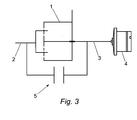
- Fig. 3 is a schematic view of a cam phaser apparatus according to an embodiment of the present invention;
- Fig. 4 is an exploded view of a magnetic coupling of a cam phaser apparatus according to a first embodiment of the present invention and;
- Fig. 5 is a perspective view of a magnetic coupling according to a second embodiment of the present invention.
- As illustrated in Fig 3, the cam phaser apparatus includes a
first member 1 of a triple member gear system, saidfirst member 1 being connected to a crankshaft of the engine via a pulley or cam sprocket and an endless belt or chain. In the case of a planetary gear system, suchfirst member 1 could be the planet carrier and planetary gears. In the case of a harmonic drive, thefirst member 1 could be the circular spline. In the case of a magnetic gear, thefirst member 1 could be the intermediate ring or pole pieces. - The camshaft of the engine is connected to a
second member 2 of the triple member gear system. In the case of a planetary gear system thesecond member 2 could be the ring gear. In the case of a harmonic drive, thesecond member 2 could be the flex-spline. In the case of a magnetic gear, thesecond member 2 could be the outer ring. - A
third member 3 of the triple member gear system is connected to anelectric motor 4 for altering the cam phase of the engine. In the case of a planetary gear system, thethird member 3 could be the sun gear. In the case of a harmonic drive, thethird member 3 could be the wave generator. In the case of a magnetic gear, thethird member 3 could be the inner ring. The housing of the motor is fixed with respect to the cylinder head while the rotor of the motor rotates with the camshaft. - When it is desired to advance the cam phase of the camshaft, a braking torque is applied to the
third member 3 by theelectric motor 4 to decelerate thethird member 3, thus advancing the camshaft angle with respect to the crankshaft. - When it is desired to retard the cam phase of the cam shaft, a motoring torque is applied to the
third member 3 by the electric motor to accelerate thethird member 3, thus retarding the camshaft angle with respect to the crankshaft. - When no advance is required it would formally have been necessary to maintain power to the
motor 4 to ensure that themotor 4 compensates for the natural tendency of the motor to decelerate due to frictional losses. To avoid this, a magnetic coupling means 5 is provided between thesecond member 2 and thethird member 3 to selectively couple the second andthird members - In a first embodiment, as illustrated in Fig 4, the magnetic coupling means 5 comprising an
inner rotor 10 and a concentrically arrangedouter rotor 12, an annular gap being defined between said inner andouter rotors inner rotor 10 is connected to one of the second and third members (or possibly even the first member) and theouter rotor 12 is connected to the other of the second and third members. Both inner and outer rotors may comprise either permanent magnets or electromagnets through a electrically driven coil to generate magnetic flux interaction between the inner and outer rotors to transfer torque between the inner and outer rotors and lock the inner and outer rotors together. - In a second embodiment, as illustrated in Fig 5, the magnetic coupling means 5 comprises axially spaced first and
second members
Claims (7)
- A cam phaser apparatus comprising a triple member gear system, such as a planetary gear system, harmonic drive or magnetic gear, for transferring a driving torque from a drive member to a driven member and for selectively adjusting the angular relationship between the drive and driven members, said triple member gear system comprising a first member comprising a driving part of said triple member gear system, a second member comprising a driven part of said triple member gear system connectable to a cam sprocket or pulley, and a third member comprising an adjusting means of said triple member gear system connectable to a camshaft, said third member being connected to means for rotating said third member or applying a braking torque and/or a motoring torque to said third member to vary the angular relationship between the first and second members, wherein the cam phaser apparatus further comprises a selectively actuable coupling means for selectively coupling two of said first, second and third members.
- A cam phaser apparatus as claimed in claim 1, wherein said coupling means comprises a magnetic coupling, more preferably an electromagnetic coupling.
- A cam phaser as claimed in any preceding claim, wherein the coupling means comprises first and second rotatably mounted coaxial members, a first member connected to one of said three members of the triple member gear system, a second member connected to another of said three members of the triple member gear system, said first and second members being spaced apart from one another, one of said first and second members comprising at least one magnetically conductive region and the other of said first and second members incorporating means for selectively generating a magnetic flux to constrain the first and second members to rotate together.
- A cam phaser apparatus as claimed in claim 3, wherein said means for selectively generating a magnetic flux comprises a solenoid.
- A cam phaser apparatus as claimed in claim 4, wherein said first and second members of said coupling means respectively comprise concentrically arranged inner and outer rotors having a radial gap therebetween.
- A cam phaser as claimed in claim 4, wherein said first and second members of said coupling means comprise axially spaced members having respective axially spaced opposing face portions.
- A cam phaser as claimed in claim 1, wherein said coupling means may comprise a selectively actuable mechanical coupling.
Priority Applications (2)
| Application Number | Priority Date | Filing Date | Title |
|---|---|---|---|
| JP2007001617A JP2007198376A (en) | 2006-01-26 | 2007-01-09 | Variable cam phase device |
| US11/652,396 US7647904B2 (en) | 2006-01-26 | 2007-01-11 | Variable cam phaser apparatus |
Applications Claiming Priority (1)
| Application Number | Priority Date | Filing Date | Title |
|---|---|---|---|
| GBGB0601590.3A GB0601590D0 (en) | 2006-01-26 | 2006-01-26 | Cam drive apparatus and method |
Publications (2)
| Publication Number | Publication Date |
|---|---|
| EP1813783A1 true EP1813783A1 (en) | 2007-08-01 |
| EP1813783B1 EP1813783B1 (en) | 2008-05-07 |
Family
ID=36060916
Family Applications (1)
| Application Number | Title | Priority Date | Filing Date |
|---|---|---|---|
| EP06256132A Not-in-force EP1813783B1 (en) | 2006-01-26 | 2006-11-30 | Cam phaser apparatus |
Country Status (4)
| Country | Link |
|---|---|
| EP (1) | EP1813783B1 (en) |
| AT (1) | ATE394584T1 (en) |
| DE (1) | DE602006001101D1 (en) |
| GB (1) | GB0601590D0 (en) |
Cited By (5)
| Publication number | Priority date | Publication date | Assignee | Title |
|---|---|---|---|---|
| EP1895114A1 (en) * | 2006-08-22 | 2008-03-05 | Delphi Technologies, Inc. | Harmonic drive camshaft phaser |
| CN102762824A (en) * | 2010-02-24 | 2012-10-31 | 德尔菲技术公司 | Electrical camshaft phaser with energy recovery |
| US10132210B1 (en) | 2017-05-16 | 2018-11-20 | Schaeffler Technologies AG & Co. KG | Electric camshaft phaser with detent and method thereof |
| US10294831B2 (en) | 2017-06-23 | 2019-05-21 | Schaeffler Technologies AG & Co. KG | Cam phasing assemblies with electromechanical locking control and method thereof |
| DE112017004867T5 (en) | 2016-09-28 | 2019-08-14 | Schaeffler Technologies AG & Co. KG | Electric camshaft adjusting system comprising an activatable lock |
Families Citing this family (3)
| Publication number | Priority date | Publication date | Assignee | Title |
|---|---|---|---|---|
| US9016250B2 (en) | 2013-06-18 | 2015-04-28 | Delphi Technologies, Inc. | Camshaft phaser |
| US9664073B2 (en) | 2014-02-25 | 2017-05-30 | Delphi Technologies, Inc. | Modular electrically actuated camshaft phaser |
| US9151191B1 (en) | 2014-04-01 | 2015-10-06 | Delphi Technologies, Inc. | Electrically actuated camshaft phaser |
Citations (6)
| Publication number | Priority date | Publication date | Assignee | Title |
|---|---|---|---|---|
| JPH0211809A (en) * | 1988-06-29 | 1990-01-16 | Aisin Seiki Co Ltd | Valve opening/closing timing controller |
| DE4110195A1 (en) * | 1991-03-28 | 1992-10-01 | Schaeffler Waelzlager Kg | Camshaft advancer for improving efficiency of combustion engine - uses slip-ring-free electric motor to alter position of camshaft relative to camshaft gear using planetary gearbox |
| EP1039101A2 (en) * | 1999-03-23 | 2000-09-27 | TCG UNITECH Aktiengesellschaft | Camshaft phaser for an internal combustion engine |
| EP1039100A2 (en) * | 1999-03-23 | 2000-09-27 | TCG UNITECH Aktiengesellschaft | Camshaft phaser for an internal combustion engine |
| WO2004007919A1 (en) * | 2002-07-11 | 2004-01-22 | Ina-Schaeffler Kg | Control structure for the adjusting motor of an electric camshaft adjuster |
| WO2005061861A1 (en) * | 2003-11-28 | 2005-07-07 | Daimlerchrysler Ag | Adjusting device for a camshaft of an internal combustion engine |
-
2006
- 2006-01-26 GB GBGB0601590.3A patent/GB0601590D0/en not_active Ceased
- 2006-11-30 EP EP06256132A patent/EP1813783B1/en not_active Not-in-force
- 2006-11-30 AT AT06256132T patent/ATE394584T1/en not_active IP Right Cessation
- 2006-11-30 DE DE602006001101T patent/DE602006001101D1/en active Active
Patent Citations (6)
| Publication number | Priority date | Publication date | Assignee | Title |
|---|---|---|---|---|
| JPH0211809A (en) * | 1988-06-29 | 1990-01-16 | Aisin Seiki Co Ltd | Valve opening/closing timing controller |
| DE4110195A1 (en) * | 1991-03-28 | 1992-10-01 | Schaeffler Waelzlager Kg | Camshaft advancer for improving efficiency of combustion engine - uses slip-ring-free electric motor to alter position of camshaft relative to camshaft gear using planetary gearbox |
| EP1039101A2 (en) * | 1999-03-23 | 2000-09-27 | TCG UNITECH Aktiengesellschaft | Camshaft phaser for an internal combustion engine |
| EP1039100A2 (en) * | 1999-03-23 | 2000-09-27 | TCG UNITECH Aktiengesellschaft | Camshaft phaser for an internal combustion engine |
| WO2004007919A1 (en) * | 2002-07-11 | 2004-01-22 | Ina-Schaeffler Kg | Control structure for the adjusting motor of an electric camshaft adjuster |
| WO2005061861A1 (en) * | 2003-11-28 | 2005-07-07 | Daimlerchrysler Ag | Adjusting device for a camshaft of an internal combustion engine |
Cited By (7)
| Publication number | Priority date | Publication date | Assignee | Title |
|---|---|---|---|---|
| EP1895114A1 (en) * | 2006-08-22 | 2008-03-05 | Delphi Technologies, Inc. | Harmonic drive camshaft phaser |
| US7421990B2 (en) | 2006-08-22 | 2008-09-09 | Delphi Technologies, Inc. | Harmonic drive camshaft phaser |
| CN102762824A (en) * | 2010-02-24 | 2012-10-31 | 德尔菲技术公司 | Electrical camshaft phaser with energy recovery |
| CN102762824B (en) * | 2010-02-24 | 2014-11-26 | 德尔菲技术公司 | Electrical camshaft phaser with energy recovery |
| DE112017004867T5 (en) | 2016-09-28 | 2019-08-14 | Schaeffler Technologies AG & Co. KG | Electric camshaft adjusting system comprising an activatable lock |
| US10132210B1 (en) | 2017-05-16 | 2018-11-20 | Schaeffler Technologies AG & Co. KG | Electric camshaft phaser with detent and method thereof |
| US10294831B2 (en) | 2017-06-23 | 2019-05-21 | Schaeffler Technologies AG & Co. KG | Cam phasing assemblies with electromechanical locking control and method thereof |
Also Published As
| Publication number | Publication date |
|---|---|
| ATE394584T1 (en) | 2008-05-15 |
| GB0601590D0 (en) | 2006-03-08 |
| EP1813783B1 (en) | 2008-05-07 |
| DE602006001101D1 (en) | 2008-06-19 |
Similar Documents
| Publication | Publication Date | Title |
|---|---|---|
| US7647904B2 (en) | Variable cam phaser apparatus | |
| EP2539556B1 (en) | Electrical camshaft phaser with energy recovery | |
| EP2006501A1 (en) | Variable cam phaser apparatus | |
| US10006321B2 (en) | Engine variable camshaft timing phaser with planetary gear set | |
| CN103348100B (en) | The concentricity quarter-phase device being assembled in concentric camshaft system | |
| EP1895114A1 (en) | Harmonic drive camshaft phaser | |
| US20090120388A1 (en) | Electro-hydraulic hybrid camshaft phaser | |
| US7562645B2 (en) | Electromechanical camshaft phaser having a worm gear drive with a hypoid gear actuator | |
| KR101542966B1 (en) | Valve Train Layout Structure Including Cam Phaser and Camshaft-In-Camshaft | |
| US11125121B2 (en) | Dual actuating variable cam | |
| CN102439265A (en) | Phaser assembly for an internal combustion engine | |
| WO2016036529A1 (en) | Engine variable camshaft timing phaser with planetary gear assembly | |
| EP1813783B1 (en) | Cam phaser apparatus | |
| JP5391461B2 (en) | Camshaft unit | |
| US20030159670A1 (en) | Worm gear driven variable cam phaser | |
| WO2014008988A1 (en) | Chain-based transfer device | |
| JP2013536362A (en) | Valve train for piston engines | |
| EP2009254A1 (en) | Variable cam phaser apparatus | |
| EP1788201B1 (en) | Cam drive apparatus and method | |
| JP3917833B2 (en) | Valve timing control device for internal combustion engine | |
| EP1801367A1 (en) | Variable cam phaser apparatus | |
| KR20110104009A (en) | Mini electric cam phaser | |
| JP2007239642A (en) | Valve timing adjustment device | |
| CN108223033B (en) | Camshaft deactivation system for internal combustion engine | |
| EP2017436A1 (en) | Variable cam phaser apparatus |
Legal Events
| Date | Code | Title | Description |
|---|---|---|---|
| PUAI | Public reference made under article 153(3) epc to a published international application that has entered the european phase |
Free format text: ORIGINAL CODE: 0009012 |
|
| AK | Designated contracting states |
Kind code of ref document: A1 Designated state(s): AT BE BG CH CY CZ DE DK EE ES FI FR GB GR HU IE IS IT LI LT LU LV MC NL PL PT RO SE SI SK TR |
|
| AX | Request for extension of the european patent |
Extension state: AL BA HR MK YU |
|
| 17P | Request for examination filed |
Effective date: 20070629 |
|
| RIN1 | Information on inventor provided before grant (corrected) |
Inventor name: FARAH, PHILIPPE-SAID Inventor name: BAUR, PETER |
|
| GRAP | Despatch of communication of intention to grant a patent |
Free format text: ORIGINAL CODE: EPIDOSNIGR1 |
|
| GRAS | Grant fee paid |
Free format text: ORIGINAL CODE: EPIDOSNIGR3 |
|
| GRAA | (expected) grant |
Free format text: ORIGINAL CODE: 0009210 |
|
| AKX | Designation fees paid |
Designated state(s): AT BE BG CH CY CZ DE DK EE ES FI FR GB GR HU IE IS IT LI LT LU LV MC NL PL PT RO SE SI SK TR |
|
| AK | Designated contracting states |
Kind code of ref document: B1 Designated state(s): AT BE BG CH CY CZ DE DK EE ES FI FR GB GR HU IE IS IT LI LT LU LV MC NL PL PT RO SE SI SK TR |
|
| REG | Reference to a national code |
Ref country code: GB Ref legal event code: FG4D |
|
| REG | Reference to a national code |
Ref country code: CH Ref legal event code: EP |
|
| REG | Reference to a national code |
Ref country code: IE Ref legal event code: FG4D Free format text: LANGUAGE OF EP DOCUMENT: FRENCH |
|
| REF | Corresponds to: |
Ref document number: 602006001101 Country of ref document: DE Date of ref document: 20080619 Kind code of ref document: P |
|
| PG25 | Lapsed in a contracting state [announced via postgrant information from national office to epo] |
Ref country code: SI Free format text: LAPSE BECAUSE OF FAILURE TO SUBMIT A TRANSLATION OF THE DESCRIPTION OR TO PAY THE FEE WITHIN THE PRESCRIBED TIME-LIMIT Effective date: 20080507 |
|
| PG25 | Lapsed in a contracting state [announced via postgrant information from national office to epo] |
Ref country code: ES Free format text: LAPSE BECAUSE OF FAILURE TO SUBMIT A TRANSLATION OF THE DESCRIPTION OR TO PAY THE FEE WITHIN THE PRESCRIBED TIME-LIMIT Effective date: 20080818 Ref country code: FI Free format text: LAPSE BECAUSE OF FAILURE TO SUBMIT A TRANSLATION OF THE DESCRIPTION OR TO PAY THE FEE WITHIN THE PRESCRIBED TIME-LIMIT Effective date: 20080507 Ref country code: NL Free format text: LAPSE BECAUSE OF FAILURE TO SUBMIT A TRANSLATION OF THE DESCRIPTION OR TO PAY THE FEE WITHIN THE PRESCRIBED TIME-LIMIT Effective date: 20080507 |
|
| NLV1 | Nl: lapsed or annulled due to failure to fulfill the requirements of art. 29p and 29m of the patents act | ||
| PG25 | Lapsed in a contracting state [announced via postgrant information from national office to epo] |
Ref country code: LV Free format text: LAPSE BECAUSE OF FAILURE TO SUBMIT A TRANSLATION OF THE DESCRIPTION OR TO PAY THE FEE WITHIN THE PRESCRIBED TIME-LIMIT Effective date: 20080507 Ref country code: PL Free format text: LAPSE BECAUSE OF FAILURE TO SUBMIT A TRANSLATION OF THE DESCRIPTION OR TO PAY THE FEE WITHIN THE PRESCRIBED TIME-LIMIT Effective date: 20080507 Ref country code: AT Free format text: LAPSE BECAUSE OF FAILURE TO SUBMIT A TRANSLATION OF THE DESCRIPTION OR TO PAY THE FEE WITHIN THE PRESCRIBED TIME-LIMIT Effective date: 20080507 |
|
| PG25 | Lapsed in a contracting state [announced via postgrant information from national office to epo] |
Ref country code: IS Free format text: LAPSE BECAUSE OF FAILURE TO SUBMIT A TRANSLATION OF THE DESCRIPTION OR TO PAY THE FEE WITHIN THE PRESCRIBED TIME-LIMIT Effective date: 20080907 |
|
| PG25 | Lapsed in a contracting state [announced via postgrant information from national office to epo] |
Ref country code: DK Free format text: LAPSE BECAUSE OF FAILURE TO SUBMIT A TRANSLATION OF THE DESCRIPTION OR TO PAY THE FEE WITHIN THE PRESCRIBED TIME-LIMIT Effective date: 20080507 Ref country code: CZ Free format text: LAPSE BECAUSE OF FAILURE TO SUBMIT A TRANSLATION OF THE DESCRIPTION OR TO PAY THE FEE WITHIN THE PRESCRIBED TIME-LIMIT Effective date: 20080507 Ref country code: SE Free format text: LAPSE BECAUSE OF FAILURE TO SUBMIT A TRANSLATION OF THE DESCRIPTION OR TO PAY THE FEE WITHIN THE PRESCRIBED TIME-LIMIT Effective date: 20080807 Ref country code: LT Free format text: LAPSE BECAUSE OF FAILURE TO SUBMIT A TRANSLATION OF THE DESCRIPTION OR TO PAY THE FEE WITHIN THE PRESCRIBED TIME-LIMIT Effective date: 20080507 |
|
| PG25 | Lapsed in a contracting state [announced via postgrant information from national office to epo] |
Ref country code: RO Free format text: LAPSE BECAUSE OF FAILURE TO SUBMIT A TRANSLATION OF THE DESCRIPTION OR TO PAY THE FEE WITHIN THE PRESCRIBED TIME-LIMIT Effective date: 20080507 Ref country code: PT Free format text: LAPSE BECAUSE OF FAILURE TO SUBMIT A TRANSLATION OF THE DESCRIPTION OR TO PAY THE FEE WITHIN THE PRESCRIBED TIME-LIMIT Effective date: 20081007 Ref country code: BE Free format text: LAPSE BECAUSE OF FAILURE TO SUBMIT A TRANSLATION OF THE DESCRIPTION OR TO PAY THE FEE WITHIN THE PRESCRIBED TIME-LIMIT Effective date: 20080507 Ref country code: SK Free format text: LAPSE BECAUSE OF FAILURE TO SUBMIT A TRANSLATION OF THE DESCRIPTION OR TO PAY THE FEE WITHIN THE PRESCRIBED TIME-LIMIT Effective date: 20080507 |
|
| PLBE | No opposition filed within time limit |
Free format text: ORIGINAL CODE: 0009261 |
|
| STAA | Information on the status of an ep patent application or granted ep patent |
Free format text: STATUS: NO OPPOSITION FILED WITHIN TIME LIMIT |
|
| 26N | No opposition filed |
Effective date: 20090210 |
|
| PG25 | Lapsed in a contracting state [announced via postgrant information from national office to epo] |
Ref country code: BG Free format text: LAPSE BECAUSE OF FAILURE TO SUBMIT A TRANSLATION OF THE DESCRIPTION OR TO PAY THE FEE WITHIN THE PRESCRIBED TIME-LIMIT Effective date: 20080807 Ref country code: EE Free format text: LAPSE BECAUSE OF FAILURE TO SUBMIT A TRANSLATION OF THE DESCRIPTION OR TO PAY THE FEE WITHIN THE PRESCRIBED TIME-LIMIT Effective date: 20080507 |
|
| PG25 | Lapsed in a contracting state [announced via postgrant information from national office to epo] |
Ref country code: MC Free format text: LAPSE BECAUSE OF NON-PAYMENT OF DUE FEES Effective date: 20081130 |
|
| REG | Reference to a national code |
Ref country code: IE Ref legal event code: MM4A |
|
| PG25 | Lapsed in a contracting state [announced via postgrant information from national office to epo] |
Ref country code: IE Free format text: LAPSE BECAUSE OF NON-PAYMENT OF DUE FEES Effective date: 20081130 |
|
| PGFP | Annual fee paid to national office [announced via postgrant information from national office to epo] |
Ref country code: DE Payment date: 20091126 Year of fee payment: 4 |
|
| PG25 | Lapsed in a contracting state [announced via postgrant information from national office to epo] |
Ref country code: LU Free format text: LAPSE BECAUSE OF NON-PAYMENT OF DUE FEES Effective date: 20081130 Ref country code: HU Free format text: LAPSE BECAUSE OF FAILURE TO SUBMIT A TRANSLATION OF THE DESCRIPTION OR TO PAY THE FEE WITHIN THE PRESCRIBED TIME-LIMIT Effective date: 20081108 Ref country code: CY Free format text: LAPSE BECAUSE OF FAILURE TO SUBMIT A TRANSLATION OF THE DESCRIPTION OR TO PAY THE FEE WITHIN THE PRESCRIBED TIME-LIMIT Effective date: 20080507 |
|
| PG25 | Lapsed in a contracting state [announced via postgrant information from national office to epo] |
Ref country code: TR Free format text: LAPSE BECAUSE OF FAILURE TO SUBMIT A TRANSLATION OF THE DESCRIPTION OR TO PAY THE FEE WITHIN THE PRESCRIBED TIME-LIMIT Effective date: 20080507 |
|
| PG25 | Lapsed in a contracting state [announced via postgrant information from national office to epo] |
Ref country code: GR Free format text: LAPSE BECAUSE OF FAILURE TO SUBMIT A TRANSLATION OF THE DESCRIPTION OR TO PAY THE FEE WITHIN THE PRESCRIBED TIME-LIMIT Effective date: 20080808 |
|
| REG | Reference to a national code |
Ref country code: CH Ref legal event code: PL |
|
| GBPC | Gb: european patent ceased through non-payment of renewal fee |
Effective date: 20101130 |
|
| PG25 | Lapsed in a contracting state [announced via postgrant information from national office to epo] |
Ref country code: CH Free format text: LAPSE BECAUSE OF NON-PAYMENT OF DUE FEES Effective date: 20101130 Ref country code: LI Free format text: LAPSE BECAUSE OF NON-PAYMENT OF DUE FEES Effective date: 20101130 |
|
| REG | Reference to a national code |
Ref country code: DE Ref legal event code: R119 Ref document number: 602006001101 Country of ref document: DE Effective date: 20110601 Ref country code: DE Ref legal event code: R119 Ref document number: 602006001101 Country of ref document: DE Effective date: 20110531 |
|
| PG25 | Lapsed in a contracting state [announced via postgrant information from national office to epo] |
Ref country code: GB Free format text: LAPSE BECAUSE OF NON-PAYMENT OF DUE FEES Effective date: 20101130 |
|
| PG25 | Lapsed in a contracting state [announced via postgrant information from national office to epo] |
Ref country code: DE Free format text: LAPSE BECAUSE OF NON-PAYMENT OF DUE FEES Effective date: 20110531 |
|
| PGFP | Annual fee paid to national office [announced via postgrant information from national office to epo] |
Ref country code: FR Payment date: 20131118 Year of fee payment: 8 |
|
| PGFP | Annual fee paid to national office [announced via postgrant information from national office to epo] |
Ref country code: IT Payment date: 20131125 Year of fee payment: 8 |
|
| REG | Reference to a national code |
Ref country code: FR Ref legal event code: ST Effective date: 20150731 |
|
| PG25 | Lapsed in a contracting state [announced via postgrant information from national office to epo] |
Ref country code: FR Free format text: LAPSE BECAUSE OF NON-PAYMENT OF DUE FEES Effective date: 20141201 |
|
| PG25 | Lapsed in a contracting state [announced via postgrant information from national office to epo] |
Ref country code: IT Free format text: LAPSE BECAUSE OF NON-PAYMENT OF DUE FEES Effective date: 20141130 |