EP1813771A2 - Bladed rotor assembly - Google Patents
Bladed rotor assembly Download PDFInfo
- Publication number
- EP1813771A2 EP1813771A2 EP07009913A EP07009913A EP1813771A2 EP 1813771 A2 EP1813771 A2 EP 1813771A2 EP 07009913 A EP07009913 A EP 07009913A EP 07009913 A EP07009913 A EP 07009913A EP 1813771 A2 EP1813771 A2 EP 1813771A2
- Authority
- EP
- European Patent Office
- Prior art keywords
- root
- disk
- slot
- load reaction
- blade
- Prior art date
- Legal status (The legal status is an assumption and is not a legal conclusion. Google has not performed a legal analysis and makes no representation as to the accuracy of the status listed.)
- Granted
Links
- 230000000712 assembly Effects 0.000 description 6
- 238000000429 assembly Methods 0.000 description 6
- 238000005094 computer simulation Methods 0.000 description 3
- 230000001154 acute effect Effects 0.000 description 1
- 238000007792 addition Methods 0.000 description 1
- 230000001627 detrimental effect Effects 0.000 description 1
- 238000004904 shortening Methods 0.000 description 1
Images




Classifications
-
- F—MECHANICAL ENGINEERING; LIGHTING; HEATING; WEAPONS; BLASTING
- F01—MACHINES OR ENGINES IN GENERAL; ENGINE PLANTS IN GENERAL; STEAM ENGINES
- F01D—NON-POSITIVE DISPLACEMENT MACHINES OR ENGINES, e.g. STEAM TURBINES
- F01D5/00—Blades; Blade-carrying members; Heating, heat-insulating, cooling or antivibration means on the blades or the members
- F01D5/12—Blades
- F01D5/14—Form or construction
- F01D5/147—Construction, i.e. structural features, e.g. of weight-saving hollow blades
-
- F—MECHANICAL ENGINEERING; LIGHTING; HEATING; WEAPONS; BLASTING
- F01—MACHINES OR ENGINES IN GENERAL; ENGINE PLANTS IN GENERAL; STEAM ENGINES
- F01D—NON-POSITIVE DISPLACEMENT MACHINES OR ENGINES, e.g. STEAM TURBINES
- F01D5/00—Blades; Blade-carrying members; Heating, heat-insulating, cooling or antivibration means on the blades or the members
- F01D5/30—Fixing blades to rotors; Blade roots ; Blade spacers
- F01D5/3007—Fixing blades to rotors; Blade roots ; Blade spacers of axial insertion type
-
- Y—GENERAL TAGGING OF NEW TECHNOLOGICAL DEVELOPMENTS; GENERAL TAGGING OF CROSS-SECTIONAL TECHNOLOGIES SPANNING OVER SEVERAL SECTIONS OF THE IPC; TECHNICAL SUBJECTS COVERED BY FORMER USPC CROSS-REFERENCE ART COLLECTIONS [XRACs] AND DIGESTS
- Y02—TECHNOLOGIES OR APPLICATIONS FOR MITIGATION OR ADAPTATION AGAINST CLIMATE CHANGE
- Y02T—CLIMATE CHANGE MITIGATION TECHNOLOGIES RELATED TO TRANSPORTATION
- Y02T50/00—Aeronautics or air transport
- Y02T50/60—Efficient propulsion technologies, e.g. for aircraft
Definitions
- a blade root extends from the front face to the rear face of the disk; and the engaged load reaction surfaces also extend from the front to the rear face of the disk (i.e. the full length of the slot). This is true of bladed disks having conventionally designed dovetail shaped roots and slots, as well as fir tree shaped roots and slots.
- a small area of each side of a slot adjacent an end of the slot and which faces what would normally be the low load portion of the root reaction surface is instead spaced from that low load portion such that there is a gap between the blade root and slot over that area.
- the blade and disk assembly may be considered conventional. The reaction loads over the now smaller load transfer interfaces on each side of the blade root are more balanced than without the gaps, and the maximum stress in the disk lugs is reduced.
- Figs. 11 and 12 are schematic views in the directions 11-11 and 12-12, respectively, of Fig. 4 showing, for the embodiment of Fig. 8, the disk/blade load transfer interfaces along opposite sides of a blade root slot.
- a gas turbine engine rotor assembly 100 incorporating an exemplary embodiment of the present invention includes a rotor disk 102 and a plurality of rotor blades 104, only one of which is shown.
- Each blade comprises a root 106, platform 108, and airfoil 110.
- the disk 102 has a rotational axis 111, a rear face 112, a front face 114, and a rim 116.
- a plurality of blade root slots 118 extends through the rim from the rear face to the front face in a direction D (Fig. 3). Each pair of adjacent slots defines a disk lug 120 therebetween.
- the root 106 of each blade is disposed within a respective one of the slots.
- the blade root end surfaces 126, 128 are perpendicular to the blade root load reaction surfaces 122A, 122B, this is not a requirement. It is preferred, however, that the blade root end surfaces be parallel to each other to maintain symmetry. Thus, a parallelogram cross-sectional shape (in the view of Fig. 3) with the blade root of any length less than the slot length L (in the direction D) may provide a benefit over the prior art by reducing blade weight.
- the angle ⁇ is between 0o and ⁇ .
- the blade root end surfaces 126, 128 are preferably parallel, they need not be; and, thus, M does not need to equal N, although at least one of them must be less than L.
- the lugs 220 on each side of a blade root 206 each have pockets 300, 302 cut into opposite end faces 212, 214 of the disk at the rim to cut back or remove material that would otherwise form a portion of a slot load reaction surface that engages a blade root load reaction surface.
- the root load reaction surface 222A and the slot load reaction surface 224A both extend from E1 to F.
- the corresponding reaction surfaces 222B and 224B on the other side of the slot extend from G1 to H.
- gaps similar to the gaps 304, 306 between the blade root and slot may be formed by removing a small amount of material from the blade root load reaction surfaces rather than from the disk lugs.
Landscapes
- Engineering & Computer Science (AREA)
- Mechanical Engineering (AREA)
- General Engineering & Computer Science (AREA)
- Architecture (AREA)
- Turbine Rotor Nozzle Sealing (AREA)
- Structures Of Non-Positive Displacement Pumps (AREA)
Abstract
Description
- This invention relates to bladed rotor assemblies, and especially to bladed rotor assemblies for gas turbine engines.
- Bladed rotor assemblies are well known in the art, such as for compressors and turbines of gas turbine engines. In such assemblies, each blade is often attached to the rotor disk by means of a root, integral with the radially innermost end of the blade. The root fits closely within a corresponding blade root slot extending generally axially through the disk rim, but at an angle to the true direction of the disk axis. The disk material disposed circumferentially between a pair of adjacent slots is often referred to as a disk lug. The blade root includes radially outwardly facing reaction surfaces that engage corresponding radially inwardly facing reaction surfaces of a blade root slot. During operation of the rotor, the blade loads are transferred into the disk and disk lugs through these engaged surfaces. Typically, a blade root extends from the front face to the rear face of the disk; and the engaged load reaction surfaces also extend from the front to the rear face of the disk (i.e. the full length of the slot). This is true of bladed disks having conventionally designed dovetail shaped roots and slots, as well as fir tree shaped roots and slots.
- It is generally desired to keep stresses within the disk and within the blades as low as possible to extend part life. In gas turbine engines designed for flight, it is also desired to minimize the weight of parts, such as disks and blades, consistent with efficient operation, long life and safety. Lighter weight blades also generate lower centrifugal forces and thus may reduce stresses within the disk.
- In accordance with the present invention, a bladed rotor disk assembly includes a plurality of circumferentially spaced apart blade root slots extending through the disk at an angle to the disk axial direction and having radially inwardly facing load reaction surfaces extending continuously over less than the full the length of the slot in contact with a corresponding radially outwardly facing load reaction surface of a blade root disposed within the slot.
- By "load reaction surface", it is meant the surfaces of the blade root and blade root slot that, during operation of the rotor, contact or engage each other to transfer the loads from the blade into the disk. When in contact these surfaces form a "load transfer interface".
- More specifically, the present invention eliminates what in the prior art would be portions of the load transfer interface adjacent the ends of the blade root slot, such that the loads over the remaining load transfer interface result in one or more of the following: a more symmetrical load distribution resulting in reduced torque loads on the disk lugs; reduced total loads on the disk lugs and blade roots; and, reduced maximum stress levels in the disk lugs and blade roots.
- One reason these benefits may occur is because, with conventional root and slot designs, when the blade root load reaction surface along a side of a blade root extends the full length of the slot, the highest and most concentrated reaction loads on that side of the slot occur adjacent one end of the slot, while relatively lower and less concentrated (i.e. more uniform) reaction loads on that same side of the slot occur adjacent the other end of the slot. Therefore, at the low, more uniform reaction load end of the slot, the disk lug material is carrying a relatively small portion of the blade load per square inch of load transfer interface, while at the high reaction load end the disk lug material is carrying a much larger portion of the blade load per square inch of load transfer interface. By eliminating load transfer interface area at the low load end of each side of a slot, the reaction loads over the remaining load transfer interface on each side of the slot becomes more balanced, and results in lower maximum stress.
- In one embodiment of the present invention a small area of each side of a slot adjacent an end of the slot and which faces what would normally be the low load portion of the root reaction surface is instead spaced from that low load portion such that there is a gap between the blade root and slot over that area. In all other respects, the blade and disk assembly may be considered conventional. The reaction loads over the now smaller load transfer interfaces on each side of the blade root are more balanced than without the gaps, and the maximum stress in the disk lugs is reduced.
- In another embodiment of the present invention, end portions of the conventional blade root that normally transfer relatively low loads into the disk lugs are removed, providing the benefit of reduced blade weight in addition to more balanced reaction loads over the remaining length of a smaller load transfer interface on each side of the blade root. Total reaction loads, stresses and/or torque on the disk lugs may thereby be reduced. Reduced torque loads means less twisting of the blade lugs, with correspondingly less twisting of the blades.
- The foregoing features and advantages of the present invention will become more apparent in light of the following detailed description of exemplary embodiments thereof as illustrated in the accompanying drawings.
- Fig. 1 is an isometric rear view of a portion of a rotor assembly according to one embodiment of the present invention, with some of the blades removed to better show the blade root slots through the rim of the rotor disk.
- Fig. 2 is a sectional view taken along the line 2-2 of Fig. 1 through one of the rotor disk lugs, with the rotor disk axis being in the plane of the figure.
- Fig. 3 is a diagrammatic sectional view, taken along the line 3-3 of Fig. 2, illustrating the differences in reaction loads along the length of the slot as between a disk assembly of the prior art and a disk assembly according to one embodiment of the present invention.
- Fig. 4 is a view in the direction D of Fig. 3, parallel to the blade root slot length.
- Figs. 5 and 6 are schematic views in the directions 5-5 and 6-6, respectively, of Fig. 4 showing, for the embodiment of Fig. 1, the disk/blade load transfer interfaces along opposite sides of a blade root slot.
- Fig. 7 is a schematic view, taken in the direction 7-7 of Fig. 2, showing, for the embodiment of Fig. 1, the cross-sectional shape of the blade root and its general orientation relative to the front and rear disk surfaces and the blade platform.
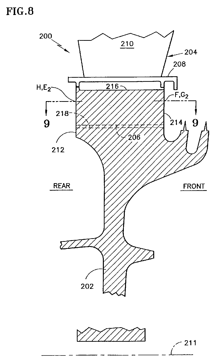
- Fig. 8 is a sectional view of a rotor assembly, like the sectional view of Fig. 2, but showing a rotor assembly incorporating an alternate embodiment of the present invention.
- Fig. 9 is a simplified sectional view taken along the line 9-9 of Fig. 8.
- Fig. 10 is an isometric view in the direction S of Fig. 9 perpendicular to the rear face of the disk, with the blade removed.
- Figs. 11 and 12 are schematic views in the directions 11-11 and 12-12, respectively, of Fig. 4 showing, for the embodiment of Fig. 8, the disk/blade load transfer interfaces along opposite sides of a blade root slot.
- Referring to Figs. 1 and 2, a gas turbine
engine rotor assembly 100 incorporating an exemplary embodiment of the present invention includes arotor disk 102 and a plurality ofrotor blades 104, only one of which is shown. Each blade comprises aroot 106,platform 108, andairfoil 110. Thedisk 102 has arotational axis 111, arear face 112, afront face 114, and arim 116. A plurality ofblade root slots 118 extends through the rim from the rear face to the front face in a direction D (Fig. 3). Each pair of adjacent slots defines adisk lug 120 therebetween. Theroot 106 of each blade is disposed within a respective one of the slots. - Referring to Fig. 3, each
slot 118 extends in the direction D at an acute angle θ to the direction of thedisk axis 111. Generally, this angle is between about 10º and 30º. In this example θ is 24º and, as best shown in Fig. 4, theblade roots 106 are of the well known "dovetail" shape, although the invention is not limited to use with blades having dovetail roots. The root of each blade has a pair of flat, radially outwardly facingload reaction surfaces surfaces load reaction surfaces - In the prior art, blade roots and disk slots, as well as the load transfer interfaces, are the same length, which is generally the full length, L (Fig. 3), of the slot, as measured in the direction D of the slot. In accordance with the present invention, at least one of the blade root
load reaction surfaces blade root 106, although fully within theslot 118, has oppositely facingend surfaces load transfer interfaces load reaction surfaces blade 104, showing the orientation and position of theblade root 106 relative to theblade platform 108 and the disk front andrear faces - Reference is also made to Figs. 3, 5 and 6 for an understanding of certain of the benefits of the present invention as compared to the prior art. In the present invention, the root
load reaction surfaces load reaction surfaces root end surfaces front faces curves curves load reaction surfaces curves curves - Compare the "prior art"
curves curves - In the foregoing embodiment, the benefits are primarily the result of lowering the weight of the blade by reducing the length of the blade root. That reduces the total load on the disk lugs and corresponding stress levels; and, by having a more balanced load over the length of the root, the stress concentrations are even further reduced. At first glance, it may appear that the reduced reaction load surface areas might negate these benefits; however, the loss of load reaction surface area is not particularly detrimental because the eliminated portions of the prior art reaction surfaces near the ends of the slots (the non-cross-hatched portions of Figs. 5 and 6) were carrying only a relatively small portion of the total load per unit surface area, as compared to the average load per unit surface area over the full length of the slot.
- Although in the foregoing embodiment the blade root end surfaces 126, 128 are perpendicular to the blade root load reaction surfaces 122A, 122B, this is not a requirement. It is preferred, however, that the blade root end surfaces be parallel to each other to maintain symmetry. Thus, a parallelogram cross-sectional shape (in the view of Fig. 3) with the blade root of any length less than the slot length L (in the direction D) may provide a benefit over the prior art by reducing blade weight. Preferably, the angle α is between 0º and θ. Although the blade root end surfaces 126, 128 are preferably parallel, they need not be; and, thus, M does not need to equal N, although at least one of them must be less than L.
- In accordance with another embodiment of the present invention, reference is made to Figs. 8, 9 and 10. The
rotor assembly 200 includes adisk 202 andblades 204, only one of which is shown. The disk axis is designated by thereference numeral 211. The disk has front and rear parallel opposed faces 214, 212 adjacent itsrim 216. The disk also has a plurality of circumferentially spaced apartblade root slots 218 defined by and between disk lugs 220, and extending through the disk rim from thefront face 212 to therear face 214. As in the previous embodiment, theslots 218 are cut at an angle to thedisk axis 211. Eachblade 204 comprises a dovetail-shapedroot 206,platform 208, andairfoil 210. In this embodiment, as is also the case in rotor assemblies of the prior art, the blade roots extend the full length of their respective slots, whereby the root end surfaces 226, 228 are substantially flush with respective end faces 212, 214 of the disk, at least over the radial extent of the root load reaction surfaces. - In accordance with this embodiment of the invention, the
lugs 220 on each side of ablade root 206 each have pockets 300, 302 cut into opposite end faces 212, 214 of the disk at the rim to cut back or remove material that would otherwise form a portion of a slot load reaction surface that engages a blade root load reaction surface. Thus, as shown in Figs. 9, wherein the cross-section through the blade root is shown crosshatched, the rootload reaction surface 222A and the slotload reaction surface 224A both extend from E1 to F. Similarly, the corresponding reaction surfaces 222B and 224B on the other side of the slot extend from G1 to H. Essentially, thepockets gaps lug 220 and what are hereinafter referred to as extensions 308 (having a length from E1 to E2) and 310 (having a length from G1 to G2) of the blade root load reaction surfaces 222A, 222B, respectively. - Figs. 11 and 12 are analogous to Figs. 5 and 6 of the previously described embodiment, and show the
load transfer interfaces curves - Although the invention has been described and illustrated with respect to exemplary embodiments thereof, it should be understood by those skilled in the art that the foregoing and various other changes, omissions and additions may be made without departing from the scope of the invention. For example, gaps similar to the
gaps
Claims (7)
- A rotor assembly comprising:a disk (202) having a rotational axis (211), opposing front and rear surfaces, (214,212) a rim (216), and a plurality of circumferentially spaced apart blade retaining slots (218) extending through said rim (216) from said front disk surface (214) through said rear disk surface (212) in a direction D which forms an angle θ of at least 10º with said disk axis (211), each pair of adjacent slots (218) defining a disk lug (220) therebetween, each of said slots having a first radially inwardly facing slot load reaction surface (224B) extending from said front disk surface (214) in said direction D a distance M on a first of said lugs, and a second radially inwardly facing slot load reaction surface (1224B) extending from said rear disk surface (212) in said direction D a distance N on a second of said lugs adjacent said first lug, each of said slots (218) having a length L from said disk front surface to said disk rear surface in said direction D; anda plurality of blades (204), each having an airfoil (210) and a root (206) integral with said airfoil, said root disposed within a respective one of said slots (218), said root having a radially outwardly facing first root load reaction surface (222A) extending in said direction D a distance M and a radially outwardly facing second root load reaction surface (222B) extending in said direction D a distance N, said first root load reaction surface (222A) adapted to contact said first slot load reaction surface (224B) over said distance M, and said second root load reaction surface (222B) adapted to contact said second slot load reaction surface (224B) over said distance N, wherein said slot length L is greater than at least one of said distances M and N; and wherein:said blade root (206) has oppositely facing end surfaces (226;228) and at least one of said blade root end surfaces (214;216) is substantially in the plane of one of said opposing disk front and rear surfaces (214;216) over the radial extent of said root reaction surfaces (222A;222B), and wherein at least one of said root load reaction surfaces includes an extension (308,310), in the direction D, to said at least one of said root end surfaces (212;214), said slot being spaced from said load reaction surface extension (308) leaving a gap (304;306) therebetween.
- The rotor assembly according to claim 1, wherein one of said blade root end surfaces (228) is substantially in the plane of said disk front surface (214) over the radial extent of said root load reaction surfaces, and the other one of said blade root end surfaces (226) is substantially in the plane of said disk rear surface (212) over the radial extent of said root load reaction surfaces, and wherein each of said root load reaction surfaces includes an extension (308;310), in the direction D, to a respective one of said root end surfaces, said slot being spaced from each of said load reaction surface extensions leaving gaps (304,306) therebetween.
- The rotor assembly according to claim 1 or 2, wherein M equals N.
- The rotor assembly according to claim 1 or 2, wherein the slot length L is greater than both M and N.
- The rotor assembly according to any preceding claim wherein said blade root (206) has oppositely facing end surfaces (226;228) perpendicular to said axial direction.
- The rotor assembly according to any preceding claim wherein said root (206) is a dovetail root.
- A bladed rotor disk including a plurality of spaced apart blade root slots (118;218) extending through the disk (102;202) at an angle to the disk axial direction and having an inward facing load reaction surface (124A,124B;224A,224B) extending over less than the full length of the slot (118;218) in contact with a corresponding outwardly facing load reaction surface (122A,122B; 22A,222B) of a blade root (106;206) disposed within the slot (118;218).
Applications Claiming Priority (2)
| Application Number | Priority Date | Filing Date | Title |
|---|---|---|---|
| US09/746,255 US6439851B1 (en) | 2000-12-21 | 2000-12-21 | Reduced stress rotor blade and disk assembly |
| EP01310608A EP1219782B1 (en) | 2000-12-21 | 2001-12-19 | Bladed rotor assembly |
Related Parent Applications (1)
| Application Number | Title | Priority Date | Filing Date |
|---|---|---|---|
| EP01310608A Division EP1219782B1 (en) | 2000-12-21 | 2001-12-19 | Bladed rotor assembly |
Publications (3)
| Publication Number | Publication Date |
|---|---|
| EP1813771A2 true EP1813771A2 (en) | 2007-08-01 |
| EP1813771A3 EP1813771A3 (en) | 2008-02-20 |
| EP1813771B1 EP1813771B1 (en) | 2009-04-29 |
Family
ID=25000063
Family Applications (2)
| Application Number | Title | Priority Date | Filing Date |
|---|---|---|---|
| EP01310608A Expired - Lifetime EP1219782B1 (en) | 2000-12-21 | 2001-12-19 | Bladed rotor assembly |
| EP07009913A Expired - Lifetime EP1813771B1 (en) | 2000-12-21 | 2001-12-19 | Bladed rotor assembly |
Family Applications Before (1)
| Application Number | Title | Priority Date | Filing Date |
|---|---|---|---|
| EP01310608A Expired - Lifetime EP1219782B1 (en) | 2000-12-21 | 2001-12-19 | Bladed rotor assembly |
Country Status (4)
| Country | Link |
|---|---|
| US (1) | US6439851B1 (en) |
| EP (2) | EP1219782B1 (en) |
| JP (1) | JP4101508B2 (en) |
| DE (2) | DE60128645T2 (en) |
Families Citing this family (33)
| Publication number | Priority date | Publication date | Assignee | Title |
|---|---|---|---|---|
| US6769877B2 (en) * | 2002-10-18 | 2004-08-03 | General Electric Company | Undercut leading edge for compressor blades and related method |
| US7121803B2 (en) * | 2002-12-26 | 2006-10-17 | General Electric Company | Compressor blade with dovetail slotted to reduce stress on the airfoil leading edge |
| US6902376B2 (en) * | 2002-12-26 | 2005-06-07 | General Electric Company | Compressor blade with dovetail slotted to reduce stress on the airfoil leading edge |
| GB0302116D0 (en) * | 2003-01-30 | 2003-03-05 | Rolls Royce Plc | A rotor |
| SE526255C2 (en) * | 2003-03-14 | 2005-08-09 | Sandvik Intellectual Property | Tools and indexable inserts for fine turning of rotationally symmetrical grooves in workpieces |
| US7156621B2 (en) * | 2004-05-14 | 2007-01-02 | Pratt & Whitney Canada Corp. | Blade fixing relief mismatch |
| JP4869616B2 (en) * | 2005-04-01 | 2012-02-08 | 株式会社日立製作所 | Steam turbine blade, steam turbine rotor, steam turbine using the same, and power plant |
| US20060251522A1 (en) * | 2005-05-05 | 2006-11-09 | Matheny Alfred P | Curved blade and vane attachment |
| EP1882084A4 (en) * | 2005-05-12 | 2013-06-26 | Gen Electric | Blade/disk dovetail backcut for blade/disk stress reduction (9fa+e, stage 2) |
| GB2440862B (en) * | 2005-05-12 | 2010-09-29 | Gen Electric | Black/disk dovetail backcut for blade/disk stress reduction (6fa and 6fa+e stage 1) |
| JP4870754B2 (en) | 2005-05-12 | 2012-02-08 | ゼネラル・エレクトリック・カンパニイ | Rotor blade / disc dovetail backcut to reduce stress on rotor blade / disk (7FA + e, 2nd stage) |
| WO2006124617A2 (en) * | 2005-05-12 | 2006-11-23 | General Electric Company | BLADE/DISK DOVETAIL BACKCUT FOR BLADE/DISK STRESS REDUCTION (9FA+e, STAGE 1) |
| WO2006124615A1 (en) * | 2005-05-16 | 2006-11-23 | General Electric Company | Blade/disk dovetail backcut for blade/disk stress reduction (7fa+e, stage 1) |
| GB0521242D0 (en) * | 2005-10-19 | 2005-11-23 | Rolls Royce Plc | A blade mounting |
| US7476085B2 (en) * | 2006-05-12 | 2009-01-13 | General Electric Company | Blade/disk dovetail backcut for blade/disk stress reduction (6FA+E, stage2) |
| EP2019913A4 (en) * | 2006-05-12 | 2011-06-01 | Gen Electric | BLADE/DISK DOVETAIL BACKCUT FOR BLADE/DISK STRESS REDUCTION (6FA+e, STAGE 2) |
| FR2900989B1 (en) * | 2006-05-12 | 2008-07-11 | Snecma Sa | AIRCRAFT ENGINE COMPRESSOR ASSEMBLY COMPRISING AUBES WITH FOOT HAMMER ATTACHMENT |
| US20080101937A1 (en) * | 2006-10-26 | 2008-05-01 | General Electric | Blade/disk dovetail backcut for blade/disk stress reduction (9FA, stage 1) |
| US20080101939A1 (en) * | 2006-10-26 | 2008-05-01 | General Electric | Blade/disk dovetail backcut for blade/disk stress reduction (7FA, stage 2) |
| US20080101938A1 (en) * | 2006-10-26 | 2008-05-01 | General Electric | Blade/disk dovetail backcut for blade/disk stress reduction (7FA, stage 1) |
| US7927069B2 (en) * | 2006-11-13 | 2011-04-19 | United Technologies Corporation | Hoop seal with partial slot geometry |
| US20130333173A1 (en) * | 2012-06-15 | 2013-12-19 | Mitsubishi Heavy Industries, Ltd. | Blade root spring insertion jig and insertion method of blade root spring |
| US9366145B2 (en) * | 2012-08-24 | 2016-06-14 | United Technologies Corporation | Turbine engine rotor assembly |
| US9739159B2 (en) | 2013-10-09 | 2017-08-22 | General Electric Company | Method and system for relieving turbine rotor blade dovetail stress |
| JP5726261B2 (en) * | 2013-10-18 | 2015-05-27 | 三菱重工業株式会社 | Rotor blade for axial compressor and axial compressor |
| US10260350B2 (en) * | 2014-09-05 | 2019-04-16 | United Technologies Corporation | Gas turbine engine airfoil structure |
| FR3026429B1 (en) * | 2014-09-30 | 2016-12-09 | Snecma | MOBILE TURBINE DRAWING, COMPRISING AN ERGOT ENGAGING A ROTOR DISK BLOCKING DETAIL |
| US9896947B2 (en) * | 2014-12-15 | 2018-02-20 | United Technologies Corporation | Turbine airfoil attachment with multi-radial serration profile |
| EP3034798B1 (en) * | 2014-12-18 | 2018-03-07 | Ansaldo Energia Switzerland AG | Gas turbine vane |
| US10371163B2 (en) | 2016-02-02 | 2019-08-06 | General Electric Company | Load absorption systems and methods |
| US20170356297A1 (en) * | 2016-06-13 | 2017-12-14 | General Electric Company | Lockwire Tab Backcut For Blade Stress Reduction (9E.04) |
| KR102176954B1 (en) * | 2017-09-14 | 2020-11-10 | 두산중공업 주식회사 | Compressor rotor disk for gas turbine |
| USD1072007S1 (en) | 2024-05-21 | 2025-04-22 | Brinkman Products, Inc. | Work holding device |
Family Cites Families (11)
| Publication number | Priority date | Publication date | Assignee | Title |
|---|---|---|---|---|
| US2807436A (en) * | 1952-03-25 | 1957-09-24 | Gen Motors Corp | Turbine wheel and bucket assembly |
| DE1070335B (en) * | 1955-06-24 | |||
| AT287741B (en) * | 1968-10-28 | 1971-02-10 | Elin Union Ag | Securing of blades held in profiled axial grooves of a turbine rotor against axial displacement |
| US4169694A (en) * | 1977-07-20 | 1979-10-02 | Electric Power Research Institute, Inc. | Ceramic rotor blade having root with double curvature |
| JPS57186004A (en) * | 1981-05-13 | 1982-11-16 | Hitachi Ltd | Structure of rotor for turbo-machine |
| US4480957A (en) * | 1983-04-14 | 1984-11-06 | General Electric Company | Dynamic response modification and stress reduction in dovetail and blade assembly |
| US5259728A (en) * | 1992-05-08 | 1993-11-09 | General Electric Company | Bladed disk assembly |
| FR2725239B1 (en) * | 1994-09-30 | 1996-11-22 | Gec Alsthom Electromec | PROVISION FOR THE SHARPING OF STRESS SPIKES IN THE ANCHORAGE OF A TURBINE BLADE, COMPRISING A ROOT CALLED IN "FOOT-FIR" |
| JP2000512707A (en) * | 1996-06-21 | 2000-09-26 | シーメンス アクチエンゲゼルシヤフト | Rotor of turbine machine having blades mountable in groove and rotor blades |
| DE19705323A1 (en) * | 1997-02-12 | 1998-08-27 | Siemens Ag | Turbo-machine blade |
| US6183202B1 (en) * | 1999-04-30 | 2001-02-06 | General Electric Company | Stress relieved blade support |
-
2000
- 2000-12-21 US US09/746,255 patent/US6439851B1/en not_active Expired - Lifetime
-
2001
- 2001-12-19 DE DE60128645T patent/DE60128645T2/en not_active Expired - Lifetime
- 2001-12-19 DE DE60138579T patent/DE60138579D1/en not_active Expired - Lifetime
- 2001-12-19 EP EP01310608A patent/EP1219782B1/en not_active Expired - Lifetime
- 2001-12-19 EP EP07009913A patent/EP1813771B1/en not_active Expired - Lifetime
- 2001-12-20 JP JP2001386954A patent/JP4101508B2/en not_active Expired - Fee Related
Also Published As
| Publication number | Publication date |
|---|---|
| DE60128645T2 (en) | 2007-09-20 |
| JP4101508B2 (en) | 2008-06-18 |
| EP1813771B1 (en) | 2009-04-29 |
| EP1219782A2 (en) | 2002-07-03 |
| US20020081205A1 (en) | 2002-06-27 |
| EP1219782B1 (en) | 2007-05-30 |
| JP2002201910A (en) | 2002-07-19 |
| EP1219782A3 (en) | 2003-10-08 |
| EP1813771A3 (en) | 2008-02-20 |
| DE60138579D1 (en) | 2009-06-10 |
| US6439851B1 (en) | 2002-08-27 |
| DE60128645D1 (en) | 2007-07-12 |
Similar Documents
| Publication | Publication Date | Title |
|---|---|---|
| EP1813771B1 (en) | Bladed rotor assembly | |
| US4595340A (en) | Gas turbine bladed disk assembly | |
| US5474421A (en) | Turbomachine rotor | |
| CN100359134C (en) | Turbine blades with notches on roots | |
| US4460315A (en) | Turbomachine rotor assembly | |
| JP4512377B2 (en) | Blade shim snap fit | |
| EP1496202A1 (en) | Airfoil shape for a turbine bucket | |
| EP0799972B1 (en) | A root attachment for a Turbomachine blade | |
| EP1751399B1 (en) | Fan blade fixing with a load relief play | |
| GB2038959A (en) | Turbomachinery blade retaining assembly | |
| US5593282A (en) | Turbomachine rotor construction including a serrated root section and a rounded terminal portion on a blade root, especially for an axial-flow turbine of a gas turbine engine | |
| EP4130430B1 (en) | Integrated bladed rotor | |
| US5271718A (en) | Lightweight platform blade | |
| US7419361B1 (en) | Blade/disk dovetail backcut for blade/disk stress reduction (7FA+e, stage 2) | |
| US9739159B2 (en) | Method and system for relieving turbine rotor blade dovetail stress | |
| GB2295861A (en) | Split disc gas turbine engine blade support | |
| US7476083B2 (en) | Blade/disk dovetail backcut for blade/disk stress reduction (7FA+e, stage 1) | |
| US7419362B2 (en) | Blade/disk dovetail backcut for blade/disk stress reduction (9FA+e, stage 1) | |
| US7476084B1 (en) | Blade/disk dovetail backcut for blade/disk stress reduction (6FA and 6FA+e, stage 1) | |
| US20060275130A1 (en) | Blade/disk dovetail backcut for blade/disk stress reduction (9FA+e, stage 2) | |
| GB2162588A (en) | Gas turbine blades | |
| CN1039873A (en) | The side-entry grooves that is used for mounting turbine blades | |
| JPS595806A (en) | Axial flow turbine rotor |
Legal Events
| Date | Code | Title | Description |
|---|---|---|---|
| PUAI | Public reference made under article 153(3) epc to a published international application that has entered the european phase |
Free format text: ORIGINAL CODE: 0009012 |
|
| AC | Divisional application: reference to earlier application |
Ref document number: 1219782 Country of ref document: EP Kind code of ref document: P |
|
| AK | Designated contracting states |
Kind code of ref document: A2 Designated state(s): DE FR GB |
|
| PUAL | Search report despatched |
Free format text: ORIGINAL CODE: 0009013 |
|
| AK | Designated contracting states |
Kind code of ref document: A3 Designated state(s): DE FR GB |
|
| RIC1 | Information provided on ipc code assigned before grant |
Ipc: F01D 5/30 20060101AFI20080115BHEP Ipc: F01D 5/14 20060101ALI20080115BHEP |
|
| 17P | Request for examination filed |
Effective date: 20080328 |
|
| 17Q | First examination report despatched |
Effective date: 20080508 |
|
| AKX | Designation fees paid |
Designated state(s): DE GB |
|
| GRAP | Despatch of communication of intention to grant a patent |
Free format text: ORIGINAL CODE: EPIDOSNIGR1 |
|
| GRAP | Despatch of communication of intention to grant a patent |
Free format text: ORIGINAL CODE: EPIDOSNIGR1 |
|
| GRAS | Grant fee paid |
Free format text: ORIGINAL CODE: EPIDOSNIGR3 |
|
| GRAA | (expected) grant |
Free format text: ORIGINAL CODE: 0009210 |
|
| AC | Divisional application: reference to earlier application |
Ref document number: 1219782 Country of ref document: EP Kind code of ref document: P |
|
| AK | Designated contracting states |
Kind code of ref document: B1 Designated state(s): DE GB |
|
| REG | Reference to a national code |
Ref country code: GB Ref legal event code: FG4D |
|
| REF | Corresponds to: |
Ref document number: 60138579 Country of ref document: DE Date of ref document: 20090610 Kind code of ref document: P |
|
| PLBE | No opposition filed within time limit |
Free format text: ORIGINAL CODE: 0009261 |
|
| STAA | Information on the status of an ep patent application or granted ep patent |
Free format text: STATUS: NO OPPOSITION FILED WITHIN TIME LIMIT |
|
| 26N | No opposition filed |
Effective date: 20100201 |
|
| REG | Reference to a national code |
Ref country code: DE Ref legal event code: R082 Ref document number: 60138579 Country of ref document: DE Representative=s name: SCHMITT-NILSON SCHRAUD WAIBEL WOHLFROM PATENTA, DE |
|
| REG | Reference to a national code |
Ref country code: DE Ref legal event code: R082 Ref document number: 60138579 Country of ref document: DE Representative=s name: SCHMITT-NILSON SCHRAUD WAIBEL WOHLFROM PATENTA, DE Ref country code: DE Ref legal event code: R081 Ref document number: 60138579 Country of ref document: DE Owner name: UNITED TECHNOLOGIES CORP. (N.D.GES.D. STAATES , US Free format text: FORMER OWNER: UNITED TECHNOLOGIES CORPORATION, HARTFORD, CONN., US |
|
| PGFP | Annual fee paid to national office [announced via postgrant information from national office to epo] |
Ref country code: DE Payment date: 20191119 Year of fee payment: 19 |
|
| PGFP | Annual fee paid to national office [announced via postgrant information from national office to epo] |
Ref country code: GB Payment date: 20191122 Year of fee payment: 19 |
|
| REG | Reference to a national code |
Ref country code: DE Ref legal event code: R119 Ref document number: 60138579 Country of ref document: DE |
|
| GBPC | Gb: european patent ceased through non-payment of renewal fee |
Effective date: 20201219 |
|
| PG25 | Lapsed in a contracting state [announced via postgrant information from national office to epo] |
Ref country code: GB Free format text: LAPSE BECAUSE OF NON-PAYMENT OF DUE FEES Effective date: 20201219 Ref country code: DE Free format text: LAPSE BECAUSE OF NON-PAYMENT OF DUE FEES Effective date: 20210701 |