EP1813744A2 - Sicherheitstürvorrichtung - Google Patents
Sicherheitstürvorrichtung Download PDFInfo
- Publication number
- EP1813744A2 EP1813744A2 EP20070250369 EP07250369A EP1813744A2 EP 1813744 A2 EP1813744 A2 EP 1813744A2 EP 20070250369 EP20070250369 EP 20070250369 EP 07250369 A EP07250369 A EP 07250369A EP 1813744 A2 EP1813744 A2 EP 1813744A2
- Authority
- EP
- European Patent Office
- Prior art keywords
- door
- alarm unit
- electronic lock
- alarm
- security
- Prior art date
- Legal status (The legal status is an assumption and is not a legal conclusion. Google has not performed a legal analysis and makes no representation as to the accuracy of the status listed.)
- Withdrawn
Links
- 230000033001 locomotion Effects 0.000 claims description 7
- 230000000994 depressogenic effect Effects 0.000 claims description 3
- 238000012544 monitoring process Methods 0.000 abstract description 38
- 230000000712 assembly Effects 0.000 description 4
- 238000000429 assembly Methods 0.000 description 4
- 229910052751 metal Inorganic materials 0.000 description 4
- 239000002184 metal Substances 0.000 description 4
- 238000009434 installation Methods 0.000 description 3
- 238000004519 manufacturing process Methods 0.000 description 3
- 230000007246 mechanism Effects 0.000 description 2
- 238000009418 renovation Methods 0.000 description 2
- WHXSMMKQMYFTQS-UHFFFAOYSA-N Lithium Chemical compound [Li] WHXSMMKQMYFTQS-UHFFFAOYSA-N 0.000 description 1
- 238000013459 approach Methods 0.000 description 1
- 230000005540 biological transmission Effects 0.000 description 1
- 238000004891 communication Methods 0.000 description 1
- 230000000881 depressing effect Effects 0.000 description 1
- 238000013461 design Methods 0.000 description 1
- 230000000694 effects Effects 0.000 description 1
- 239000003292 glue Substances 0.000 description 1
- 238000003780 insertion Methods 0.000 description 1
- 230000037431 insertion Effects 0.000 description 1
- 229910052744 lithium Inorganic materials 0.000 description 1
- 230000000717 retained effect Effects 0.000 description 1
- 230000000007 visual effect Effects 0.000 description 1
Images


Classifications
-
- E—FIXED CONSTRUCTIONS
- E05—LOCKS; KEYS; WINDOW OR DOOR FITTINGS; SAFES
- E05B—LOCKS; ACCESSORIES THEREFOR; HANDCUFFS
- E05B47/00—Operating or controlling locks or other fastening devices by electric or magnetic means
- E05B47/06—Controlling mechanically-operated bolts by electro-magnetically-operated detents
- E05B47/0657—Controlling mechanically-operated bolts by electro-magnetically-operated detents by locking the handle, spindle, follower or the like
-
- E—FIXED CONSTRUCTIONS
- E05—LOCKS; KEYS; WINDOW OR DOOR FITTINGS; SAFES
- E05B—LOCKS; ACCESSORIES THEREFOR; HANDCUFFS
- E05B45/00—Alarm locks
- E05B45/06—Electric alarm locks
-
- E—FIXED CONSTRUCTIONS
- E06—DOORS, WINDOWS, SHUTTERS, OR ROLLER BLINDS IN GENERAL; LADDERS
- E06B—FIXED OR MOVABLE CLOSURES FOR OPENINGS IN BUILDINGS, VEHICLES, FENCES OR LIKE ENCLOSURES IN GENERAL, e.g. DOORS, WINDOWS, BLINDS, GATES
- E06B5/00—Doors, windows, or like closures for special purposes; Border constructions therefor
- E06B5/10—Doors, windows, or like closures for special purposes; Border constructions therefor for protection against air-raid or other war-like action; for other protective purposes
- E06B5/11—Doors, windows, or like closures for special purposes; Border constructions therefor for protection against air-raid or other war-like action; for other protective purposes against burglary
-
- G—PHYSICS
- G07—CHECKING-DEVICES
- G07C—TIME OR ATTENDANCE REGISTERS; REGISTERING OR INDICATING THE WORKING OF MACHINES; GENERATING RANDOM NUMBERS; VOTING OR LOTTERY APPARATUS; ARRANGEMENTS, SYSTEMS OR APPARATUS FOR CHECKING NOT PROVIDED FOR ELSEWHERE
- G07C9/00—Individual registration on entry or exit
- G07C9/00174—Electronically operated locks; Circuits therefor; Nonmechanical keys therefor, e.g. passive or active electrical keys or other data carriers without mechanical keys
- G07C9/00658—Electronically operated locks; Circuits therefor; Nonmechanical keys therefor, e.g. passive or active electrical keys or other data carriers without mechanical keys operated by passive electrical keys
- G07C9/00674—Electronically operated locks; Circuits therefor; Nonmechanical keys therefor, e.g. passive or active electrical keys or other data carriers without mechanical keys operated by passive electrical keys with switch-buttons
- G07C9/0069—Electronically operated locks; Circuits therefor; Nonmechanical keys therefor, e.g. passive or active electrical keys or other data carriers without mechanical keys operated by passive electrical keys with switch-buttons actuated in a predetermined sequence
-
- E—FIXED CONSTRUCTIONS
- E05—LOCKS; KEYS; WINDOW OR DOOR FITTINGS; SAFES
- E05B—LOCKS; ACCESSORIES THEREFOR; HANDCUFFS
- E05B47/00—Operating or controlling locks or other fastening devices by electric or magnetic means
- E05B2047/0048—Circuits, feeding, monitoring
- E05B2047/0065—Saving energy
-
- E—FIXED CONSTRUCTIONS
- E06—DOORS, WINDOWS, SHUTTERS, OR ROLLER BLINDS IN GENERAL; LADDERS
- E06B—FIXED OR MOVABLE CLOSURES FOR OPENINGS IN BUILDINGS, VEHICLES, FENCES OR LIKE ENCLOSURES IN GENERAL, e.g. DOORS, WINDOWS, BLINDS, GATES
- E06B1/00—Border constructions of openings in walls, floors, or ceilings; Frames to be rigidly mounted in such openings
- E06B1/56—Fastening frames to the border of openings or to similar contiguous frames
- E06B1/60—Fastening frames to the border of openings or to similar contiguous frames by mechanical means, e.g. anchoring means
- E06B1/6092—Fastening door frames to the floor or ceiling; Jamb feet; Cross members uniting the jamb feet
-
- G—PHYSICS
- G07—CHECKING-DEVICES
- G07C—TIME OR ATTENDANCE REGISTERS; REGISTERING OR INDICATING THE WORKING OF MACHINES; GENERATING RANDOM NUMBERS; VOTING OR LOTTERY APPARATUS; ARRANGEMENTS, SYSTEMS OR APPARATUS FOR CHECKING NOT PROVIDED FOR ELSEWHERE
- G07C9/00—Individual registration on entry or exit
- G07C9/00174—Electronically operated locks; Circuits therefor; Nonmechanical keys therefor, e.g. passive or active electrical keys or other data carriers without mechanical keys
- G07C2009/00634—Power supply for the lock
-
- Y—GENERAL TAGGING OF NEW TECHNOLOGICAL DEVELOPMENTS; GENERAL TAGGING OF CROSS-SECTIONAL TECHNOLOGIES SPANNING OVER SEVERAL SECTIONS OF THE IPC; TECHNICAL SUBJECTS COVERED BY FORMER USPC CROSS-REFERENCE ART COLLECTIONS [XRACs] AND DIGESTS
- Y10—TECHNICAL SUBJECTS COVERED BY FORMER USPC
- Y10T—TECHNICAL SUBJECTS COVERED BY FORMER US CLASSIFICATION
- Y10T70/00—Locks
- Y10T70/70—Operating mechanism
- Y10T70/7006—Predetermined time interval controlled
- Y10T70/7028—Electric
Definitions
- the present invention relates to a security door apparatus typically use in vacant properties and similar situations where a property is left unattended for substantial period of time.
- a rudimentary way of covering an entrance way is to fasten a wooden board over the outside of the window or door, but this is relatively easy to remove by someone determined to enter the building.
- a security door assembly which is secured over an existing entrance way in to a building is described in EP 0 141 623 .
- the assembly comprises a door hingedly mounted in a frame with the assembly braced in the entrance way.
- the assembly is provided with locks which prevent the door from moving about its hinges from a position located in the doorframe.
- a particularly advanced security door apparatus is known from EP-A-0 728 887 , though if all possible features of this door are incorporated in a production door, the door becomes expensive to manufacture.
- the security door assemblies are normally temporarily installed on a building, as mentioned above during renovation or building works.
- the known door assemblies incorporate mortise locks to secure the door in the door frame because mortise locks provide straightforward fitting and a reasonable degree of security.
- Mortise locks do, however, have a number of disadvantages. Firstly, the keyhole allows the possibility that the lock can be picked. In order to decrease the likelihood of this occurring, complex and expensive locking mechanisms are often used and some manufacturers only use their own locks on their doors. The use of such complex locks in itself can be disadvantageous because this requires the change of complete locking mechanisms when a door is moved from site to site.
- a particular manufacturer/source is likely to have many thousand doors in circulation at any time, with many thousands of people having keys to one or more of the doors.
- the above factors mean that there is a likelihood that some people may have the keys to a door which they are not authorised to enter.
- mortise locks are prone to vandals causing damage to the locks by inserting glue into the keyhole, or by trying to force the locks. It is known to put sliding covers in the keyhole to prevent such abuse, but this does not entirely overcome the problem.
- Electronic locks are often used in security doors as electronic locks do not require several physical keys in existence for a particular door.
- temporary security doors do not normally have a permanent power supply and so the power supply has to be contained with the security door apparatus. Yet this can pose a problem as the security doors may remain in place for several months or even years and the power supply must not fail over this period.
- the present invention seeks to provide a security door apparatus which is secure whilst being simple to manufacture and reliable in operation.
- a security door apparatus including an electronic lock powered by an internal power supply, the electronic lock having a keypad for input of a code for unlocking the electronic lock, wherein the electronic lock in only powered for a predetermined period after a switch is activated by pressing.
- the intermittent powering of the electronic lock greatly increases the life of the internal power supply, yet may be implemented in a mechanically simple fashion and so does not greatly add to the cost or complexity of the door apparatus.
- the switch can be a key on the keypad or could a separate button for example disguised as a screw fixing the keypad.
- the switch must be depressed to power the electronic lock and in some cases the electronic lock is only powered whilst the switch remains in said activated position so absolutely minimising the time the circuitry is powered.
- the electronic lock prevents movement of a door opener to an open position when in the electronic lock is in a locked position.
- the electronic lock is used to hold a mechanical door opener.
- a further code must be entered into the keypad after the door opener is moved to said open position to disarm an alarm unit.
- the alarm unit will often be monitored and if an unauthorised person attempts to enter the building, the alarm unit can make appropriate notifications even if the unauthorised person manages to physically open the security door apparatus.
- a security door It is known for a security door to have an alarm unit associated therewith.
- the alarm unit may be monitored by a remote monitoring station often by a telephone connection. It is preferred in the present invention for the alarm unit to be armed (i.e. set to monitoring status) by the action of a door opener, e.g. a handle, moving to the closed position.
- a door opener e.g. a handle
- This can be either an automatic function of the door apparatus or may require the person exiting the door to positively move the opener to a closed position. This feature may be used in any door with an alarm unit associated therewith.
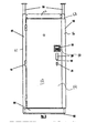
- Figs. 7, 8 and 9 show a embodiments of security door apparatus 10 for mounting exteriorly to a dwelling or other building entrance.
- the door apparatus 10 comprises a door frame 60 on which is hingedly mounted a door 12. Normally, the door frame 60 will be mounted in an existing doorway of the dwelling braced between the door jamb, the threshold and the lintel of the entrance way, or affixed to the existing frame.
- the door 12 is mounted to the door frame 60 on hinges 15 to move hingedly between an open position where the exterior surface of the door 12 is not aligned with the exterior surface of the frame 60 and a closed position where the exterior surface of the door 12 and the frame 60 are substantially coplanar. In the closed position, the door frame 60 prevents any substantial vertical, horizontal, or rotational movement of the door 12 in the door frame 60.
- the door apparatus 10 is kept vertically in place, by means of an expanding threshold 65 and telescopic legs 70 which may be as described in EP-A- 0 728 887 the disclosure of which is hereby incorporated by reference..
- the door frame 60 comprises an upright hinged side member 61 joined at the top to one end of a top frame member 62 which joined at the other end to a lock side member 63.
- the two side members 61, 63 are joined at the base by bottom frame member 64 to define a door opening.
- a U-shaped member 16 is attached on the lock side of the main door panel 14 to enclose that side member 63 of the door frame. This is to protect the door assembly from forced entry by insertion of levers into the gap between the door frame 60 and the door 12.
- the door 12 comprises a main door panel 14 with inwardly extending flanges.
- the door panel 14 is the same size as the opening in the door frame 60.
- the door is hinged on one side and has a door member 16 fixed on the other side of the door panel 14.
- the door member comprises a U-shaped section extending along the whole side of the door panel 14. One side of the U-shaped section is in face to face contact with the inwardly extending flange of the door panel 14. When the door is in the closed position, the door member 16 extends around the side member 63 of the door frame 60 with the rear frame panel.
- the hinges 15 are mounted with the pivot extending outwardly from the exterior surface of the door frame 60.
- the door 12 cannot be removed from the door frame 60 because of members (not shown) extending from the inner flange of the door 12 into associated openings in the opposed surface of the door frame 60 and members (not shown) extending from the inner flange of the door frame 60 into associated openings in the opposed surface of the door frame inner flange.
- Alternative securing means could also be used.
- the door apparatus 10 is fitted with security locks to prevent the door 12 moving from the closed position to the open position.
- the locks may take the form of normal mortice locks (as shown in Fig. 2) with or without disguised keyways or other similar anti-vandal devices.
- the door is fitted with the multiple lock security arrangement.
- the door 12 has a handle 20 mounted on the exterior surface of the door 12.
- Handle 20 is used as the primary door opener and moves between an the open position where the door 12 can swing on hinges 15 and a closed position where the door is retained in the door frame 60.
- Opening 21 is a mortise lock key hole, but may in fact be simple hole with no lock attached as this can the act as a point that a vandal can attack without impinging on the function of the door apparatus.
- a microswitch key pad (not shown) is mounted on the rear surface of the door panel 14.
- a metal plate is mounted on the exterior surface of the door panel 14.
- the metal plate has a finger pad 19 on the front surface thereof.
- the finger pad 19 may be disguised as a changeable street number of the door apparatus.
- the finger pad 19 comprises a plate with fingers 46 cut into the surface thereof. Depression of any finger 46 presses against an associated actuating member (not shown) which extends through the door panel 14.
- the microswitch key pad could, of course, be located on the exterior surface of the door in an armoured case, in a conventional manner. However, this is considered to be less secure than the illustrated embodiment because the microswitch keypad is more vulnerable to vandalism or other unauthorised tampering.
- the microswitch key pad operates the electric lock (not shown) if the correct combination is input into the key pad 45 so that the electric lock moves between a locked an unlocked position. In the locked position the electric lock prevents door opener 20 from moving between the open and closed positions, whereas such movement is permitted when the electric lock is in the unlocked position.
- the door apparatus also has an alarm unit 30 fitted to the interior thereof.
- the alarm unit 30 is used to detect unauthorised entry through the door 12, or attempted unauthorised entry.
- the electronic locks and alarm unit 30 are powered from an internal power source (not shown). Normally, the power supply is disconnected from the electronic lock and the alarm unit in order to preserve the operation time over which the internal power source will remain usable.
- the power supply is connected to the electronic lock. If the correct unlock code is entered, the electronic lock releases handle 20 to be movable into its open position for a preset duration, e.g. 30 seconds.
- a further alarm code must be input through the finger pad 19 to disarm the alarm unit 30. If the alarm code is not appropriately entered the alarm will sound as described in more detail below. If the alarm code is entered an authorised entry can be made.
- the door 14 After passing through the doorway, the door 14 is then moved back into line with the door frame 60 by the authorised person and held on a simple catch that is openable from the inside only so that a level of security remains for the door apparatus 10 even while authorised people are inside the door.
- the catch is designed to prevent the handle 20 from moving back to its closed position whilst the catch is holding the door.
- the alarm unit 30 is shown as a monitored alarm unit which is arranged so that the alarm unit 30 can contact a monitoring station by means of a telephone connection.
- the alarm unit 30 has a build in wireless connection (e.g. a GSM connection).
- the alarm unit 30 has a motion sensor in the form of an infrared sensor mounted thereon to detect movement whilst the alarm unit is powered.
- the alarm unit 30 is not powered from the internal power supply in order to maximise the length of usable service of the power supply.
- the alarm unit 30 sends a call to say that a seemingly authorised entry has occurred. If powered, but the appropriate codes are not input, the alarm units send a call to say an unauthorised entry has been attempted. This may be set in such a way that the person trying to enter will be given a reasonable amount to enter the appropriate codes and/or be given a number of trials to input the appropriate codes before the unauthorised entry alarm call is made.
- the internal power supply is then disconnected form the alarm unit 30 and the electronic lock.
- the power supply is re-connected when the person release the simple catch to leave the property.
- the handle 20 When the person leaves the property, the handle 20 is moved back to the closed position which action automatically arms the alarm, and the alarm unit 30 contacts the monitoring station to say that the alarm unit 30 is again armed.
- the alarm unit 30 and the electronic lock may be permanently powered, for instance in circumstances where the internal power supply can be routinely recharged due to the frequency of access to the property or where there is a permanent power supply available to effect permanent recharging.
- the alarm unit 30 can be set to contact the monitoring station whenever the internal power supply is low or there is any interruption or unexpected event occurring with the power supply.
- the alarm unit 30 does not have to be used in connection with an electronic lock, but may be used e.g. with a simple door apparatus with just a mortise lock as shown in Fig. 2. Unlocking the mortise lock then dis-arms the alarm unit 30 and locking it arms the alarm unit 30.
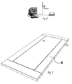
- Fig. 6 shows a typical alarm unit 30, which can be fitted to a temporary or permanent structure such as a door 12 (shown in Figs., 8 or 9).
- the alarm unit 30 shown may have a strong plastic or metal case. If made from plastic the unit will weigh about 1.5kg and when made from metal will weigh about 4.0kg. Inside the case, not shown, the alarm circuitry and GSM transmitter will be located. The system is powered by a long duration Lithium cell which is designed to hold a charge for at least five years but can output the charge at relatively high levels.
- the alarm unit 30 will be programmed to contact the monitoring station 20 when unauthorised entry is attempted or affected on the door 12.
- the alarm unit 30 will also contact the monitoring station when the alarm is armed (door 12 closed and locked), disarmed (door 12 opened by authorised entry e.g. with appropriate code), when the alarm unit 30 has a low battery and periodically (e.g. every 10 days) to show the monitoring unit that the particular alarm unit 10 is functioning.
- the door 12 may be provided with electronic and/or key operated locks.
- the electronic locks will normally be operated through a keypad where the correct code needs to be entered to open the lock.
- the alarm unit 10 may also be programmed to operate an electronic lock on the door. In this way, where there a several doors in operation and, for example, several engineers or other outside contractors need access to various properties over time, there is a security risk in allowing all of these people have door entry codes.
- the present invention can reduce the security risk, by the contractors each being given an alarm contact code.
- the alarm code is input into the alarm unit via the normal door 12 keypad.
- the alarm unit 30 contacts the monitoring station 20. At the monitoring station, details are kept of properties the contractors are meant accessing at any time. Often, the contractor will also have to contact the monitoring station separately by telephone to verify this information. If cleared, the alarm unit 30 can be used to unlock the door 12.
- the alarm units 30 may be stand alone units or may be permanently mounted on a door 12 or other structure.
- the alarm units 30 may detect an alarm state by means of infra red sensors, incorrect codes being entered on an entry panel, breaking of an electrical or visual circuit or any other means as is common or known in the field of alarms.
- the size and appearance of the alarm unit 30 will vary depending upon what types of alarm states are being monitored.
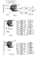
- Figs. 1 to 5 show different embodiments of monitoring stations 20A to 20E according which can be used in conjunction with alarm unit 30 in the present invention.
- the same number is used in the different Figures to illustrate a similar part.
- All types of telephone network now provide basic caller identification, such a telephone number when a call is directed to its recipient. This information is provided before the call is actually answered.
- the alarm unit 30 e.g. as shown in Fig. 6) can contact the monitoring station 20 via GSM modems, ISDN terminal adapters or modems on a PSTN telephone line. It is preferred to use a GSM or other mobile connection for a variety of reasons. Firstly, this allows the alarm unit 30 to be easily portable in temporary or non-fixed (e.g.
- SIM cards used in such mobile networks allows for a variety of numbers to be stored for dialling and so allows facilitates simple implementation of the invention. It is also much more difficult to put an alarm out of communication with the monitoring station when there are no fixed phone lines.
- Fig. 1 shows monitoring station 20A.
- This uses a personal computer 22.
- a call is received from the alarm unit, but this is not answered though the particular identification of the alarm unit that has called the monitoring station 20A is logged.
- the monitoring station records details of this call on the computer 22 such as time and alarm unit 30 identification.
- the monitoring station 20A will transmit information if appropriate via the GSM lines 24A, 24B.
- the first GSM line 24A transmits a voice message that a particular event has occurred at the relevant alarm unit 30. This transmission may be to a security company, the police or other designated recipient.
- Line 24B is used to transmit a Short Message Service (SMS) message to an intended recipient.
- SMS Short Message Service
- Monitoring station 20B is a more complex unit, which has five input lines 26A - 26E and three output lines 24A - 24C.
- Line 26A receives the alarm signals.
- Line 26B receives calls that an alarm unit 30 is armed (i.e. set for surveillance) and line 26C receives calls on disarming of an alarm unit 30.
- Line 22D receives calls that each alarm unit 30 periodically is set to make to ensure that the alarm unit 30 is functioning correctly.
- Line 26E receives calls when an alarm unit 30 has a low battery or an interrupted power supply. The computer 22 will be set to log all of these calls, though of course none of the incoming calls will be answered.
- each alarm unit 30 It will further be set to transmit information about the change in status of each alarm unit 30 that is being monitored via one or more of the three output lines 24A, 24B and 24C. Normally all alarm notifications will be immediately further relayed as with monitoring station 20A.
- monitoring station 22B for example, the owners of the properties being monitored may wish to receive an SMS message each time a door is disarmed or when a low battery is detected.
- This monitoring unit is suitable for up to about 2500 alarm units 30, but further monitoring units 20B can be used if further alarm units 30 are to be monitored.
- FIG. 3 shows a monitoring station 20C that is normally used in conjunction with a monitoring station 20A to provide the functionality of monitoring unit 20B.
- Units 20A, 20C do not have to be located physically together.
- Fig. 4 shows a monitoring unit 20D that has a single GSM input line and a single GSM output line.
- Fig. 5 shows a monitoring station 20E, which is, for example, used to receive calls from monitoring unit 20A via line 24A. Monitoring unit 24A where data is further recorded as soon as an alarm occurs.
- the alarm unit 30 is particularly suited for installation on temporary security doors, it can also be used in a wide range of other places. It could be fitted to boats, cars or other vehicles. It could be included as part of a permanent building alarm or even as part of an item such as a statue.
- the present invention relates to a security door apparatus where electric and electronic parts thereof are powered an internal power supply and the door incorporates enhanced power saving features which may be implemented in simple cost effective fashion.
- the invention may also relate to the alarm units and monitoring stations for security purposes.
Landscapes
- Physics & Mathematics (AREA)
- General Physics & Mathematics (AREA)
- Engineering & Computer Science (AREA)
- Civil Engineering (AREA)
- Structural Engineering (AREA)
- Alarm Systems (AREA)
- Burglar Alarm Systems (AREA)
Applications Claiming Priority (1)
| Application Number | Priority Date | Filing Date | Title |
|---|---|---|---|
| GB0601815A GB0601815D0 (en) | 2006-01-30 | 2006-01-30 | Security door apparatus |
Publications (2)
| Publication Number | Publication Date |
|---|---|
| EP1813744A2 true EP1813744A2 (de) | 2007-08-01 |
| EP1813744A3 EP1813744A3 (de) | 2012-12-19 |
Family
ID=36061104
Family Applications (1)
| Application Number | Title | Priority Date | Filing Date |
|---|---|---|---|
| EP20070250369 Withdrawn EP1813744A3 (de) | 2006-01-30 | 2007-01-30 | Sicherheitstürvorrichtung |
Country Status (3)
| Country | Link |
|---|---|
| US (1) | US20070176775A1 (de) |
| EP (1) | EP1813744A3 (de) |
| GB (1) | GB0601815D0 (de) |
Cited By (15)
| Publication number | Priority date | Publication date | Assignee | Title |
|---|---|---|---|---|
| CN101235700B (zh) * | 2008-03-07 | 2010-11-17 | 广州工程总承包集团有限公司 | 磁力防盗门 |
| CN102561902A (zh) * | 2011-12-30 | 2012-07-11 | 郑清海 | 特种库门 |
| CN103046847A (zh) * | 2013-01-22 | 2013-04-17 | 上海海事大学 | 一种新型智能防盗门 |
| CN103132897A (zh) * | 2011-11-25 | 2013-06-05 | 洛阳天枢光电技术有限公司 | 电动卷闸门无线控制系统 |
| CN103452420A (zh) * | 2013-08-20 | 2013-12-18 | 南昌大学 | 一种防盗安全庭院大门 |
| CN104763296A (zh) * | 2015-04-26 | 2015-07-08 | 姬爱书 | 一种cam技术制造的防盗门 |
| CN104763294A (zh) * | 2015-04-02 | 2015-07-08 | 张晓明 | 一种90厚整体全锁舌防盗门 |
| CN105952337A (zh) * | 2016-07-18 | 2016-09-21 | 安徽状元郎电子科技有限公司 | 一种高压电流防盗门 |
| CN105952333A (zh) * | 2016-04-30 | 2016-09-21 | 安徽硕尼信息科技有限公司 | 一种基于物联网的防盗门系统 |
| CN106050087A (zh) * | 2016-08-02 | 2016-10-26 | 常熟市丰盛建筑装潢木业有限公司 | 一种可远程控制的防盗门 |
| CN106121463A (zh) * | 2016-08-12 | 2016-11-16 | 胡玄 | 一种快递智能寄存门及方法 |
| CN107327261A (zh) * | 2017-08-20 | 2017-11-07 | 合肥智贤智能化科技有限公司 | 一种智能化安全门 |
| CN107620542A (zh) * | 2017-09-15 | 2018-01-23 | 卢云峰 | 抽屉式智能保险柜以及该保险柜的设防方法 |
| CN109812202A (zh) * | 2017-11-18 | 2019-05-28 | 重庆宁来科贸有限公司 | 一种用于智能防盗门的装置 |
| CN110656864A (zh) * | 2019-10-23 | 2020-01-07 | 江苏金泰祥内外门业有限公司 | 一种智能家居防盗门 |
Families Citing this family (12)
| Publication number | Priority date | Publication date | Assignee | Title |
|---|---|---|---|---|
| EP2411968A1 (de) * | 2009-03-24 | 2012-02-01 | Free Aktiengesellschaft | Elektronisches kombinationsschloss |
| CN102409906B (zh) * | 2011-08-03 | 2014-02-26 | 深圳市中联创新自控系统有限公司 | 电锁断电自动开锁装置及带有该装置的电锁 |
| US10815695B2 (en) | 2015-04-14 | 2020-10-27 | Hanchett Entry Systems, Inc. | Power controller for a door lock and method of conserving power |
| WO2016191768A1 (en) * | 2015-05-28 | 2016-12-01 | Friday Labs Limited | Apparatus and system for an electronic lock, and methods of use and manufacture thereof |
| CN105971405B (zh) * | 2016-06-15 | 2019-01-08 | 陈家辉 | 一种微型计算机控制插门装置 |
| CN107524389A (zh) * | 2017-08-19 | 2017-12-29 | 合肥智贤智能化科技有限公司 | 一种人性化高效安全防盗门 |
| CN108049777A (zh) * | 2017-12-21 | 2018-05-18 | 安聪聪 | 一种家用智能安全防护门 |
| CN108397107A (zh) * | 2018-03-24 | 2018-08-14 | 佛山市聚成知识产权服务有限公司 | 一种基于互联网的智能防盗监控门 |
| CN109025718B (zh) * | 2018-07-24 | 2019-04-19 | 朱星泽 | 一种可远程收取快递的物联网防盗门及其系统 |
| US11199889B2 (en) * | 2019-02-15 | 2021-12-14 | Carrier Corporation | Bezel interface providing backup power to relay control circuitry |
| CN112562131A (zh) * | 2020-12-04 | 2021-03-26 | 珠海格力电器股份有限公司 | 解锁人员信息记录方法、装置、存储介质及电子设备 |
| CN113482498B (zh) * | 2021-07-28 | 2022-08-09 | 江西志宏安防科技有限公司 | 基于光纤激光器的楼宇安防门禁系统 |
Citations (1)
| Publication number | Priority date | Publication date | Assignee | Title |
|---|---|---|---|---|
| EP0728887A1 (de) * | 1995-02-22 | 1996-08-28 | Vacant Property Security Limited | Versperreinrichtung |
Family Cites Families (12)
| Publication number | Priority date | Publication date | Assignee | Title |
|---|---|---|---|---|
| US5136870A (en) * | 1988-05-11 | 1992-08-11 | Alan K. Uyeda | Dual electronic lock for human passage door |
| US6359547B1 (en) * | 1994-11-15 | 2002-03-19 | William D. Denison | Electronic access control device |
| US5832671A (en) * | 1995-02-22 | 1998-11-10 | Vacant Property Security Limited | Security closure |
| US6374753B1 (en) * | 1995-03-15 | 2002-04-23 | Dan R. Radke, Jr. | Pallet and process for making thereof |
| GB2339822B (en) * | 1996-03-11 | 2000-09-20 | Vacant Property Security Ltd | Security closure |
| DE19652348C2 (de) * | 1996-12-17 | 1998-12-24 | Dorma Gmbh & Co Kg | Sicherheits-Türterminal mit Sicherheits-NOT-AUF-Taster |
| US6580355B1 (en) * | 1999-06-11 | 2003-06-17 | T.K.M. Unlimited, Inc. | Remote door entry system |
| US6374177B1 (en) * | 2000-09-20 | 2002-04-16 | Motorola, Inc. | Method and apparatus for providing navigational services in a wireless communication device |
| US6737962B2 (en) * | 2000-04-26 | 2004-05-18 | Maxxal International, Inc. | Alarm system and kit with event recording |
| FI115355B (fi) * | 2000-06-22 | 2005-04-15 | Icl Invia Oyj | Järjestely suojatun järjestelmän käyttäjän tunnistamiseen ja todentamiseen |
| US6568726B1 (en) * | 2000-10-30 | 2003-05-27 | Shlomo Caspi | Universal electromechanical strike locking system |
| US6967562B2 (en) * | 2002-02-22 | 2005-11-22 | Royal Thoughts, Llc | Electronic lock control and sensor module for a wireless system |
-
2006
- 2006-01-30 GB GB0601815A patent/GB0601815D0/en not_active Ceased
- 2006-02-17 US US11/359,309 patent/US20070176775A1/en not_active Abandoned
-
2007
- 2007-01-30 EP EP20070250369 patent/EP1813744A3/de not_active Withdrawn
Patent Citations (1)
| Publication number | Priority date | Publication date | Assignee | Title |
|---|---|---|---|---|
| EP0728887A1 (de) * | 1995-02-22 | 1996-08-28 | Vacant Property Security Limited | Versperreinrichtung |
Cited By (18)
| Publication number | Priority date | Publication date | Assignee | Title |
|---|---|---|---|---|
| CN101235700B (zh) * | 2008-03-07 | 2010-11-17 | 广州工程总承包集团有限公司 | 磁力防盗门 |
| CN103132897A (zh) * | 2011-11-25 | 2013-06-05 | 洛阳天枢光电技术有限公司 | 电动卷闸门无线控制系统 |
| CN102561902A (zh) * | 2011-12-30 | 2012-07-11 | 郑清海 | 特种库门 |
| CN102561902B (zh) * | 2011-12-30 | 2014-08-27 | 郑清海 | 特种库门 |
| CN103046847A (zh) * | 2013-01-22 | 2013-04-17 | 上海海事大学 | 一种新型智能防盗门 |
| CN103452420A (zh) * | 2013-08-20 | 2013-12-18 | 南昌大学 | 一种防盗安全庭院大门 |
| CN104763294B (zh) * | 2015-04-02 | 2016-09-14 | 张晓明 | 一种90厚整体全锁舌防盗门 |
| CN104763294A (zh) * | 2015-04-02 | 2015-07-08 | 张晓明 | 一种90厚整体全锁舌防盗门 |
| CN104763296A (zh) * | 2015-04-26 | 2015-07-08 | 姬爱书 | 一种cam技术制造的防盗门 |
| CN105952333A (zh) * | 2016-04-30 | 2016-09-21 | 安徽硕尼信息科技有限公司 | 一种基于物联网的防盗门系统 |
| CN105952337A (zh) * | 2016-07-18 | 2016-09-21 | 安徽状元郎电子科技有限公司 | 一种高压电流防盗门 |
| CN106050087A (zh) * | 2016-08-02 | 2016-10-26 | 常熟市丰盛建筑装潢木业有限公司 | 一种可远程控制的防盗门 |
| CN106121463A (zh) * | 2016-08-12 | 2016-11-16 | 胡玄 | 一种快递智能寄存门及方法 |
| CN107327261A (zh) * | 2017-08-20 | 2017-11-07 | 合肥智贤智能化科技有限公司 | 一种智能化安全门 |
| CN107620542A (zh) * | 2017-09-15 | 2018-01-23 | 卢云峰 | 抽屉式智能保险柜以及该保险柜的设防方法 |
| CN109812202A (zh) * | 2017-11-18 | 2019-05-28 | 重庆宁来科贸有限公司 | 一种用于智能防盗门的装置 |
| CN110656864A (zh) * | 2019-10-23 | 2020-01-07 | 江苏金泰祥内外门业有限公司 | 一种智能家居防盗门 |
| CN110656864B (zh) * | 2019-10-23 | 2020-11-13 | 江苏金泰祥内外门业有限公司 | 一种智能家居防盗门 |
Also Published As
| Publication number | Publication date |
|---|---|
| EP1813744A3 (de) | 2012-12-19 |
| GB0601815D0 (en) | 2006-03-08 |
| US20070176775A1 (en) | 2007-08-02 |
Similar Documents
| Publication | Publication Date | Title |
|---|---|---|
| US20070176775A1 (en) | Security door apparatus | |
| CN201681427U (zh) | 一种电子信息锁 | |
| CN101438332B (zh) | 一种包括多个界面的安全装置 | |
| US8451088B2 (en) | Electronic lock box with transponder based communications | |
| US6508397B1 (en) | Self-defense ATM | |
| JP2009535544A (ja) | 多機能デジタルドア | |
| CN101438020A (zh) | 多功能数字门 | |
| JPH05506322A (ja) | 警備装置 | |
| KR101872136B1 (ko) | 보안 시스템내에 통합시키기 위한 보안 장치 | |
| US5519756A (en) | Local alarm system tamper protection device | |
| WO2009113892A1 (en) | Talk-back phone circuit with door locking/unlocking device | |
| KR101026241B1 (ko) | 범죄예방을 위한 홈네트워크 연동형 가구 일체형 서랍식금고 및 이의 운용방법 | |
| EP1814297A1 (de) | Alarmsystem | |
| EP4344182B1 (de) | Zugangskontrollsystem | |
| JP5268012B2 (ja) | セキュリティシステム | |
| CN112927449B (zh) | 基于互联网的家庭防盗监测系统 | |
| CN1502779A (zh) | 无漏报警和误报警的住宅防入侵门窗 | |
| CN101476435A (zh) | 防盗报警门 | |
| EP4533428B1 (de) | Elektronisch gesteuertes schloss für eine tür und gebäudesicherheitsüberwachungssystem mit solch einem schloss | |
| KR100718196B1 (ko) | 다단계 보안 장치, 시스템 및 방법 | |
| CN105155934B (zh) | 一种锁具 | |
| CN2458413Y (zh) | 免布防和撤防报警式安全防盗门 | |
| WO2023227256A1 (en) | Video doorbell device | |
| CN2251600Y (zh) | 多功能家用防盗门锁 | |
| CN2443101Y (zh) | 密封式无触点遥控护锁装置 |
Legal Events
| Date | Code | Title | Description |
|---|---|---|---|
| PUAI | Public reference made under article 153(3) epc to a published international application that has entered the european phase |
Free format text: ORIGINAL CODE: 0009012 |
|
| AK | Designated contracting states |
Kind code of ref document: A2 Designated state(s): AT BE BG CH CY CZ DE DK EE ES FI FR GB GR HU IE IS IT LI LT LU LV MC NL PL PT RO SE SI SK TR |
|
| AX | Request for extension of the european patent |
Extension state: AL BA HR MK YU |
|
| PUAL | Search report despatched |
Free format text: ORIGINAL CODE: 0009013 |
|
| AK | Designated contracting states |
Kind code of ref document: A3 Designated state(s): AT BE BG CH CY CZ DE DK EE ES FI FR GB GR HU IE IS IT LI LT LU LV MC NL PL PT RO SE SI SK TR |
|
| AX | Request for extension of the european patent |
Extension state: AL BA HR MK RS |
|
| RIC1 | Information provided on ipc code assigned before grant |
Ipc: E05B 43/00 20060101AFI20121114BHEP Ipc: E05B 47/06 20060101ALI20121114BHEP Ipc: G07C 9/00 20060101ALI20121114BHEP Ipc: E05B 45/06 20060101ALI20121114BHEP Ipc: E06B 5/11 20060101ALI20121114BHEP |
|
| 17P | Request for examination filed |
Effective date: 20130618 |
|
| RBV | Designated contracting states (corrected) |
Designated state(s): AT BE BG CH CY CZ DE DK EE ES FI FR GB GR HU IE IS IT LI LT LU LV MC NL PL PT RO SE SI SK TR |
|
| AKX | Designation fees paid |
Designated state(s): AT BE BG CH CY CZ DE DK EE ES FI FR GB GR HU IE IS IT LI LT LU LV MC NL PL PT RO SE SI SK TR |
|
| 17Q | First examination report despatched |
Effective date: 20160628 |
|
| STAA | Information on the status of an ep patent application or granted ep patent |
Free format text: STATUS: THE APPLICATION IS DEEMED TO BE WITHDRAWN |
|
| 18D | Application deemed to be withdrawn |
Effective date: 20170110 |