EP1813399A1 - Throughfeed moulder. - Google Patents
Throughfeed moulder. Download PDFInfo
- Publication number
- EP1813399A1 EP1813399A1 EP07101396A EP07101396A EP1813399A1 EP 1813399 A1 EP1813399 A1 EP 1813399A1 EP 07101396 A EP07101396 A EP 07101396A EP 07101396 A EP07101396 A EP 07101396A EP 1813399 A1 EP1813399 A1 EP 1813399A1
- Authority
- EP
- European Patent Office
- Prior art keywords
- tool
- machine according
- tube
- unit
- tool holder
- Prior art date
- Legal status (The legal status is an assumption and is not a legal conclusion. Google has not performed a legal analysis and makes no representation as to the accuracy of the status listed.)
- Granted
Links
Images

Classifications
-
- B—PERFORMING OPERATIONS; TRANSPORTING
- B27—WORKING OR PRESERVING WOOD OR SIMILAR MATERIAL; NAILING OR STAPLING MACHINES IN GENERAL
- B27C—PLANING, DRILLING, MILLING, TURNING OR UNIVERSAL MACHINES FOR WOOD OR SIMILAR MATERIAL
- B27C1/00—Machines for producing flat surfaces, e.g. by rotary cutters; Equipment therefor
- B27C1/08—Machines for working several sides of work simultaneously
-
- B—PERFORMING OPERATIONS; TRANSPORTING
- B27—WORKING OR PRESERVING WOOD OR SIMILAR MATERIAL; NAILING OR STAPLING MACHINES IN GENERAL
- B27C—PLANING, DRILLING, MILLING, TURNING OR UNIVERSAL MACHINES FOR WOOD OR SIMILAR MATERIAL
- B27C1/00—Machines for producing flat surfaces, e.g. by rotary cutters; Equipment therefor
- B27C1/14—Other details or accessories
Definitions
- the present invention relates to a throughfeed moulder for machining workpieces made of wood or the like, and in particular a throughfeed moulder in which a workpiece being machined passes a series of tools which machine it.
- Prior art throughfeed moulders referred to are of the type having a table for supporting the workpieces being machined which are fed (by feed units or wheels) through a plurality of tools designed to mould the workpiece on the four faces, considering in particular machines designed for machining workpieces which are substantially parallelepipeds.
- Such machines usually comprise at least four tools, known to experts in the field as right-hand vertical, left-hand vertical, upper horizontal and lower horizontal, fitted on respective tool holder spindles and driven by drive units so that each as a whole forms a tool unit.
- Prior art machines often comprise a fifth tool unit, known to experts in the field as the "universal" unit, which bears a universal tool.
- a belt transmission can generate unwanted vibrations which result in poor surface finishing of the workpiece being machined.
- a belt transmission also requires frequent, careful maintenance.
- a solution was therefore improved in which the tool holder spindle is keyed directly on the drive unit.
- the motor is directly installed on guides which allow it to move relative to the workpiece being machined so as to adjust the position of the tool according to the dimensions of the workpiece.
- the position of the motor and therefore of the relative tool unit can usually be adjusted in a first direction substantially perpendicular to the workpiece direction of feed, moving towards or away from the throughfeed zone and in a direction substantially perpendicular to the direction of feed, so as to adjust the height of the chucks.
- the tool holder chuck or tool chuck is close to the rotor and is affected by the heat generated by it, making tool change-overs difficult.
- the spindle and the rotor must have relatively large cross-sections, consequently increasing the costs, dimensions and weights.
- the main technical purpose of the present invention is to propose a throughfeed moulder which is free of the above-mentioned disadvantages.
- the present invention has for an aim to propose a throughfeed moulder in which the speed of the tools is easy to adjust.
- the present invention has also for an aim to propose a throughfeed moulder in which the motors are easily accessed for maintenance.
- Yet another aim is to produce a throughfeed moulder in which the cross-sections of the spindles and rotors are reduced and the precision of the tools is still guaranteed.
- the numeral 1 denotes a throughfeed moulder for machining workpieces 2 made of wood or the like in accordance with the present invention.
- the throughfeed moulder 1 is described in detail below as regards the technical features which are the subject matter of the present invention, whilst the description of additional, substantially known technical features is limited, simply to allow an understanding of the text.
- the throughfeed moulder 1 comprises a unit which feeds workpieces 2 along a feed path P in a substantially horizontal direction X. Said feed unit is schematically illustrated with a block 3.
- the throughfeed moulder 1 comprises, substantially at the feed path P, a plurality of tool units or tool holder chuck units 4 for moulding the workpieces 2.
- the throughfeed moulder 1 comprises four tools, known to experts in the field as right-hand vertical 4a, left-hand vertical 4b, upper horizontal 4c and lower horizontal 4d, fitted on respective tool holder spindles and driven by respective motors so that each forms a tool unit 4.
- the throughfeed moulder 1 comprises a greater number of tool holder chuck units depending on the machining required on the workpieces 2.
- the machine also preferably comprises a fifth tool unit 21, known to experts in the field as the universal unit.
- the units 4 each comprise a drive unit, preferably an electric motor 5, and a tool 6 associated with the motor 5 by means of a tool holder spindle 7.
- each tool unit 4 comprises releasable clamping means 23 for associating the tool 6 with the tool holder spindle 7.
- said releasable clamping means 23 consist of a chuck 8.
- the tool units 4 can move, relative to the path P, in a direction Z substantially perpendicular to the direction of feed X, so that the height of the tools 6 can be adjusted.
- the tool units 4 can also move relative to the path P in a direction Y substantially perpendicular to the directions X and Z, so that the respective tool 6 can be adjusted towards and away from the path P. Said adjustments of tool 6 height and position towards and away from the path P enable the throughfeed moulder 1 to operate with a plurality of workpieces 2 having different dimensions.
- the throughfeed moulder 1 comprises means 9 for supporting the tool units 4, described in more detail below, which allow the units 4 to be supported and adjustment of the position of the tools 6 relative to the feed path P according to the axes Z and Y.
- each tool unit 4 comprises a guide tube 10 for the tool holder spindle 7.
- each tube 10 is preferably cylindrical.
- the tool holder spindle 7 can move, about an axis of rotation R, in the tube 10 where the tube 10 and the spindle 7 are coaxial.
- the tube 10 is rigidly constrained to the motor 5 and is also preferably rigidly constrained to the electric motor 5 casing 11.
- the throughfeed moulder 1 comprises sliding means 12 operating between the tube 10 and the spindle 7 to reduce the friction between them.
- These means 12 preferably comprise a plurality of bearings inserted between the tube 10 and the spindle 7 and coaxial with them.
- the tube 10 acts as a guide for the spindle 7 using the bearings.
- the means 12 comprise a first bearing 13, preferably of the double row type, positioned close to the tool 6.
- the means 12 also comprise a second bearing 14 positioned close to the electric motor 5.
- the axial distance "L" between the first and second bearings 13 and 14 and the diameter "d" of the spindle 7 at the bearings 13 and 14 are defined according to the desired rigidity of the tool holder spindle 7.
- the tool holder spindle 7 is associated with the electric motor 5 rotor 15 by means of a coupling 16 which is preferably flexible.
- the tool holder spindle 7 is made in a single body with the motor 5 rotor 15.
- the supporting means 9 are associated with the respective tool unit 4 by the tube 10.
- the supporting means 9 comprise a supporting element 17 having a tubular portion 18 in which the tube 10 is inserted.
- the tube 10 can also be clamped to the portion 18 and supported by it.
- the tube 10 can be slidably inserted in the portion 18 and can move relative to said portion in the direction Y.
- the tool 6 can move towards and away from the workpiece 2 being machined.
- the throughfeed moulder 1 comprises means, not illustrated, for clamping the tool unit 4 relative to the supporting element 17 in the generic machining configuration required.
- the tool unit 4 is therefore supported by the supporting element 17 by means of the tube 10 since, as indicated, the tube 10 is rigidly connected to the electric motor 5 casing 11.
- the supporting means 9 comprise a first and a second guide 19, 20, for example prism guides, illustrated with a dashed line, associated with the supporting element 17.
- Said guides 19, 20 preferably extend in the direction Z and allow adjustment of the height of the respective tool unit 4, since they engage, in the known way, in respective sliders 19', 20' illustrated with a dashed line.
- the supporting means 9 comprise a guide rod 22 used to move the tool unit 4 relative to the supporting element 17.
- the rod 22 extends substantially parallel with the direction Y and the tool unit 4 can move relative to it by means of the supporting element 17.
- the rod 22 has a threaded portion 24 on which a sliding element 25 rigidly connected to the motor 5 engages.
- the rod 22 is free to rotate about its axis substantially parallel with the axis Y, since it is suitably inserted in a pair of coaxial holes 26 made in the supporting element 17.
- rod 22 drive means schematically illustrated with a block 27, for driving the rotation of the rod 22, the element 25 consequently moving the tool unit 4.
- the throughfeed moulder 1 comprises means 28 for cooling the motor 5, preferably associated with the base 29 of the motor casing 11.
- the cooling means 28 comprise a fan 30 applied substantially at the electric motor 5.
- FIG. 4 shows how the cooling means 28 comprise an intake pipe 31 opposite the rear part of the electric motor 5 and in communication with intake means schematically illustrated with a block 32.
- the throughfeed moulder 1 described brings important advantages.
- the tool holder spindle is supported and guided by the tube and therefore can be made in the optimum size for achieving the required rigidity with compact dimensions.
- Tool unit cooling is optimised and, in particular, since the chuck is distanced from the motor, it is not subject to thermal expansion which hinders tool change-overs.
Landscapes
- Life Sciences & Earth Sciences (AREA)
- Engineering & Computer Science (AREA)
- Mechanical Engineering (AREA)
- Wood Science & Technology (AREA)
- Forests & Forestry (AREA)
- Automatic Tool Replacement In Machine Tools (AREA)
- Extrusion Moulding Of Plastics Or The Like (AREA)
- Heating, Cooling, Or Curing Plastics Or The Like In General (AREA)
- Encapsulation Of And Coatings For Semiconductor Or Solid State Devices (AREA)
- Electrical Discharge Machining, Electrochemical Machining, And Combined Machining (AREA)
- Disintegrating Or Milling (AREA)
- Circuits Of Receivers In General (AREA)
- Perforating, Stamping-Out Or Severing By Means Other Than Cutting (AREA)
Abstract
Description
- The present invention relates to a throughfeed moulder for machining workpieces made of wood or the like, and in particular a throughfeed moulder in which a workpiece being machined passes a series of tools which machine it.
- Prior art throughfeed moulders referred to are of the type having a table for supporting the workpieces being machined which are fed (by feed units or wheels) through a plurality of tools designed to mould the workpiece on the four faces, considering in particular machines designed for machining workpieces which are substantially parallelepipeds.
- Such machines usually comprise at least four tools, known to experts in the field as right-hand vertical, left-hand vertical, upper horizontal and lower horizontal, fitted on respective tool holder spindles and driven by drive units so that each as a whole forms a tool unit.
- Prior art machines often comprise a fifth tool unit, known to experts in the field as the "universal" unit, which bears a universal tool.
- Often, motion is transmitted between one motor and one or more tool holder spindles, each supporting a chuck in which the tool is inserted, by a belt transmission. However, said type of transmission has many disadvantages due in particular to both the considerable size of the transmission parts and the difficulties adjusting the speed of the tools because of the gear ratios due to the belts.
- Moreover, a belt transmission can generate unwanted vibrations which result in poor surface finishing of the workpiece being machined. A belt transmission also requires frequent, careful maintenance.
- A solution was therefore improved in which the tool holder spindle is keyed directly on the drive unit. The motor is directly installed on guides which allow it to move relative to the workpiece being machined so as to adjust the position of the tool according to the dimensions of the workpiece.
- The position of the motor and therefore of the relative tool unit can usually be adjusted in a first direction substantially perpendicular to the workpiece direction of feed, moving towards or away from the throughfeed zone and in a direction substantially perpendicular to the direction of feed, so as to adjust the height of the chucks.
- This solution also has several disadvantages.
- In particular, the presence of the guides directly associated with the motor make maintenance difficult because the motor is hard to get at.
- The tool holder chuck or tool chuck is close to the rotor and is affected by the heat generated by it, making tool change-overs difficult.
- Also, to guarantee suitable driving spindle rigidity and sufficient tool precision, the spindle and the rotor must have relatively large cross-sections, consequently increasing the costs, dimensions and weights.
- In this context, the main technical purpose of the present invention is to propose a throughfeed moulder which is free of the above-mentioned disadvantages.
- The present invention has for an aim to propose a throughfeed moulder in which the speed of the tools is easy to adjust.
- The present invention has also for an aim to propose a throughfeed moulder in which the motors are easily accessed for maintenance.
- Yet another aim is to produce a throughfeed moulder in which the cross-sections of the spindles and rotors are reduced and the precision of the tools is still guaranteed.
- Further features and advantages of the present invention are more apparent in the detailed description below, with reference to a preferred, non-limiting, embodiment of a throughfeed moulder, illustrated in the accompanying drawings, in which:
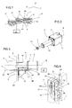
- Figure 1 is a schematic perspective view, partly in blocks, of a throughfeed moulder in accordance with the present invention;
- Figure 2 is a schematic front perspective view, with some parts cut away for greater clarity, of a tool holder chuck unit in accordance with the present invention;
- Figure 3 is a suitably sectioned schematic plan view, with some parts cut away for greater clarity, of a first embodiment of a tool holder chuck unit in accordance with the present invention;
- Figure 4 is a suitably sectioned schematic side view, with some parts cut away for greater clarity, of a second embodiment of a tool holder chuck unit in accordance with the present invention;
- Figure 5 is a schematic side view, partly in cross-section and with some parts cut away for greater clarity, of a tool holder chuck unit in accordance with the present invention;
- Figure 6 is a schematic perspective view, of a supporting element which is part of the tool holder chuck units of the machine in accordance with the present invention.
- With reference to the accompanying drawings and in particular with reference to Figure 1, the
numeral 1 denotes a throughfeed moulder for machiningworkpieces 2 made of wood or the like in accordance with the present invention. - The throughfeed
moulder 1 is described in detail below as regards the technical features which are the subject matter of the present invention, whilst the description of additional, substantially known technical features is limited, simply to allow an understanding of the text. - The throughfeed
moulder 1 comprises a unit which feedsworkpieces 2 along a feed path P in a substantially horizontal direction X. Said feed unit is schematically illustrated with ablock 3. - The throughfeed
moulder 1 comprises, substantially at the feed path P, a plurality of tool units or toolholder chuck units 4 for moulding theworkpieces 2. - In particular, the throughfeed
moulder 1 comprises four tools, known to experts in the field as right-hand vertical 4a, left-hand vertical 4b, upper horizontal 4c and lower horizontal 4d, fitted on respective tool holder spindles and driven by respective motors so that each forms atool unit 4. Advantageously, in alternative embodiments not illustrated, thethroughfeed moulder 1 comprises a greater number of tool holder chuck units depending on the machining required on theworkpieces 2. - The machine also preferably comprises a
fifth tool unit 21, known to experts in the field as the universal unit. - As illustrated in Figures 2 to 5, the
units 4 each comprise a drive unit, preferably anelectric motor 5, and atool 6 associated with themotor 5 by means of atool holder spindle 7. - In particular, each
tool unit 4 comprises releasable clamping means 23 for associating thetool 6 with thetool holder spindle 7. - In particular with reference to the embodiment illustrated in Figure 4, said releasable clamping means 23 consist of a
chuck 8. - The
tool units 4 can move, relative to the path P, in a direction Z substantially perpendicular to the direction of feed X, so that the height of thetools 6 can be adjusted. - The
tool units 4 can also move relative to the path P in a direction Y substantially perpendicular to the directions X and Z, so that therespective tool 6 can be adjusted towards and away from the path P. Said adjustments oftool 6 height and position towards and away from the path P enable thethroughfeed moulder 1 to operate with a plurality ofworkpieces 2 having different dimensions. - For this purpose, the throughfeed
moulder 1 comprises means 9 for supporting thetool units 4, described in more detail below, which allow theunits 4 to be supported and adjustment of the position of thetools 6 relative to the feed path P according to the axes Z and Y. - As illustrated in particular in Figures 2, 3, 4 and 5, each
tool unit 4 comprises aguide tube 10 for thetool holder spindle 7. - In particular, each
tube 10 is preferably cylindrical. - In particular, the
tool holder spindle 7 can move, about an axis of rotation R, in thetube 10 where thetube 10 and thespindle 7 are coaxial. - The
tube 10 is rigidly constrained to themotor 5 and is also preferably rigidly constrained to theelectric motor 5casing 11. - The throughfeed
moulder 1 comprises sliding means 12 operating between thetube 10 and thespindle 7 to reduce the friction between them. - These means 12 preferably comprise a plurality of bearings inserted between the
tube 10 and thespindle 7 and coaxial with them. - In practice the
tube 10 acts as a guide for thespindle 7 using the bearings. - In the preferred embodiment illustrated, the
means 12 comprise a first bearing 13, preferably of the double row type, positioned close to thetool 6. - The
means 12 also comprise a second bearing 14 positioned close to theelectric motor 5. - It should be noticed that the axial distance "L" between the first and
second bearings spindle 7 at thebearings tool holder spindle 7. - As illustrated in Figure 3, the
tool holder spindle 7 is associated with theelectric motor 5rotor 15 by means of acoupling 16 which is preferably flexible. - As illustrated in Figure 4, the
tool holder spindle 7 is made in a single body with themotor 5rotor 15. - The supporting
means 9 are associated with therespective tool unit 4 by thetube 10. - As shown in Figures 5 and 6 by way of example, the supporting
means 9 comprise a supportingelement 17 having atubular portion 18 in which thetube 10 is inserted. - The
tube 10 can also be clamped to theportion 18 and supported by it. - In practice the
tube 10 can be slidably inserted in theportion 18 and can move relative to said portion in the direction Y. - In this way the
tool 6 can move towards and away from theworkpiece 2 being machined. - It should be noticed that the throughfeed
moulder 1 comprises means, not illustrated, for clamping thetool unit 4 relative to the supportingelement 17 in the generic machining configuration required. - The
tool unit 4 is therefore supported by the supportingelement 17 by means of thetube 10 since, as indicated, thetube 10 is rigidly connected to theelectric motor 5casing 11. - The supporting
means 9 comprise a first and asecond guide element 17. - Said
guides respective tool unit 4, since they engage, in the known way, in respective sliders 19', 20' illustrated with a dashed line. - The supporting
means 9 comprise aguide rod 22 used to move thetool unit 4 relative to the supportingelement 17. - The
rod 22 extends substantially parallel with the direction Y and thetool unit 4 can move relative to it by means of the supportingelement 17. - In particular, the
rod 22 has a threadedportion 24 on which asliding element 25 rigidly connected to themotor 5 engages. - The
rod 22 is free to rotate about its axis substantially parallel with the axis Y, since it is suitably inserted in a pair ofcoaxial holes 26 made in the supportingelement 17. - There are
rod 22 drive means, schematically illustrated with ablock 27, for driving the rotation of therod 22, theelement 25 consequently moving thetool unit 4. - It should be noticed that the
throughfeed moulder 1 comprises means 28 for cooling themotor 5, preferably associated with thebase 29 of themotor casing 11. - As illustrated in Figure 3, the cooling means 28 comprise a
fan 30 applied substantially at theelectric motor 5. - Figure 4 shows how the cooling means 28 comprise an
intake pipe 31 opposite the rear part of theelectric motor 5 and in communication with intake means schematically illustrated with a block 32. - The
throughfeed moulder 1 described brings important advantages. - The tool holder spindle is supported and guided by the tube and therefore can be made in the optimum size for achieving the required rigidity with compact dimensions.
- Tool unit cooling is optimised and, in particular, since the chuck is distanced from the motor, it is not subject to thermal expansion which hinders tool change-overs.
- Because all tool support and position adjustments are associated with the tube, the motors are free and accessible, significantly simplifying maintenance operations.
- The invention described has evident industrial applications and can be modified and adapted in several ways without thereby departing from the scope of the inventive concept. Moreover, all details of the invention may be substituted by technically equivalent elements.
Claims (16)
- A throughfeed moulder for machining workpieces (2) made of wood or the like, comprising: a unit (3) for feeding workpieces (2) along a feed path (P); a plurality of tool units (4) positioned at the feed path (P) for moulding the workpieces (2), the tool units (4) each comprising a drive unit (5), in particular an electric motor (5), and a tool (6) associated with the drive unit (5) by a tool holder spindle (7), the machine comprising adjustable supporting means (9) for each tool unit (4), the machine being characterised in that at least one of the tool units (4) comprises a tube (10) for guiding and supporting the tool holder spindle (7), said tool holder spindle (7) being rotatable in the tube (10) and substantially coaxial with it, the tube (10) being rigidly constrained to the motor (5).
- The machine according to claim 1, characterised in that each tool unit (4) comprises the tube (10) for guiding and supporting the tool holder spindle (7).
- The machine according to claim 1 or 2, characterised in that the adjustable supporting means (9) are associated with the respective tool unit (4) by means of the tube (10).
- The machine according to any of the claims from 1 to 3, characterised in that it comprises sliding means (12) operating between the tube (10) and the spindle (7) to reduce the friction when they rotate relative to one another.
- The machine according to claim 4, characterised in that the sliding means (12) comprise at least one first bearing (13) positioned close to the tool (6) and at least one second bearing (14) positioned close to the electric motor (5).
- The machine according to claim 5, characterised in that the axial distance (L) between the first and second bearings (13, 14) and the diameter (d) of the spindle at the first and second bearings (13, 14) are defined according to the rigidity of the tool holder spindle (7) required.
- The machine according to any of the claims from 1 to 6, characterised in that the tool holder spindle (7) is associated with the electric motor (5) rotor (15) by means of a coupling (16) which is preferably flexible.
- The machine according to claim 7, characterised in that the tool holder spindle (7) is coaxial with the rotor (15).
- The machine according to any of the claims from 1 to 6, characterised in that the tool holder spindle (7) is made in a single body with the electric motor (5) rotor (15).
- The machine according to any of the claims from 1 to 9, characterised in that the tube (10) is rigidly constrained to the electric motor (5) casing (11).
- The machine according to any of the claims from 1 to 10, characterised in that the supporting means (9) comprise a supporting element (17) associated with the tube (10).
- The machine according to claim 11, characterised in that the supporting element (17) has a tubular portion (18) in which the tube (10) is inserted.
- The machine according to claim 11 or 12, characterised in that the supporting means (9) comprise at least one guide (19, 20), preferably a prism guide, associated with the supporting element (17) for adjusting the height of the tool unit (4) relative to the feed path (P).
- The machine according to any of the claims from 11 to 13, characterised in that the supporting means (9) comprise at least one guide rod (22) for the supporting element (17), the tool unit (4) being able to move relative to the supporting element (17) by means of the guide rod (22).
- The machine according to any of the claims from 1 to 14, characterised in that it comprises means (28) for cooling the drive unit (5).
- The machine according to any of the claims from 1 to 15, characterised in that the motor (5), the spindle (7) and the tube (10) are coaxial with one another.
Applications Claiming Priority (1)
| Application Number | Priority Date | Filing Date | Title |
|---|---|---|---|
| IT000053A ITBO20060053A1 (en) | 2006-01-31 | 2006-01-31 | MOLDING MACHINE |
Publications (2)
| Publication Number | Publication Date |
|---|---|
| EP1813399A1 true EP1813399A1 (en) | 2007-08-01 |
| EP1813399B1 EP1813399B1 (en) | 2009-08-12 |
Family
ID=37944409
Family Applications (1)
| Application Number | Title | Priority Date | Filing Date |
|---|---|---|---|
| EP07101396A Not-in-force EP1813399B1 (en) | 2006-01-31 | 2007-01-30 | Throughfeed moulder |
Country Status (4)
| Country | Link |
|---|---|
| EP (1) | EP1813399B1 (en) |
| AT (1) | ATE439221T1 (en) |
| DE (1) | DE602007001902D1 (en) |
| IT (1) | ITBO20060053A1 (en) |
Citations (2)
| Publication number | Priority date | Publication date | Assignee | Title |
|---|---|---|---|---|
| US20030205293A1 (en) * | 2002-05-02 | 2003-11-06 | Sylvain Gilbert | Automated planer machine |
| EP1479491A1 (en) * | 2003-05-20 | 2004-11-24 | Otto Martin Maschinenbau GmbH & Co. | Planer |
-
2006
- 2006-01-31 IT IT000053A patent/ITBO20060053A1/en unknown
-
2007
- 2007-01-30 DE DE602007001902T patent/DE602007001902D1/en not_active Expired - Fee Related
- 2007-01-30 AT AT07101396T patent/ATE439221T1/en not_active IP Right Cessation
- 2007-01-30 EP EP07101396A patent/EP1813399B1/en not_active Not-in-force
Patent Citations (2)
| Publication number | Priority date | Publication date | Assignee | Title |
|---|---|---|---|---|
| US20030205293A1 (en) * | 2002-05-02 | 2003-11-06 | Sylvain Gilbert | Automated planer machine |
| EP1479491A1 (en) * | 2003-05-20 | 2004-11-24 | Otto Martin Maschinenbau GmbH & Co. | Planer |
Also Published As
| Publication number | Publication date |
|---|---|
| ITBO20060053A1 (en) | 2007-08-01 |
| DE602007001902D1 (en) | 2009-09-24 |
| EP1813399B1 (en) | 2009-08-12 |
| ATE439221T1 (en) | 2009-08-15 |
Similar Documents
| Publication | Publication Date | Title |
|---|---|---|
| US8404997B2 (en) | Machine arrangement for machining bar-like workpieces having a device for workpiece support | |
| KR100983967B1 (en) | Precision roll lathe | |
| US8020267B2 (en) | Precision roll turning lathe | |
| CN102198529B (en) | Deep hole drilling machine | |
| CN106514260B (en) | Multi-shaft high-speed numerically controlled lathe | |
| CN107520619A (en) | A kind of inclined end face milling drill centres machine tool | |
| US20140102269A1 (en) | Precision CNC Facing Lathe | |
| CN102729708B (en) | Numerical control three-dimensional engraving machine | |
| KR101713439B1 (en) | Machining center for multi-spindle | |
| CN115741263B (en) | A silicon carbide multifunctional high-speed rolling grinder | |
| US5238339A (en) | Machine tool for working flat workpieces | |
| CN113334163A (en) | High-precision vertical and horizontal dual-purpose composite grinding machine adopting mineral castings | |
| KR20160076259A (en) | Machine tool | |
| EP1813399B1 (en) | Throughfeed moulder | |
| US7179029B2 (en) | Machine for machining workpieces, especially crankshafts and camshafts, with at least one internal cutter milling tool | |
| CN109719329A (en) | A kind of slotter for elongated shaft milling through slot | |
| CN101367254A (en) | Light-duty universal bidirectional stone cutter | |
| KR100983950B1 (en) | Precision roll turning lathe | |
| CN105328492A (en) | Main transmission system of horizontal numerical control boring and milling machine | |
| CN220761937U (en) | High-precision cylindrical grinding machine device | |
| CN201596805U (en) | Curved surface cutting device | |
| CN207272682U (en) | A kind of inclined end face milling drill centres machine tool | |
| CN214350345U (en) | A support device for laser cutting of circular section workpiece and laser cutting equipment | |
| CN204893102U (en) | A lathe for making gear | |
| CN111152027B (en) | Steel bar drilling, tapping and cutting machine and operation process |
Legal Events
| Date | Code | Title | Description |
|---|---|---|---|
| PUAI | Public reference made under article 153(3) epc to a published international application that has entered the european phase |
Free format text: ORIGINAL CODE: 0009012 |
|
| AK | Designated contracting states |
Kind code of ref document: A1 Designated state(s): AT BE BG CH CY CZ DE DK EE ES FI FR GB GR HU IE IS IT LI LT LU LV MC NL PL PT RO SE SI SK TR |
|
| AX | Request for extension of the european patent |
Extension state: AL BA HR MK YU |
|
| 17P | Request for examination filed |
Effective date: 20080123 |
|
| AKX | Designation fees paid |
Designated state(s): AT BE BG CH CY CZ DE DK EE ES FI FR GB GR HU IE IS IT LI LT LU LV MC NL PL PT RO SE SI SK TR |
|
| 17Q | First examination report despatched |
Effective date: 20080902 |
|
| GRAP | Despatch of communication of intention to grant a patent |
Free format text: ORIGINAL CODE: EPIDOSNIGR1 |
|
| GRAS | Grant fee paid |
Free format text: ORIGINAL CODE: EPIDOSNIGR3 |
|
| GRAA | (expected) grant |
Free format text: ORIGINAL CODE: 0009210 |
|
| AK | Designated contracting states |
Kind code of ref document: B1 Designated state(s): AT BE BG CH CY CZ DE DK EE ES FI FR GB GR HU IE IS IT LI LT LU LV MC NL PL PT RO SE SI SK TR |
|
| REG | Reference to a national code |
Ref country code: GB Ref legal event code: FG4D |
|
| REG | Reference to a national code |
Ref country code: CH Ref legal event code: EP |
|
| REG | Reference to a national code |
Ref country code: IE Ref legal event code: FG4D |
|
| REF | Corresponds to: |
Ref document number: 602007001902 Country of ref document: DE Date of ref document: 20090924 Kind code of ref document: P |
|
| LTIE | Lt: invalidation of european patent or patent extension |
Effective date: 20090812 |
|
| PG25 | Lapsed in a contracting state [announced via postgrant information from national office to epo] |
Ref country code: SE Free format text: LAPSE BECAUSE OF FAILURE TO SUBMIT A TRANSLATION OF THE DESCRIPTION OR TO PAY THE FEE WITHIN THE PRESCRIBED TIME-LIMIT Effective date: 20090812 Ref country code: LT Free format text: LAPSE BECAUSE OF FAILURE TO SUBMIT A TRANSLATION OF THE DESCRIPTION OR TO PAY THE FEE WITHIN THE PRESCRIBED TIME-LIMIT Effective date: 20090812 Ref country code: IS Free format text: LAPSE BECAUSE OF FAILURE TO SUBMIT A TRANSLATION OF THE DESCRIPTION OR TO PAY THE FEE WITHIN THE PRESCRIBED TIME-LIMIT Effective date: 20091212 Ref country code: ES Free format text: LAPSE BECAUSE OF FAILURE TO SUBMIT A TRANSLATION OF THE DESCRIPTION OR TO PAY THE FEE WITHIN THE PRESCRIBED TIME-LIMIT Effective date: 20091123 Ref country code: FI Free format text: LAPSE BECAUSE OF FAILURE TO SUBMIT A TRANSLATION OF THE DESCRIPTION OR TO PAY THE FEE WITHIN THE PRESCRIBED TIME-LIMIT Effective date: 20090812 Ref country code: AT Free format text: LAPSE BECAUSE OF FAILURE TO SUBMIT A TRANSLATION OF THE DESCRIPTION OR TO PAY THE FEE WITHIN THE PRESCRIBED TIME-LIMIT Effective date: 20090812 |
|
| NLV1 | Nl: lapsed or annulled due to failure to fulfill the requirements of art. 29p and 29m of the patents act | ||
| PG25 | Lapsed in a contracting state [announced via postgrant information from national office to epo] |
Ref country code: NL Free format text: LAPSE BECAUSE OF FAILURE TO SUBMIT A TRANSLATION OF THE DESCRIPTION OR TO PAY THE FEE WITHIN THE PRESCRIBED TIME-LIMIT Effective date: 20090812 Ref country code: SI Free format text: LAPSE BECAUSE OF FAILURE TO SUBMIT A TRANSLATION OF THE DESCRIPTION OR TO PAY THE FEE WITHIN THE PRESCRIBED TIME-LIMIT Effective date: 20090812 Ref country code: LV Free format text: LAPSE BECAUSE OF FAILURE TO SUBMIT A TRANSLATION OF THE DESCRIPTION OR TO PAY THE FEE WITHIN THE PRESCRIBED TIME-LIMIT Effective date: 20090812 Ref country code: PL Free format text: LAPSE BECAUSE OF FAILURE TO SUBMIT A TRANSLATION OF THE DESCRIPTION OR TO PAY THE FEE WITHIN THE PRESCRIBED TIME-LIMIT Effective date: 20090812 |
|
| PG25 | Lapsed in a contracting state [announced via postgrant information from national office to epo] |
Ref country code: BG Free format text: LAPSE BECAUSE OF FAILURE TO SUBMIT A TRANSLATION OF THE DESCRIPTION OR TO PAY THE FEE WITHIN THE PRESCRIBED TIME-LIMIT Effective date: 20091112 Ref country code: PT Free format text: LAPSE BECAUSE OF FAILURE TO SUBMIT A TRANSLATION OF THE DESCRIPTION OR TO PAY THE FEE WITHIN THE PRESCRIBED TIME-LIMIT Effective date: 20091212 |
|
| PG25 | Lapsed in a contracting state [announced via postgrant information from national office to epo] |
Ref country code: DK Free format text: LAPSE BECAUSE OF FAILURE TO SUBMIT A TRANSLATION OF THE DESCRIPTION OR TO PAY THE FEE WITHIN THE PRESCRIBED TIME-LIMIT Effective date: 20090812 Ref country code: RO Free format text: LAPSE BECAUSE OF FAILURE TO SUBMIT A TRANSLATION OF THE DESCRIPTION OR TO PAY THE FEE WITHIN THE PRESCRIBED TIME-LIMIT Effective date: 20090812 Ref country code: EE Free format text: LAPSE BECAUSE OF FAILURE TO SUBMIT A TRANSLATION OF THE DESCRIPTION OR TO PAY THE FEE WITHIN THE PRESCRIBED TIME-LIMIT Effective date: 20090812 Ref country code: CZ Free format text: LAPSE BECAUSE OF FAILURE TO SUBMIT A TRANSLATION OF THE DESCRIPTION OR TO PAY THE FEE WITHIN THE PRESCRIBED TIME-LIMIT Effective date: 20090812 |
|
| PG25 | Lapsed in a contracting state [announced via postgrant information from national office to epo] |
Ref country code: SK Free format text: LAPSE BECAUSE OF FAILURE TO SUBMIT A TRANSLATION OF THE DESCRIPTION OR TO PAY THE FEE WITHIN THE PRESCRIBED TIME-LIMIT Effective date: 20090812 |
|
| PLBE | No opposition filed within time limit |
Free format text: ORIGINAL CODE: 0009261 |
|
| STAA | Information on the status of an ep patent application or granted ep patent |
Free format text: STATUS: NO OPPOSITION FILED WITHIN TIME LIMIT |
|
| PG25 | Lapsed in a contracting state [announced via postgrant information from national office to epo] |
Ref country code: BE Free format text: LAPSE BECAUSE OF FAILURE TO SUBMIT A TRANSLATION OF THE DESCRIPTION OR TO PAY THE FEE WITHIN THE PRESCRIBED TIME-LIMIT Effective date: 20090812 |
|
| 26N | No opposition filed |
Effective date: 20100517 |
|
| PG25 | Lapsed in a contracting state [announced via postgrant information from national office to epo] |
Ref country code: MC Free format text: LAPSE BECAUSE OF NON-PAYMENT OF DUE FEES Effective date: 20100131 |
|
| REG | Reference to a national code |
Ref country code: FR Ref legal event code: ST Effective date: 20100930 |
|
| PG25 | Lapsed in a contracting state [announced via postgrant information from national office to epo] |
Ref country code: FR Free format text: LAPSE BECAUSE OF NON-PAYMENT OF DUE FEES Effective date: 20100201 Ref country code: GR Free format text: LAPSE BECAUSE OF FAILURE TO SUBMIT A TRANSLATION OF THE DESCRIPTION OR TO PAY THE FEE WITHIN THE PRESCRIBED TIME-LIMIT Effective date: 20091113 |
|
| PG25 | Lapsed in a contracting state [announced via postgrant information from national office to epo] |
Ref country code: DE Free format text: LAPSE BECAUSE OF NON-PAYMENT OF DUE FEES Effective date: 20100803 |
|
| PG25 | Lapsed in a contracting state [announced via postgrant information from national office to epo] |
Ref country code: IE Free format text: LAPSE BECAUSE OF NON-PAYMENT OF DUE FEES Effective date: 20100130 |
|
| PG25 | Lapsed in a contracting state [announced via postgrant information from national office to epo] |
Ref country code: IT Free format text: LAPSE BECAUSE OF FAILURE TO SUBMIT A TRANSLATION OF THE DESCRIPTION OR TO PAY THE FEE WITHIN THE PRESCRIBED TIME-LIMIT Effective date: 20090812 |
|
| REG | Reference to a national code |
Ref country code: CH Ref legal event code: PL |
|
| GBPC | Gb: european patent ceased through non-payment of renewal fee |
Effective date: 20110130 |
|
| PG25 | Lapsed in a contracting state [announced via postgrant information from national office to epo] |
Ref country code: LI Free format text: LAPSE BECAUSE OF NON-PAYMENT OF DUE FEES Effective date: 20110131 Ref country code: CH Free format text: LAPSE BECAUSE OF NON-PAYMENT OF DUE FEES Effective date: 20110131 |
|
| PG25 | Lapsed in a contracting state [announced via postgrant information from national office to epo] |
Ref country code: GB Free format text: LAPSE BECAUSE OF NON-PAYMENT OF DUE FEES Effective date: 20110130 |
|
| PG25 | Lapsed in a contracting state [announced via postgrant information from national office to epo] |
Ref country code: CY Free format text: LAPSE BECAUSE OF FAILURE TO SUBMIT A TRANSLATION OF THE DESCRIPTION OR TO PAY THE FEE WITHIN THE PRESCRIBED TIME-LIMIT Effective date: 20090812 |
|
| PG25 | Lapsed in a contracting state [announced via postgrant information from national office to epo] |
Ref country code: LU Free format text: LAPSE BECAUSE OF NON-PAYMENT OF DUE FEES Effective date: 20100130 Ref country code: HU Free format text: LAPSE BECAUSE OF FAILURE TO SUBMIT A TRANSLATION OF THE DESCRIPTION OR TO PAY THE FEE WITHIN THE PRESCRIBED TIME-LIMIT Effective date: 20100213 |
|
| PG25 | Lapsed in a contracting state [announced via postgrant information from national office to epo] |
Ref country code: TR Free format text: LAPSE BECAUSE OF FAILURE TO SUBMIT A TRANSLATION OF THE DESCRIPTION OR TO PAY THE FEE WITHIN THE PRESCRIBED TIME-LIMIT Effective date: 20090812 |