EP1813369B1 - Werkzeughalter und Werkzeugmaschine mit Arbeitsspindel und Werkzeughalter - Google Patents
Werkzeughalter und Werkzeugmaschine mit Arbeitsspindel und Werkzeughalter Download PDFInfo
- Publication number
- EP1813369B1 EP1813369B1 EP06024564A EP06024564A EP1813369B1 EP 1813369 B1 EP1813369 B1 EP 1813369B1 EP 06024564 A EP06024564 A EP 06024564A EP 06024564 A EP06024564 A EP 06024564A EP 1813369 B1 EP1813369 B1 EP 1813369B1
- Authority
- EP
- European Patent Office
- Prior art keywords
- tool
- fluid line
- fluid
- tool holder
- adapter sleeve
- Prior art date
- Legal status (The legal status is an assumption and is not a legal conclusion. Google has not performed a legal analysis and makes no representation as to the accuracy of the status listed.)
- Active
Links
Images
Classifications
-
- B—PERFORMING OPERATIONS; TRANSPORTING
- B23—MACHINE TOOLS; METAL-WORKING NOT OTHERWISE PROVIDED FOR
- B23B—TURNING; BORING
- B23B31/00—Chucks; Expansion mandrels; Adaptations thereof for remote control
- B23B31/02—Chucks
- B23B31/24—Chucks characterised by features relating primarily to remote control of the gripping means
- B23B31/26—Chucks characterised by features relating primarily to remote control of the gripping means using mechanical transmission through the working-spindle
- B23B31/261—Chucks characterised by features relating primarily to remote control of the gripping means using mechanical transmission through the working-spindle clamping the end of the toolholder shank
- B23B31/265—Chucks characterised by features relating primarily to remote control of the gripping means using mechanical transmission through the working-spindle clamping the end of the toolholder shank by means of collets
-
- B—PERFORMING OPERATIONS; TRANSPORTING
- B23—MACHINE TOOLS; METAL-WORKING NOT OTHERWISE PROVIDED FOR
- B23B—TURNING; BORING
- B23B2250/00—Compensating adverse effects during turning, boring or drilling
- B23B2250/12—Cooling and lubrication
Definitions
- the invention relates to a tool holder for coupling a tool to a work spindle of a machine tool, with a chuck body, in each of which facing away from one another, end areas a coupling structure for an automated coupling to the work spindle and a tool holder for fixing the tool are assigned, wherein between the end A longitudinally extending along a central axis fluid line is provided, which is designed for forwarding at least one fluid from the coupling structure in the direction of the tool and which has a downstream in the tool holder, arranged along the central axis adjustable, adapter sleeve, for a length adjustment of the fluid line is provided to different positions of the tool in the tool holder and having at least one key surface for the introduction of an adjusting force, and a machine tool with a work spindle and egg a tool holder.
- a tool holder for coupling a tool to a work spindle of a machine tool has a chuck body serving as an adapter between a tool, in particular a cutting tool such as a milling cutter or a drill, and a work spindle of a machine tool is provided and which is designed for automated coupling and decoupling of the tool holder to the work spindle.
- a coupling structure which can preferably be positively locked to the work spindle and which is designed for the transmission of forces from the work spindle to the tool.
- the coupling structure can be designed in particular as a hollow shaft cone, preferably according to DIN 69893.
- a provided on the known chuck body tool holder is designed as a cylindrical bore having a slightly reduced diameter relative to a cylindrical shaft of the male tool, so that an interference fit between the tool holder and the shank of the tool is present.
- the tool is used by means of a preferably thermal clamping process almost force-free in the tool holder and removed from the tool holder. In the same way, other common clamping types can be provided.
- a fluid line is provided between the coupling structure and the tool holder, which is used to forward an aerosol, ie a mixture Compressed air and a lubricant is determined.
- the aerosol passes in the region of the tool holder through an adapter sleeve, which is provided for a length adjustment of the fluid line.
- a length adjustment of the fluid line to the position of the tool in the tool holder is made to avoid unwanted cross-section jumps in a transition region between the fluid line and cooling channels of the tool, to avoid adhesion of lubricant droplets in the fluid line.
- the adapter sleeve can be approximated to the tool after insertion of the tool in the tool holder.
- the aerosol After passing through the adapter sleeve, the aerosol enters one or more provided in the tool cooling channels, which ensure a transmission of the aerosol up to the cutting edges of the tool.
- the adapter sleeve is provided with inwardly directed key surfaces in the manner of a hexagon socket. To avoid cross-sectional jumps in the fluid line, this is designed in the region of the adapter sleeve as a fluid tube, wherein an outer diameter of the fluid tube deviates only slightly from an inscribed circle of the key surfaces, so that the fluid tube conforms to the key surfaces of the adapter sleeve.
- a length adjustment of the fluid line is particularly necessary when the tool is received after re-sharpening the cutting with a changed position in the tool holder.
- the changed position can result from a shortening of the tool during the re-sharpening process, if, for example, a distance between the coupling structure and a leading edge of the tool is to be kept constant.
- a tool holder with the generic features of claim 1 is from the document DE 103 12 743 A1 known.
- the tool holder has an adjusting sleeve designated as an adapter sleeve, which contains an engagement for a setting tool. Since the cross section of the engagement is greater than the cross section of the fluid line, which leads through the adjusting screw, an adjustment of the adapter sleeve is possible only at the upstream end. It is not possible to guide an adjustment tool through the fluid line.
- the fluid tube must be routed outwards over the adapter sleeve at the upstream end.
- the object of the invention is to provide a tool holder and a machine tool, which allow an improved adaptation of the fluid line to different tool positions.
- a tool holder of the type mentioned in which a minimum cross section of the fluid line is at least substantially determined by the at least one key surface of the adapter sleeve, so that an adjustment of the adapter sleeve through the fluid line through when inserted tool is possible.
- a cross section of the fluid line is determined in a cross-sectional plane aligned orthogonally to the central axis of the chuck body and describes a surface area which is available for the flow process of the aerosol perpendicular to a flow direction of the aerosol.
- a narrow cross-section is provided for the fluid line, which ensures a high flow velocity and thus a low precipitation of the aerosol in the fluid line.
- the at least one wrench surface defines a minimum cross-section of the fluid conduit, that is, the area in the cross-sectional plane that intersects the wrench surface is minimal relative to the other surface regions of the fluid conduit. This can be ensured that an adjustment of the adapter sleeve despite an already used tool and without removal of parts of the fluid line, in particular the fluid pipe, is possible.
- the adjusting means adapted to the minimal cross section of the fluid conduit being guided by the end region of the chuck body provided with the coupling structure through the fluid conduit, in particular through the fluid conduit, and a preferably form-fitting, force-transmitting Connection with the at least one key surface of the adapter sleeve is received.
- a telescopic overlap of the adapter sleeve with the fluid line is designed such that an adjustment for the adapter sleeve corresponds to at least one diameter of the tool holder, preferably at least 1.2 times the diameter of the tool holder. Particularly advantageous is the adjustment 10 mm.
- a telescopic overlap between the adapter sleeve and the fluid line may be provided by a plug connection between a hollow cylindrical portion of the adapter sleeve and the fluid tube.
- the geometries of the adapter sleeve and the fluid tube are matched to one another such that a fluid-tight in normal operation, along a central axis of the chuck body slide-movable connector is realized.
- a maximum insertion depth between the adapter sleeve and the fluid tube is selected so that an adjustment path, ie a sliding movement region between adapter sleeve and fluid tube, preferably corresponds at least to the diameter of the tool holder.
- a mean cross section of the fluid line is at most 20 times greater, preferably at most 10 times greater, more preferably at most 5 times greater than a central cooling channel cross section provided in the tool.
- the average cross section can be determined by averaging all cross sections occurring in the fluid line or in the cooling channel, taking into account the respective length of the fluid line or the cooling channel, which have the same cross section.
- the tool holder has a coupling sleeve for connecting the fluid line of the tool holder with a fluid channel of the work spindle and a fluid tube for connecting the coupling sleeve with the adapter sleeve, wherein the fluid tube is connected to the coupling sleeve by means of a flexible connecting means.
- the coupling sleeve serves to receive in a fluid channel of the work spindle. In order to ensure trouble-free insertion of the coupling sleeve in this fluid channel even with rapid tool changes, the coupling sleeve must be deflected to a limited extent, at least approximately 1.5 °.
- the connecting means is arranged between an outer diameter of the fluid tube and an inner diameter of the coupling sleeve, wherein the connecting means is preferably designed as an elastic intermediate element, in particular as an O-ring.
- This design is particularly inexpensive and easy to implement.
- the fluid tube is preferably provided for this purpose with means for positively receiving the O-ring or other intermediate element. In the simplest case, this is a circumferential groove.
- the intermediate element can also be applied directly to the fluid tube or an inner surface of the coupling sleeve, in particular vulcanized.
- a machine tool with a work spindle and a tool holder according to one of claims 1 to 3 is provided.
- the work spindle has a tubular shaft with an end-side coupling device for a transmission of forces and movements to the tool holder, wherein the coupling device has a truncated-cone-shaped receiving opening, a clamping jaw which can be locked in a form-locking manner with the tool holder and has a clamping bush provided for driving the collet, which has at least two separate, in particular concentrically arranged, fluid channels for conveying fluids in the direction of the tool holder.
- the two fluid channels are provided for separate delivery of two different fluids, in particular a lubricant and compressed air, and may be provided concentrically in the manner of a substantially cylindrical bore for the compressed air and a concentrically arranged in the bore tubular lance for the lubricant.
- the lance for the lubricant may be provided in the region of the coupling device of the work spindle with a nozzle opening, so that a mixing of the fluids in the region of the coupling device is provided.
- the mixing of the fluids and the formation of the oil / air mixture take place directly in the tool holder, so that the oil / air mixture only has to travel a short distance to the cooling channels in the tool.
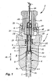
- the in Fig. 1 shown tool holder 1 is provided for a coupling of a dashed line indicated, cylindrically shaped tool 2 to a partially illustrated work spindle 3 of a machine tool, not shown.
- the tool holder 1 has a chuck body 4, which is designed substantially rotationally symmetrical to a central axis 21 and which is provided with a through bore which partially different functional areas, for example for receiving a tool 2 or for receiving a coupling sleeve 30 has.
- a coupling structure 5 designed as a hollow shaft cone for automatic coupling to the work spindle 3 is provided on the chuck body 4.
- the work spindle 3 has for this purpose a clamping bushing 18 and provided with a radially outwardly facing latch hook 33 collet 17 which can be pressed by a translational relative movement of the clamping sleeve 18 against a locking groove 34 of the coupling structure 5 and thus positively locked.
- the bore in the chuck body 4 is designed as a tool holder 6 for fixing the tool 2 and provided for a thermal clamping or unclamping operation. Between the end regions, the bore is provided with a fluid line 7 extending along the central axis 21.
- the fluid line 7 is designed for a forwarding of at least one fluid from the coupling structure 5 in the direction of the tool 2.
- the fluid line 7 is realized in the region of the coupling structure 5 as a coupling sleeve 30 with a circular cross-section and is used for sealing coupling to the clamping bush 18.
- a coupling sleeve 30 In the clamping bush 18 is a compressed air bore 19 and a concentrically arranged in the compressed air bore 19, tubular lance 20 for transporting a liquid lubricant provided.
- the coupling sleeve 30 can be inserted into the compressed air bore 19 and thus forms a continuation of the compressed air bore 19 in the tool holder 1.
- two O-rings 35 between the coupling sleeve 30 and the chuck body 4 of the tool holder 1 is provided.
- the lance 20 projects with coupled tool holder 1 into a fluid line associated fluid bushing 28 which has a relation to the coupling sleeve 30 reduced cross-section and as a mixing chamber 29 for in the compressed air bore 19 flowing compressed air and the lubricant transported in the lance 20 is used.
- the mixing chamber 29 the lubricant exiting from a metering opening 31 of the lance 20, in the present case oil, is atomized by the compressed air and thereby forms an oil / air mixture which is conveyed through the fluid line 7 in the direction of the tool 2.
- Adjoining the fluid bushing 28 is a fluid tube 27, which has a circular cross-section which is constant over the entire length of the fluid tube 27.
- an adapter sleeve 8 which is adjustable along the central axis, is provided in the region of the tool holder 6 adjacent to the fluid tube 27, which permits a length adaptation of the fluid line 7 to different positions of the tool 2.
- the adapter sleeve 8 has a sleeve portion 22 which is designed in the manner of a hollow cylinder and which is provided on an outer surface with an external thread 25 which engages in an internal thread 26 of the chuck body 4 and a translational adjustment of the adapter sleeve 8 along the central axis 21st made possible by means of a rotational movement.
- An inner diameter of the sleeve portion 22 is adapted to the fluid pipe 27, so that a telescopic, preferably sealing plug connection between the sleeve portion 22 and the fluid pipe 27 is realized.
- the fluid tube 27 protrudes into the adapter sleeve 8 and ends in the in Fig. 1
- the key surfaces 9 are arranged in the manner of a hexagon socket, wherein a radius around the wrench flats 9 approximately corresponds to the circular cross-section of the fluid pipe 27.
- An inscribed circle that is to say a circle tangent to the wrench flats 9, is at least slightly smaller than the circular cross section of the fluid tube 27.
- an adjusting means (not shown in detail), in particular an Allen wrench, can pass from the end region of the chuck body 4 provided with the coupling structure 5 through the fluid line 7 through, in particular by the fluid pipe 27, are guided and can form a positive, force-transmitting connection with the key surfaces 9, to effect an adjustment of the adapter sleeve 8.
- the limited by the wrench flats 9, also referred to as hexagonal portion 24 minimal cross section of the fluid line 7 is in the illustrated embodiment in a conical section 23, which ensures a transfer of the fluid line 7 in the tool holder 6.
- the tool 2 has two parallel cooling channels 32, which are realized as through holes.
- the minimum cross section of the fluid line in the region of the hexagonal section 24 in the exemplary embodiment shown is approximately eight times the cross section of the two cooling channels 32.
- An adjustment 12 of the adapter sleeve 8 is for the present tool holder at a diameter of the tool holder 6 of 8mm at least 10mm, so that a typical shortening of the tool 2 by regrinding the cutting and at a constant distance between the coupling structure 5 and the tip of the tool 2 by adjusting the adapter sleeve 8 can be compensated.
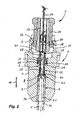
- Fig. 2 shows a second embodiment, compared to the first embodiment of Fig. 1 with respect to the region of the coupling sleeve 30, the fluid bushing 28 and the fluid pipe 27 is modified.
- the reference numerals used in this second embodiment correspond to the reference numerals of each comparable components of the first embodiment of the Fig. 1 ,
- the coupling sleeve 30 and the fluid tube 27 is not a rigid unit. Instead, an O-ring 36 is provided between the inner fluid tube 27 and the outer coupling sleeve 30, which forms a joint as it allows, which allows a relative pivoting movement between the fluid tube 27 and the coupling sleeve 30.
- deflection of the coupling sleeve 30 by a maximum of 1.5 ° to compensate for a positional inaccuracy is not hindered by the fluid pipe 27 due to this joint, even if this is not formed elastically deformable. It can accordingly be rigid, preferably metallic.
- the inner fluid tube 27 and the outer chuck body 4 thus remain in a fixed position to each other, while the coupling sleeve 30, which is movably mounted on the fluid pipe 27 and the chuck body 4 by the O-rings 35, 36, to compensate for positional inaccuracies.
Landscapes
- Engineering & Computer Science (AREA)
- Mechanical Engineering (AREA)
- Jigs For Machine Tools (AREA)
- Auxiliary Devices For Machine Tools (AREA)
- Gripping On Spindles (AREA)
Description
- Die Erfindung betrifft einen Werkzeughalter zur Ankopplung eines Werkzeugs an eine Arbeitsspindel einer Werkzeugmaschine, mit einem Futterkörper, dem in jeweils voneinander abgewandten, endseitigen Bereichen eine Kupplungsstruktur für eine automatisierte Ankopplung an die Arbeitsspindel und eine Werkzeugaufnahme zur Festlegung des Werkzeugs zugeordnet sind, wobei zwischen den endseitigen Bereichen eine längs einer Mittelachse erstreckte Fluidleitung vorgesehen ist, die für eine Weiterleitung zumindest eines Fluids von der Kupplungsstruktur in Richtung des Werkzeugs gestaltet ist und die eine stromabwärts im Bereich der Werkzeugaufnahme angeordnete, längs der Mittelachse verstellbare, Adapterhülse aufweist, die für eine Längenanpassung der Fluidleitung an unterschiedliche Positionen des Werkzeugs in der Werkzeugaufnahme vorgesehen ist und die zumindest eine Schlüsselfläche zur Einleitung einer Verstellkraft aufweist, sowie eine Werkzeugmaschine mit einer Arbeitsspindel und einem Werkzeughalter.
- Ein Werkzeughalter zur Ankopplung eines Werkzeugs an eine Arbeitsspindel einer Werkzeugmaschine ist bekannt. Der Werkzeughalter weist einen Futterkörper auf, der als Adapter zwischen einem Werkzeug, insbesondere einem Schneidwerkzeug wie einem Fräser oder einem Bohrer, und einer Arbeitsspindel einer Werkzeugmaschine vorgesehen ist und der für eine automatisierte Ankopplung und Abkopplung des Werkzeughalters an die Arbeitsspindel gestaltet ist. Für die automatisierte An- und Abkopplung ist der Futterkörper mit einer Kupplungsstruktur versehen, die vorzugsweise formschlüssig an der Arbeitsspindel verriegelt werden kann und die für die Übertragung von Kräften von der Arbeitsspindel auf das Werkzeug gestaltet ist. Die Kupplungsstruktur kann insbesondere als Hohlschaftkegel, bevorzugt nach DIN 69893, ausgeführt sein.
- Eine am bekannten Futterkörper vorgesehene Werkzeugaufnahme ist als zylindrische Bohrung ausgeführt, die gegenüber einem zylindrischen Schaft des aufzunehmenden Werkzeugs einen geringfügig verringerten Durchmesser aufweist, so dass eine Übermaßpassung zwischen Werkzeugaufnahme und dem Schaft des Werkzeugs vorliegt. Das Werkzeug wird mittels eines vorzugsweise thermischen Spannprozesses nahezu kraftfrei in die Werkzeugaufnahme eingesetzt bzw. aus der Werkzeugaufnahme entnommen. In gleicher Weise können auch andere übliche Spannarten vorgesehen werden.
- Um eine Schmierstoffversorgung, insbesondere in der Art einer Minimalmengenschmierung, des typischerweise mit endseitig angeordneten Schneiden in der Art eines Bohrers oder Fräsers versehenen Werkzeugs zu gewährleisten, ist zwischen der Kupplungsstruktur und der Werkzeugaufnahme eine Fluidleitung vorgesehen, die zur Weiterleitung eines Aerosols, also eines Gemisches aus Druckluft und einem Schmiermittel, bestimmt ist. Das Aerosol tritt im Bereich der Werkzeugaufnahme durch eine Adapterhülse, die für eine Längenanpassung der Fluidleitung vorgesehen ist. Eine Längenanpassung der Fluidleitung an die Position des Werkzeugs in der Werkzeugaufnahme wird zur Vermeidung von unerwünschten Querschnittsprüngen in einem Übergangsbereich zwischen der Fluidleitung und Kühlkanälen des Werkzeugs vorgenommen, um eine Anhaftung von Schmiermitteltröpfchen in der Fluidleitung zu vermeiden. Daher kann die Adapterhülse nach Einbringen des Werkzeugs in die Werkzeugaufnahme an das Werkzeug angenähert werden. Nach Passieren der Adapterhülse tritt das Aerosol in einen oder mehrere im Werkzeug vorgesehene Kühlkanäle ein, die eine Weiterleitung des Aerosols bis zu den Schneiden des Werkzeugs gewährleisten.
- Um eine Verstellung der Adapterhülse längs einer Mittelachse des Futterkörpers zu ermöglichen, ist die Adapterhülse mit nach innen gerichteten Schlüsselflächen in der Art eines Innensechskants versehen. Um Querschnittssprünge in der Fluidleitung zu vermeiden, ist diese im Bereich der Adapterhülse als Fluidrohr ausgeführt, wobei ein Außendurchmesser des Fluidrohrs nur geringfügig von einem Inkreis der Schlüsselflächen abweicht, so dass sich das Fluidrohr an die Schlüsselflächen der Adapterhülse anschmiegt. Um eine Verstellung der Adapterhülse nach Einsetzen des Werkzeugs in die Werkzeugaufnahme vorzunehmen, ist bei dem bekannten Werkzeughalter vorgesehen, das Fluidrohr aus dem Werkzeughalter zu entnehmen, so dass die Schlüsselflächen der Adapterhülse freigelegt werden. Dann kann mittels eines Einstellwerkzeugs, beispielsweise eines Innensechskantschlüssels eine Verstellkraft auf Schlüsselflächen der Adapterhülse ausgeübt werden, um mittels einer Schraubbewegung die gewünschte Verstellung der Adapterhülse in Richtung des Werkzeugs und somit die gewünschte Längenanpassung der Fluidleitung zu bewirken. Anschließend kann das Fluidrohr wieder in den Werkzeughalter eingesetzt werden und das Werkzeug steht für die Ankopplung an die Arbeitsspindel der Werkzeugmaschine bereit.
- Eine Längenanpassung der Fluidleitung ist insbesondere dann notwendig, wenn das Werkzeug nach einem Nachschärfen der Schneiden mit einer veränderten Position in der Werkzeugaufnahme aufgenommen wird. Die veränderte Position kann sich durch eine Verkürzung des Werkzeugs beim Nachschärfvorgang ergeben, wenn beispielsweise ein Abstand zwischen der Kupplungsstruktur und einer Werkzeugvorderkante konstant gehalten werden soll.
- Ein Werkzeughalter mit den gattungsbildenden Merkmalen des Patentanspruchs 1 ist aus dem Dokument
DE 103 12 743 A1 bekannt. Der Werkzeughalter weist eine als Stellschraube bezeichnete Adapterhülse auf, die einen Eingriff für ein Stellwerkzeug enthält. Da der Querschnitt des Eingriffs größer ist als der Querschnitt der Fluidleitung, die durch die Stellschraube führt, ist eine Verstellung der Adapterhülse nur an deren stromaufwärtigen Ende möglich. Es ist nicht möglich, ein Verstellwerkzeug durch die Fluidleitung zu führen. Das Fluidrohr muss am stromaufwärtigen Ende außen über die Adapterhülse geführt werden. - Die Aufgabe der Erfindung besteht darin, einen Werkzeughalter und eine Werkzeugmaschine zu schaffen, die eine verbesserte Anpassung der Fluidleitung an unterschiedliche Werkzeugpositionen ermöglichen.
- Diese Aufgabe wird gemäß einem ersten Aspekt der Erfindung durch einen Werkzeughalter der eingangs genannten Art gelöst, bei dem ein Minimalquerschnitt der Fluidleitung zumindest im Wesentlichen durch die zumindest eine Schlüsselfläche der Adapterhülse bestimmt ist, so dass eine Verstellung der Adapterhülse durch die Fluidleitung hindurch bei eingesetztem Werkzeug möglich ist. Ein Querschnitt der Fluidleitung wird in einer orthogonal zur Mittelachse des Futterkörpers ausgerichteten Querschnittsebene ermittelt und beschreibt einen Flächenbereich, der für den Strömungsvorgang des Aerosols senkrecht zu einer Strömungsrichtung des Aerosols zur Verfügung steht. Um einen unerwünschten Niederschlag des Aerosols im Bereich der Fluidleitung zu vermeiden, ist für die Fluidleitung ein enger Querschnitt vorgesehen, der eine hohe Strömungsgeschwindigkeit und somit einen geringen Niederschlag des Aerosols in der Fluidleitung gewährleistet. Die zumindest eine Schlüsselfläche begrenzt einen Minimalquerschnitt der Fluidleitung, das heißt, dass der Flächenbereich in der Querschnittsebene, die die Schlüsselfläche schneidet, minimal gegenüber den anderen Flächenbereichen der Fluidleitung ist. Damit kann gewährleistet werden, dass eine Verstellung der Adapterhülse trotz eines bereits eingesetzten Werkzeugs und ohne eine Entfernung von Teilen der Fluidleitung, insbesondere des Fluidrohrs, möglich ist. Dies wird erreicht, indem das auf den Minimalquerschnitt der Fluidleitung abgestimmte Verstellmittel von dem mit der Kupplungsstruktur versehenen Endbereich des Futterkörpers durch die Fluidleitung hindurch, insbesondere durch das Fluidrohr, geführt wird und eine vorzugsweise formschlüssige, kraftübertragende Verbindung mit der zumindest einen Schlüsselfläche der Adapterhülse eingeht.
- In Ausgestaltung der Erfindung ist vorgesehen, dass eine teleskopierbare Überlappung der Adapterhülse mit der Fluidleitung derart gestaltet ist, dass ein Verstellweg für die Adapterhülse zumindest einem Durchmesser der Werkzeugaufnahme, bevorzugt einem zumindest einem 1,2-fachen des Durchmessers der Werkzeugaufnahme entspricht. Besonders vorteilhaft beträgt der Verstellweg 10 mm. Eine teleskopierbare Überlappung zwischen der Adapterhülse und der Fluidleitung kann durch eine Steckverbindung zwischen einem hohlzylindrischen Abschnitt der Adapterhülse und dem Fluidrohr vorgesehen sein. Die Geometrien der Adapterhülse und des Fluidrohrs sind dabei derart aufeinander abgestimmt, dass eine im normalen Betrieb fluiddichte, längs einer Mittelachse des Futterkörpers schiebebewegliche Steckverbindung verwirklicht ist. Dabei ist eine maximale Einstecktiefe zwischen Adapterhülse und Fluidrohr so gewählt, dass ein Verstellweg, also ein Schiebebewegungsbereich zwischen Adapterhülse und Fluidrohr, vorzugsweise zumindest dem Durchmesser der Werkzeugaufnahme entspricht.
- In weiterer Ausgestaltung der Erfindung ist vorgesehen, dass ein mittlerer Querschnitt der Fluidleitung maximal 20 mal größer, bevorzugt maximal 10 mal größer, besonders bevorzugt maximal 5 mal größer als ein im Werkzeug vorgesehener, mittlerer Kühlkanalquerschnitt ist. Damit kann eine vorteilhafte Strömungsgeschwindigkeit des Öl-/Luftgemisches in der Fluidleitung sowie in dem zumindest einen Kühlkanal des Werkzeugs sichergestellt werden. Der mittlere Querschnitt kann durch eine Mittelwertbildung aller in der Fluidleitung bzw. im Kühlkanal auftretenden Querschnitte unter Einbeziehung der jeweiligen Länge der Fluidleitung bzw. des Kühlkanals, die den gleichen Querschnitt aufweisen, ermittelt werden.
- Eine Weiterbildung der Erfindung weist der Werkzeughalter eine Kupplungshülse zur Verbindung der Fluidleitung des Werkzeughalters mit einem Fluidkanal der Arbeitsspindel sowie ein Fluidrohr zur Verbindung der Kupplungshülse mit der Adapterhülse auf, wobei das Fluidrohr mit der Kupplungshülse mittels eines flexiblen Verbindungsmittels verbunden ist. Die Kupplungshülse dient der Aufnahme in einem Fluidkanal der Arbeitsspindel. Um auch bei schnellen Werkzeugwechselvorgängen ein problemloses Einführen der Kupplungshülse in diesen Fluidkanal zu gewährleisten, muss die Kupplungshülse in begrenztem Umfang auslenkbar sind, mindestens in etwa um 1,5°. Durch die Verbindung des Fluidrohrs mit der Kupplungshülse über ein flexibles Verbindungsmittel, welches in der Art eines Gelenks wirkt, wird diese Auslenkbarkeit nicht behindert. Dies ist insbesondere bei Ausgestaltungen des Fluidrohrs aus einem wenig elastischen Material wie einem Metall von Vorteil.
- In einer darauf aufbauenden Weiterbildung ist das Verbindungsmittel zwischen einem Außendurchmesser des Fluidrohrs und einem Innendurchmesser der Kupplungshülse angeordnet, wobei das Verbindungsmittel vorzugsweise als elastisches Zwischenelement, insbesondere als O-Ring, ausgebildet ist. Diese Gestaltung ist besonders kostengünstig und einfach zu realisieren. Das Fluidrohr ist zu diesem Zweck vorzugsweise mit Mitteln zur formschlüssigen Aufnahme des O-Rings oder eines anderen Zwischenelements versehen. Im einfachsten Fall handelt es sich hierbei um eine umlaufende Nut. Das Zwischenelement kann jedoch auch unmittelbar auf das Fluidrohr oder eine innere Oberfläche der Kupplungshülse aufgebracht, insbesondere aufvulkanisiert, sein.
- Gemäß einem zweiten Aspekt der Erfindung ist eine Werkzeugmaschine mit einer Arbeitsspindel und einem Werkzeughalter nach einem der Ansprüche 1 bis 3 vorgesehen. Die Arbeitsspindel weist einen rohrförmigen Schaft mit einer endseitigen Kupplungseinrichtung für eine Übertragung von Kräften und Bewegungen auf den Werkzeughalter auf, wobei die Kupplungseinrichtung eine kegelstumpfabschnittsförmige Aufnahmeöffnung, eine formschlüssig mit dem Werkzeughalter verriegelbare Spannzange und eine zur Ansteuerung der Spannzange vorgesehene Spannbuchse aufweist, die zumindest zwei separate, insbesondere konzentrisch zueinander angeordnete, Fluidkanäle zur Weiterleitung von Fluiden in Richtung des Werkzeughalters aufweist. Die beiden Fluidkanäle sind für eine getrennte Förderung zweier unterschiedlicher Fluide, insbesondere eines Schmiermittels und Druckluft, vorgesehen und können konzentrisch in der Art einer im Wesentlichen zylindrischen Bohrung für die Druckluft und einer konzentrisch in der Bohrung angeordneten rohrförmigen Lanze für das Schmiermittel vorgesehen sein. Die Lanze für das Schmiermittel kann im Bereich der Kupplungseinrichtung der Arbeitsspindel mit einer Düsenöffnung versehen sein, so dass eine Durchmischung der Fluide im Bereich der Kupplungseinrichtung vorgesehen ist. Damit finden die Durchmischung der Fluide und die Bildung des Öl-/Luftgemisches unmittelbar im Werkzeughalter statt, so dass das Öl-/Luftgemisch nur einen kurzen Weg bis zu den Kühlkanälen im Werkzeug zurücklegen muss. Durch die getrennte Führung der zumindest zwei Fluide bis zum Ende der Arbeitsspindel und durch die Bildung des ÖI-/Luftgemisches im Kupplungsbereich wird eine aufwendige Ankopplung von separaten, im Werkzeughalter weiterführenden, separaten Fluidkanälen vermieden, die sich ungünstig in den Herstellungskosten für den Werkzeughalter niederschlagen würden.
- Weitere Vorteile und Merkmale der Erfindung ergeben sich aus den Ansprüchen sowie aus der nachfolgenden Beschreibung eines bevorzugten Ausführungsbeispiels, das anhand der Zeichnung dargestellt ist. Die einzige Zeichnung zeigt:
- Fig. 1
- eine schematische Schnittdarstellung einer ersten Ausführungsform eines erfindungsgemäßen Werkzeughalters mit verstellbarer Adapterhülse in formschlüssiger Ankopplung an eine Spannzange einer nicht näher dargestellten Arbeitsspindel einer Werkzeugmaschine und
- Fig. 2
- eine schematische Schnittdarstellung einer zweiten Ausführungsform eines erfindungsgemäßen Werkzeughalters.
- Der in
Fig. 1 dargestellte Werkzeughalter 1 ist für eine Ankopplung eines gestrichelt angedeuteten, zylindrisch gestalteten Werkzeugs 2 an eine bereichsweise dargestellte Arbeitsspindel 3 einer nicht dargestellten Werkzeugmaschine vorgesehen. Der Werkzeughalter 1 weist einen Futterkörper 4 auf, der im Wesentlichen rotationssymmetrisch zu einer Mittelachse 21 ausgeführt ist und der mit einer durchgehenden Bohrung versehen ist, die abschnittsweise unterschiedliche Funktionsbereiche, beispielsweise zur Aufnahme eines Werkzeugs 2 oder zur Aufnahme einer Kupplungshülse 30, aufweist. - In einem ersten Endbereich ist an dem Futterkörper 4 eine als Hohlschaftkegel ausgeführte Kupplungsstruktur 5 für eine automatisierte Ankopplung an die Arbeitsspindel 3 vorgesehen. Die Arbeitsspindel 3 weist zu diesem Zweck eine Spannbuchse 18 und eine mit radial nach außen weisenden Riegelhaken 33 versehene Spannzange 17 auf, die durch eine translatorische Relativbewegung der Spannbuchse 18 gegen eine Riegelnut 34 der Kupplungsstruktur 5 gepresst und somit formschlüssig verriegelt werden kann. In einem zweiten Endbereich ist die Bohrung im Futterkörper 4 als Werkzeugaufnahme 6 zur Festlegung des Werkzeugs 2 gestaltet und für einen thermischen Ein- bzw. Ausspannvorgang vorgesehen. Zwischen den endseitigen Bereichen ist die Bohrung mit einer längs der Mittelachse 21 erstreckten Fluidleitung 7 versehen. Die Fluidleitung 7 ist für eine Weiterleitung zumindest eines Fluids von der Kupplungsstruktur 5 in Richtung des Werkzeugs 2 gestaltet.
- Die Fluidleitung 7 ist im Bereich der Kupplungsstruktur 5 als Kupplungshülse 30 mit kreisförmigem Querschnitt verwirklicht und dient zur abdichtenden Ankopplung an die Spannbuchse 18. In der Spannbuchse 18 ist eine Druckluftbohrung 19 sowie eine konzentrisch in der Druckluftbohrung 19 angeordnete, rohrförmige Lanze 20 zum Transport eines flüssigen Schmiermittels vorgesehen. Die Kupplungshülse 30 kann in die Druckluftbohrung 19 eingesteckt werden und bildet somit eine Weiterführung der Druckluftbohrung 19 in den Werkzeughalter 1. Um kleinere Lageabweichungen beim Ankoppeln des Werkzeughalters 1 an die Arbeitsspindel 3 auszugleichen, sind zwei O-Ringe 35 zwischen der Kupplungshülse 30 und dem Futterkörper 4 des Werkzeughalters 1 vorgesehen. Sie ermöglichen in begrenztem Umfang eine Auslenkung der Kupplungshülse 30 von ihrer Sollposition, die in
Fig. 1 dargestellt ist. Die maximale Auslenkung beträgt etwa 1,5° gegenüber der Mittelachse 21. Die Lanze 20 ragt bei angekoppeltem Werkzeughalter 1 bis in eine der Fluidleitung zugehörige Fluidbuchse 28, die einen gegenüber der Kupplungshülse 30 reduzierten Querschnitt aufweist und die als Mischkammer 29 für die in der Druckluftbohrung 19 strömende Druckluft und das in der Lanze 20 transportierte Schmiermittel dient. In der Mischkammer 29 wird das aus einer Dosieröffnung 31 der Lanze 20 austretende Schmiermittel, vorliegend Öl, durch die Druckluft vernebelt und bildet dadurch ein ÖI-/Luftgemisch, das durch die Fluidleitung 7 in Richtung des Werkzeugs 2 gefördert wird. An die Fluidbuchse 28 grenzt ein Fluidrohr 27 an, das einen kreisförmigen, über die gesamte Länge des Fluidrohrs 27 konstanten Querschnitt aufweist. - Stromabwärts in Richtung des Werkzeugs 2 ist im Bereich der Werkzeugaufnahme 6 angrenzend an das Fluidrohr 27 eine längs der Mittelachse verstellbare Adapterhülse 8 vorgesehen, die eine Längenanpassung der Fluidleitung 7 an unterschiedliche Positionen des Werkzeugs 2 ermöglicht. Die Adapterhülse 8 weist einen Hülsenabschnitt 22 auf, der in der Art eines Hohlzylinders gestaltet ist und der an einer Außenfläche mit einem Außengewinde 25 versehen ist, das in ein Innengewinde 26 des Futterkörpers 4 eingreift und das eine translatorische Verstellung der Adapterhülse 8 längs der Mittelachse 21 mittels einer Rotationsbewegung ermöglicht. Ein Innendurchmesser des Hülsenabschnitts 22 ist auf das Fluidrohr 27 angepasst, so dass eine teleskopierbare, vorzugsweise abdichtende Steckverbindung zwischen dem Hülsenabschnitt 22 und dem Fluidrohr 27 verwirklicht ist.
- Das Fluidrohr 27 ragt in die Adapterhülse 8 hinein und endet in der in
Fig. 1 dargestellten Position der Adapterhülse unmittelbar vor einem durch Schlüsselflächen 9 begrenzten Minimalquerschnitt der Adapterhülse 8. Die Schlüsselflächen 9 sind in der Art eines Innensechskants angeordnet, wobei ein Umkreis um die Schlüsselflächen 9 ungefähr dem kreisförmigen Querschnitt des Fluidrohrs 27 entspricht. Ein Inkreis, also ein die Schlüsselflächen 9 innen tangierender Kreis, ist zumindest geringfügig kleiner als der kreisförmige Querschnitt des Fluidrohrs 27. Damit kann ein nicht dargestelltes Verstellmittel, insbesondere ein Innensechskantschlüssel, von dem mit der Kupplungsstruktur 5 versehenen Endbereich des Futterkörpers 4 durch die Fluidleitung 7 hindurch, insbesondere durch das Fluidrohr 27, geführt werden und kann eine formschlüssige, kraftübertragende Verbindung mit den Schlüsselflächen 9 eingehen, um eine Verstellung der Adapterhülse 8 zu bewirken. - Der durch die Schlüsselflächen 9 begrenzte, auch als Sechskantabschnitt 24 bezeichnete Minimalquerschnitt der Fluidleitung 7 geht beim dargestellten Ausführungsbeispiel in einen Kegelabschnitt 23 über, der eine Überführung der Fluidleitung 7 in die Werkzeugaufnahme 6 gewährleistet. Das Werkzeug 2 weist zwei parallel verlaufende Kühlkanäle 32 auf, die als durchgehende Bohrungen verwirklicht sind. Der Minimalquerschnitt der Fluidleitung im Bereich des Sechskantabschnitts 24 beträgt beim dargestellten Ausführungsbeispiel ungefähr das Achtfache eines Querschnitts der beiden Kühlkanäle 32.
- Ein Verstellweg 12 der Adapterhülse 8 beträgt für den vorliegenden Werkzeughalter bei einem Durchmesser der Werkzeugaufnahme 6 von 8mm zumindest 10mm, so dass eine typische Verkürzung des Werkzeugs 2 durch Nachschleifen der Schneiden und bei konstantem Abstand zwischen der Kupplungsstruktur 5 und der Spitze des Werkzeugs 2 durch Nachstellen der Adapterhülse 8 ausgeglichen werden kann.
-
Fig. 2 zeigt eine zweite Ausführungsform, die gegenüber der ersten Ausführungsform derFig. 1 in Hinblick auf den Bereich der Kupplungshülse 30, der Fluidbuchse 28 und des Fluidrohrs 27 modifiziert ist. Die bei diesem zweiten Ausführungsbeispiel verwendeten Bezugsziffern entsprechen den Bezugsziffern jeweils vergleichbarer Bauteile des ersten Ausführungsbeispiels derFig. 1 . - Abweichend von dem Ausführungsbeispiel der
Fig. 1 bilden bei diesem zweiten Ausführungsbeispiel die Kupplungshülse 30 und das Fluidrohr 27 keine starre Einheit. Stattdessen ist zwischen dem innenliegenden Fluidrohr 27 und der außenliegenden Kupplungshülse 30 ein O-Ring 36 vorgesehen, der gleichsam ein Gelenk bildet, welches eine Relativschwenkbewegung zwischen dem Fluidrohr 27 und der Kupplungshülse 30 ermöglicht. Die im Zusammenhang mit der ersten Ausführungsform derFig. 1 beschriebene Auslenkung der Kupplungshülse 30 um maximal 1,5°, um eine Lageungenauigkeit auszugleichen, wird aufgrund dieses Gelenks von dem Fluidrohr 27 nicht behindert, selbst wenn dieses nicht elastisch verformbar ausgebildet ist. Es kann dementsprechend starr, vorzugsweise metallisch, ausgebildet sein. Das innenliegende Fluidrohr 27 und der außenliegende Futterkörper 4 verbleiben demnach in einer festen Lage zueinander, während die Kupplungshülse 30, die am Fluidrohr 27 und am Futterkörper 4 durch die O-Ringe 35, 36 beweglich gelagert ist, zum Ausgleich von Lageungenauigkeiten auslenkbar ist.
Claims (6)
- Werkzeughalter (1) zur Ankopplung eines Werkzeugs (2) an eine Arbeitsspindel (3) einer Werkzeugmaschine,
mit einem Futterkörper (4),• dem in jeweils voneinander abgewandten, endseitigen Bereichen eine Kupplungsstruktur (5) für eine automatisierte Ankopplung an die Arbeitsspindel (3) und eine Werkzeugaufnahme (6) zur Festlegung des Werkzeugs (2) zugeordnet sind,• wobei zwischen den endseitigen Bereichen eine längs einer Mittelachse (21) erstreckte Fluidleitung (7) vorgesehen ist, diedadurch gekennzeichnet, dasso für eine Weiterleitung zumindest eines Fluids von der Kupplungsstruktur (5) in Richtung des Werkzeugs (2) gestaltet ist undo ein Fluidrohr (27), sowieo eine stromabwärts an das Fluidrohr (27) angrenzende und im Bereich der Werkzeugaufnahme (6) angeordnete, längs der Mittelachse (21) verstellbare Adapterhülse (8) aufweist,■ die für eine Längenanpassung der Fluidleitung (7) an unterschiedliche Positionen des Werkzeugs (2) in der Werkzeugaufnahme (6) vorgesehen ist und■ die zumindest eine nach innen gerichtete Schlüsselfläche (9) zur Einleitung einer Verstellkraft für die Verstellung aufweist,
die Fluidleitung (7) mit Fluidrohr (27) und Adapterhülse (8) so gestaltet ist, dass der minimale Querschnitt der Fluidleitung (7) in der Querschnittsebene, die die Schlüsselfläche (9) schneidet, minimal gegenüber den anderen Querschnitten der Fluidleitung (7) ist, wobei der Querschnitt der Fluidleitung (7) in einer orthogonal zur Mittelachse (21) des Futterkörpers (4) ausgerichteten Querschnittsebene ermittelt wird, und dass der durch die Schlüsselfläche (9) begrenzte Minimalquerschnitt der Fluidleitung (7) in einen Abschnitt übergeht, der eine Überführung der Fluidleitung (7) in die Werkzeugaufnahme gewährleistet, so dass eine Verstellung der Adapterhülse (8) durch die Fluidleitung (7) hindurch bei eingesetztem Werkzeug (2) möglich ist. - Werkzeughalter (1) nach Anspruch 1,
dadurch gekennzeichnet, dass
eine teleskopierbare Überlappung der Adapterhülse (8) mit der Fluidleitung (7) derart gestaltet ist, dass ein Verstellweg für die Adapterhülse (8) zumindest einem Durchmesser der Werkzeugaufnahme (6), bevorzugt einem zumindest einem 1,2-fachen des Durchmessers der Werkzeugaufnahme (6) entspricht. - Werkzeughalter (1) nach Anspruch 1 oder 2,
dadurch gekennzeichnet, dass
ein mittlerer Querschnitt der Fluidleitung (7) maximal 20 mal größer, bevorzugt maximal 10 mal größer, besonders bevorzugt maximal 5 mal größer, als ein im Werkzeug (2) vorgesehener, mittlerer Kühlkanalquerschnitt ist. - Werkzeughalter (1) nach einem der vorstehenden Ansprüche,
gekennzeichnet durch
eine Kupplüngshülse (30) zur Verbindung der Fluidleitung (7) des Werkzeughalters (1) mit einem Fluidkanal der Arbeitsspindel (3) sowie durch ein Fluidrohr (27) zur Verbindung der Kupplungshülse (30) mit der Adapterhülse (8), wobei das Fluidrohr mit der Kupplungshülse (30) mittels eines flexiblen Verbindungsmittels (36) verbunden ist. - Werkzeughalter (1) nach Anspruch 4,
dadurch gekennzeichnet, dass
das Verbindungsmittel zwischen einem Außendurchmesser des Fluidrohrs (27) und einem Innendurchmesser der Kupplungshülse (30) angeordnet ist, wobei das Verbindungsmittel vorzugsweise als elastisches Zwischenelement (36), insbesondere als O-Ring (36), ausgebildet ist. - Werkzeugmaschine mit einer Arbeitsspindel (3), die einen rohrförmigen Schaft mit einer endseitigen Kupplungseinrichtung (17, 18) für eine Übertragung von Kräften und Bewegungen auf den Werkzeughalter (1) aufweist, wobei die Kupplungseinrichtung (17, 18) eine kegelstumpfabschnittsförmige Aufnahmeöffnung, eine formschlüssig mit dem Werkzeughalter verriegelbare Spannzange (17) und eine zur Ansteuerung der Spannzange (17) vorgesehene Spannbuchse (18) aufweist, die zumindest zwei separate, insbesondere konzentrisch zueinander angeordnete, Fluidkanäle (19, 20)
zur Weiterleitung von Fluiden in Richtung des Werkzeughalters (1) aufweist, und einem automatisiert wechselbaren, an der Arbeitsspindel (3) anbringbaren Werkzeughalter (1) nach einem der vorhergehenden Ansprüche.
Applications Claiming Priority (1)
| Application Number | Priority Date | Filing Date | Title |
|---|---|---|---|
| DE102006005665A DE102006005665A1 (de) | 2006-01-31 | 2006-01-31 | Werkzeughalter und Werkzeugmaschine mit Arbeitsspindel und Werkzeughalter |
Publications (2)
| Publication Number | Publication Date |
|---|---|
| EP1813369A1 EP1813369A1 (de) | 2007-08-01 |
| EP1813369B1 true EP1813369B1 (de) | 2010-01-06 |
Family
ID=37987575
Family Applications (1)
| Application Number | Title | Priority Date | Filing Date |
|---|---|---|---|
| EP06024564A Active EP1813369B1 (de) | 2006-01-31 | 2006-11-28 | Werkzeughalter und Werkzeugmaschine mit Arbeitsspindel und Werkzeughalter |
Country Status (3)
| Country | Link |
|---|---|
| EP (1) | EP1813369B1 (de) |
| AT (1) | ATE454235T1 (de) |
| DE (2) | DE102006005665A1 (de) |
Families Citing this family (5)
| Publication number | Priority date | Publication date | Assignee | Title |
|---|---|---|---|---|
| EP2052801A1 (de) * | 2007-09-18 | 2009-04-29 | Laip, S.A. | Adapter für Werkzeughalter mit Kühlsystem, bei dem eine Mindestmenge an Schmiermittel zum Einsatz kommt |
| JP5300973B2 (ja) * | 2008-05-06 | 2013-09-25 | ビエロマティーク ロイツェ ゲゼルシャフト ミット ベシュレンクテル ハフツング ウント カンパニー コマンディートゲゼルシャフト | 工具ホルダおよび作業スピンドルと工具ホルダとを備えた工作機械 |
| JP5389584B2 (ja) * | 2009-09-24 | 2014-01-15 | 富士重工業株式会社 | 回転切削装置 |
| DE102010055762A1 (de) * | 2010-12-23 | 2012-06-28 | Kennametal Inc. | Dehnspannfutter für verlustfreie Durchführung eines Schmiermediums |
| DE102012201533A1 (de) | 2011-02-02 | 2012-08-02 | Bielomatik Leuze Gmbh + Co. Kg | Werkzeughalter und Werkzeugmaschine mit Arbeitsspindel und Werkzeughalter |
Family Cites Families (5)
| Publication number | Priority date | Publication date | Assignee | Title |
|---|---|---|---|---|
| DE19725343A1 (de) * | 1996-09-26 | 1998-04-02 | Bielomatik Leuze & Co | Spindelkopf für Werkzeugmaschinen o. dgl. |
| DE19935960A1 (de) * | 1999-07-30 | 2001-02-01 | Bielomatik Leuze & Co | Zuführung für Medien an ein Werkzeug |
| DE10164878C5 (de) * | 2001-11-23 | 2009-04-16 | Gühring, Jörg, Dr. | Anordnung zur Einspeisung von Kühl- bzw. Schmiermittel in Werkzeuge |
| DE10312743A1 (de) * | 2003-02-20 | 2004-09-23 | Gühring, Jörg, Dr. | Spannfutter für ein Werkzeug |
| DE10331769B4 (de) * | 2003-07-14 | 2006-06-29 | Schunk Gmbh & Co. Kg Fabrik Für Spann- Und Greifwerkzeuge | Spannfutter |
-
2006
- 2006-01-31 DE DE102006005665A patent/DE102006005665A1/de not_active Withdrawn
- 2006-11-28 DE DE502006005835T patent/DE502006005835D1/de active Active
- 2006-11-28 EP EP06024564A patent/EP1813369B1/de active Active
- 2006-11-28 AT AT06024564T patent/ATE454235T1/de active
Also Published As
| Publication number | Publication date |
|---|---|
| DE102006005665A1 (de) | 2007-08-02 |
| EP1813369A1 (de) | 2007-08-01 |
| DE502006005835D1 (de) | 2010-02-25 |
| ATE454235T1 (de) | 2010-01-15 |
Similar Documents
| Publication | Publication Date | Title |
|---|---|---|
| EP2318166B1 (de) | Werkzeug für spanende bearbeitung eines werkstücks | |
| EP3085481A1 (de) | Bohr-fas-kombi-werkzeug | |
| EP3016777B1 (de) | Werkzeugaufnahme | |
| DE4237618C2 (de) | Befestigungsanordnung für einen Werkzeughalter auf einer Werkzeugmaschine | |
| EP2301696A1 (de) | Schnittstelle zwischen einem Aufnahmekörper und einem insbesondere als Werkzeug- oder Werkstückhalter ausgebildeten Einsatz | |
| EP3668668B1 (de) | Werkzeughalteranordnung und verfahren zum herstellen eines werkzeughalters | |
| EP1072356B1 (de) | Zuführung für Medien an ein Werkzeug | |
| WO2001039926A1 (de) | Honahle | |
| DE19861489B4 (de) | Verfahren und Vorrichtung zur Einspeisung von Kühl- und Schmiermittel in ein Werkzeug | |
| EP0171574B1 (de) | Reibahlenhalterung | |
| EP1813369A1 (de) | Werkzeughalter und Werkzeugmaschine mit Arbeitsspindel und Werkzeughalter | |
| EP1934008B1 (de) | Werkzeugspannfutter, das für ein automatisches spannen mittels einer automatikspindel an einer maschine ausgelegt ist | |
| DE102009044995B4 (de) | Schneideinsatzträger, Schneideinsatzund drehangetriebenes Schneidwerkzeug | |
| WO2018029013A1 (de) | Werkzeugaufnahme | |
| DE102017120235A1 (de) | Adapter zur Halterung eines Werkzeugs in einem Spannzangenfutter | |
| EP0699494A1 (de) | Werkzeug | |
| CH673966A5 (de) | ||
| EP1609550A1 (de) | Verbindungssystem und Werkzeugteil | |
| EP3890910B1 (de) | Bohrkopf zum auskesseln von nicht-zylindrischen innenkonturen | |
| EP0123787A1 (de) | Tiefbohrwerkzeug | |
| DE102005043823B4 (de) | Spannfutter | |
| EP4399045A1 (de) | Schneidwerkzeug und verfahren zur herstellung eines schneidwerkzeugs | |
| EP2254715B1 (de) | Werkzeug | |
| DE102007024552B4 (de) | Spannvorrichtung | |
| DE102021106246B4 (de) | Mehrteiliges, modulares Werkzeug |
Legal Events
| Date | Code | Title | Description |
|---|---|---|---|
| PUAI | Public reference made under article 153(3) epc to a published international application that has entered the european phase |
Free format text: ORIGINAL CODE: 0009012 |
|
| AK | Designated contracting states |
Kind code of ref document: A1 Designated state(s): AT BE BG CH CY CZ DE DK EE ES FI FR GB GR HU IE IS IT LI LT LU LV MC NL PL PT RO SE SI SK TR |
|
| AX | Request for extension of the european patent |
Extension state: AL BA HR MK YU |
|
| 17P | Request for examination filed |
Effective date: 20080112 |
|
| 17Q | First examination report despatched |
Effective date: 20080214 |
|
| AKX | Designation fees paid |
Designated state(s): AT BE BG CH CY CZ DE DK EE ES FI FR GB GR HU IE IS IT LI LT LU LV MC NL PL PT RO SE SI SK TR |
|
| GRAP | Despatch of communication of intention to grant a patent |
Free format text: ORIGINAL CODE: EPIDOSNIGR1 |
|
| GRAS | Grant fee paid |
Free format text: ORIGINAL CODE: EPIDOSNIGR3 |
|
| GRAA | (expected) grant |
Free format text: ORIGINAL CODE: 0009210 |
|
| AK | Designated contracting states |
Kind code of ref document: B1 Designated state(s): AT BE BG CH CY CZ DE DK EE ES FI FR GB GR HU IE IS IT LI LT LU LV MC NL PL PT RO SE SI SK TR |
|
| REG | Reference to a national code |
Ref country code: GB Ref legal event code: FG4D Free format text: NOT ENGLISH |
|
| REG | Reference to a national code |
Ref country code: CH Ref legal event code: EP |
|
| REG | Reference to a national code |
Ref country code: IE Ref legal event code: FG4D |
|
| REF | Corresponds to: |
Ref document number: 502006005835 Country of ref document: DE Date of ref document: 20100225 Kind code of ref document: P |
|
| REG | Reference to a national code |
Ref country code: CH Ref legal event code: NV Representative=s name: E. BLUM & CO. AG PATENT- UND MARKENANWAELTE VSP |
|
| REG | Reference to a national code |
Ref country code: SE Ref legal event code: TRGR |
|
| REG | Reference to a national code |
Ref country code: NL Ref legal event code: VDEP Effective date: 20100106 |
|
| PG25 | Lapsed in a contracting state [announced via postgrant information from national office to epo] |
Ref country code: SI Free format text: LAPSE BECAUSE OF FAILURE TO SUBMIT A TRANSLATION OF THE DESCRIPTION OR TO PAY THE FEE WITHIN THE PRESCRIBED TIME-LIMIT Effective date: 20100106 |
|
| LTIE | Lt: invalidation of european patent or patent extension |
Effective date: 20100106 |
|
| PG25 | Lapsed in a contracting state [announced via postgrant information from national office to epo] |
Ref country code: NL Free format text: LAPSE BECAUSE OF FAILURE TO SUBMIT A TRANSLATION OF THE DESCRIPTION OR TO PAY THE FEE WITHIN THE PRESCRIBED TIME-LIMIT Effective date: 20100106 Ref country code: PT Free format text: LAPSE BECAUSE OF FAILURE TO SUBMIT A TRANSLATION OF THE DESCRIPTION OR TO PAY THE FEE WITHIN THE PRESCRIBED TIME-LIMIT Effective date: 20100506 Ref country code: ES Free format text: LAPSE BECAUSE OF FAILURE TO SUBMIT A TRANSLATION OF THE DESCRIPTION OR TO PAY THE FEE WITHIN THE PRESCRIBED TIME-LIMIT Effective date: 20100417 Ref country code: IS Free format text: LAPSE BECAUSE OF FAILURE TO SUBMIT A TRANSLATION OF THE DESCRIPTION OR TO PAY THE FEE WITHIN THE PRESCRIBED TIME-LIMIT Effective date: 20100506 Ref country code: LT Free format text: LAPSE BECAUSE OF FAILURE TO SUBMIT A TRANSLATION OF THE DESCRIPTION OR TO PAY THE FEE WITHIN THE PRESCRIBED TIME-LIMIT Effective date: 20100106 |
|
| REG | Reference to a national code |
Ref country code: IE Ref legal event code: FD4D |
|
| PG25 | Lapsed in a contracting state [announced via postgrant information from national office to epo] |
Ref country code: LV Free format text: LAPSE BECAUSE OF FAILURE TO SUBMIT A TRANSLATION OF THE DESCRIPTION OR TO PAY THE FEE WITHIN THE PRESCRIBED TIME-LIMIT Effective date: 20100106 Ref country code: PL Free format text: LAPSE BECAUSE OF FAILURE TO SUBMIT A TRANSLATION OF THE DESCRIPTION OR TO PAY THE FEE WITHIN THE PRESCRIBED TIME-LIMIT Effective date: 20100106 Ref country code: FI Free format text: LAPSE BECAUSE OF FAILURE TO SUBMIT A TRANSLATION OF THE DESCRIPTION OR TO PAY THE FEE WITHIN THE PRESCRIBED TIME-LIMIT Effective date: 20100106 |
|
| PG25 | Lapsed in a contracting state [announced via postgrant information from national office to epo] |
Ref country code: CY Free format text: LAPSE BECAUSE OF FAILURE TO SUBMIT A TRANSLATION OF THE DESCRIPTION OR TO PAY THE FEE WITHIN THE PRESCRIBED TIME-LIMIT Effective date: 20100106 Ref country code: GR Free format text: LAPSE BECAUSE OF FAILURE TO SUBMIT A TRANSLATION OF THE DESCRIPTION OR TO PAY THE FEE WITHIN THE PRESCRIBED TIME-LIMIT Effective date: 20100407 Ref country code: EE Free format text: LAPSE BECAUSE OF FAILURE TO SUBMIT A TRANSLATION OF THE DESCRIPTION OR TO PAY THE FEE WITHIN THE PRESCRIBED TIME-LIMIT Effective date: 20100106 Ref country code: RO Free format text: LAPSE BECAUSE OF FAILURE TO SUBMIT A TRANSLATION OF THE DESCRIPTION OR TO PAY THE FEE WITHIN THE PRESCRIBED TIME-LIMIT Effective date: 20100106 Ref country code: IE Free format text: LAPSE BECAUSE OF FAILURE TO SUBMIT A TRANSLATION OF THE DESCRIPTION OR TO PAY THE FEE WITHIN THE PRESCRIBED TIME-LIMIT Effective date: 20100106 |
|
| PLBE | No opposition filed within time limit |
Free format text: ORIGINAL CODE: 0009261 |
|
| STAA | Information on the status of an ep patent application or granted ep patent |
Free format text: STATUS: NO OPPOSITION FILED WITHIN TIME LIMIT |
|
| PG25 | Lapsed in a contracting state [announced via postgrant information from national office to epo] |
Ref country code: SK Free format text: LAPSE BECAUSE OF FAILURE TO SUBMIT A TRANSLATION OF THE DESCRIPTION OR TO PAY THE FEE WITHIN THE PRESCRIBED TIME-LIMIT Effective date: 20100106 Ref country code: BG Free format text: LAPSE BECAUSE OF FAILURE TO SUBMIT A TRANSLATION OF THE DESCRIPTION OR TO PAY THE FEE WITHIN THE PRESCRIBED TIME-LIMIT Effective date: 20100406 Ref country code: CZ Free format text: LAPSE BECAUSE OF FAILURE TO SUBMIT A TRANSLATION OF THE DESCRIPTION OR TO PAY THE FEE WITHIN THE PRESCRIBED TIME-LIMIT Effective date: 20100106 |
|
| 26N | No opposition filed |
Effective date: 20101007 |
|
| PG25 | Lapsed in a contracting state [announced via postgrant information from national office to epo] |
Ref country code: DK Free format text: LAPSE BECAUSE OF FAILURE TO SUBMIT A TRANSLATION OF THE DESCRIPTION OR TO PAY THE FEE WITHIN THE PRESCRIBED TIME-LIMIT Effective date: 20100106 |
|
| BERE | Be: lapsed |
Owner name: BIELOMATIK LEUZE G.M.B.H. + CO. KG Effective date: 20101130 |
|
| PG25 | Lapsed in a contracting state [announced via postgrant information from national office to epo] |
Ref country code: MC Free format text: LAPSE BECAUSE OF NON-PAYMENT OF DUE FEES Effective date: 20101130 |
|
| GBPC | Gb: european patent ceased through non-payment of renewal fee |
Effective date: 20101128 |
|
| PG25 | Lapsed in a contracting state [announced via postgrant information from national office to epo] |
Ref country code: BE Free format text: LAPSE BECAUSE OF NON-PAYMENT OF DUE FEES Effective date: 20101130 |
|
| PG25 | Lapsed in a contracting state [announced via postgrant information from national office to epo] |
Ref country code: GB Free format text: LAPSE BECAUSE OF NON-PAYMENT OF DUE FEES Effective date: 20101128 |
|
| PG25 | Lapsed in a contracting state [announced via postgrant information from national office to epo] |
Ref country code: LU Free format text: LAPSE BECAUSE OF NON-PAYMENT OF DUE FEES Effective date: 20101128 Ref country code: HU Free format text: LAPSE BECAUSE OF FAILURE TO SUBMIT A TRANSLATION OF THE DESCRIPTION OR TO PAY THE FEE WITHIN THE PRESCRIBED TIME-LIMIT Effective date: 20100707 |
|
| PG25 | Lapsed in a contracting state [announced via postgrant information from national office to epo] |
Ref country code: TR Free format text: LAPSE BECAUSE OF FAILURE TO SUBMIT A TRANSLATION OF THE DESCRIPTION OR TO PAY THE FEE WITHIN THE PRESCRIBED TIME-LIMIT Effective date: 20100106 |
|
| REG | Reference to a national code |
Ref country code: FR Ref legal event code: PLFP Year of fee payment: 10 |
|
| REG | Reference to a national code |
Ref country code: DE Ref legal event code: R082 Ref document number: 502006005835 Country of ref document: DE Representative=s name: HOEGER, STELLRECHT & PARTNER PATENTANWAELTE MB, DE Ref country code: DE Ref legal event code: R082 Ref document number: 502006005835 Country of ref document: DE Representative=s name: DTS PATENT- UND RECHTSANWAELTE SCHNEKENBUEHL U, DE |
|
| REG | Reference to a national code |
Ref country code: DE Ref legal event code: R082 Ref document number: 502006005835 Country of ref document: DE Representative=s name: DTS PATENT- UND RECHTSANWAELTE SCHNEKENBUEHL U, DE Ref country code: DE Ref legal event code: R082 Ref document number: 502006005835 Country of ref document: DE Representative=s name: HOEGER, STELLRECHT & PARTNER PATENTANWAELTE MB, DE |
|
| REG | Reference to a national code |
Ref country code: DE Ref legal event code: R081 Ref document number: 502006005835 Country of ref document: DE Owner name: DROPSA BM GERMANY GMBH, DE Free format text: FORMER OWNER: BIELOMATIK LEUZE GMBH + CO KG, 72639 NEUFFEN, DE Ref country code: DE Ref legal event code: R081 Ref document number: 502006005835 Country of ref document: DE Owner name: BIELOMATIK SCHMIERTECHNIK GMBH, DE Free format text: FORMER OWNER: BIELOMATIK LEUZE GMBH + CO KG, 72639 NEUFFEN, DE Ref country code: DE Ref legal event code: R082 Ref document number: 502006005835 Country of ref document: DE Representative=s name: HOEGER, STELLRECHT & PARTNER PATENTANWAELTE MB, DE |
|
| REG | Reference to a national code |
Ref country code: FR Ref legal event code: PLFP Year of fee payment: 11 |
|
| PGFP | Annual fee paid to national office [announced via postgrant information from national office to epo] |
Ref country code: CH Payment date: 20161115 Year of fee payment: 11 |
|
| PGFP | Annual fee paid to national office [announced via postgrant information from national office to epo] |
Ref country code: AT Payment date: 20161025 Year of fee payment: 11 |
|
| REG | Reference to a national code |
Ref country code: FR Ref legal event code: PLFP Year of fee payment: 12 |
|
| PGFP | Annual fee paid to national office [announced via postgrant information from national office to epo] |
Ref country code: FR Payment date: 20171113 Year of fee payment: 12 |
|
| PGFP | Annual fee paid to national office [announced via postgrant information from national office to epo] |
Ref country code: IT Payment date: 20171123 Year of fee payment: 12 Ref country code: SE Payment date: 20171113 Year of fee payment: 12 |
|
| REG | Reference to a national code |
Ref country code: AT Ref legal event code: MM01 Ref document number: 454235 Country of ref document: AT Kind code of ref document: T Effective date: 20171128 |
|
| PG25 | Lapsed in a contracting state [announced via postgrant information from national office to epo] |
Ref country code: LI Free format text: LAPSE BECAUSE OF NON-PAYMENT OF DUE FEES Effective date: 20171130 Ref country code: CH Free format text: LAPSE BECAUSE OF NON-PAYMENT OF DUE FEES Effective date: 20171130 |
|
| PG25 | Lapsed in a contracting state [announced via postgrant information from national office to epo] |
Ref country code: AT Free format text: LAPSE BECAUSE OF NON-PAYMENT OF DUE FEES Effective date: 20171128 |
|
| REG | Reference to a national code |
Ref country code: SE Ref legal event code: EUG |
|
| PG25 | Lapsed in a contracting state [announced via postgrant information from national office to epo] |
Ref country code: SE Free format text: LAPSE BECAUSE OF NON-PAYMENT OF DUE FEES Effective date: 20181129 |
|
| PG25 | Lapsed in a contracting state [announced via postgrant information from national office to epo] |
Ref country code: IT Free format text: LAPSE BECAUSE OF NON-PAYMENT OF DUE FEES Effective date: 20181128 Ref country code: FR Free format text: LAPSE BECAUSE OF NON-PAYMENT OF DUE FEES Effective date: 20181130 |
|
| REG | Reference to a national code |
Ref country code: DE Ref legal event code: R081 Ref document number: 502006005835 Country of ref document: DE Owner name: DROPSA BM GERMANY GMBH, DE Free format text: FORMER OWNER: BIELOMATIK LEUZE GMBH + CO. KG, 72639 NEUFFEN, DE Ref country code: DE Ref legal event code: R082 Ref document number: 502006005835 Country of ref document: DE Representative=s name: HOEGER, STELLRECHT & PARTNER PATENTANWAELTE MB, DE Ref country code: DE Ref legal event code: R081 Ref document number: 502006005835 Country of ref document: DE Owner name: BIELOMATIK SCHMIERTECHNIK GMBH, DE Free format text: FORMER OWNER: BIELOMATIK LEUZE GMBH + CO. KG, 72639 NEUFFEN, DE |
|
| REG | Reference to a national code |
Ref country code: DE Ref legal event code: R082 Ref document number: 502006005835 Country of ref document: DE Representative=s name: DTS PATENT- UND RECHTSANWAELTE SCHNEKENBUEHL U, DE Ref country code: DE Ref legal event code: R082 Ref document number: 502006005835 Country of ref document: DE Representative=s name: DTS PATENT- UND RECHTSANWAELTE PARTMBB, DE |
|
| REG | Reference to a national code |
Ref country code: DE Ref legal event code: R081 Ref document number: 502006005835 Country of ref document: DE Owner name: DROPSA BM GERMANY GMBH, DE Free format text: FORMER OWNER: BIELOMATIK SCHMIERTECHNIK GMBH, 72636 FRICKENHAUSEN, DE |
|
| P01 | Opt-out of the competence of the unified patent court (upc) registered |
Effective date: 20230601 |
|
| PGFP | Annual fee paid to national office [announced via postgrant information from national office to epo] |
Ref country code: DE Payment date: 20251118 Year of fee payment: 20 |