EP1813232A1 - Déploiement de cathéter pour des dispositifs d'implant médical - Google Patents
Déploiement de cathéter pour des dispositifs d'implant médical Download PDFInfo
- Publication number
- EP1813232A1 EP1813232A1 EP07250339A EP07250339A EP1813232A1 EP 1813232 A1 EP1813232 A1 EP 1813232A1 EP 07250339 A EP07250339 A EP 07250339A EP 07250339 A EP07250339 A EP 07250339A EP 1813232 A1 EP1813232 A1 EP 1813232A1
- Authority
- EP
- European Patent Office
- Prior art keywords
- delivery catheter
- pod
- catheter according
- stent
- release links
- Prior art date
- Legal status (The legal status is an assumption and is not a legal conclusion. Google has not performed a legal analysis and makes no representation as to the accuracy of the status listed.)
- Granted
Links
- 239000007943 implant Substances 0.000 title claims abstract description 24
- 239000000463 material Substances 0.000 claims description 10
- 239000002184 metal Substances 0.000 claims description 2
- 239000007787 solid Substances 0.000 claims description 2
- 239000000314 lubricant Substances 0.000 claims 1
- 238000000034 method Methods 0.000 abstract description 5
- 238000003780 insertion Methods 0.000 description 9
- 230000037431 insertion Effects 0.000 description 9
- 206010002329 Aneurysm Diseases 0.000 description 8
- 230000002792 vascular Effects 0.000 description 7
- 208000007474 aortic aneurysm Diseases 0.000 description 6
- 238000013461 design Methods 0.000 description 6
- 239000008280 blood Substances 0.000 description 5
- 210000004369 blood Anatomy 0.000 description 5
- 238000000576 coating method Methods 0.000 description 4
- 208000002223 abdominal aortic aneurysm Diseases 0.000 description 3
- 210000000709 aorta Anatomy 0.000 description 3
- 239000011248 coating agent Substances 0.000 description 3
- 238000006073 displacement reaction Methods 0.000 description 3
- 238000002513 implantation Methods 0.000 description 3
- 238000013508 migration Methods 0.000 description 3
- 230000005012 migration Effects 0.000 description 3
- 210000002254 renal artery Anatomy 0.000 description 3
- 210000000702 aorta abdominal Anatomy 0.000 description 2
- 230000003111 delayed effect Effects 0.000 description 2
- 210000003090 iliac artery Anatomy 0.000 description 2
- 238000001356 surgical procedure Methods 0.000 description 2
- 230000007704 transition Effects 0.000 description 2
- 206010016427 Femoral artery aneurysm Diseases 0.000 description 1
- 208000032843 Hemorrhage Diseases 0.000 description 1
- 208000027418 Wounds and injury Diseases 0.000 description 1
- 230000003187 abdominal effect Effects 0.000 description 1
- 210000002376 aorta thoracic Anatomy 0.000 description 1
- 230000004323 axial length Effects 0.000 description 1
- 230000017531 blood circulation Effects 0.000 description 1
- 230000036772 blood pressure Effects 0.000 description 1
- 230000036760 body temperature Effects 0.000 description 1
- 230000015556 catabolic process Effects 0.000 description 1
- 210000004351 coronary vessel Anatomy 0.000 description 1
- 230000007812 deficiency Effects 0.000 description 1
- 238000006731 degradation reaction Methods 0.000 description 1
- 230000001627 detrimental effect Effects 0.000 description 1
- 238000011161 development Methods 0.000 description 1
- 230000018109 developmental process Effects 0.000 description 1
- 230000010339 dilation Effects 0.000 description 1
- 239000003814 drug Substances 0.000 description 1
- 229940079593 drug Drugs 0.000 description 1
- 238000012377 drug delivery Methods 0.000 description 1
- 208000014674 injury Diseases 0.000 description 1
- 229920001296 polysiloxane Polymers 0.000 description 1
- 230000002028 premature Effects 0.000 description 1
- 230000000452 restraining effect Effects 0.000 description 1
- 238000000926 separation method Methods 0.000 description 1
- 239000012781 shape memory material Substances 0.000 description 1
- 210000000115 thoracic cavity Anatomy 0.000 description 1
- 230000008733 trauma Effects 0.000 description 1
- 208000019553 vascular disease Diseases 0.000 description 1
Images


Classifications
-
- A—HUMAN NECESSITIES
- A61—MEDICAL OR VETERINARY SCIENCE; HYGIENE
- A61F—FILTERS IMPLANTABLE INTO BLOOD VESSELS; PROSTHESES; DEVICES PROVIDING PATENCY TO, OR PREVENTING COLLAPSING OF, TUBULAR STRUCTURES OF THE BODY, e.g. STENTS; ORTHOPAEDIC, NURSING OR CONTRACEPTIVE DEVICES; FOMENTATION; TREATMENT OR PROTECTION OF EYES OR EARS; BANDAGES, DRESSINGS OR ABSORBENT PADS; FIRST-AID KITS
- A61F2/00—Filters implantable into blood vessels; Prostheses, i.e. artificial substitutes or replacements for parts of the body; Appliances for connecting them with the body; Devices providing patency to, or preventing collapsing of, tubular structures of the body, e.g. stents
- A61F2/95—Instruments specially adapted for placement or removal of stents or stent-grafts
- A61F2/962—Instruments specially adapted for placement or removal of stents or stent-grafts having an outer sleeve
- A61F2/966—Instruments specially adapted for placement or removal of stents or stent-grafts having an outer sleeve with relative longitudinal movement between outer sleeve and prosthesis, e.g. using a push rod
- A61F2002/9665—Instruments specially adapted for placement or removal of stents or stent-grafts having an outer sleeve with relative longitudinal movement between outer sleeve and prosthesis, e.g. using a push rod with additional retaining means
-
- A—HUMAN NECESSITIES
- A61—MEDICAL OR VETERINARY SCIENCE; HYGIENE
- A61F—FILTERS IMPLANTABLE INTO BLOOD VESSELS; PROSTHESES; DEVICES PROVIDING PATENCY TO, OR PREVENTING COLLAPSING OF, TUBULAR STRUCTURES OF THE BODY, e.g. STENTS; ORTHOPAEDIC, NURSING OR CONTRACEPTIVE DEVICES; FOMENTATION; TREATMENT OR PROTECTION OF EYES OR EARS; BANDAGES, DRESSINGS OR ABSORBENT PADS; FIRST-AID KITS
- A61F2250/00—Special features of prostheses classified in groups A61F2/00 - A61F2/26 or A61F2/82 or A61F9/00 or A61F11/00 or subgroups thereof
- A61F2250/0058—Additional features; Implant or prostheses properties not otherwise provided for
- A61F2250/0071—Additional features; Implant or prostheses properties not otherwise provided for breakable or frangible
Definitions
- the present invention relates to the field of medical devices, and more particularly to a method and apparatus for the deployment of medical implant devices, including prosthetic stent devices.
- Vascular disease is a leading cause of premature mortality in developed countries, often presenting as a vascular aneurysm.
- a vascular aneurysm is a localized dilation of a vessel wall, due to thinning or weakness of the wall structure, or separation between layers of the vessel wall. If untreated, the aneurysm may burst and hemorrhage uncontrollably.
- Aneurysms are particularly dangerous and prevalent in the aorta, because the aorta supplies blood to all other areas of the body, and because the aorta is subject to particularly high pressures and stresses accordingly.
- Rupture of an aortic aneurysm is the 15 th leading cause of death the United States, afflicting 5% of older men.
- Aortic aneurysms are described by their position. They are either thoracic, generally between the aortic arch and the junction of the left and right renal arteries, or abdominal, between the junction of the renal arteries and the branch of the iliac arteries. It is known to treat aortic aneurysms surgically where blood pressure control medication is unsuccessful at arresting growth of the aneurysm. Surgery often involves the insertion of a vascular stent graft to exclude the aneurysm and carry blood past the dilated portion of the vessel, relieving the pressure on the aneurysm.
- AAA abdominal aortic aneurysm
- a stent graft that is collapsible to facilitate percutaneous insertion by minimally invasive surgical techniques.
- percutaneous insertion requires the design and development of a delivery system that can effectively position and deploy the vascular stent.
- a bifurcate first portion is located in the abdominal aorta, while additional portions extend beyond the first portion, for example into the iliac vessels.
- deployment in such vessels has proven challenging.
- the insertion of the second deployment device after the deployment of the bifurcate first portion can engage the first deployed portion, migrating the first portion in a cranial or cephalid direction. Any migration is considered detrimental.
- the cranial migration may obstruct blood flow to the renal arteries, a particularly dangerous occurrence.
- the delivery catheter has a generally cylindrical central core with a distal tip at its end.
- First and second generally cylindrical pods cover one or more prosthetic implants located around the central core, and are connected with one another to move as a unit and to present a continuous outer surface.
- the first pod is proximal of the second pod.
- the second pod is connected with the distal tip to move as a unit and to present a continuous outer surface.
- First and second independent release links each extending from a proximal region of the delivery catheter to an interface with the first and second pods, respectively, and operative to displace the first and second pod, respectively.
- the first or second independent release links can be secured to the respective first or second pod at a proximal end, or can pass within a respective first or second pod. Applying tension to the release links releases the associated pod, either by displacing it from over the implant or rupturing the exterior of the pod.
- a user-operable handle at a proximal end of the delivery catheter can activate either or both independent release links.
- Also provided according to the present invention is a method for the deployment of a prosthetic implant.
- One or more implants are crimped to a central core of a delivery catheter, a first implant is proximal of the second.
- the implants are covered with independent first and second pods.
- the delivery catheter is inserted into a patient to locate the first implant at a first desired deployment position, and the first pod is displaced from over the first implant, permitting the first implant to expand to a deployed diameter.
- the delivery catheter is proximally displaced to locate the second implant at a second desired deployment location, and the second pod is displaced from over the second implant, permitting the second stent to expand to a deployed diameter.
- Independent release links between a proximal region of the deployment catheter and the first or second pods displace the pods by axially sliding the pod in a proximal direction or alternately by rupturing the pod.
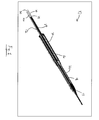
- a delivery catheter for the percutaneous delivery of plural segmented vascular stents, according to a first exemplary embodiment of the present invention.
- Delivery catheter 10 has a generally cylindrical central core 12 running along its axial length to a distal tip 14.
- a first stent 16 and second stent 18 are both placed over the central core 12 and each is radially compressed or crimped to a delivery diameter smaller than their deployed diameter.
- First stent 16 and second stent 18 are each surrounded by a sheath or pod 20, 22, that separates the stents 16, 18 from blood in the delivery vessel prior to deployment.
- Pods 20, 22 preferably join with one another to present a smooth outer diameter or transition. More preferably, pods 20, 22 are linked to one another to that the delivery catheter 10 may be rotated as a unit.
- stents 16, 18 are designed to and will be deployed to nest at least partially within one another.
- second stent 18 may be designed to nest at least partially within first stent 16.
- the first stent 16 is preferably deployed in the cranial or cephalid direction from the second stent 18.
- the second stent 18 is preferably crimped onto the central core 12 of delivery catheter 10 distally from the first stent 16. Accordingly, after deployment of the first stent 16, the delivery catheter 10 is moved in the caudal direction, or proximally, to position the second stent for deployment.
- Each pod 20, 22 has an independent release link, 24, 26, respectively.
- the release link 24, 26 may be a hollow, solid or braided filament of metal, or another material, including but not limited to plastic.
- the release links 24, 26 interface with their respective pods 20, 22 at a distal region of the delivery catheter 10, and extend to a proximal end of the delivery catheter 10 where they may be manipulated by the surgeon.
- the release links 24, 26 are bonded to their respective pods 20, 22 at proximal ends thereof.
- the first release link 24 is pulled by the surgeon to retract the first pod 20, exposing the first stent 16 to the vascular environment.
- the first link 24 may be attached to a handle at the proximal end of the delivery catheter 10, the surgeon pulling on the handle to retract the first pod 20.
- the first link 24 may be wound around a rotary handle at the proximal end of the delivery catheter 10, the surgeon rotating the rotary handle to retract the first pod 20.
- a combination of these two actions may independently manipulate the release links, for example a first release link 24 is activated by rotating the handle to wind the first link 24 around the handle.
- a second link 26 is connected to the same handle but not affected by the rotation thereof. However, an axial displacement of the handle may activate the second link 26.
- the first stent 16 expands to its deployed diameter, and engages the wall of the vessel in which it is deployed.
- the first stent 16 comprises a shape memory material which reacts to the heat of the vascular blood at body temperature by expanding to a deployed diameter.
- delivery catheter 10 preferably also comprises a cylindrical outer lumen (not shown) which can enclose the distal structure shown in Fig. 1 during insertion, and be retracted for deployment. Accordingly, the first pod 20 is retracted into the outer lumen when first stent 16 is deployed.
- the expansion of the stent 16 following the displacement of the pod 20 may be delayed by the prior application of a restraint holding the stent 16, 18 to the central core 12.
- the restraint may be released by degradation of the restraining material, appropriately selected from one those known for such a purpose.
- the restraint may be released by the severing the restraint.
- the first release link 24, or a separate dedicated release link may pass beneath the restraint and over the stent 16. Additional tension on the release link 24 following the displacement of pod 20 from over stent 16, or any tension on the separate release link dedicated for that purpose, would rupture the restraint, and free the stent 16 to expand to its deployed diameter.
- This delayed release arrangement will be seen as equally applicable to second stent 18, and optionally second release link 24 as discussed, infra.
- first pod 20 is withdrawn from over the first stent 16
- friction at the interface between the pod 20 and the stent 16 may be reduced by the application of a coating to the interior of the first pod 20.
- a coating may comprise silicone, MDX, or a hydrophilic material, among others suitable for the purpose.
- the first stent 16 can be coated for drug delivery. In that case, an anti-friction coating on an interior of the pod 20 can avoid removing stent coating during retraction of the pod 20 by friction between the pod 20 and the first stent 16.
- the release link 24 may run under the first pod 20 along some or all of its length. Applying tension to the release link 24 would pull the link through the material of the first pod 20, rupturing it, and release the pod 20 from around the first stent 16.
- the release link 24 could be bound to the material of the first pod 20 to draw it into an outer lumen as in the previous embodiment.
- the pod may comprise a bioabsorbable material, which disintegrates into the bloodstream after release.
- the pod material may be biocompatible and/or implantable, and be pressed between the exterior of stent 16 and the interior of the surrounding tissue without any negative implications. This deployment method has the advantage that it does not have to overcome friction between the pod 20 and the first stent 16.
- the delivery catheter 10 is repositioned by retracting it through the deployed first stent 16 in the proximal direction. Therefore, there is no risk of distal or cranial migration by interference with the delivery catheter 10.
- the second stent 18 is located in its deployment position.
- tension is applied to the second release link 26 to withdraw or alternately break through second pod 22, as described generally with respect to the first pod 20 and the release of the first stent 16.
- the second stent 18 is then free to expand to its deployed diameter within the vessel.
- the manner of releasing the second pod 22 may be by withdrawing the second pod 22 or breaking through the second pod 22, irrespective of the manner of releasing the first pod 20.
- the delivery catheter 10 is withdrawn in the proximal direction from within stents 16, 18 and the vessel in which they were deployed.
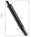
- FIG. 6 illustrates is a detail view of the delivery catheter 10 at the proximal end of first pod 20, in partial cutaway view.
- First stent 16, as well as first and second release links 24, 26 are visible.
- Pods 20 and 22 are preferably linked to one another so that the delivery catheter 10 may be rotated as a unit during insertion. Moreover, it is preferred that the transition between first pod 20 and second pod 22 be continuous on its outer surface to reduce resistance from the surrounding vessel upon insertion of the delivery catheter 10.
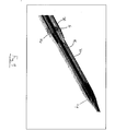
- Fig. 9 illustrated is the interface between the second pod 22 and the distal tip 12 of the delivery catheter 10. The interface between the second pod 22 and the distal tip 14 of the delivery catheter 10 is also preferably continuous, again to reduce resistance from the surrounding vessel on insertion.
- the delivery catheter 10 having a central lumen 28 for guide wire 30 will by recognized by those skilled in the art as an over-the-wire type configuration.
- the distal tip 12 of the delivery catheter 10 may include an abbreviated passage to accept the guide wire 30, as part of a so-called rapid-exchange design as is known in the art. Accordingly, the delivery catheter 10 need not be threaded over the entire length of the guide wire, and the guide wire can be shorter.
- using a rapid-exchange design obviates the need for a central lumen to admit the guide wire through all or most of its length. Accordingly, the overall diameter of the delivery catheter can be advantageously reduced.
- the size of the delivery catheter can be reduced to permit percutaneous insertion, eliminating the need for incision and the associated risks and drawbacks to the patient. Since the point of connection in the rapid-exchange design is distal of the pods 20, 22, the guide wire 30 would necessarily be outside the prosthesis after deployment, to be subsequently withdrawn.
- first pod 20 and first release link 24 can be dispensed with, and instead the outer lumen as described, supra, can maintain the first stent 16 in position before deployment. Then, the first stent 16 can be deployed by axially displacing the outer lumen with respect to the distal region of the delivery catheter 10, uncovering the first stent 16.
- the lumen itself extending from the proximal region of the delivery catheter 10 to the stent 16 can comprise both the pod and the link.
- an intermediate lumen may comprise both the pod and the link associated with the distal stent 18.
- a single delivery catheter delivers plural implants. This reduces the time required to perform the implantation procedure, reducing stress and trauma to the patient.
- the implantation is also simpler, requiring a single delivery catheter to deliver the plural implants.
- the implantation is also easier to perform, reducing the opportunity for errors and then demands on the skill of the surgeon.
- the delivery catheter 10 herein disclosed may be used to deliver fewer, or more particularly, more than two stents.
- Other applications for the present invention include the use of one or more stents to open an occluded vessel, commonly a coronary artery, particularly where a vessel may be subject to multiple blockages along its length.
- the present invention is applicable for the delivery of longer and/or serial stent grafts to other parts of the body, for example as used in the treatment of Superficial Femoral Artery aneurysm (SFA).
- SFA Superficial Femoral Artery aneurysm
- the terms 'stent' or 'stent graft' as used throughout the foregoing disclosure should be construed in a generic fashion, and encompass a variety of implantable medical devices, particularly tubular and/or prosthetic implants.
- the present invention is applicable for the delivery of shunts or vascular grafts not having stents.
Landscapes
- Health & Medical Sciences (AREA)
- Engineering & Computer Science (AREA)
- Biomedical Technology (AREA)
- Cardiology (AREA)
- Oral & Maxillofacial Surgery (AREA)
- Transplantation (AREA)
- Heart & Thoracic Surgery (AREA)
- Vascular Medicine (AREA)
- Life Sciences & Earth Sciences (AREA)
- Animal Behavior & Ethology (AREA)
- General Health & Medical Sciences (AREA)
- Public Health (AREA)
- Veterinary Medicine (AREA)
- Prostheses (AREA)
- Media Introduction/Drainage Providing Device (AREA)
Applications Claiming Priority (1)
| Application Number | Priority Date | Filing Date | Title |
|---|---|---|---|
| US11/343,626 US20070179586A1 (en) | 2006-01-31 | 2006-01-31 | Deployment catheter for medical implant devices |
Publications (2)
| Publication Number | Publication Date |
|---|---|
| EP1813232A1 true EP1813232A1 (fr) | 2007-08-01 |
| EP1813232B1 EP1813232B1 (fr) | 2009-08-26 |
Family
ID=37951816
Family Applications (1)
| Application Number | Title | Priority Date | Filing Date |
|---|---|---|---|
| EP07250339A Active EP1813232B1 (fr) | 2006-01-31 | 2007-01-27 | Déploiement de cathéter pour des dispositifs d'implant médical |
Country Status (6)
| Country | Link |
|---|---|
| US (1) | US20070179586A1 (fr) |
| EP (1) | EP1813232B1 (fr) |
| JP (1) | JP2007203048A (fr) |
| AT (1) | ATE440575T1 (fr) |
| CA (1) | CA2576373A1 (fr) |
| DE (1) | DE602007002072D1 (fr) |
Families Citing this family (5)
| Publication number | Priority date | Publication date | Assignee | Title |
|---|---|---|---|---|
| US20120238806A1 (en) | 2009-08-24 | 2012-09-20 | Quali-Med Gmbh | Implantation system with handle and catheter and method of use thereof |
| US9439652B2 (en) * | 2009-08-24 | 2016-09-13 | Qualimed Innovative Medizinprodukte Gmbh | Implantation device with handle and method of use thereof |
| US9999531B2 (en) | 2009-08-24 | 2018-06-19 | Qualimed Innovative Medizinprodukte Gmbh | Variable scale stent deployment device |
| EP3685807A1 (fr) | 2010-06-24 | 2020-07-29 | Cardinal Health Switzerland 515 GmbH | Appareil et procédé pour tirer un élément de traction à partir d'un dispositif médical |
| WO2021129285A1 (fr) * | 2019-12-23 | 2021-07-01 | 杭州唯强医疗科技有限公司 | Dispositif d'amenée et de libération d'endoprothèse et système d'amenée et de libération d'endoprothèse |
Citations (5)
| Publication number | Priority date | Publication date | Assignee | Title |
|---|---|---|---|---|
| WO1999043379A1 (fr) | 1998-02-26 | 1999-09-02 | Board Of Regents, The University Of Texas System | Systeme et procede de delivrance permettant le deploiement et l'assemblage endovasculaire d'un stent a greffer multi-etages |
| WO2000056248A1 (fr) | 1999-03-22 | 2000-09-28 | Scimed Life Systems, Inc. | Manchon lubrifie pour la mise en place de stents |
| US6183481B1 (en) | 1999-09-22 | 2001-02-06 | Endomed Inc. | Delivery system for self-expanding stents and grafts |
| US20020010419A1 (en) | 1997-09-18 | 2002-01-24 | Swaminathan Jayaraman | Delivery mechanism for balloons, drugs, stents and other physical/mechanical agents and method of use |
| US20020072789A1 (en) | 2000-12-12 | 2002-06-13 | Hackett Steven S. | Soc lubricant filler port |
Family Cites Families (6)
| Publication number | Priority date | Publication date | Assignee | Title |
|---|---|---|---|---|
| FR2688401B1 (fr) * | 1992-03-12 | 1998-02-27 | Thierry Richard | Endoprothese expansible pour organe tubulaire humain ou animal, et outil de mise en place. |
| US5707376A (en) * | 1992-08-06 | 1998-01-13 | William Cook Europe A/S | Stent introducer and method of use |
| US5476505A (en) * | 1993-11-18 | 1995-12-19 | Advanced Cardiovascular Systems, Inc. | Coiled stent and delivery system |
| US6352561B1 (en) * | 1996-12-23 | 2002-03-05 | W. L. Gore & Associates | Implant deployment apparatus |
| US6042588A (en) * | 1998-03-03 | 2000-03-28 | Scimed Life Systems, Inc | Stent delivery system |
| US6830575B2 (en) * | 2002-05-08 | 2004-12-14 | Scimed Life Systems, Inc. | Method and device for providing full protection to a stent |
-
2006
- 2006-01-31 US US11/343,626 patent/US20070179586A1/en not_active Abandoned
-
2007
- 2007-01-27 AT AT07250339T patent/ATE440575T1/de not_active IP Right Cessation
- 2007-01-27 DE DE602007002072T patent/DE602007002072D1/de active Active
- 2007-01-27 EP EP07250339A patent/EP1813232B1/fr active Active
- 2007-01-29 CA CA002576373A patent/CA2576373A1/fr not_active Abandoned
- 2007-01-30 JP JP2007019774A patent/JP2007203048A/ja not_active Withdrawn
Patent Citations (5)
| Publication number | Priority date | Publication date | Assignee | Title |
|---|---|---|---|---|
| US20020010419A1 (en) | 1997-09-18 | 2002-01-24 | Swaminathan Jayaraman | Delivery mechanism for balloons, drugs, stents and other physical/mechanical agents and method of use |
| WO1999043379A1 (fr) | 1998-02-26 | 1999-09-02 | Board Of Regents, The University Of Texas System | Systeme et procede de delivrance permettant le deploiement et l'assemblage endovasculaire d'un stent a greffer multi-etages |
| WO2000056248A1 (fr) | 1999-03-22 | 2000-09-28 | Scimed Life Systems, Inc. | Manchon lubrifie pour la mise en place de stents |
| US6183481B1 (en) | 1999-09-22 | 2001-02-06 | Endomed Inc. | Delivery system for self-expanding stents and grafts |
| US20020072789A1 (en) | 2000-12-12 | 2002-06-13 | Hackett Steven S. | Soc lubricant filler port |
Also Published As
| Publication number | Publication date |
|---|---|
| ATE440575T1 (de) | 2009-09-15 |
| JP2007203048A (ja) | 2007-08-16 |
| US20070179586A1 (en) | 2007-08-02 |
| DE602007002072D1 (de) | 2009-10-08 |
| EP1813232B1 (fr) | 2009-08-26 |
| CA2576373A1 (fr) | 2007-07-31 |
Similar Documents
| Publication | Publication Date | Title |
|---|---|---|
| EP1894545B1 (fr) | Dispositif de mise en place d'implants multiples in vivo | |
| AU2003248771B2 (en) | Thoracic stent-graft introducer | |
| US5713907A (en) | Apparatus and method for dilating a lumen and for inserting an intraluminal graft | |
| EP3031425B1 (fr) | Dispositif d'introduction pour un dispositif de ramification latérale iliaque | |
| US5749918A (en) | Intraluminal graft and method for inserting the same | |
| EP2387379B1 (fr) | Endoprothèse couverte et ensemble introducteur | |
| EP2317958B1 (fr) | Dispositif d'introduction dans le thorax | |
| EP2564812A1 (fr) | Ensemble de prothèse endoluminale | |
| WO2011008989A2 (fr) | Greffe dendoprothèse | |
| EP2007315A1 (fr) | Prothese avec lumiere de guidage | |
| US9456913B2 (en) | Implant introducer with helical trigger wire | |
| AU2021232667A1 (en) | Stent cannulation guiding device and method of use | |
| EP2586405B1 (fr) | Ensemble couvercle supérieur amovible | |
| EP1813232B1 (fr) | Déploiement de cathéter pour des dispositifs d'implant médical |
Legal Events
| Date | Code | Title | Description |
|---|---|---|---|
| PUAI | Public reference made under article 153(3) epc to a published international application that has entered the european phase |
Free format text: ORIGINAL CODE: 0009012 |
|
| AK | Designated contracting states |
Kind code of ref document: A1 Designated state(s): AT BE BG CH CY CZ DE DK EE ES FI FR GB GR HU IE IS IT LI LT LU LV MC NL PL PT RO SE SI SK TR |
|
| AX | Request for extension of the european patent |
Extension state: AL BA HR MK YU |
|
| 17P | Request for examination filed |
Effective date: 20080117 |
|
| 17Q | First examination report despatched |
Effective date: 20080225 |
|
| AKX | Designation fees paid |
Designated state(s): AT BE BG CH CY CZ DE DK EE ES FI FR GB GR HU IE IS IT LI LT LU LV MC NL PL PT RO SE SI SK TR |
|
| GRAP | Despatch of communication of intention to grant a patent |
Free format text: ORIGINAL CODE: EPIDOSNIGR1 |
|
| GRAS | Grant fee paid |
Free format text: ORIGINAL CODE: EPIDOSNIGR3 |
|
| GRAA | (expected) grant |
Free format text: ORIGINAL CODE: 0009210 |
|
| AK | Designated contracting states |
Kind code of ref document: B1 Designated state(s): AT BE BG CH CY CZ DE DK EE ES FI FR GB GR HU IE IS IT LI LT LU LV MC NL PL PT RO SE SI SK TR |
|
| REG | Reference to a national code |
Ref country code: GB Ref legal event code: FG4D |
|
| REG | Reference to a national code |
Ref country code: CH Ref legal event code: EP |
|
| REG | Reference to a national code |
Ref country code: IE Ref legal event code: FG4D |
|
| REF | Corresponds to: |
Ref document number: 602007002072 Country of ref document: DE Date of ref document: 20091008 Kind code of ref document: P |
|
| LTIE | Lt: invalidation of european patent or patent extension |
Effective date: 20090826 |
|
| PG25 | Lapsed in a contracting state [announced via postgrant information from national office to epo] |
Ref country code: SE Free format text: LAPSE BECAUSE OF FAILURE TO SUBMIT A TRANSLATION OF THE DESCRIPTION OR TO PAY THE FEE WITHIN THE PRESCRIBED TIME-LIMIT Effective date: 20090826 Ref country code: LT Free format text: LAPSE BECAUSE OF FAILURE TO SUBMIT A TRANSLATION OF THE DESCRIPTION OR TO PAY THE FEE WITHIN THE PRESCRIBED TIME-LIMIT Effective date: 20090826 Ref country code: FI Free format text: LAPSE BECAUSE OF FAILURE TO SUBMIT A TRANSLATION OF THE DESCRIPTION OR TO PAY THE FEE WITHIN THE PRESCRIBED TIME-LIMIT Effective date: 20090826 Ref country code: IS Free format text: LAPSE BECAUSE OF FAILURE TO SUBMIT A TRANSLATION OF THE DESCRIPTION OR TO PAY THE FEE WITHIN THE PRESCRIBED TIME-LIMIT Effective date: 20091226 Ref country code: AT Free format text: LAPSE BECAUSE OF FAILURE TO SUBMIT A TRANSLATION OF THE DESCRIPTION OR TO PAY THE FEE WITHIN THE PRESCRIBED TIME-LIMIT Effective date: 20090826 |
|
| PG25 | Lapsed in a contracting state [announced via postgrant information from national office to epo] |
Ref country code: PL Free format text: LAPSE BECAUSE OF FAILURE TO SUBMIT A TRANSLATION OF THE DESCRIPTION OR TO PAY THE FEE WITHIN THE PRESCRIBED TIME-LIMIT Effective date: 20090826 Ref country code: LV Free format text: LAPSE BECAUSE OF FAILURE TO SUBMIT A TRANSLATION OF THE DESCRIPTION OR TO PAY THE FEE WITHIN THE PRESCRIBED TIME-LIMIT Effective date: 20090826 Ref country code: SI Free format text: LAPSE BECAUSE OF FAILURE TO SUBMIT A TRANSLATION OF THE DESCRIPTION OR TO PAY THE FEE WITHIN THE PRESCRIBED TIME-LIMIT Effective date: 20090826 |
|
| PG25 | Lapsed in a contracting state [announced via postgrant information from national office to epo] |
Ref country code: CY Free format text: LAPSE BECAUSE OF FAILURE TO SUBMIT A TRANSLATION OF THE DESCRIPTION OR TO PAY THE FEE WITHIN THE PRESCRIBED TIME-LIMIT Effective date: 20090826 Ref country code: PT Free format text: LAPSE BECAUSE OF FAILURE TO SUBMIT A TRANSLATION OF THE DESCRIPTION OR TO PAY THE FEE WITHIN THE PRESCRIBED TIME-LIMIT Effective date: 20091228 Ref country code: BG Free format text: LAPSE BECAUSE OF FAILURE TO SUBMIT A TRANSLATION OF THE DESCRIPTION OR TO PAY THE FEE WITHIN THE PRESCRIBED TIME-LIMIT Effective date: 20091126 |
|
| PG25 | Lapsed in a contracting state [announced via postgrant information from national office to epo] |
Ref country code: DK Free format text: LAPSE BECAUSE OF FAILURE TO SUBMIT A TRANSLATION OF THE DESCRIPTION OR TO PAY THE FEE WITHIN THE PRESCRIBED TIME-LIMIT Effective date: 20090826 Ref country code: CZ Free format text: LAPSE BECAUSE OF FAILURE TO SUBMIT A TRANSLATION OF THE DESCRIPTION OR TO PAY THE FEE WITHIN THE PRESCRIBED TIME-LIMIT Effective date: 20090826 Ref country code: RO Free format text: LAPSE BECAUSE OF FAILURE TO SUBMIT A TRANSLATION OF THE DESCRIPTION OR TO PAY THE FEE WITHIN THE PRESCRIBED TIME-LIMIT Effective date: 20090826 Ref country code: ES Free format text: LAPSE BECAUSE OF FAILURE TO SUBMIT A TRANSLATION OF THE DESCRIPTION OR TO PAY THE FEE WITHIN THE PRESCRIBED TIME-LIMIT Effective date: 20091207 Ref country code: EE Free format text: LAPSE BECAUSE OF FAILURE TO SUBMIT A TRANSLATION OF THE DESCRIPTION OR TO PAY THE FEE WITHIN THE PRESCRIBED TIME-LIMIT Effective date: 20090826 |
|
| PG25 | Lapsed in a contracting state [announced via postgrant information from national office to epo] |
Ref country code: SK Free format text: LAPSE BECAUSE OF FAILURE TO SUBMIT A TRANSLATION OF THE DESCRIPTION OR TO PAY THE FEE WITHIN THE PRESCRIBED TIME-LIMIT Effective date: 20090826 |
|
| PG25 | Lapsed in a contracting state [announced via postgrant information from national office to epo] |
Ref country code: BE Free format text: LAPSE BECAUSE OF FAILURE TO SUBMIT A TRANSLATION OF THE DESCRIPTION OR TO PAY THE FEE WITHIN THE PRESCRIBED TIME-LIMIT Effective date: 20090826 |
|
| PLBE | No opposition filed within time limit |
Free format text: ORIGINAL CODE: 0009261 |
|
| STAA | Information on the status of an ep patent application or granted ep patent |
Free format text: STATUS: NO OPPOSITION FILED WITHIN TIME LIMIT |
|
| 26N | No opposition filed |
Effective date: 20100527 |
|
| PG25 | Lapsed in a contracting state [announced via postgrant information from national office to epo] |
Ref country code: MC Free format text: LAPSE BECAUSE OF NON-PAYMENT OF DUE FEES Effective date: 20100131 |
|
| PG25 | Lapsed in a contracting state [announced via postgrant information from national office to epo] |
Ref country code: GR Free format text: LAPSE BECAUSE OF FAILURE TO SUBMIT A TRANSLATION OF THE DESCRIPTION OR TO PAY THE FEE WITHIN THE PRESCRIBED TIME-LIMIT Effective date: 20091127 |
|
| PGRI | Patent reinstated in contracting state [announced from national office to epo] |
Ref country code: IT Effective date: 20110501 |
|
| REG | Reference to a national code |
Ref country code: CH Ref legal event code: PL |
|
| PG25 | Lapsed in a contracting state [announced via postgrant information from national office to epo] |
Ref country code: CH Free format text: LAPSE BECAUSE OF NON-PAYMENT OF DUE FEES Effective date: 20110131 Ref country code: LI Free format text: LAPSE BECAUSE OF NON-PAYMENT OF DUE FEES Effective date: 20110131 |
|
| PG25 | Lapsed in a contracting state [announced via postgrant information from national office to epo] |
Ref country code: LU Free format text: LAPSE BECAUSE OF NON-PAYMENT OF DUE FEES Effective date: 20100127 Ref country code: HU Free format text: LAPSE BECAUSE OF FAILURE TO SUBMIT A TRANSLATION OF THE DESCRIPTION OR TO PAY THE FEE WITHIN THE PRESCRIBED TIME-LIMIT Effective date: 20100227 |
|
| PG25 | Lapsed in a contracting state [announced via postgrant information from national office to epo] |
Ref country code: TR Free format text: LAPSE BECAUSE OF FAILURE TO SUBMIT A TRANSLATION OF THE DESCRIPTION OR TO PAY THE FEE WITHIN THE PRESCRIBED TIME-LIMIT Effective date: 20090826 |
|
| REG | Reference to a national code |
Ref country code: FR Ref legal event code: PLFP Year of fee payment: 10 |
|
| REG | Reference to a national code |
Ref country code: FR Ref legal event code: PLFP Year of fee payment: 11 |
|
| REG | Reference to a national code |
Ref country code: FR Ref legal event code: PLFP Year of fee payment: 12 |
|
| REG | Reference to a national code |
Ref country code: GB Ref legal event code: 732E Free format text: REGISTERED BETWEEN 20180614 AND 20180620 |
|
| REG | Reference to a national code |
Ref country code: DE Ref legal event code: R082 Ref document number: 602007002072 Country of ref document: DE Representative=s name: PROCK, THOMAS, DR., GB |
|
| REG | Reference to a national code |
Ref country code: NL Ref legal event code: PD Owner name: CARDINAL HEALTH SWITZERLAND 515 GMBH; CH Free format text: DETAILS ASSIGNMENT: CHANGE OF OWNER(S), ASSIGNMENT; FORMER OWNER NAME: CORDIS CORPORATION Effective date: 20200708 |
|
| REG | Reference to a national code |
Ref country code: GB Ref legal event code: 732E Free format text: REGISTERED BETWEEN 20201126 AND 20201202 |
|
| REG | Reference to a national code |
Ref country code: DE Ref legal event code: R082 Ref document number: 602007002072 Country of ref document: DE Representative=s name: PROCK, THOMAS, DR., GB Ref country code: DE Ref legal event code: R081 Ref document number: 602007002072 Country of ref document: DE Owner name: CARDINAL HEALTH SWITZERLAND 515 GMBH, CH Free format text: FORMER OWNER: CORDIS CORP., MIAMI LAKES, FLA., US |
|
| PGFP | Annual fee paid to national office [announced via postgrant information from national office to epo] |
Ref country code: IE Payment date: 20230127 Year of fee payment: 17 Ref country code: FR Payment date: 20230125 Year of fee payment: 17 |
|
| PGFP | Annual fee paid to national office [announced via postgrant information from national office to epo] |
Ref country code: IT Payment date: 20230120 Year of fee payment: 17 Ref country code: GB Payment date: 20230127 Year of fee payment: 17 Ref country code: DE Payment date: 20230127 Year of fee payment: 17 |
|
| PGFP | Annual fee paid to national office [announced via postgrant information from national office to epo] |
Ref country code: NL Payment date: 20230126 Year of fee payment: 17 |
|
| PGFP | Annual fee paid to national office [announced via postgrant information from national office to epo] |
Ref country code: NL Payment date: 20240126 Year of fee payment: 18 |
|
| PGFP | Annual fee paid to national office [announced via postgrant information from national office to epo] |
Ref country code: IE Payment date: 20240129 Year of fee payment: 18 |