EP1813010B1 - Design of the magnet and webs in interior permanent magent rotors - Google Patents
Design of the magnet and webs in interior permanent magent rotors Download PDFInfo
- Publication number
- EP1813010B1 EP1813010B1 EP05818503.4A EP05818503A EP1813010B1 EP 1813010 B1 EP1813010 B1 EP 1813010B1 EP 05818503 A EP05818503 A EP 05818503A EP 1813010 B1 EP1813010 B1 EP 1813010B1
- Authority
- EP
- European Patent Office
- Prior art keywords
- slots
- rotor
- slot
- rotor core
- magnet
- Prior art date
- Legal status (The legal status is an assumption and is not a legal conclusion. Google has not performed a legal analysis and makes no representation as to the accuracy of the status listed.)
- Expired - Lifetime
Links
Images


Classifications
-
- H—ELECTRICITY
- H02—GENERATION; CONVERSION OR DISTRIBUTION OF ELECTRIC POWER
- H02K—DYNAMO-ELECTRIC MACHINES
- H02K1/00—Details of the magnetic circuit
- H02K1/06—Details of the magnetic circuit characterised by the shape, form or construction
- H02K1/22—Rotating parts of the magnetic circuit
- H02K1/27—Rotor cores with permanent magnets
- H02K1/2706—Inner rotors
- H02K1/272—Inner rotors the magnetisation axis of the magnets being perpendicular to the rotor axis
- H02K1/274—Inner rotors the magnetisation axis of the magnets being perpendicular to the rotor axis the rotor consisting of two or more circumferentially positioned magnets
- H02K1/2753—Inner rotors the magnetisation axis of the magnets being perpendicular to the rotor axis the rotor consisting of two or more circumferentially positioned magnets the rotor consisting of magnets or groups of magnets arranged with alternating polarity
- H02K1/276—Magnets embedded in the magnetic core, e.g. interior permanent magnets [IPM]
-
- H—ELECTRICITY
- H02—GENERATION; CONVERSION OR DISTRIBUTION OF ELECTRIC POWER
- H02K—DYNAMO-ELECTRIC MACHINES
- H02K1/00—Details of the magnetic circuit
- H02K1/06—Details of the magnetic circuit characterised by the shape, form or construction
- H02K1/22—Rotating parts of the magnetic circuit
- H02K1/27—Rotor cores with permanent magnets
- H02K1/2706—Inner rotors
- H02K1/272—Inner rotors the magnetisation axis of the magnets being perpendicular to the rotor axis
- H02K1/274—Inner rotors the magnetisation axis of the magnets being perpendicular to the rotor axis the rotor consisting of two or more circumferentially positioned magnets
- H02K1/2753—Inner rotors the magnetisation axis of the magnets being perpendicular to the rotor axis the rotor consisting of two or more circumferentially positioned magnets the rotor consisting of magnets or groups of magnets arranged with alternating polarity
- H02K1/276—Magnets embedded in the magnetic core, e.g. interior permanent magnets [IPM]
- H02K1/2766—Magnets embedded in the magnetic core, e.g. interior permanent magnets [IPM] having a flux concentration effect
Definitions
- the present invention relates to a rotor for an interior permanent magnet (IPM) machine or motor or, more specifically, to a design of the magnet and webs in IPM rotors in multiphase synchronous motors.
- IPM interior permanent magnet
- IPM motors or machines generally include a stator with excitation windings and a rotor having embedded magnets, e.g., an interior permanent magnet rotor. These rotors allow permanent magnet synchronous motors to operate with constant power over a wide range of speeds. The magnitude of this range of speeds, i.e. the ratio of the maximum speed to the minimum over which the constant power is maintained depends on the ratio of the inductances along the two orthogonal axes -- one in the direction of the magnet flux referred to as the d axis and the other 90 electrical degrees from the d-axis, called the q-axis.
- US 6 225 724 B1 discloses a motor embedded with magnets having good properties and productivity.
- a rotor of this motor includes a rotor core with laminated rotor core plates punched out of an electromagnetic steel plate and studded with bonded magnets of a powdered permanent magnet material and a resin in groups of slits located in the rotor core for each pole of the rotor.
- An object of the invention is to provide a rotor design which addresses among other things mechanical stress during operation, flux leakage and/or cogging torque. This object is achieved with a rotor according to the claims.
- a rotor in accordance with one embodiment, includes a rotor core formed of webs defining a layout of the magnets in the rotor core.
- the rotor core has at least one layer of magnets forming a plurality of poles.
- Each pole includes a plurality of slots for holding a magnet, at least two ribs comprising web portions between the centerline slot and each wing slot, and a plurality of magnets arranged in corresponding slots.
- the slots have at least a centerline slot and two angled wing slots extending from a position at or around respective ends of the centerline slot towards an outer circumference of the rotor core.
- the rotor core may be cylindrical and formed of stacked metal lamination or powdered pressed metals.
- the wing slots may taper from a position at or around respective ends of the centerline slot towards an outer circumference of the rotor core.
- An amount each wing slot may be tapered may be configured to minimize resulting cogging while maximizing an average torque.
- the centerline slot may be two slots having a rib therebetween,
- the rotor core may include at least two layers of magnets comprising an inner layer and an outer layer, the inner layer being closer to a center of the rotor core.
- Each pole may include at least inner and outer pole layers.
- Each of the pole layers includes a plurality of slots for holding a magnet, the slots having at least a centerline slot and two angled wing slots extending from a position at or around respective ends of the centerline slot towards an outer circumference of the rotor core; at least two ribs comprising web portions between the centerline slot and each wing slot; and a plurality of magnets arranged in corresponding slots.
- the wing slots of the inner and outer pole layers may taper from a position at or around respective ends of respective centerline slots towards an outer circumference of the rotor core.
- the magnets may include at least a rectangular block magnet.
- Each wing slot may include two opposite sides extending towards an outer circumference of the rotor core, the two sides being nonparallel to each other.
- the layer of magnets may be arranged inside the rotor core around a periphery of the rotor core.
- a rotor in a further embodiment, includes a rotor core formed of webs defining a layout of the magnets in the rotor core.
- the rotor core has a plurality of poles. Each pole has a plurality of slots for holding a magnet, the slots having at least a centerline slot and two angled wing slots extending from a position at or around respective ends of the centerline slot and tapering towards an outer circumference of the rotor core; and a plurality of magnets arranged in corresponding slots.
- the rotor core may be cylindrical and formed of stacked metal lamination or powdered pressed metals.
- An amount each wing slot may be tapered may be configured to minimize resulting cogging while maximizing an average torque.
- the centerline slot may be two slots having a rib therebetween.
- Each pole may include at least inner and outer magnet layers.
- Each of the magnet layers may include a plurality of slots for holding a magnet, the slots having at least a centerline slot and two angled wing slots extending from a position at or around respective ends of the centerline slot and tapering towards an outer circumference of the rotor core; and a plurality of magnets arranged in corresponding slots.
- a rotor in yet a further embodiment, includes a rotor core formed of webs defining a layout of the magnets in the rotor core, the rotor core having a plurality of poles, each pole having a magnet with a centerline portion and two angled wing portions extending from a position at or around respective ends of the centerline portion towards an outer circumference of the rotor core, the magnet being segmented into at least three parts.
- the rotor core may be cylindrical and formed of stacked metal lamination or powdered pressed metals.
- Each pole may include inner and outer pole layers.
- Each pole layer may include a magnet shaped with a centerline portion and two angled wing portions extending from a position at or around respective ends of the centerline portion towards an outer circumference of the rotor core, the magnet being segmented into at least three parts.
- a design of the magnet and webs in IPM rotors is provided for use in motors or electric machines, such as multiphase synchronous motors.
- the IPM rotor may be configured to optimize the number of magnet segments and webs of material used to restrain the magnets against centrifugal forces, while keeping the mechanical stresses in the webs within acceptable design limits and minimizing the amount of leakage flux that is lost in the webs.
- IPM rotors are a subassembly of a permanent magnet synchronous multiphase motor. IPM rotors allow permanent magnet synchronous motors to operate with constant power over a wide range of speeds. The magnitude of this range of speeds, i.e., the ratio of the maximum speed to the minimum over which the constant power is maintained depends on the ratio of the inductances along the two orthogonal axes -- one in the direction of the magnet flux referred to as the d-axis and the other 90 electrical degrees from the d-axis, called the q-axis. The ratio of these inductances, Lq/Ld, can be increased by increasing the number of layers of magnets comprising each pole.
- a standard and simplest form of the IPM rotor is a six pole machine, which would include six (6) magnets equally spaced at sixty (60) degrees mechanical apart, where each of the magnets is set into a slot or cutout in the lamination near a periphery of the rotor.
- another layer of magnets can be placed at a smaller radius, closer to the center of rotor may be added. This results in at least twelve (12) magnets per rotor in a six (6) pole machine. Additional layers may be added to further increase the ratio of Lq/Ld with further improvements in the constant power range.
- An exemplary two-layer rotor design is described below with reference to Figs. 1-3 in which magnets, such as rectangular block magnets, may be used as the magnet shape. Other magnet shapes may also be employed in accordance with the rotor design, in a manner described herein.
- an IPM rotor may be held together as one piece, so webs of the steel lamination material are used to hold the rotor together and restrain the magnets and lamination against centrifugal forces which result in both tangential hoop stresses as well as radial stresses in the webs of material.
- the webs provide leakage paths for the magnet flux, so the webs need to be as thin as possible to minimize the flux leakage. The following design approaches may be employed to address the above issues.
- an outermost layer of magnets of a rotor may be made to be thinner, in the radial direction, than the next inner layer toward the center and this can be continued as more layers are used. This allows the stresses in the webs of material restraining this magnet to be kept within acceptable limits and the thickness of the web required to be minimized, thereby minimizing the flux leakage.
- the magnets for a pole in the innermost layer may be split widthwise into two magnets (they could also be split into 3 or 4 segments widthwise as well), using webs of material between them in a direction ranging from parallel to the sides of the magnet to along the radial direction, to keep the web stresses within design limits while minimizing the flux leakage. This was found to be more necessary at the inner layer as compared to the outer layer, since the inner layers must carry the loads of the that layer plus the layers radically outward from that layer.
- the wing slots may be tapered to reduce the cogging torque.
- Each magnet layer may have three regions: an inner region on either side of the poles centerline, and two outer regions (e.g., the wing slots) that extend from the inner section's outer edges to the rotor's outer diameter (OD). Rather than these wing slots having parallel sides, they should have nonparallel sides tapering from wider where they meet with the inner region to narrower near the rotor's OD. This has the very beneficial effect of greatly reducing the unwanted reluctance torque variation with rotor position (cogging) at the cost of a small reduction in the average torque.
- the amount of tapering in the wing magnet can be optimized to minimize the resulting cogging torque while maintaining the motor's average torque as high as possible.
- FIG. 1 there is provided an exemplary IPM rotor 100 having a plurality of poles, e.g., six (6) poles.
- the IPM rotor 100 includes a rotor core 102 which can be formed of webs of lamination, such as steel laminations.
- the rotor 100 includes a plurality of magnet layers, such as an inner layer 110 and an outer layer 120 arranged in a periphery of the rotor 100.
- Each layers 110, 120 includes a plurality of slots and magnets arranged in a desired p attern.
- the inner layer 110 is arranged around an inner radius closer to a center of the rotor 100, and the outer layer 120 is arranged around an outer radius, farther from the center of the rotor 100, than the inner layer.
- each pole of the rotor 100 may include an inner pole layer 200 which is part of the inner layer 110, and an outer pole layer 250 which is part of the outer layer 120.
- the inner pole layer 200 includes a centerline slot 210 and two wing slots 212 which extend from a position at or around opposite ends (or edges), respectively, of the centerline slot 210 towards an outer circumference or surface of the rotor core 102.
- each wing slot 212 extends at an angle from a position at or around a respective end of the centerline slot 210.
- the centerline slot 210 may also be further segmented, as shown, to provide slots 210A and 210B.
- the slots 210A and 210B may be of equal or approximately equal dimensions or size.
- the web material between each slot forms a rib which provide for addition stress reduction or restraint of the magnets and rotor components due to centrifugal forces, as noted above.
- the inner pole layer 200 has ribs 222 between each end of wing slot 212 adjacent to a respective end of the centerline slot 210, and a rib 220 between two segments or slots 210A, 210B of the centerline slot 210.
- the ribs may be parallel or radial to the ends, sides or edges of the slots or magnets.
- the inner pole layer 210 may segment the magnet to provide for multiple ribs, e.g., two (2), three (3) or more, to provide for additional stress reduction or additional restraint of the magnets and rotor components, while balancing the flux leakage.
- Each wing slot 212 may also be tapered as the slot extends from an end of the centerline slot 210 towards the outer circumference or surface of the rotor core 102. This tapering may be provided by configuring the sides of the slot and/or the magnet extending towards the outer circumference or surface of the rotor core 102 to be unparallel. As discussed above, this has the very beneficial effect of greatly reducing the unwanted reluctance torque variation with rotor position (cogging) at the cost of a small reduction in the average torque.
- the amount of tapering in the wing magnet or slot or segment can be optimized to minimize the resulting cogging torque while maintaining the motor's average torque as high as possible. For example, wing slot 212 may taper to approximately half the width (versus the width at or around the centerline).
- a magnet 230 such as a rectangular block magnet, is arranged or embedded into slot 210B. This is simply provided as an example showing that magnets, of desired shapes, e.g., block magnets, rectangular block magnets, tapered block magnets, etc., are provided or embedded in the slots of the rotor 100.
- the inner pole layer 200 may be segmented into any number of magnet segments to provide for any number of ribs, and the magnet segments may be shaped accordingly.
- the inner pole layer 200 may have a trapezoidal- or U-shape.
- the outer pole layer 250 includes a centerline slot 260 and two wing slots 262 which extend from a position at or around opposite ends (or edges), respectively, of the centerline slot 260 towards an outer circumference or diameter of the rotor core 102.
- each wing slot 262 extends at an angle from a position at or around respective ends of the centerline slot 260.
- the centerline slot 260 may also be further segmented.
- the web material between each slot forms a rib which provide for addition stress reduction or restraint of the magnets and rotor components due to centrifugal forces, as noted above.
- the outer pole layer 250 has ribs 272 between each end of wing slot 262 adjacent to a respective end of the centerline slot 260.
- the ribs may be parallel or radial to the ends, sides or edges of the slots or magnets.
- the outer pole layer 250 may segment the magnet to provide for multiple ribs, e.g., two (2), three (3) or more, to provide for additional stress reduction or additional restraint of the magnets and rotor components, while balancing the flux leakage.
- Each wing slot 262 may also be tapered as the slot extends from an end of the centerline slot 260 towards the outer circumference or surface of the rotor core 102. This tapering may be provided by configuring the sides of the slot and/or the magnet extending towards the outer circumference or surface of the rotor core 102 to be unparallel. As discussed above, this has the very beneficial effect of greatly reducing the unwanted reluctance torque variation with rotor position (cogging) at the cost of a small reduction in the average torque.
- the amount of tapering in the wing magnet or slot or segment can be optimized to minimize the resulting cogging torque while maintaining the motor's average torque as high as possible. For example, wing slot 262 may taper to approximately half the width (versus at or around the centerline).
- each of the slots may have a magnet, such as a rectangular block magnet, arranged or embedded therein.
- the magnets may take any desired shape, e.g., block magnets, rectangular block magnets, tapered block magnets, etc.
- the outer pole layer 250 may be segmented into any number of magnet segments to provide for any number of ribs, and the magnet segments may be shaped accordingly.
- the outer pole layer 250 may have a trapezoidal- or U-shape.
- a rotor core slot provided by way of example as a slot 300 may be configured with radiused undercuts, such as a fillet or radius or the like, at an end(s) of the slot to reduce stress or for stress reduction during operation.
- the centerline slot(s) may be configured with such a fillet or radius. Any of the slots of rotor core 102 may have such fillets or radii or the like, as desired.
- the above rotor configuration of Figs. 1-3 describes one example of an IPM rotor with six (6) poles and two magnet layers.
- the rotor 110 may however include any number of poles, and/or any number of magnet layers and/or any number of pole layers per pole and/or any number of magnet segments or ribs per pole, layer or pole layer.
- additional layers may also be added to further increase the ratio of Lq/Ld with further improvements in the constant power range.
- the rotor core 102 may be cylindrical or shaped as desired and formed of stacked metal lamination or powdered pressed metals.
Landscapes
- Engineering & Computer Science (AREA)
- Power Engineering (AREA)
- Permanent Field Magnets Of Synchronous Machinery (AREA)
Description
- The present invention relates to a rotor for an interior permanent magnet (IPM) machine or motor or, more specifically, to a design of the magnet and webs in IPM rotors in multiphase synchronous motors.
- IPM motors or machines generally include a stator with excitation windings and a rotor having embedded magnets, e.g., an interior permanent magnet rotor. These rotors allow permanent magnet synchronous motors to operate with constant power over a wide range of speeds. The magnitude of this range of speeds, i.e. the ratio of the maximum speed to the minimum over which the constant power is maintained depends on the ratio of the inductances along the two orthogonal axes -- one in the direction of the magnet flux referred to as the d axis and the other 90 electrical degrees from the d-axis, called the q-axis.
- In designing such motors, various factors need to be addressed including among other things mechanical stress during operation, flux leakage and/or cogging torque.
-
US 6 225 724 B1 discloses a motor embedded with magnets having good properties and productivity. A rotor of this motor includes a rotor core with laminated rotor core plates punched out of an electromagnetic steel plate and studded with bonded magnets of a powdered permanent magnet material and a resin in groups of slits located in the rotor core for each pole of the rotor. - An object of the invention is to provide a rotor design which addresses among other things mechanical stress during operation, flux leakage and/or cogging torque. This object is achieved with a rotor according to the claims.
- In accordance with one embodiment, a rotor includes a rotor core formed of webs defining a layout of the magnets in the rotor core. The rotor core has at least one layer of magnets forming a plurality of poles. Each pole includes a plurality of slots for holding a magnet, at least two ribs comprising web portions between the centerline slot and each wing slot, and a plurality of magnets arranged in corresponding slots. The slots have at least a centerline slot and two angled wing slots extending from a position at or around respective ends of the centerline slot towards an outer circumference of the rotor core. The rotor core may be cylindrical and formed of stacked metal lamination or powdered pressed metals.
- The wing slots may taper from a position at or around respective ends of the centerline slot towards an outer circumference of the rotor core. An amount each wing slot may be tapered may be configured to minimize resulting cogging while maximizing an average torque.
- The centerline slot may be two slots having a rib therebetween, The rotor core may include at least two layers of magnets comprising an inner layer and an outer layer, the inner layer being closer to a center of the rotor core.
- Each pole may include at least inner and outer pole layers. Each of the pole layers includes a plurality of slots for holding a magnet, the slots having at least a centerline slot and two angled wing slots extending from a position at or around respective ends of the centerline slot towards an outer circumference of the rotor core; at least two ribs comprising web portions between the centerline slot and each wing slot; and a plurality of magnets arranged in corresponding slots. The wing slots of the inner and outer pole layers may taper from a position at or around respective ends of respective centerline slots towards an outer circumference of the rotor core.
- The magnets may include at least a rectangular block magnet. Each wing slot may include two opposite sides extending towards an outer circumference of the rotor core, the two sides being nonparallel to each other. The layer of magnets may be arranged inside the rotor core around a periphery of the rotor core.
- In a further embodiment, a rotor includes a rotor core formed of webs defining a layout of the magnets in the rotor core. The rotor core has a plurality of poles. Each pole has a plurality of slots for holding a magnet, the slots having at least a centerline slot and two angled wing slots extending from a position at or around respective ends of the centerline slot and tapering towards an outer circumference of the rotor core; and a plurality of magnets arranged in corresponding slots. The rotor core may be cylindrical and formed of stacked metal lamination or powdered pressed metals.
- An amount each wing slot may be tapered may be configured to minimize resulting cogging while maximizing an average torque. The centerline slot may be two slots having a rib therebetween.
- Each pole may include at least inner and outer magnet layers. Each of the magnet layers may include a plurality of slots for holding a magnet, the slots having at least a centerline slot and two angled wing slots extending from a position at or around respective ends of the centerline slot and tapering towards an outer circumference of the rotor core; and a plurality of magnets arranged in corresponding slots.
- In yet a further embodiment, a rotor includes a rotor core formed of webs defining a layout of the magnets in the rotor core, the rotor core having a plurality of poles, each pole having a magnet with a centerline portion and two angled wing portions extending from a position at or around respective ends of the centerline portion towards an outer circumference of the rotor core, the magnet being segmented into at least three parts. The rotor core may be cylindrical and formed of stacked metal lamination or powdered pressed metals.
- Each pole may include inner and outer pole layers. Each pole layer may include a magnet shaped with a centerline portion and two angled wing portions extending from a position at or around respective ends of the centerline portion towards an outer circumference of the rotor core, the magnet being segmented into at least three parts.
-
-
Fig. 1 illustrates and exemplary IPM rotor; -
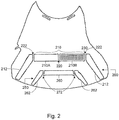
Fig. 2 illustrates a partial view of the exemplary rotor ofFig. 1 showing a pole; and -
Fig. 3 illustrates a partial view of the exemplary rotor ofFig. 1 showing a stress relieving configuration of a magnet slot. - In accordance with various aspects, a design of the magnet and webs in IPM rotors is provided for use in motors or electric machines, such as multiphase synchronous motors. As will be described in greater detail below, the IPM rotor may be configured to optimize the number of magnet segments and webs of material used to restrain the magnets against centrifugal forces, while keeping the mechanical stresses in the webs within acceptable design limits and minimizing the amount of leakage flux that is lost in the webs.
- IPM rotors are a subassembly of a permanent magnet synchronous multiphase motor. IPM rotors allow permanent magnet synchronous motors to operate with constant power over a wide range of speeds. The magnitude of this range of speeds, i.e., the ratio of the maximum speed to the minimum over which the constant power is maintained depends on the ratio of the inductances along the two orthogonal axes -- one in the direction of the magnet flux referred to as the d-axis and the other 90 electrical degrees from the d-axis, called the q-axis. The ratio of these inductances, Lq/Ld, can be increased by increasing the number of layers of magnets comprising each pole.
- For example, a standard and simplest form of the IPM rotor is a six pole machine, which would include six (6) magnets equally spaced at sixty (60) degrees mechanical apart, where each of the magnets is set into a slot or cutout in the lamination near a periphery of the rotor. To increase the Lq/Ld ratio, another layer of magnets can be placed at a smaller radius, closer to the center of rotor may be added. This results in at least twelve (12) magnets per rotor in a six (6) pole machine. Additional layers may be added to further increase the ratio of Lq/Ld with further improvements in the constant power range. An exemplary two-layer rotor design is described below with reference to
Figs. 1-3 in which magnets, such as rectangular block magnets, may be used as the magnet shape. Other magnet shapes may also be employed in accordance with the rotor design, in a manner described herein. - In one aspect, an IPM rotor may be held together as one piece, so webs of the steel lamination material are used to hold the rotor together and restrain the magnets and lamination against centrifugal forces which result in both tangential hoop stresses as well as radial stresses in the webs of material. In another aspect, the webs provide leakage paths for the magnet flux, so the webs need to be as thin as possible to minimize the flux leakage. The following design approaches may be employed to address the above issues.
- For example, in one exemplary approach, an outermost layer of magnets of a rotor may be made to be thinner, in the radial direction, than the next inner layer toward the center and this can be continued as more layers are used. This allows the stresses in the webs of material restraining this magnet to be kept within acceptable limits and the thickness of the web required to be minimized, thereby minimizing the flux leakage.
- In another exemplary approach, the magnets for a pole in the innermost layer may be split widthwise into two magnets (they could also be split into 3 or 4 segments widthwise as well), using webs of material between them in a direction ranging from parallel to the sides of the magnet to along the radial direction, to keep the web stresses within design limits while minimizing the flux leakage. This was found to be more necessary at the inner layer as compared to the outer layer, since the inner layers must carry the loads of the that layer plus the layers radically outward from that layer.
- To address another issue when designing an IPM rotor, the wing slots may be tapered to reduce the cogging torque. Each magnet layer may have three regions: an inner region on either side of the poles centerline, and two outer regions (e.g., the wing slots) that extend from the inner section's outer edges to the rotor's outer diameter (OD). Rather than these wing slots having parallel sides, they should have nonparallel sides tapering from wider where they meet with the inner region to narrower near the rotor's OD. This has the very beneficial effect of greatly reducing the unwanted reluctance torque variation with rotor position (cogging) at the cost of a small reduction in the average torque. The amount of tapering in the wing magnet can be optimized to minimize the resulting cogging torque while maintaining the motor's average torque as high as possible.
- An exemplary IPM rotor will be described below with reference to
Figs. 1-3 . As show inFig. 1 , there is provided anexemplary IPM rotor 100 having a plurality of poles, e.g., six (6) poles. TheIPM rotor 100 includes arotor core 102 which can be formed of webs of lamination, such as steel laminations. - The
rotor 100 includes a plurality of magnet layers, such as aninner layer 110 and anouter layer 120 arranged in a periphery of therotor 100. Each layers 110, 120 includes a plurality of slots and magnets arranged in a desired p attern. Theinner layer 110 is arranged around an inner radius closer to a center of therotor 100, and theouter layer 120 is arranged around an outer radius, farther from the center of therotor 100, than the inner layer. - As shown in
Fig. 2 , each pole of therotor 100 may include aninner pole layer 200 which is part of theinner layer 110, and anouter pole layer 250 which is part of theouter layer 120. - The
inner pole layer 200 includes acenterline slot 210 and twowing slots 212 which extend from a position at or around opposite ends (or edges), respectively, of thecenterline slot 210 towards an outer circumference or surface of therotor core 102. In this example, eachwing slot 212 extends at an angle from a position at or around a respective end of thecenterline slot 210. Thecenterline slot 210 may also be further segmented, as shown, to provideslots slots - As shown, the web material between each slot forms a rib which provide for addition stress reduction or restraint of the magnets and rotor components due to centrifugal forces, as noted above. In this example, the
inner pole layer 200 hasribs 222 between each end ofwing slot 212 adjacent to a respective end of thecenterline slot 210, and arib 220 between two segments orslots centerline slot 210. The ribs may be parallel or radial to the ends, sides or edges of the slots or magnets. Theinner pole layer 210 may segment the magnet to provide for multiple ribs, e.g., two (2), three (3) or more, to provide for additional stress reduction or additional restraint of the magnets and rotor components, while balancing the flux leakage. - Each
wing slot 212 may also be tapered as the slot extends from an end of thecenterline slot 210 towards the outer circumference or surface of therotor core 102. This tapering may be provided by configuring the sides of the slot and/or the magnet extending towards the outer circumference or surface of therotor core 102 to be unparallel. As discussed above, this has the very beneficial effect of greatly reducing the unwanted reluctance torque variation with rotor position (cogging) at the cost of a small reduction in the average torque. The amount of tapering in the wing magnet or slot or segment can be optimized to minimize the resulting cogging torque while maintaining the motor's average torque as high as possible. For example,wing slot 212 may taper to approximately half the width (versus the width at or around the centerline). - A
magnet 230, such as a rectangular block magnet, is arranged or embedded intoslot 210B. This is simply provided as an example showing that magnets, of desired shapes, e.g., block magnets, rectangular block magnets, tapered block magnets, etc., are provided or embedded in the slots of therotor 100. - Although in the
inner pole layer 200 employs a magnet segmented into four (4) segments, theinner pole layer 200 may be segmented into any number of magnet segments to provide for any number of ribs, and the magnet segments may be shaped accordingly. For example, theinner pole layer 200 may have a trapezoidal- or U-shape. - The
outer pole layer 250 includes acenterline slot 260 and twowing slots 262 which extend from a position at or around opposite ends (or edges), respectively, of thecenterline slot 260 towards an outer circumference or diameter of therotor core 102. In this example, eachwing slot 262 extends at an angle from a position at or around respective ends of thecenterline slot 260. As with theinner pole layer 200, thecenterline slot 260 may also be further segmented. - As shown, the web material between each slot forms a rib which provide for addition stress reduction or restraint of the magnets and rotor components due to centrifugal forces, as noted above. In this example, the
outer pole layer 250 hasribs 272 between each end ofwing slot 262 adjacent to a respective end of thecenterline slot 260. The ribs may be parallel or radial to the ends, sides or edges of the slots or magnets. Theouter pole layer 250 may segment the magnet to provide for multiple ribs, e.g., two (2), three (3) or more, to provide for additional stress reduction or additional restraint of the magnets and rotor components, while balancing the flux leakage. - Each
wing slot 262 may also be tapered as the slot extends from an end of thecenterline slot 260 towards the outer circumference or surface of therotor core 102. This tapering may be provided by configuring the sides of the slot and/or the magnet extending towards the outer circumference or surface of therotor core 102 to be unparallel. As discussed above, this has the very beneficial effect of greatly reducing the unwanted reluctance torque variation with rotor position (cogging) at the cost of a small reduction in the average torque. The amount of tapering in the wing magnet or slot or segment can be optimized to minimize the resulting cogging torque while maintaining the motor's average torque as high as possible. For example,wing slot 262 may taper to approximately half the width (versus at or around the centerline). - As with the
inner pole layer 200, each of the slots may have a magnet, such as a rectangular block magnet, arranged or embedded therein. The magnets may take any desired shape, e.g., block magnets, rectangular block magnets, tapered block magnets, etc. - Although in the
outer pole layer 250 employs a magnet segmented into four (3) segments, theouter pole layer 250 may be segmented into any number of magnet segments to provide for any number of ribs, and the magnet segments may be shaped accordingly. For example, theouter pole layer 250 may have a trapezoidal- or U-shape. - Turning to
Fig. 3 , a rotor core slot provided by way of example as aslot 300 may be configured with radiused undercuts, such as a fillet or radius or the like, at an end(s) of the slot to reduce stress or for stress reduction during operation. As shown in the examples ofFigs. 1-3 , the centerline slot(s) may be configured with such a fillet or radius. Any of the slots ofrotor core 102 may have such fillets or radii or the like, as desired. - The above rotor configuration of
Figs. 1-3 describes one example of an IPM rotor with six (6) poles and two magnet layers. Therotor 110 may however include any number of poles, and/or any number of magnet layers and/or any number of pole layers per pole and/or any number of magnet segments or ribs per pole, layer or pole layer. As described above, additional layers may also be added to further increase the ratio of Lq/Ld with further improvements in the constant power range. Further, therotor core 102 may be cylindrical or shaped as desired and formed of stacked metal lamination or powdered pressed metals. - While various embodiments of the present invention have been described above, it should be understood that they have been presented by way of example only, and not in limitation. Accordingly, it will be apparent to persons skilled in the relevant art that various changes in form and detail can be made therein without departing from the scope of the invention. Thus, the breadth and scope of the present invention should not be limited by any of the above-described exemplary embodiments, but should be defined only in accordance with the following claims and their equivalents. Thus, other network types are within the scope of the present invention.
Claims (12)
- A rotor comprising:a rotor core (102) formed of webs defining a layout of the magnets in the rotor core, the rotor core having a plurality of poles, each pole having:a plurality of slots for holding a magnet, the slots having at least a centerline slot (210, 260) and two angled wing slots (212, 262) extending from a position at or around respective ends of the centerline slot and tapering towards an outer circumference of the rotor core, anda plurality of magnets (230) arranged in corresponding slots.
- The rotor of claim 1, wherein:the rotor core (102) has at least one layer (110, 120) of magnets forming said plurality of poles,each pole including at least two ribs (220, 222) comprising web portions between the centerline slot and each wing slot, and
- The rotor according to claim 2, wherein the rotor core (102) includes at least two layers of magnets comprising an inner layer (110) and an outer layer (120), the inner layer being closer to a center of the rotor core.
- The rotor according to claim 2, wherein each pole includes at least inner (200) and outer (250) pole layers, each of the pole layers comprising:a plurality of slots for holding a magnet, the slots having at least a centerline slot (210, 260) and two angled wing slots (212, 262) extending from a position, at or around respective ends of the centerline slot towards an outer circumference of the rotor core (102),at least two ribs (220, 222) comprising web portions between the centerline slot and each wing slot, anda plurality of magnets (230) arranged in corresponding slots.
- The rotor according to claim 4, wherein the wing slots (212, 262) of the inner and outer pole layers taper from a position at or around respective ends of respective centerline slots (210, 260) towards an outer circumference of the rotor core (102).
- The rotor according to claim 2, wherein the magnets (230) includes at least a rectangular block magnet.
- The rotor according to claim 2, wherein each wing slot includes two opposite sides extending towards an outer circumference of the rotor core, the two sides being nonparallel to each other.
- The rotor according to claim 2, wherein the layer of magnets are arranged inside the rotor core (102) around a periphery of the rotor core (102).
- The rotor according to claim 1, wherein an amount each wing slot (212, 262) is tapered is configured to minimize resulting cogging while maximizing an average torque.
- The rotor according to claim 1 or 2, wherein the centerline slot (201, 260) further comprises two slots (210A, 210B) having a rib therebetween.
- The rotor according to claim 1, wherein each pole includes at least inner and outer magnet layers, each of the magnet layers comprising:a plurality of slots for holding a magnet, the slots having at least a centerline slot and two angled wing slots extending from a position at or around respective ends of the centerline slot and tapering towards an outer circumference of the rotor core, anda plurality of magnets arranged in corresponding slots.
- A motor comprising a rotor according to claim 1.
Applications Claiming Priority (2)
| Application Number | Priority Date | Filing Date | Title |
|---|---|---|---|
| US62229004P | 2004-10-26 | 2004-10-26 | |
| PCT/US2005/038374 WO2006047519A2 (en) | 2004-10-26 | 2005-10-26 | Design of the magnet and webs in interior permanent magent rotors |
Publications (3)
| Publication Number | Publication Date |
|---|---|
| EP1813010A2 EP1813010A2 (en) | 2007-08-01 |
| EP1813010A4 EP1813010A4 (en) | 2016-08-03 |
| EP1813010B1 true EP1813010B1 (en) | 2018-01-24 |
Family
ID=36228384
Family Applications (1)
| Application Number | Title | Priority Date | Filing Date |
|---|---|---|---|
| EP05818503.4A Expired - Lifetime EP1813010B1 (en) | 2004-10-26 | 2005-10-26 | Design of the magnet and webs in interior permanent magent rotors |
Country Status (4)
| Country | Link |
|---|---|
| US (1) | US7498708B2 (en) |
| EP (1) | EP1813010B1 (en) |
| JP (1) | JP5059614B2 (en) |
| WO (1) | WO2006047519A2 (en) |
Cited By (1)
| Publication number | Priority date | Publication date | Assignee | Title |
|---|---|---|---|---|
| EP4012893A1 (en) * | 2020-12-10 | 2022-06-15 | Volvo Car Corporation | Electric machine |
Families Citing this family (34)
| Publication number | Priority date | Publication date | Assignee | Title |
|---|---|---|---|---|
| JP2005341655A (en) * | 2004-05-24 | 2005-12-08 | Denso Corp | Rotor of magnet-embedded rotary electric machine |
| US7436096B2 (en) * | 2005-10-31 | 2008-10-14 | Caterpillar Inc. | Rotor having permanent magnets and axialy-extending channels |
| US20070159021A1 (en) | 2005-12-19 | 2007-07-12 | Emerson Electric Co. | Composite magnet structure for rotor |
| US7816830B2 (en) * | 2007-08-16 | 2010-10-19 | Gary Dickes | Permanent magnet alternator with segmented construction |
| DE102007040750A1 (en) * | 2007-08-28 | 2009-03-05 | Brusa Elektronik Ag | Electrically excited synchronous motor, in particular for vehicle drives |
| US20090224624A1 (en) * | 2008-03-06 | 2009-09-10 | Ajith Kuttannair Kumar | Rotor structure for interior permanent magnet electromotive machine |
| US7902711B2 (en) * | 2008-12-09 | 2011-03-08 | GM Global Technology Operations LLC | Methods and apparatus for a permanent magnet machine with segmented ferrite magnets |
| WO2011033397A2 (en) | 2009-09-18 | 2011-03-24 | Brusa Elektronik Ag | Permanent magnet exited synchronous machine with embedded magnets |
| JP2013531462A (en) * | 2010-07-09 | 2013-08-01 | ブルサ エレクトロニック アーゲー | Laminated rotor for rotating a hybrid synchronous motor of an electric machine, particularly a vehicle drive system |
| US20120074801A1 (en) * | 2010-09-27 | 2012-03-29 | Kollmorgen Corporation | Magnetic Rotor Having Inset Bridges To Promote Cooling |
| US8618708B2 (en) | 2011-07-29 | 2013-12-31 | General Electric Company | Electrical machine |
| JP5755336B2 (en) * | 2011-10-26 | 2015-07-29 | 三菱電機株式会社 | Rotor and permanent magnet embedded motor |
| US8860275B2 (en) * | 2011-12-09 | 2014-10-14 | GM Global Technology Operations LLC | Multi-layer arc-shaped permanent magnet machine with reduced rotational stress |
| CN102761222B (en) * | 2012-03-05 | 2013-08-07 | 珠海格力节能环保制冷技术研究中心有限公司 | Permanent-magnet-aided synchronous reluctance motor, rotor of motor and mounting method of motor |
| US20130249342A1 (en) * | 2012-03-20 | 2013-09-26 | Kollmorgen Corporation | Cantilevered Rotor Magnet Support |
| US20130249345A1 (en) * | 2012-03-22 | 2013-09-26 | GM Global Technology Operations LLC | Segmented rotor in a rotor assembly |
| US9035520B2 (en) | 2012-05-24 | 2015-05-19 | Kollmorgen Corporation | Rotor lamination stress relief |
| FR2995469B1 (en) | 2012-09-13 | 2017-04-21 | Moteurs Leroy-Somer | ROTOR OF ROTATING ELECTRIC MACHINE HAVING A ROTORIC MASS IN WHICH ARE HOUSEHOLDS. |
| US9641054B2 (en) | 2013-05-17 | 2017-05-02 | General Electric Company | Segmented magnet component for electric machine and method of assembly |
| ITUB20150608A1 (en) * | 2015-04-14 | 2016-10-14 | Ge Avio Srl | METHOD OF REALIZATION OF A ROTOR STRUCTURE OF A SYNCHRONOUS RELUCTANCE ELECTRIC MACHINE, AND RELATED RELUCTANCE SYNCHRONOUS ELECTRICAL MACHINE |
| KR20170050079A (en) * | 2015-10-29 | 2017-05-11 | (주)지이엠 | Motor With Notched Rotor For Cogging Torque Reduction |
| GB2551537A (en) | 2016-06-21 | 2017-12-27 | Jaguar Land Rover Ltd | Electrical machine |
| DE102017222683A1 (en) * | 2017-12-13 | 2019-06-13 | Baumüller Nürnberg GmbH | Electric machine |
| CN108321952B (en) * | 2018-03-16 | 2020-10-16 | 珠海格力节能环保制冷技术研究中心有限公司 | Rotor structure, permanent magnet auxiliary synchronous reluctance motor and electric automobile |
| CN108321955B (en) * | 2018-03-16 | 2020-10-23 | 珠海格力节能环保制冷技术研究中心有限公司 | Rotor structure, permanent magnet auxiliary synchronous reluctance motor and electric automobile |
| CN108390483B (en) * | 2018-03-16 | 2020-12-15 | 珠海格力节能环保制冷技术研究中心有限公司 | Rotor structure, permanent magnet auxiliary synchronous reluctance motor and electric automobile |
| CN108321953B (en) * | 2018-03-16 | 2020-10-23 | 珠海格力节能环保制冷技术研究中心有限公司 | Rotor structure, permanent magnet auxiliary synchronous reluctance motor and electric automobile |
| CN108321954B (en) | 2018-03-16 | 2020-10-23 | 珠海格力节能环保制冷技术研究中心有限公司 | Rotor structure, permanent magnet auxiliary synchronous reluctance motor and electric automobile |
| CN108566005B (en) | 2018-03-16 | 2020-10-30 | 珠海格力节能环保制冷技术研究中心有限公司 | Rotor structure, permanent magnet auxiliary synchronous reluctance motor and electric automobile |
| CN108336844B (en) | 2018-03-16 | 2020-10-23 | 珠海格力节能环保制冷技术研究中心有限公司 | Rotor structure, permanent magnet auxiliary synchronous reluctance motor and electric automobile |
| CN108336842B (en) * | 2018-03-16 | 2020-10-16 | 珠海格力节能环保制冷技术研究中心有限公司 | Rotor structure, permanent magnet auxiliary synchronous reluctance motor and electric automobile |
| CN108777520B (en) * | 2018-07-17 | 2020-03-27 | 珠海格力电器股份有限公司 | Alternating-pole motor |
| US20200220400A1 (en) * | 2019-01-08 | 2020-07-09 | Borgwarner Inc. | Interior permanent magnet electric machine with tapered bridge structure |
| US20250119009A1 (en) * | 2023-10-09 | 2025-04-10 | GM Global Technology Operations LLC | Rotor for electric machine |
Family Cites Families (12)
| Publication number | Priority date | Publication date | Assignee | Title |
|---|---|---|---|---|
| US6300703B1 (en) * | 1997-03-13 | 2001-10-09 | Matsushita Electric Industrial Co., Ltd. | Rotor core for reluctance motor |
| JP4089072B2 (en) * | 1998-10-23 | 2008-05-21 | 三菱電機株式会社 | Permanent magnet embedded motor |
| JP2000134891A (en) * | 1998-10-28 | 2000-05-12 | Okuma Corp | Synchronous motor and its control device |
| JP2001314052A (en) * | 2000-02-25 | 2001-11-09 | Nissan Motor Co Ltd | Rotor structure of synchronous motor |
| ITTO20010182A1 (en) * | 2001-03-02 | 2002-09-02 | Fiat Ricerche | SYNCHRONOUS TYPE ELECTRIC MACHINE. |
| US6815859B2 (en) * | 2001-03-07 | 2004-11-09 | Aisin Seiki Kabushiki Kaisha | Synchronous reluctance motor |
| JP2002281700A (en) * | 2001-03-23 | 2002-09-27 | Fuji Electric Co Ltd | Rotor of embedded magnet type rotating machine |
| JP2003032926A (en) * | 2001-07-10 | 2003-01-31 | Teijin Seiki Co Ltd | Permanent magnet type motor |
| US6987341B2 (en) * | 2002-01-07 | 2006-01-17 | Industrial Technology Research Institute | Motor of rotor with built-in permanent magnet |
| US6703746B2 (en) * | 2002-03-01 | 2004-03-09 | General Motors Corporation | Interior permanent magnet rotor |
| JP3811426B2 (en) * | 2002-05-15 | 2006-08-23 | 株式会社日立製作所 | Permanent magnet rotating electric machine |
| EP1458077A1 (en) * | 2003-03-12 | 2004-09-15 | ebm-papst St. Georgen GmbH & Co. KG | Multi-phase electric motor with rotor having embedded permanent magnets |
-
2005
- 2005-10-26 EP EP05818503.4A patent/EP1813010B1/en not_active Expired - Lifetime
- 2005-10-26 WO PCT/US2005/038374 patent/WO2006047519A2/en not_active Ceased
- 2005-10-26 US US11/258,181 patent/US7498708B2/en not_active Expired - Fee Related
- 2005-10-26 JP JP2007539045A patent/JP5059614B2/en not_active Expired - Fee Related
Non-Patent Citations (1)
| Title |
|---|
| None * |
Cited By (1)
| Publication number | Priority date | Publication date | Assignee | Title |
|---|---|---|---|---|
| EP4012893A1 (en) * | 2020-12-10 | 2022-06-15 | Volvo Car Corporation | Electric machine |
Also Published As
| Publication number | Publication date |
|---|---|
| US7498708B2 (en) | 2009-03-03 |
| WO2006047519A2 (en) | 2006-05-04 |
| EP1813010A2 (en) | 2007-08-01 |
| EP1813010A4 (en) | 2016-08-03 |
| WO2006047519A3 (en) | 2008-02-28 |
| US20060119203A1 (en) | 2006-06-08 |
| JP2008518580A (en) | 2008-05-29 |
| JP5059614B2 (en) | 2012-10-24 |
Similar Documents
| Publication | Publication Date | Title |
|---|---|---|
| US7498708B2 (en) | Design of the magnet and webs in interior permanent magnet rotors | |
| EP2840692B1 (en) | Spoke permanent magnet machine with reduced torque ripple and method of manufacturing thereof | |
| EP3457534B1 (en) | Rotating electric machine | |
| EP1990895B1 (en) | Stress distributing permanent magnet rotor geometry for electric machines | |
| US9800103B2 (en) | Mechanically stabilized rotor for a reluctance motor | |
| US11264849B2 (en) | Rotor for an electric machine | |
| CN111181272B (en) | Rotors for synchronous drive motors | |
| EP2076957B1 (en) | Rotor for electric machine | |
| JP5904293B2 (en) | Permanent magnet embedded rotary electric machine | |
| US20220368183A1 (en) | Rotor for a synchronous machine | |
| JPWO2015174145A1 (en) | Permanent magnet embedded rotary electric machine | |
| US11594923B2 (en) | Rotor and motor including the same | |
| CN117397149A (en) | Rotors of rotating electrical machines and rotating electrical machines including such rotors | |
| EP3926796A1 (en) | Rotor structure of self-starting synchronous reluctance motor and motor having same | |
| EP3926798A1 (en) | Direct-start synchronous reluctance electric motor rotor structure, electric motor and compressor | |
| US12519356B2 (en) | Rotor and rotating electric machine | |
| US20220200375A1 (en) | Four-pole synchronous reluctance motor | |
| EP4047788B1 (en) | Rotary electric machine | |
| US20140021821A1 (en) | Rotor | |
| JP7615913B2 (en) | Rotating Electric Machine | |
| CN110739785A (en) | Permanent magnet motor | |
| US20240333053A1 (en) | Rotor and rotating electric machine | |
| US12218549B2 (en) | Rotary electric machine | |
| CN119298457A (en) | Rotor structure and motor | |
| KR101106420B1 (en) | Rotor and synchronous reluctance motor |
Legal Events
| Date | Code | Title | Description |
|---|---|---|---|
| PUAI | Public reference made under article 153(3) epc to a published international application that has entered the european phase |
Free format text: ORIGINAL CODE: 0009012 |
|
| 17P | Request for examination filed |
Effective date: 20070523 |
|
| AK | Designated contracting states |
Kind code of ref document: A2 Designated state(s): AT BE BG CH CY CZ DE DK EE ES FI FR GB GR HU IE IS IT LI LT LU LV MC NL PL PT RO SE SI SK TR |
|
| AX | Request for extension of the european patent |
Extension state: AL BA HR MK YU |
|
| DAX | Request for extension of the european patent (deleted) | ||
| R17D | Deferred search report published (corrected) |
Effective date: 20080228 |
|
| RIC1 | Information provided on ipc code assigned before grant |
Ipc: H02K 21/12 20060101ALI20080312BHEP Ipc: H02K 21/14 20060101ALI20080312BHEP Ipc: H02K 1/27 20060101ALI20080312BHEP Ipc: H02K 1/22 20060101AFI20080312BHEP |
|
| RBV | Designated contracting states (corrected) |
Designated state(s): CZ DE IT |
|
| RBV | Designated contracting states (corrected) |
Designated state(s): CZ DE IT |
|
| REG | Reference to a national code |
Ref country code: DE Ref legal event code: R079 Ref document number: 602005053443 Country of ref document: DE Free format text: PREVIOUS MAIN CLASS: H02K0021120000 Ipc: H02K0001220000 |
|
| A4 | Supplementary search report drawn up and despatched |
Effective date: 20160705 |
|
| RIC1 | Information provided on ipc code assigned before grant |
Ipc: H02K 21/12 20060101ALI20160630BHEP Ipc: H02K 21/14 20060101ALI20160630BHEP Ipc: H02K 1/27 20060101ALI20160630BHEP Ipc: H02K 1/22 20060101AFI20160630BHEP |
|
| GRAP | Despatch of communication of intention to grant a patent |
Free format text: ORIGINAL CODE: EPIDOSNIGR1 |
|
| INTG | Intention to grant announced |
Effective date: 20170413 |
|
| GRAS | Grant fee paid |
Free format text: ORIGINAL CODE: EPIDOSNIGR3 |
|
| GRAA | (expected) grant |
Free format text: ORIGINAL CODE: 0009210 |
|
| AK | Designated contracting states |
Kind code of ref document: B1 Designated state(s): CZ DE IT |
|
| RAP1 | Party data changed (applicant data changed or rights of an application transferred) |
Owner name: ZAPI S.P.A. |
|
| REG | Reference to a national code |
Ref country code: DE Ref legal event code: R096 Ref document number: 602005053443 Country of ref document: DE |
|
| REG | Reference to a national code |
Ref country code: DE Ref legal event code: R097 Ref document number: 602005053443 Country of ref document: DE |
|
| PLBE | No opposition filed within time limit |
Free format text: ORIGINAL CODE: 0009261 |
|
| STAA | Information on the status of an ep patent application or granted ep patent |
Free format text: STATUS: NO OPPOSITION FILED WITHIN TIME LIMIT |
|
| 26N | No opposition filed |
Effective date: 20181025 |
|
| PGFP | Annual fee paid to national office [announced via postgrant information from national office to epo] |
Ref country code: DE Payment date: 20241028 Year of fee payment: 20 |
|
| PGFP | Annual fee paid to national office [announced via postgrant information from national office to epo] |
Ref country code: CZ Payment date: 20241029 Year of fee payment: 20 |
|
| PGFP | Annual fee paid to national office [announced via postgrant information from national office to epo] |
Ref country code: IT Payment date: 20241031 Year of fee payment: 20 |
|
| REG | Reference to a national code |
Ref country code: DE Ref legal event code: R071 Ref document number: 602005053443 Country of ref document: DE |
|
| PG25 | Lapsed in a contracting state [announced via postgrant information from national office to epo] |
Ref country code: CZ Free format text: LAPSE BECAUSE OF EXPIRATION OF PROTECTION Effective date: 20251026 |