EP1812862B1 - Battery backed service indicator aids for field maintenance - Google Patents
Battery backed service indicator aids for field maintenance Download PDFInfo
- Publication number
- EP1812862B1 EP1812862B1 EP05791998A EP05791998A EP1812862B1 EP 1812862 B1 EP1812862 B1 EP 1812862B1 EP 05791998 A EP05791998 A EP 05791998A EP 05791998 A EP05791998 A EP 05791998A EP 1812862 B1 EP1812862 B1 EP 1812862B1
- Authority
- EP
- European Patent Office
- Prior art keywords
- component
- power source
- electrically powered
- powered device
- primary power
- Prior art date
- Legal status (The legal status is an assumption and is not a legal conclusion. Google has not performed a legal analysis and makes no representation as to the accuracy of the status listed.)
- Not-in-force
Links
Images


Classifications
-
- G—PHYSICS
- G06—COMPUTING; CALCULATING OR COUNTING
- G06F—ELECTRIC DIGITAL DATA PROCESSING
- G06F1/00—Details not covered by groups G06F3/00 - G06F13/00 and G06F21/00
- G06F1/26—Power supply means, e.g. regulation thereof
-
- G—PHYSICS
- G06—COMPUTING; CALCULATING OR COUNTING
- G06F—ELECTRIC DIGITAL DATA PROCESSING
- G06F1/00—Details not covered by groups G06F3/00 - G06F13/00 and G06F21/00
- G06F1/26—Power supply means, e.g. regulation thereof
- G06F1/30—Means for acting in the event of power-supply failure or interruption, e.g. power-supply fluctuations
-
- G—PHYSICS
- G06—COMPUTING; CALCULATING OR COUNTING
- G06F—ELECTRIC DIGITAL DATA PROCESSING
- G06F11/00—Error detection; Error correction; Monitoring
- G06F11/30—Monitoring
- G06F11/32—Monitoring with visual or acoustical indication of the functioning of the machine
-
- H—ELECTRICITY
- H02—GENERATION; CONVERSION OR DISTRIBUTION OF ELECTRIC POWER
- H02J—CIRCUIT ARRANGEMENTS OR SYSTEMS FOR SUPPLYING OR DISTRIBUTING ELECTRIC POWER; SYSTEMS FOR STORING ELECTRIC ENERGY
- H02J9/00—Circuit arrangements for emergency or stand-by power supply, e.g. for emergency lighting
- H02J9/04—Circuit arrangements for emergency or stand-by power supply, e.g. for emergency lighting in which the distribution system is disconnected from the normal source and connected to a standby source
- H02J9/06—Circuit arrangements for emergency or stand-by power supply, e.g. for emergency lighting in which the distribution system is disconnected from the normal source and connected to a standby source with automatic change-over, e.g. UPS systems
Definitions
- the invention relates generally to the field of service indicators such as diagnostic LEDs that are used to display information regarding a component of an electrically powered device such as a computer storage system, photocopier or the like, and, more specifically, to a way of providing backup power so that the service indicator continues to be active even when power is removed from the component.
- service indicators such as diagnostic LEDs that are used to display information regarding a component of an electrically powered device such as a computer storage system, photocopier or the like
- Diagnostic control logic may process signals from sensors and actuators of the components to determine when a component is not performing properly or otherwise requires servicing, for instance.
- the components may have diagnostic indicators, e.g., service aid indicators, such as LED lights, that are illuminated to convey specified information. In a simple case, the light is illuminated when the component requires attention. In other cases, a series of flashes identifies the type of attention that is needed.
- diagnostic indicators e.g., service aid indicators, such as LED lights
- the electrical power at the device is disconnected from the component, e.g., when the component is removed from the device, when a component is a subassembly located within a higher level assembly that must be removed from a chassis and disassembled, or when the technician switches off the power to the component for safety reasons, e.g., to avoid being shocked while working on the component.
- a directed service action is typically performed, where the device has identified and isolated a failure to a component within a subassembly that cannot be seen by the technician while the subassembly is installed within the higher order assembly.
- the service action may include servicing, including repair or cleaning, or replacement of a component, for instance.
- the technician may therefore require access to components internal to a sub-assembly to continue the maintenance activity.
- a common practice is for the technician to remove power to the computer chassis prior to disassembly. Once power has been removed from the chassis, service/diagnostic indicators that are powered from the chassis power source no longer have power. Once the chassis is opened, the technician wants to identify which component is being identified, by its diagnostic indicator, for servicing or replacement.
- the present invention provides a component in an electrically powered device for performing a function of the electrically powered device, comprising: a diagnostic indicator for indicating a diagnostic status of the component; wherein the diagnostic indicator receives power from a primary power source that is associated with the electrically powered device when the primary power source is available to the component; a self-contained power source; and at least one switch for connecting the self-contained power source to power the diagnostic indicator when the primary power source is unavailable to the component.
- the component preferably further comprises: a housing for holding the self-contained power source and the at least one switch; wherein the diagnostic indicator is provided on the housing.
- the primary power source is available to the component when the component is installed in the electrically powered device; and the primary power source is unavailable to the component when the component is removed from the electrically powered device.
- the diagnostic indicator comprises a light.
- the component may further comprise: a presence detector that indicates when the component is installed in the electrically powered device, in which case the primary power source is available to the component, and when the component has been removed from the electrically powered device, in which case the primary power source is unavailable to the component; wherein the at least one switch is responsive to the presence detector.
- the self-contained power source comprises a battery.
- the component is removable from the electrically powered device for at least one of servicing and replacement.
- the primary power source is unavailable to the component when a user disconnects the primary power source from the component as a safety precaution when servicing or replacing the component.
- the primary power source is unavailable to the component when a user removes a higher-level assembly, in which the component is provided, from the electrically powered device, to access the component, thereby disconnecting the component from the primary power source.
- the component may further comprise: a presence detector that indicates when the higher-level assembly is installed in the electrically powered device, in which case the primary power source is available to the component, and when the higher-level assembly has been removed from the electrically powered device, in which case the primary power source is unavailable to the component; wherein the at least one switch is responsive to the presence detector.
- the component may further comprise: an access detector that indicates when the higher-level assembly has been opened to access the component; wherein the at least one switch is responsive to the access detector.
- the component may further comprise: a data storage device for storing data for identifying the diagnostic status that is to be indicated by the diagnostic indicator.
- the component may further comprise: a driver associated with the data storage device for driving the diagnostic indicator according to the data.
- the data storage device latches the data when the self-contained power source is connected to power the data storage device.
- the component may further comprise: a control for providing the data.
- the component may further comprise: an interface for receiving the data from a control of the electrically powered device.
- a component in an electrically powered device for performing a function of the electrically powered device comprising: means for indicating a diagnostic status of the component; wherein the means for indicating receives power from a primary power source that is associated with the electrically powered device when the primary power source is available to the component; a self-contained power source; and means for connecting the self-contained power source to power the diagnostic indicator when the primary power source is unavailable to the component.
- the present invention provides an apparatus for use in a component in an electrically powered device, comprising: a self-contained power source; and at least one switch for connecting the self-contained power source to power a diagnostic indicator of the component when a primary power source that is associated with the electrically powered device is unavailable to the component; wherein diagnostic indicator indicates a diagnostic status of the component.
- apparatus for use in a component in an electrically powered device, comprising: a self-contained power source; and at least one switch for connecting the self-contained power source to power a data storage device of the component when a primary power source that is associated with the electrically powered device is unavailable to the component; wherein the data storage device stores data for identifying a diagnostic status that is to be indicated by a diagnostic indicator of the component.
- a component in an electrically powered device for performing a function of the electrically powered device comprising: a diagnostic indicator for indicating a diagnostic status of the component; a data storage device for storing data for identifying the diagnostic status that is to be indicated by the diagnostic indicator; wherein the data storage device receives power from a primary power source that is associated with the electrically powered device when the primary power source is available to the component; a self-contained power source; and at least one switch for connecting the self-contained power source to power the data storage device to maintain the data stored thereat when the primary power source is unavailable to the component.
- the diagnostic indicator receives power from the primary power source when the primary power source is available to the component; and the at least one switch connects the self-contained power source to power the diagnostic indicator when the primary power source is unavailable to the component.
- the primary power source is available to the component when the component is installed in the electrically powered device; and the primary power source is unavailable to the component when the component is removed from the electrically powered device.
- the diagnostic indicator comprises a light.
- the component may further comprise: a presence detector that indicates when the component is installed in the electrically powered device, in which case the primary power source is available to the component, and when the component has been removed from the electrically powered device, in which case the primary power source is unavailable to the component; wherein the at least one switch is responsive to the presence detector.
- the self-contained power source comprises a battery.
- the component is removable from the electrically powered device for at least one of servicing and replacement.
- the primary power source is unavailable to the component when a user disconnects the primary power source from the component as a safety precaution when servicing or replacing the component.
- the primary power source is unavailable to the component when a user removes a higher-level assembly, in which the component is provided, from the electrically powered device, to access the component, thereby disconnecting the component from the primary power source.
- the component may further comprise: a presence detector that indicates when the higher-level assembly is installed in the electrically powered device, in which case the primary power source is available to the component, and when the higher-level assembly has been removed from the electrically powered device, in which case the primary power source is unavailable to the component; wherein the at least one switch is responsive to the presence detector.
- the component may further comprise: an access detector that indicates when the higher-level assembly has been opened to access the component; and a further switch, responsive to the access detector, for connecting the self-contained power source to power the diagnostic indicator.
- the component may further comprise: a driver associated with the data storage device for driving the diagnostic indicator according to the data.
- the data storage device latches the data when the self-contained power source is connected to power the data storage device.
- the component may further comprise: a control for providing the data.
- the component may further comprise an interface for receiving the data from a control of the electrically powered device.
- a component in an electrically powered device for performing a function of the electrically powered device comprising: means for indicating a diagnostic status of the component; means for storing data for identifying the diagnostic status that is to be indicated by the means for indicating; wherein the means for storing data receives power from a primary power source that is associated with the electrically powered device when the primary power source is available to the component; a self-contained power source; and means for connecting the self-contained power source to power the data storage device to maintain the data stored thereat when the primary power source is unavailable to the component.
- a method for powering a component having a diagnostic indicator comprising: receiving power, at the component, from a primary power source that is associated with the electrically powered device when the primary power source is available to the component; connecting the primary power source to power the diagnostic indicator when the primary power source is available to the component; and connecting a self-contained power source of the component to power the diagnostic indicator when the primary power source is unavailable to the component.
- a method for powering a component having a diagnostic indicator and a data storage device comprising: storing, at the data storage device, data for identifying a diagnostic status of the component that is to be indicated by the diagnostic indicator; receiving power, at the component, from a primary power source that is associated with the electrically powered device when the primary power source is available to the component; connecting the primary power source to power the data storage device when the primary power source is available to the component; and connecting a self-contained power source of the component to power the data storage device when the primary power source is unavailable to the component.
- the present invention may be implemented in a program storage device tangibly embodying a program of instructions executable by a machine to perform a method for powering a component having a diagnostic indicator, wherein the component is provided in an electrically powered device for performing a function of the electrically powered device, and wherein the component receives power from a primary power source that is associated with the electrically powered device when the primary power source is available to the component, the method comprising: connecting the primary power source to power the diagnostic indicator when the primary power source is available to the component; and connecting a self-contained power source of the component to power the diagnostic indicator when the primary power source is unavailable to the component.
- the present invention may be implemented in a program storage device tangibly embodying a program of instructions executable by a machine to perform a method for powering a component having a diagnostic indicator and a data storage device, wherein the component is provided in an electrically powered device for performing a function of the electrically powered device, and wherein the component receives power from a primary power source that is associated with the electrically powered device when the primary power source is available to the component, the method comprising: storing, at the data storage device, data for identifying a diagnostic status of the component that is to be indicated by the diagnostic indicator; and connecting the primary power source to power the data storage device when the primary power source is available to the component; and connecting a self-contained power source of the component to power the data storage device when the primary power source is unavailable to the component.
- the present invention thus addresses the above and other issues by providing a technique that allows a diagnostic indicator to be powered from an alternative, independent power source when normal system power is removed from a component, thereby preserving the use of the diagnostic indicator to complete a maintenance task.
- the primary source is the normal system power of the device in which the component is installed. Typically, this power source is based on AC power from an electrical outlet.
- the AC input power source can be conditioned to become DC power used by the internal circuitry and control functions.
- An alternate source is a self-contained power source such as a battery that can be located within or on the component itself.
- a component in an electrically powered device for performing a function of the electrically powered device includes a diagnostic indicator for indicating a diagnostic status of the component.
- the diagnostic indicator receives power from a primary power source that is associated with the electrically powered device when the primary power source is available to the component.
- the component also includes a self-contained power source, and at least one switch for connecting the self-contained power source to power the diagnostic indicator when the primary power source is unavailable to the component.
- a component of the above-mentioned type includes means for indicating a diagnostic status of the component, wherein the means for indicating receives power from a primary power source that is associated with the electrically powered device when the primary power source is available to the component, a self-contained power source, and means for connecting the self-contained power source to power the diagnostic indicator when the primary power source is unavailable to the component.
- an apparatus for use in a component in an electrically powered device includes a self-contained power source, and at least one switch for connecting the self-contained power source to power a diagnostic indicator of the component when a primary power source that is associated with the electrically powered device is unavailable to the component.
- the diagnostic indicator indicates a diagnostic status of the component.
- an apparatus for use in a component in an electrically powered device includes a self-contained power source, and at least one switch for connecting the self-contained power source to power a data storage device of the component when a primary power source that is associated with the electrically powered device is unavailable to the component.
- the data storage device stores data for identifying a diagnostic status that is to be indicated by a diagnostic indicator of the component.
- a component of the above-mentioned type includes a data storage device for storing data for identifying the diagnostic status that is to be indicated by the diagnostic indicator, wherein the data storage device receives power from a primary power source that is associated with the electrically powered device when the primary power source is available to the component, a self-contained power source, and at least one switch for connecting the self-contained power source to power the data storage device to maintain the data stored thereat when the primary power source is unavailable to the component.
- a component in an electrically powered device for performing a function of the electrically powered device includes means for indicating a diagnostic status of the component, and means for storing data for identifying the diagnostic status that is to be indicated by the means for indicating.
- the means for storing data receives power from a primary power source that is associated with the electrically powered device when the primary power source is available to the component.
- the component further includes a self-contained power source, and means for connecting the self-contained power source to power the data storage device to maintain the data stored thereat when the primary power source is unavailable to the component.
- a method for powering a component having a diagnostic indicator includes: (a) receiving power, at the component, from a primary power source that is associated with the electrically powered device when the primary power source is available to the component, (b) connecting the primary power source to power the diagnostic indicator when the primary power source is available to the component, and (c) connecting a self-contained power source of the component to power the diagnostic indicator when the primary power source is unavailable to the component.
- a method for powering a component having a diagnostic indicator and a data storage device includes: (a) storing, at the data storage device, data for identifying a diagnostic status of the component that is to be indicated by the diagnostic indicator, (b) receiving power, at the component, from a primary power source that is associated with the electrically powered device when the primary power source is available to the component, (c) connecting the primary power source to power the data storage device when the primary power source is available to the component, and (d) connecting a self-contained power source of the component to power the data storage device when the primary power source is unavailable to the component.
- Corresponding program storage devices may also be provided.
- a preferred embodiment of the invention provides an alternate power source and a means of latching the indicator state that is powered from the alternate power source.
- the system places the indicator into a state that is required for the service activity and transfers the latched state and power source for the indicator to the alternate source. This can be done either manually by the technician, such as by moving a switch, or automatically, such as upon removal of normal power to the indicator.
- the state of the indicators is maintained and the service activity can continue to exploit the diagnostic indicators with the higher-level assembly removed from the enclosure/chassis.
- a high availability storage controller such as IBM's TotalStorage SAN Volume Controller has many components with diagnostic functionality. Such devices include a number of components that are subassemblies located within a higher-level assembly that is removed from a chassis.
- high availability RAID storage systems will have "dual active" controllers, with potentially many independent subsystems within the higher-level system or enclosure chassis.
- Controller Node Assemblies include Memory, Processors, Plug-In Adapters (e.g., PCI Cards), and Voltage Regulator Modules.
- a Power Supply includes Power Control Modules and Voltage Regulator Modules.
- Uninterruptible Power Supplies/Battery Units include a Battery Pack Assembly and Controller Logic Module.
- Other example components include Operator/Control Panels, Hard Disk Drives, and Fans/Blowers.
- a rudimentary diagnostic indicator provides an indication of a component that has failed within a device and therefore requires service or replacement.
- An LED placed in proximity to the component requiring service is an example.
- the concept can be extended to lock/latch in some diagnostic error information in a subassembly, e.g., using seven-segment LED displays, if desired.
- sequences of flashes may convey specific diagnostic information as well.
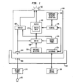
- Fig. 1 illustrates a component in an electrically powered device, where diagnostic data can be produced at the component or received from a device control, according to the invention.
- the component 100 is removably received in a slot 160 in a chassis of an electrically powered device, or otherwise installed in the device.
- the component 100 is removable from the electrically powered device typically for at least one of servicing and replacement, although it is not necessary for the component to be removable. While one component is discussed, note that a preferred embodiment of the invention may be used with any number of components in a device.
- one diagnostic indicator may be associated with multiple related components, and more than one indicator may be associated with one component.
- the component 100 includes a diagnostic indicator 105 such as an LED light, although other lights as well as audible indicators such as buzzers may be used as well.
- the diagnostic indicator 105 can be provided on a housing of the component, for instance, such as on a location on the housing that assists a user in locating the component within the electrically powered device.
- the indicator 105 may be located on the component 100 so that it is visible when an access door of the device or a higher-level assembly is opened.
- a driver circuit 110 may be used to drive the indicator.
- the driver 110 may be an LED driver circuit.
- the indicator 105 may be driven to provide a series of flashes for example.
- the driver circuit 110 may not be needed depending on the type of indicator used and the manner in which it is controlled. For example, when it is desired for the LED to appear to be illuminated, an LED driver circuit uses a series of high-frequency, short duration pulses to trick the eye into thinking it sees a continuous light, while avoiding overheating and burnout of the LED.
- other types of lights such as incandescent bulbs can withstand long periods of relatively high currents, in which case a driving circuit may not be needed. For example, it may be sufficient to connect a steady power supply to the light to indicate that servicing is needed.
- a data storage device 115 is used for storing data for identifying the diagnostic status that is to be indicated by the diagnostic indicator 105.
- the driver 110 associated with the data storage device 115 thus drives the diagnostic indicator 105 according to the data.
- Any type of data storage device may be used.
- the data storage device 115 may include a latch, or a volatile memory such as RAM.
- the data storage device 115 may store data as simple as one bit indicating whether the indicator should be powered or not. Or, the stored data may indicate a control mode to be used by the driver 110 in driving the indicator 105. For example, two bits of data may be stored to identify up to four different control modes.
- the data storage device 115 requires power to maintain the data - if power is lost, the data is lost as well.
- the data for controlling the indicator 105 may be provided locally, such as from a control 125 of the component 100, when the component 100 has on-board diagnostics, or the data may be received from outside the component 100.
- a higher-level device control 180 may provide data to the component 100 via the component interface 150.
- a central control in the device that controls the state of the diagnostic indicators in one or more components is useful in setting maintenance conditions for order-dependent tasks.
- Sensors and/or actuators 120 of the component 100 provide signals to the control 125 and/or the device control 180 for processing by diagnostic logic to determine a diagnostic status of the component.
- the diagnostic logic may detect that an actuator is not working properly, in which case appropriate status data is provided to the data storage device 115 for use in driving the indicator 105.
- the control 125 and/or the device control 180 may have associated program storage devices such as memories for storing software instructions that are executed to achieve the desired functionality.
- a preferred embodiment of the invention may use one or more program storage devices tangibly embodying or otherwise storing a program of instructions, e.g., software or microcode, executable by a machine, e.g., one or more processors, to achieve all or part of the functionality described herein.
- a program of instructions e.g., software or microcode
- a backup power device 135 is a self-contained power source such as a battery.
- the component 100 receives power from a primary power source 170 of the device.
- a jack 140 on the component may connect to a socket 165 in the slot 160 of the electrically powered device.
- a switch 130 connects either the jack 140 or the backup power source 135 to the driver 110 and data storage device 115, and optionally to other circuits in the component 100 as well, such as the control 125.
- the indicator 105 is also powered, directly or indirectly, by the power source selected by the switch 130.
- a further switch 132 may be provided to separately route the primary or backup power to the diagnostic indicator 105, as discussed further below. The functionality of the switches 130 and 132 may be combined as well into one device.
- the switch 130 may be configured to select the jack 140 when the primary power is present via the jack 140.
- the switch 130 may include circuitry having diodes, transistors or other elements that are activated based on whether the primary power supply is present on the line from the jack 140.
- the switch 130 may use a comparing circuit to compare the power level on the jack 140 to the power level of the backup power source 135, and select the backup power source when the primary power level is less than the back power level.
- the switch 130 may assess an absolute level of the power level on the jack 140, and select the backup power source 135 if the level is below a predetermined level.
- the primary power at the jack 140 may be unavailable to the component 100 for various reasons.
- the component 100 may be removed from the slot 160, in which case the jack 140 is disconnected from the socket 165.
- the primary power source 170 may be shut down to the entire device for safety reasons by the technician.
- the component 100 is provided in a slot in a higher-level assembly, and the higher level assembly is connected to the primary power source 170 such as via a jack and socket. The primary power source is then unavailable to the higher-level assembly and the component when the user removes the higher-level assembly from the electrically powered device to access the component 100.
- the switch 130 may be responsive to a presence detector 145, which indicates whether the component 100 is installed in the electrically powered device, such as in the slot 160, or the component 100 has been removed from the electrically powered device.
- the presence detector 145 may use an electrical contact that is connected to ground via the slot 160 when the component 100 is installed, or a mechanical plunger switch or other switch that is physically actuated when the component 100 is installed in the slot 160, thereby opening or closing an electrical path that is detected by the switch 130.
- the switch 130 may be responsive to the presence detector 145 in different ways.
- the switch 130 may connect the backup power source 135 to the indicator 105, driver 110 and data storage device 115 when the presence detector 145 indicates the component has been removed from the slot 160 and therefore has lost the primary power source.
- the switch 132 may delay connecting the backup power source 135 to the diagnostic indicator 105 until the presence detector 145 indicates the component has been removed from the slot 160, for example, by the technician.
- the primary power source 170 may be powered by AC power, such as from a plug 175 to a wall outlet or to a higher voltage power supply.
- the primary power source 170 steps down the voltage and provides it to the various components within the device at a desired level.
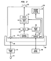
- Fig. 2 illustrates a component in an electrically powered device, where diagnostic data is received from a device control, according to the invention.
- the component 200 is analogous to the component 100 of Fig. 1 , but the local control 125 is not used. An on-board diagnostic capability is therefore not provided for the component 200, and all diagnostic processing is carried out by the device control 180, which provides the status data for controlling the indicator 105 directly to the data storage device 115 via the component's interface 150.
- the component 200 may be a modular power supply that has replaceable parts but which does not have a facility to diagnose failures at the module level.
- the device control 180 which is the main control of the device, runs the diagnostics, and in the event of a failure, sets the state of the diagnostic indicator 105.
- the device control 180 could set or clear the latch of the status data in the data storage device 115.
- the device control 180 could also oversee the non-diagnostic functions of the component 200.
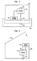
- Fig. 3 illustrates a component in an electrically powered device, where diagnostic data is produced at the component, according to the invention.
- the component 300 is analogous to the component 100 of Fig. 1 , but there is no interface 150 to the higher-level device control 180.
- the control 125 provides the on-board diagnostic capability, responsive to signals from the component sensors and/or actuators 120, to provide the status data for controlling the indicator 105 directly to the data storage device 115.
- Fig. 4 illustrates a component in an electrically powered device, where the component 410 with its diagnostic indicator 105 is located or enclosed within a higher-level assembly 400.
- the higher-level assembly 400 includes a presence detector 430 for detecting when it is removed from a slot 460 in a chassis of the electrically powered device, according to the invention.
- a jack 420 connects to a socket 465 in the slot 460 when the higher-level assembly 400 is installed in the slot 460, to receive the primary power from the electrically powered device.
- the primary power is connected via the jack 420 to the component 410.
- the presence detector 430 may function similarly to the presence detector 145 of Fig. 1 .
- switch 130 within the component 410 may connect the backup power source to the indicator 105, data storage device and driver when the presence detector 435 indicates the higher-level assembly 400 has been removed from the slot 460 and therefore has lost the primary power source.
- the switch 132 ( Fig. 1 ) may delay connecting the backup power source 135 to the indicator 105, as discussed further below, until the presence detector 430 indicates the component 410 has been removed from the slot 460, for example, by the technician.
- Fig. 5 illustrates the component 410 with its diagnostic indicator 105 in a higher-level assembly 500 in an electrically powered device, where the higher-level assembly 500 includes an access detector 510 for detecting when the higher-level assembly 500 has been opened to access the component 410, according to the invention.
- the higher-level assembly 500 includes an example access panel, lid or door 505 which the technician opens to access the component 410.
- the technician cannot view the indicator 105, when the indicator is a light, because it is covered by the door 505. Accordingly, it is not necessary to provide power to the indicator 415 until the access detector 510 detects that the higher-level assembly 500 has been opened.
- the access detector 510 may use a switch, for instance, that closes or opens a circuit when the door 505 is opened.
- the component 410 may use the switch 132 of Fig. 1 to separately power the diagnostic indicator 105.
- the switch 132 is responsive to the access detector 510 for connecting the backup power source 135 to power the diagnostic indicator. This approach reduces the drain on the backup power source because it avoids powering the indicator 105 unnecessarily.
- the backup power should be provided to the data storage device 115 as soon as the primary power source is removed to maintain the status data stored thereat.
- Fig. 6 illustrates multiple components and assemblies in a device, according to the invention.
- an electrically powered device such as a storage controller or other type of device includes its components in different sub-assemblies such as cabinets and the like that must be removed, opened and/or disassembled to some extent to access the components.
- the example device 600 includes a chassis 605 with a number of components installed therein.
- Components D1 (610) and D2 (670) are higher-level assemblies, while components C1 (620), A1 (630), B1 (640), B2 (650) and A2 (660) are individual components.
- Fig. 7 illustrates the sub-assembly component D2 (670) which has been removed from the chassis 605 by the technician.
- Fig. 8 illustrates an exploded view of the component D2 (670), showing its walls 671, 672, 673 and 674.
- Sub-components D2-0 (800) and D2-1 (810) are provided within the component D2 (670).
- the component D2 (670) is analogous to the higher-level assembly 500 of Fig.
- the access detector 510 may be used to avoid powering the diagnostic indicator with backup power until the component D2 (670) has been opened by the technician, thereby exposing the diagnostic indicator or indicators of the component or components within, e.g., components D2-0 (800) and D2-1 (810), which are analogous to component 410 in Fig. 5 .
- This approach reduces unnecessary use of the backup power, thereby extending its life.
Abstract
Description
- The invention relates generally to the field of service indicators such as diagnostic LEDs that are used to display information regarding a component of an electrically powered device such as a computer storage system, photocopier or the like, and, more specifically, to a way of providing backup power so that the service indicator continues to be active even when power is removed from the component.
- Various electrically powered devices such as computer systems, storage controllers, photocopiers and many others have a diagnostic functionality to indicate when servicing or replacement of their components is needed. Diagnostic control logic may process signals from sensors and actuators of the components to determine when a component is not performing properly or otherwise requires servicing, for instance. The components may have diagnostic indicators, e.g., service aid indicators, such as LED lights, that are illuminated to convey specified information. In a simple case, the light is illuminated when the component requires attention. In other cases, a series of flashes identifies the type of attention that is needed. However, for devices that have packaging concepts that require component assemblies to be removed from a chassis and therefore an associated electrical power source, the use of the diagnostic indicators to direct maintenance actions is compromised. Typically, the electrical power at the device is disconnected from the component, e.g., when the component is removed from the device, when a component is a subassembly located within a higher level assembly that must be removed from a chassis and disassembled, or when the technician switches off the power to the component for safety reasons, e.g., to avoid being shocked while working on the component.
- For example, during field maintenance of such devices, a directed service action is typically performed, where the device has identified and isolated a failure to a component within a subassembly that cannot be seen by the technician while the subassembly is installed within the higher order assembly. The service action may include servicing, including repair or cleaning, or replacement of a component, for instance. The technician may therefore require access to components internal to a sub-assembly to continue the maintenance activity. For instance, when a memory module is being serviced within a computer chassis, a common practice is for the technician to remove power to the computer chassis prior to disassembly. Once power has been removed from the chassis, service/diagnostic indicators that are powered from the chassis power source no longer have power. Once the chassis is opened, the technician wants to identify which component is being identified, by its diagnostic indicator, for servicing or replacement.
- In such situations, when the diagnostic indicator is no longer powered, it cannot aid the technician at a time when it is most needed.
- A related situation during certain manufacturing processes is known from, for example, United States Patent No.
6, 114,866 , which discloses indicator flags on a semiconductor test board that indicate failures during test and that persist after the test board has been removed from the burin-in oven. - In a first aspect, the present invention provides a component in an electrically powered device for performing a function of the electrically powered device, comprising: a diagnostic indicator for indicating a diagnostic status of the component; wherein the diagnostic indicator receives power from a primary power source that is associated with the electrically powered device when the primary power source is available to the component; a self-contained power source; and at least one switch for connecting the self-contained power source to power the diagnostic indicator when the primary power source is unavailable to the component.
- The component preferably further comprises: a housing for holding the self-contained power source and the at least one switch; wherein the diagnostic indicator is provided on the housing. Preferably, the primary power source is available to the component when the component is installed in the electrically powered device; and the primary power source is unavailable to the component when the component is removed from the electrically powered device.
- Preferably, the diagnostic indicator comprises a light.
- The component may further comprise: a presence detector that indicates when the component is installed in the electrically powered device, in which case the primary power source is available to the component, and when the component has been removed from the electrically powered device, in which case the primary power source is unavailable to the component; wherein the at least one switch is responsive to the presence detector.
- Preferably, the self-contained power source comprises a battery. Preferably, the component is removable from the electrically powered device for at least one of servicing and replacement.
- Preferably, the primary power source is unavailable to the component when a user disconnects the primary power source from the component as a safety precaution when servicing or replacing the component.
- Preferably, the primary power source is unavailable to the component when a user removes a higher-level assembly, in which the component is provided, from the electrically powered device, to access the component, thereby disconnecting the component from the primary power source.
- The component may further comprise: a presence detector that indicates when the higher-level assembly is installed in the electrically powered device, in which case the primary power source is available to the component, and when the higher-level assembly has been removed from the electrically powered device, in which case the primary power source is unavailable to the component; wherein the at least one switch is responsive to the presence detector.
- The component may further comprise: an access detector that indicates when the higher-level assembly has been opened to access the component; wherein the at least one switch is responsive to the access detector.
- The component may further comprise: a data storage device for storing data for identifying the diagnostic status that is to be indicated by the diagnostic indicator.
- The component may further comprise: a driver associated with the data storage device for driving the diagnostic indicator according to the data.
- Preferably, the data storage device latches the data when the self-contained power source is connected to power the data storage device.
- The component may further comprise: a control for providing the data.
- The component may further comprise: an interface for receiving the data from a control of the electrically powered device.
- There is further preferably provided a component in an electrically powered device for performing a function of the electrically powered device, comprising: means for indicating a diagnostic status of the component; wherein the means for indicating receives power from a primary power source that is associated with the electrically powered device when the primary power source is available to the component; a self-contained power source; and means for connecting the self-contained power source to power the diagnostic indicator when the primary power source is unavailable to the component.
- In a second aspect, the present invention provides an apparatus for use in a component in an electrically powered device, comprising: a self-contained power source; and at least one switch for connecting the self-contained power source to power a diagnostic indicator of the component when a primary power source that is associated with the electrically powered device is unavailable to the component; wherein diagnostic indicator indicates a diagnostic status of the component.
- It is preferred to provide apparatus for use in a component in an electrically powered device, comprising: a self-contained power source; and at least one switch for connecting the self-contained power source to power a data storage device of the component when a primary power source that is associated with the electrically powered device is unavailable to the component; wherein the data storage device stores data for identifying a diagnostic status that is to be indicated by a diagnostic indicator of the component.
- There may be provided a component in an electrically powered device for performing a function of the electrically powered device, comprising: a diagnostic indicator for indicating a diagnostic status of the component; a data storage device for storing data for identifying the diagnostic status that is to be indicated by the diagnostic indicator; wherein the data storage device receives power from a primary power source that is associated with the electrically powered device when the primary power source is available to the component; a self-contained power source; and at least one switch for connecting the self-contained power source to power the data storage device to maintain the data stored thereat when the primary power source is unavailable to the component.
The component of claim 20, further comprising: a housing for holding the self-contained power source and the at least one switch; wherein the diagnostic indicator is provided on the housing. - Preferably, the diagnostic indicator receives power from the primary power source when the primary power source is available to the component; and the at least one switch connects the self-contained power source to power the diagnostic indicator when the primary power source is unavailable to the component.
- Preferably, the primary power source is available to the component when the component is installed in the electrically powered device; and the primary power source is unavailable to the component when the component is removed from the electrically powered device.
- Preferably, the diagnostic indicator comprises a light.
- The component may further comprise: a presence detector that indicates when the component is installed in the electrically powered device, in which case the primary power source is available to the component, and when the component has been removed from the electrically powered device, in which case the primary power source is unavailable to the component; wherein the at least one switch is responsive to the presence detector.
- Preferably, the self-contained power source comprises a battery.
- Preferably, the component is removable from the electrically powered device for at least one of servicing and replacement.
- Preferably, the primary power source is unavailable to the component when a user disconnects the primary power source from the component as a safety precaution when servicing or replacing the component.
- Preferably, the primary power source is unavailable to the component when a user removes a higher-level assembly, in which the component is provided, from the electrically powered device, to access the component, thereby disconnecting the component from the primary power source.
- The component may further comprise: a presence detector that indicates when the higher-level assembly is installed in the electrically powered device, in which case the primary power source is available to the component, and when the higher-level assembly has been removed from the electrically powered device, in which case the primary power source is unavailable to the component; wherein the at least one switch is responsive to the presence detector.
- The component may further comprise: an access detector that indicates when the higher-level assembly has been opened to access the component; and a further switch, responsive to the access detector, for connecting the self-contained power source to power the diagnostic indicator.
- The component may further comprise: a driver associated with the data storage device for driving the diagnostic indicator according to the data.
- Preferably, the data storage device latches the data when the self-contained power source is connected to power the data storage device.
- The component may further comprise: a control for providing the data.
- The component may further comprise an interface for receiving the data from a control of the electrically powered device.
- There is thus preferably provided a component in an electrically powered device for performing a function of the electrically powered device, comprising: means for indicating a diagnostic status of the component; means for storing data for identifying the diagnostic status that is to be indicated by the means for indicating; wherein the means for storing data receives power from a primary power source that is associated with the electrically powered device when the primary power source is available to the component; a self-contained power source; and means for connecting the self-contained power source to power the data storage device to maintain the data stored thereat when the primary power source is unavailable to the component.
- There is further preferably provided a method for powering a component having a diagnostic indicator, where the component is provided in an electrically powered device for performing a function of the electrically powered device, comprising: receiving power, at the component, from a primary power source that is associated with the electrically powered device when the primary power source is available to the component; connecting the primary power source to power the diagnostic indicator when the primary power source is available to the component; and connecting a self-contained power source of the component to power the diagnostic indicator when the primary power source is unavailable to the component.
- There is further preferably provided a method for powering a component having a diagnostic indicator and a data storage device, where the component is provided in an electrically powered device for performing a function of the electrically powered device, comprising: storing, at the data storage device, data for identifying a diagnostic status of the component that is to be indicated by the diagnostic indicator; receiving power, at the component, from a primary power source that is associated with the electrically powered device when the primary power source is available to the component; connecting the primary power source to power the data storage device when the primary power source is available to the component; and connecting a self-contained power source of the component to power the data storage device when the primary power source is unavailable to the component.
- The present invention may be implemented in a program storage device tangibly embodying a program of instructions executable by a machine to perform a method for powering a component having a diagnostic indicator, wherein the component is provided in an electrically powered device for performing a function of the electrically powered device, and wherein the component receives power from a primary power source that is associated with the electrically powered device when the primary power source is available to the component, the method comprising: connecting the primary power source to power the diagnostic indicator when the primary power source is available to the component; and connecting a self-contained power source of the component to power the diagnostic indicator when the primary power source is unavailable to the component.
- The present invention may be implemented in a program storage device tangibly embodying a program of instructions executable by a machine to perform a method for powering a component having a diagnostic indicator and a data storage device, wherein the component is provided in an electrically powered device for performing a function of the electrically powered device, and wherein the component receives power from a primary power source that is associated with the electrically powered device when the primary power source is available to the component, the method comprising: storing, at the data storage device, data for identifying a diagnostic status of the component that is to be indicated by the diagnostic indicator; and connecting the primary power source to power the data storage device when the primary power source is available to the component; and connecting a self-contained power source of the component to power the data storage device when the primary power source is unavailable to the component.
- The present invention thus addresses the above and other issues by providing a technique that allows a diagnostic indicator to be powered from an alternative, independent power source when normal system power is removed from a component, thereby preserving the use of the diagnostic indicator to complete a maintenance task.
- Specifically, dual power sources are provided for the diagnostic indicator. The primary source is the normal system power of the device in which the component is installed. Typically, this power source is based on AC power from an electrical outlet. The AC input power source can be conditioned to become DC power used by the internal circuitry and control functions. An alternate source is a self-contained power source such as a battery that can be located within or on the component itself. By using the device's power source as the primary power source, the life of the alternate power source is preserved. Moreover, when the component needs to be removed from the device and, therefore, from the primary power source, the state of the diagnostic indicator is latched and shifted to the alternate power source, thereby preserving the functionality of the diagnostic indicator.
- In one aspect of the invention, a component in an electrically powered device for performing a function of the electrically powered device includes a diagnostic indicator for indicating a diagnostic status of the component. The diagnostic indicator receives power from a primary power source that is associated with the electrically powered device when the primary power source is available to the component. The component also includes a self-contained power source, and at least one switch for connecting the self-contained power source to power the diagnostic indicator when the primary power source is unavailable to the component.
- In a further aspect of the invention, a component of the above-mentioned type includes means for indicating a diagnostic status of the component, wherein the means for indicating receives power from a primary power source that is associated with the electrically powered device when the primary power source is available to the component, a self-contained power source, and means for connecting the self-contained power source to power the diagnostic indicator when the primary power source is unavailable to the component.
- In a further aspect of the invention, an apparatus for use in a component in an electrically powered device includes a self-contained power source, and at least one switch for connecting the self-contained power source to power a diagnostic indicator of the component when a primary power source that is associated with the electrically powered device is unavailable to the component. The diagnostic indicator indicates a diagnostic status of the component.
In a further aspect of the invention, an apparatus for use in a component in an electrically powered device includes a self-contained power source, and at least one switch for connecting the self-contained power source to power a data storage device of the component when a primary power source that is associated with the electrically powered device is unavailable to the component. The data storage device stores data for identifying a diagnostic status that is to be indicated by a diagnostic indicator of the component. - In a further aspect of the invention, a component of the above-mentioned type includes a data storage device for storing data for identifying the diagnostic status that is to be indicated by the diagnostic indicator, wherein the data storage device receives power from a primary power source that is associated with the electrically powered device when the primary power source is available to the component, a self-contained power source, and at least one switch for connecting the self-contained power source to power the data storage device to maintain the data stored thereat when the primary power source is unavailable to the component.
- In a further aspect of the invention, a component in an electrically powered device for performing a function of the electrically powered device includes means for indicating a diagnostic status of the component, and means for storing data for identifying the diagnostic status that is to be indicated by the means for indicating. The means for storing data receives power from a primary power source that is associated with the electrically powered device when the primary power source is available to the component. The component further includes a self-contained power source, and means for connecting the self-contained power source to power the data storage device to maintain the data stored thereat when the primary power source is unavailable to the component.
- In a further aspect of the invention, a method for powering a component having a diagnostic indicator, where the component is provided in an electrically powered device for performing a function of the electrically powered device, includes: (a) receiving power, at the component, from a primary power source that is associated with the electrically powered device when the primary power source is available to the component, (b) connecting the primary power source to power the diagnostic indicator when the primary power source is available to the component, and (c) connecting a self-contained power source of the component to power the diagnostic indicator when the primary power source is unavailable to the component.
- In a further aspect of the invention, a method for powering a component having a diagnostic indicator and a data storage device, where the component is provided in an electrically powered device for performing a function of the electrically powered device, includes: (a) storing, at the data storage device, data for identifying a diagnostic status of the component that is to be indicated by the diagnostic indicator, (b) receiving power, at the component, from a primary power source that is associated with the electrically powered device when the primary power source is available to the component, (c) connecting the primary power source to power the data storage device when the primary power source is available to the component, and (d) connecting a self-contained power source of the component to power the data storage device when the primary power source is unavailable to the component.
Corresponding program storage devices may also be provided. - A preferred embodiment of the present invention will now be described, by way of example only, with reference to the appended figures, wherein:
-
Fig. 1 illustrates a component in an electrically powered device, where diagnostic data can be produced at the component or received from a device control, according to a preferred embodiment of the invention; -
Fig. 2 illustrates a component in an electrically powered device, where diagnostic data is received from a device control, according to a preferred embodiment of the invention; -
Fig. 3 illustrates a component in an electrically powered device, where diagnostic data is produced at the component, according to a preferred embodiment of the invention; -
Fig. 4 illustrates a component in an electrically powered device, where the component includes a presence detector for detecting when the component is removed from a slot in a chassis of the electrically powered device, according to a preferred embodiment of the invention; -
Fig. 5 illustrates a component in a higher-level assembly in an electrically powered device, where the higher-level assembly includes an access detector for detecting when the higher-level assembly has been opened to access the component, according to a preferred embodiment of the invention; -
Fig. 6 illustrates multiple components and assemblies in a device, according to a preferred embodiment of the invention; -
Fig. 7 illustrates a sub-assembly in a device that is opened to access a component, according to a preferred embodiment of the invention; and -
Fig. 8 illustrates components provided within a sub-assembly, according to a preferred embodiment of the invention. - In a system that uses diagnostic indicators to assist in maintenance identification of components, a preferred embodiment of the invention provides an alternate power source and a means of latching the indicator state that is powered from the alternate power source. When a maintenance activity that will remove the normal power source from the diagnostic indicator is required, the system places the indicator into a state that is required for the service activity and transfers the latched state and power source for the indicator to the alternate source. This can be done either manually by the technician, such as by moving a switch, or automatically, such as upon removal of normal power to the indicator. The state of the indicators is maintained and the service activity can continue to exploit the diagnostic indicators with the higher-level assembly removed from the enclosure/chassis.
- As indicated, various electrically powered devices have packaging concepts that require component assemblies to be removed from a chassis. For example, a high availability storage controller such as IBM's TotalStorage SAN Volume Controller has many components with diagnostic functionality. Such devices include a number of components that are subassemblies located within a higher-level assembly that is removed from a chassis. Furthermore, high availability RAID storage systems will have "dual active" controllers, with potentially many independent subsystems within the higher-level system or enclosure chassis. For example, Controller Node Assemblies include Memory, Processors, Plug-In Adapters (e.g., PCI Cards), and Voltage Regulator Modules. A Power Supply includes Power Control Modules and Voltage Regulator Modules. Uninterruptible Power Supplies/Battery Units include a Battery Pack Assembly and Controller Logic Module. Other example components include Operator/Control Panels, Hard Disk Drives, and Fans/Blowers. Various other components in other types of electrically powered devices, including photocopiers, printers and the like, will be apparent to those skilled in the art. Generally, each component performs some function of the device.
- A rudimentary diagnostic indicator provides an indication of a component that has failed within a device and therefore requires service or replacement. An LED placed in proximity to the component requiring service is an example. The concept can be extended to lock/latch in some diagnostic error information in a subassembly, e.g., using seven-segment LED displays, if desired. Moreover, as mentioned, sequences of flashes may convey specific diagnostic information as well.
-
Fig. 1 illustrates a component in an electrically powered device, where diagnostic data can be produced at the component or received from a device control, according to the invention. Thecomponent 100 is removably received in aslot 160 in a chassis of an electrically powered device, or otherwise installed in the device. Thecomponent 100 is removable from the electrically powered device typically for at least one of servicing and replacement, although it is not necessary for the component to be removable. While one component is discussed, note that a preferred embodiment of the invention may be used with any number of components in a device. Moreover, one diagnostic indicator may be associated with multiple related components, and more than one indicator may be associated with one component. Thecomponent 100 includes adiagnostic indicator 105 such as an LED light, although other lights as well as audible indicators such as buzzers may be used as well. Thediagnostic indicator 105 can be provided on a housing of the component, for instance, such as on a location on the housing that assists a user in locating the component within the electrically powered device. For example, theindicator 105 may be located on thecomponent 100 so that it is visible when an access door of the device or a higher-level assembly is opened. - A
driver circuit 110 may be used to drive the indicator. For example, when the indicator is an LED, thedriver 110 may be an LED driver circuit. Theindicator 105 may be driven to provide a series of flashes for example. Thedriver circuit 110 may not be needed depending on the type of indicator used and the manner in which it is controlled. For example, when it is desired for the LED to appear to be illuminated, an LED driver circuit uses a series of high-frequency, short duration pulses to trick the eye into thinking it sees a continuous light, while avoiding overheating and burnout of the LED. However, other types of lights such as incandescent bulbs can withstand long periods of relatively high currents, in which case a driving circuit may not be needed. For example, it may be sufficient to connect a steady power supply to the light to indicate that servicing is needed. - A
data storage device 115 is used for storing data for identifying the diagnostic status that is to be indicated by thediagnostic indicator 105. Thedriver 110 associated with thedata storage device 115 thus drives thediagnostic indicator 105 according to the data. Any type of data storage device may be used. For example, thedata storage device 115 may include a latch, or a volatile memory such as RAM. Thedata storage device 115 may store data as simple as one bit indicating whether the indicator should be powered or not. Or, the stored data may indicate a control mode to be used by thedriver 110 in driving theindicator 105. For example, two bits of data may be stored to identify up to four different control modes. Typically, thedata storage device 115 requires power to maintain the data - if power is lost, the data is lost as well. - The data for controlling the
indicator 105 may be provided locally, such as from acontrol 125 of thecomponent 100, when thecomponent 100 has on-board diagnostics, or the data may be received from outside thecomponent 100. For example, a higher-level device control 180 may provide data to thecomponent 100 via thecomponent interface 150. A central control in the device that controls the state of the diagnostic indicators in one or more components is useful in setting maintenance conditions for order-dependent tasks. Sensors and/oractuators 120 of thecomponent 100 provide signals to thecontrol 125 and/or thedevice control 180 for processing by diagnostic logic to determine a diagnostic status of the component. For example, the diagnostic logic may detect that an actuator is not working properly, in which case appropriate status data is provided to thedata storage device 115 for use in driving theindicator 105. Thecontrol 125 and/or thedevice control 180 may have associated program storage devices such as memories for storing software instructions that are executed to achieve the desired functionality. - Generally, a preferred embodiment of the invention may use one or more program storage devices tangibly embodying or otherwise storing a program of instructions, e.g., software or microcode, executable by a machine, e.g., one or more processors, to achieve all or part of the functionality described herein.
- A
backup power device 135 is a self-contained power source such as a battery. In normal operation, when the electrically powered device is not being serviced, thecomponent 100 receives power from aprimary power source 170 of the device. For example, ajack 140 on the component may connect to asocket 165 in theslot 160 of the electrically powered device. Aswitch 130 connects either thejack 140 or thebackup power source 135 to thedriver 110 anddata storage device 115, and optionally to other circuits in thecomponent 100 as well, such as thecontrol 125. Theindicator 105 is also powered, directly or indirectly, by the power source selected by theswitch 130. Afurther switch 132 may be provided to separately route the primary or backup power to thediagnostic indicator 105, as discussed further below. The functionality of theswitches - The
switch 130 may be configured to select thejack 140 when the primary power is present via thejack 140. For example, theswitch 130 may include circuitry having diodes, transistors or other elements that are activated based on whether the primary power supply is present on the line from thejack 140. Various approaches apparent to those skilled in the art may be used. For example, theswitch 130 may use a comparing circuit to compare the power level on thejack 140 to the power level of thebackup power source 135, and select the backup power source when the primary power level is less than the back power level. Or, theswitch 130 may assess an absolute level of the power level on thejack 140, and select thebackup power source 135 if the level is below a predetermined level. - The primary power at the
jack 140 may be unavailable to thecomponent 100 for various reasons. For example, thecomponent 100 may be removed from theslot 160, in which case thejack 140 is disconnected from thesocket 165. Moreover, even when thecomponent 100 is installed in theslot 160, theprimary power source 170 may be shut down to the entire device for safety reasons by the technician. In another possibility, thecomponent 100 is provided in a slot in a higher-level assembly, and the higher level assembly is connected to theprimary power source 170 such as via a jack and socket. The primary power source is then unavailable to the higher-level assembly and the component when the user removes the higher-level assembly from the electrically powered device to access thecomponent 100. - Furthermore, the
switch 130 may be responsive to apresence detector 145, which indicates whether thecomponent 100 is installed in the electrically powered device, such as in theslot 160, or thecomponent 100 has been removed from the electrically powered device. For example, thepresence detector 145 may use an electrical contact that is connected to ground via theslot 160 when thecomponent 100 is installed, or a mechanical plunger switch or other switch that is physically actuated when thecomponent 100 is installed in theslot 160, thereby opening or closing an electrical path that is detected by theswitch 130. Theswitch 130 may be responsive to thepresence detector 145 in different ways. For example, theswitch 130 may connect thebackup power source 135 to theindicator 105,driver 110 anddata storage device 115 when thepresence detector 145 indicates the component has been removed from theslot 160 and therefore has lost the primary power source. Or, theswitch 132 may delay connecting thebackup power source 135 to thediagnostic indicator 105 until thepresence detector 145 indicates the component has been removed from theslot 160, for example, by the technician. - The
primary power source 170 may be powered by AC power, such as from aplug 175 to a wall outlet or to a higher voltage power supply. Theprimary power source 170 steps down the voltage and provides it to the various components within the device at a desired level. - Note that the functionality discussed herein may be achieved by any configuration and arrangement of elements. The configuration and arrangement shown in
Fig. 1 and elsewhere is meant to be an example only. For example, the functionality of different elements may be combined into one element, or the functionality of one elements as described may be spread out among multiple elements. -
Fig. 2 illustrates a component in an electrically powered device, where diagnostic data is received from a device control, according to the invention. Thecomponent 200 is analogous to thecomponent 100 ofFig. 1 , but thelocal control 125 is not used. An on-board diagnostic capability is therefore not provided for thecomponent 200, and all diagnostic processing is carried out by thedevice control 180, which provides the status data for controlling theindicator 105 directly to thedata storage device 115 via the component'sinterface 150. For example, thecomponent 200 may be a modular power supply that has replaceable parts but which does not have a facility to diagnose failures at the module level. In this case, thedevice control 180, which is the main control of the device, runs the diagnostics, and in the event of a failure, sets the state of thediagnostic indicator 105. Thedevice control 180 could set or clear the latch of the status data in thedata storage device 115.
Thedevice control 180 could also oversee the non-diagnostic functions of thecomponent 200. -
Fig. 3 illustrates a component in an electrically powered device, where diagnostic data is produced at the component, according to the invention. Thecomponent 300 is analogous to thecomponent 100 ofFig. 1 , but there is nointerface 150 to the higher-level device control 180. In this case, thecontrol 125 provides the on-board diagnostic capability, responsive to signals from the component sensors and/oractuators 120, to provide the status data for controlling theindicator 105 directly to thedata storage device 115. -
Fig. 4 illustrates a component in an electrically powered device, where thecomponent 410 with itsdiagnostic indicator 105 is located or enclosed within a higher-level assembly 400. The higher-level assembly 400 includes apresence detector 430 for detecting when it is removed from aslot 460 in a chassis of the electrically powered device, according to the invention. Ajack 420 connects to asocket 465 in theslot 460 when the higher-level assembly 400 is installed in theslot 460, to receive the primary power from the electrically powered device. The primary power is connected via thejack 420 to thecomponent 410. Thepresence detector 430 may function similarly to thepresence detector 145 ofFig. 1 . For example, switch 130 within thecomponent 410 may connect the backup power source to theindicator 105, data storage device and driver when the presence detector 435 indicates the higher-level assembly 400 has been removed from theslot 460 and therefore has lost the primary power source. The switch 132 (Fig. 1 ) may delay connecting thebackup power source 135 to theindicator 105, as discussed further below, until thepresence detector 430 indicates thecomponent 410 has been removed from theslot 460, for example, by the technician. -
Fig. 5 illustrates thecomponent 410 with itsdiagnostic indicator 105 in a higher-level assembly 500 in an electrically powered device, where the higher-level assembly 500 includes anaccess detector 510 for detecting when the higher-level assembly 500 has been opened to access thecomponent 410, according to the invention. The higher-level assembly 500 includes an example access panel, lid ordoor 505 which the technician opens to access thecomponent 410. In this situation, the technician cannot view theindicator 105, when the indicator is a light, because it is covered by thedoor 505. Accordingly, it is not necessary to provide power to the indicator 415 until theaccess detector 510 detects that the higher-level assembly 500 has been opened. Theaccess detector 510 may use a switch, for instance, that closes or opens a circuit when thedoor 505 is opened. Thecomponent 410 may use theswitch 132 ofFig. 1 to separately power thediagnostic indicator 105. In this case, theswitch 132 is responsive to theaccess detector 510 for connecting thebackup power source 135 to power the diagnostic indicator. This approach reduces the drain on the backup power source because it avoids powering theindicator 105 unnecessarily. However, note that the backup power should be provided to thedata storage device 115 as soon as the primary power source is removed to maintain the status data stored thereat.
Fig. 6 illustrates multiple components and assemblies in a device, according to the invention. Typically, an electrically powered device such as a storage controller or other type of device includes its components in different sub-assemblies such as cabinets and the like that must be removed, opened and/or disassembled to some extent to access the components. Theexample device 600 includes achassis 605 with a number of components installed therein. Components D1 (610) and D2 (670) are higher-level assemblies, while components C1 (620), A1 (630), B1 (640), B2 (650) and A2 (660) are individual components.Fig. 7 illustrates the sub-assembly component D2 (670) which has been removed from thechassis 605 by the technician. The technician may know, through experience or by following a trouble shooting routine, for instance, that a problem component is likely to be in a given sub-assembly by the nature of the malfunction of the device. An access panel ordoor 675 has been removed by the technician to gain access to the inside of the component D2 (670).Fig. 8 illustrates an exploded view of the component D2 (670), showing itswalls level assembly 500 ofFig. 5 , where theaccess detector 510 may be used to avoid powering the diagnostic indicator with backup power until the component D2 (670) has been opened by the technician, thereby exposing the diagnostic indicator or indicators of the component or components within, e.g., components D2-0 (800) and D2-1 (810), which are analogous tocomponent 410 inFig. 5 . This approach reduces unnecessary use of the backup power, thereby extending its life. - The preferred embodiment of the invention has been described herein with reference to particular exemplary embodiments. Certain alterations and modifications may be apparent to those skilled in the art, without departing from the scope of the invention. The exemplary embodiments are meant to be illustrative, not limiting of the scope of the invention, which is defined by the appended claims.
Claims (6)
- A component (100) installable in an electrically powered device for performing a function of the electrically powered device, comprising:a diagnostic indicator (105) for indicating a diagnostic status of the component (100);wherein the diagnostic indicator (105) receives power from a primary power source (170) that is associated with the electrically powered device when the primary power source (170) is available to the component (100);a self-contained power source (135);at least one switch (130) for connecting the self-contained power source (135) to power the diagnostic indicator (105) when the primary power source (170) is unavailable to the component (100), anda presence detector (145) for indicating when the component (100) is installed in the electrically powered device, in which case the primary power source (170) is available to the component (100), and when the component (100) has been removed from the electrically powered device, in which case the primary power source (170) is unavailable to the component (100);
characterised in that:the at least one switch (130) is responsive to the presence detector (145). - The component of claim 1, further comprising:a housing for holding the self-contained power source and the at least one switch;wherein the diagnostic indicator is provided on the housing.
- A higher-level assembly (400) installable in an electrically powered device and comprising a component, (410) wherein the component (410) is operable for performing a function of the electrically powered device, said higher-level assembly (400) comprising:a diagnostic indicator (105) within said component (410) for indicating a diagnostic status of the component (410);wherein the diagnostic indicator (105) receives power from a primary power source (170) that is associated with the electrically powered device when the primary power source (170) is available to the component (410);a self-contained power source (135) within said component (410);at least one switch (130) within said component (410) for connecting the self-contained power source (135) to power the diagnostic indicator (105) when the primary power source (170) is unavailable to the component (410), anda presence detector (430) for indicating when the higher-level assembly (400) is installed in the electrically powered device, in which case the primary power source (170) is available to the component (410) and when the higher-level assembly (400) has been removed from the electrically powered device, in which case the primary power source (170) is unavailable to the component (410) characterised in that:the at least one switch (130) is responsive to the presence detector (430).
- A method for powering a component (100) having a diagnostic indicator (105), where the component (100) is provided in an electrically powered device for performing a function of the electrically powered device, comprising:receiving power, at the component (100), from a primary power source (170) that is associated with the electrically powered device when the primary power source (170) is available to the component (100);connecting the primary power source (170) to power the diagnostic indicator (105) when the primary power source (170) is available to the component (100), connecting by means of a switch (130) a self-contained power source (135) of the component (100) to power the diagnostic indicator (105) when the primary power source (170) is unavailable to the component (100); andindicating by a presence detector (145) when the component (100) is installed in the electrically powered device, in which case the primary power source (170) is available to the component (100), and when the component (100) has been removed from the electrically powered device, in which case the primary power source (170) is unavailable to the component. (100), characterised in:responding by the at least one switch (130) to the presence detector (145).
- The method of claim 4, further comprising:providing a housing for holding the self-contained power source and the at least one switch;wherein the diagnostic indicator is provided on the housing.
- A computer program comprising computer program code to, when loaded into a computer system comprising componentry as recited in claim 1 or claim 2 and executed thereon, cause said computer system to execute the steps of a method as claimed in claim 4 or claim 5.
Applications Claiming Priority (2)
| Application Number | Priority Date | Filing Date | Title |
|---|---|---|---|
| US10/976,202 US7259665B2 (en) | 2004-10-27 | 2004-10-27 | Battery backed service indicator aids for field maintenance |
| PCT/EP2005/054843 WO2006045684A1 (en) | 2004-10-27 | 2005-09-27 | Battery backed service indicator aids for field maintenance |
Publications (2)
| Publication Number | Publication Date |
|---|---|
| EP1812862A1 EP1812862A1 (en) | 2007-08-01 |
| EP1812862B1 true EP1812862B1 (en) | 2012-08-22 |
Family
ID=35478779
Family Applications (1)
| Application Number | Title | Priority Date | Filing Date |
|---|---|---|---|
| EP05791998A Not-in-force EP1812862B1 (en) | 2004-10-27 | 2005-09-27 | Battery backed service indicator aids for field maintenance |
Country Status (7)
| Country | Link |
|---|---|
| US (2) | US7259665B2 (en) |
| EP (1) | EP1812862B1 (en) |
| JP (1) | JP4516989B2 (en) |
| KR (1) | KR100992028B1 (en) |
| CN (1) | CN100461129C (en) |
| CA (1) | CA2580470C (en) |
| WO (1) | WO2006045684A1 (en) |
Families Citing this family (7)
| Publication number | Priority date | Publication date | Assignee | Title |
|---|---|---|---|---|
| US8922058B2 (en) * | 2008-11-18 | 2014-12-30 | Ringdale, Inc. | LED lighting controller with cascading signaling |
| US8896460B2 (en) * | 2011-09-23 | 2014-11-25 | Osram Sylvania Inc. | Lighting control |
| CN102411532A (en) * | 2011-12-31 | 2012-04-11 | 曙光信息产业股份有限公司 | Computer failure reminding method and device, and computer |
| CN103207825A (en) * | 2012-01-13 | 2013-07-17 | 百度在线网络技术(北京)有限公司 | Method and device for managing faults of entire equipment cabinet |
| US10159163B2 (en) | 2014-09-10 | 2018-12-18 | Hewlett Packard Enterprise Development Lp | Indicate a functional status of corresponding electronic devices |
| CN107870846B (en) * | 2016-09-23 | 2021-04-02 | 伊姆西Ip控股有限责任公司 | Fault element indication method, device and system |
| US11223227B1 (en) * | 2019-07-03 | 2022-01-11 | Capsa Solutions Llc | Medical cart providing data continuity |
Family Cites Families (28)
| Publication number | Priority date | Publication date | Assignee | Title |
|---|---|---|---|---|
| US4168796A (en) | 1978-04-13 | 1979-09-25 | Ncr Corporation | Tester with driver/sensor circuit having programmable termination devices |
| US4196386A (en) | 1978-04-13 | 1980-04-01 | Ncr Corporation | Method and portable apparatus for testing digital printed circuit boards |
| US4194113A (en) | 1978-04-13 | 1980-03-18 | Ncr Corporation | Method and apparatus for isolating faults in a logic circuit |
| JPS634135U (en) * | 1986-06-23 | 1988-01-12 | ||
| JPS63156212A (en) * | 1986-12-19 | 1988-06-29 | Sanyo Electric Co Ltd | Power supply controller for computer |
| JPH04348413A (en) * | 1991-04-17 | 1992-12-03 | Kyocera Corp | Personal computer |
| JP3097065B2 (en) * | 1991-04-23 | 2000-10-10 | セイコーエプソン株式会社 | Information processing equipment |
| US5519832A (en) * | 1992-11-13 | 1996-05-21 | Digital Equipment Corporation | Method and apparatus for displaying module diagnostic results |
| US5673028A (en) | 1993-01-07 | 1997-09-30 | Levy; Henry A. | Electronic component failure indicator |
| US5574436A (en) * | 1993-07-21 | 1996-11-12 | Sisselman; Ronald | Smoke detector including an indicator for indicating a missing primary power source which is powered by a substantially nonremovable secondary power source |
| US5604708A (en) * | 1995-01-25 | 1997-02-18 | Dell Usa L.P. | Fail-safe system for preserving a backup battery |
| US5706239A (en) * | 1996-02-27 | 1998-01-06 | Centennial Technologies, Inc. | Rechargeable SRAM/flash PCMCIA card |
| JPH09248955A (en) * | 1996-03-14 | 1997-09-22 | Ricoh Co Ltd | Electronic apparatus having display |
| JP3505029B2 (en) * | 1996-03-21 | 2004-03-08 | 大日本スクリーン製造株式会社 | Power supply apparatus and substrate processing apparatus having the same |
| CA2206969C (en) * | 1997-06-04 | 2006-08-08 | Digital Security Controls Ltd. | Self diagnostic heat detector |
| JPH1183938A (en) | 1997-09-08 | 1999-03-26 | Mitsubishi Electric Corp | Test board for semiconductor device and evaluation and test method for semiconductor device using it |
| US6095851A (en) * | 1997-11-17 | 2000-08-01 | Xircom, Inc. | Status indicator for electronic device |
| US6433698B1 (en) | 1998-04-30 | 2002-08-13 | E.O. Schweitzer Mfg. Co. | Fault indicator providing light indication on fault detection |
| US6098131A (en) * | 1998-05-04 | 2000-08-01 | Nortel Networks Limited | Network apparatus with removable electronic module |
| US6535944B1 (en) * | 1999-03-30 | 2003-03-18 | International Business Machines Corporation | Hot plug control of MP based computer system |
| US6762930B2 (en) * | 2002-01-17 | 2004-07-13 | Hewlett-Packard Development Company, L.P. | Form factor card with status indicator |
| US6644556B2 (en) * | 2002-01-18 | 2003-11-11 | Hewlett-Packard Development Company, L.P. | Storage device including storage space indication |
| US6760672B2 (en) * | 2002-01-29 | 2004-07-06 | Rockwell Automation Technologies, Inc. | Automatic detection of battery-backed data integrity in volatile memory |
| ATE382895T1 (en) | 2002-04-03 | 2008-01-15 | Hewlett Packard Co | DATA PROCESSING DEVICE AND METHOD WITH CONDITION INDICATOR |
| US6867704B2 (en) * | 2003-02-28 | 2005-03-15 | Dell Products L.P. | Bi-color light source for indicating status of information handling system |
| US7084608B2 (en) * | 2003-07-22 | 2006-08-01 | Agere Systems Inc. | PCMCIA card with dedicated on-board battery |
| US7161485B2 (en) * | 2003-10-02 | 2007-01-09 | Emanuel Melman | Emergency vehicle transmitter and receiver alert system |
| US7161495B1 (en) * | 2004-04-30 | 2007-01-09 | Network Applicance, Inc. | Alert for indicating validity of removable memory media |
-
2004
- 2004-10-27 US US10/976,202 patent/US7259665B2/en not_active Expired - Fee Related
-
2005
- 2005-09-27 WO PCT/EP2005/054843 patent/WO2006045684A1/en active Application Filing
- 2005-09-27 CA CA2580470A patent/CA2580470C/en active Active
- 2005-09-27 KR KR1020077009549A patent/KR100992028B1/en not_active IP Right Cessation
- 2005-09-27 EP EP05791998A patent/EP1812862B1/en not_active Not-in-force
- 2005-09-27 JP JP2007538376A patent/JP4516989B2/en not_active Expired - Fee Related
- 2005-09-27 CN CNB2005800345951A patent/CN100461129C/en not_active Expired - Fee Related
-
2007
- 2007-04-16 US US11/735,791 patent/US7548157B2/en not_active Expired - Fee Related
Also Published As
| Publication number | Publication date |
|---|---|
| JP4516989B2 (en) | 2010-08-04 |
| CN100461129C (en) | 2009-02-11 |
| US20060097886A1 (en) | 2006-05-11 |
| JP2008518575A (en) | 2008-05-29 |
| CA2580470C (en) | 2014-03-18 |
| WO2006045684A1 (en) | 2006-05-04 |
| KR100992028B1 (en) | 2010-11-05 |
| KR20070069180A (en) | 2007-07-02 |
| CA2580470A1 (en) | 2006-05-04 |
| US7259665B2 (en) | 2007-08-21 |
| US20070182542A1 (en) | 2007-08-09 |
| CN101040266A (en) | 2007-09-19 |
| US7548157B2 (en) | 2009-06-16 |
| EP1812862A1 (en) | 2007-08-01 |
Similar Documents
| Publication | Publication Date | Title |
|---|---|---|
| EP1812862B1 (en) | Battery backed service indicator aids for field maintenance | |
| US6968470B2 (en) | System and method for power management in a server system | |
| US6501368B1 (en) | Electrical control apparatus including a plurality of programmable modules | |
| EP0178642B1 (en) | Power control network for multiple digital modules | |
| US20050099766A1 (en) | Transportable mass data storage system | |
| US7239522B2 (en) | Methods and apparatus for reducing the opportunity for accidental removal or insertion of components | |
| JPS62500269A (en) | Power control network with reliable communication protocols | |
| EP0183548A2 (en) | Local power switching control subsystem | |
| US20050010836A1 (en) | Apparatus for testing hard disk drive | |
| US20070027981A1 (en) | Computer diagnostic system | |
| US7263620B2 (en) | System and method for graceful shutdown of host processor cards in a server system | |
| WO2010061446A1 (en) | Information processing apparatus, processing unit switching method, and processing unit switching program | |
| US20090171473A1 (en) | Storage system, storage system control method and storage system control apparatus | |
| US7315251B1 (en) | Alert for indicating field replaceable unit status and configuration | |
| US7395460B2 (en) | Failed drive locator for removable disk array modules | |
| EP1734396A1 (en) | Multiple head laser projector and method | |
| JP2000304193A (en) | Control device for intermittent oil supplying and lubricating device | |
| CN101371231A (en) | Component indicators for extended power-off service | |
| US9110639B2 (en) | Power supply control across independently powered modules in a storage library | |
| Cisco | Troubleshooting the Installation | |
| Cisco | Troubleshooting the Installation | |
| JP2000293744A (en) | Automatic vending machine and its emergency power supply unit | |
| CN113075492A (en) | Power-on management system and power-on management method of aircraft | |
| CN110007741A (en) | Computing device, apparatus for holding power supply device, and method of installing power supply device in computing device | |
| EP4318140A1 (en) | Configurable controller for next generation control system |
Legal Events
| Date | Code | Title | Description |
|---|---|---|---|
| PUAI | Public reference made under article 153(3) epc to a published international application that has entered the european phase |
Free format text: ORIGINAL CODE: 0009012 |
|
| 17P | Request for examination filed |
Effective date: 20070525 |
|
| AK | Designated contracting states |
Kind code of ref document: A1 Designated state(s): AT BE BG CH CY CZ DE DK EE ES FI FR GB GR HU IE IS IT LI LT LU LV MC NL PL PT RO SE SI SK TR |
|
| DAX | Request for extension of the european patent (deleted) | ||
| 17Q | First examination report despatched |
Effective date: 20120124 |
|
| GRAP | Despatch of communication of intention to grant a patent |
Free format text: ORIGINAL CODE: EPIDOSNIGR1 |
|
| GRAJ | Information related to disapproval of communication of intention to grant by the applicant or resumption of examination proceedings by the epo deleted |
Free format text: ORIGINAL CODE: EPIDOSDIGR1 |
|
| GRAP | Despatch of communication of intention to grant a patent |
Free format text: ORIGINAL CODE: EPIDOSNIGR1 |
|
| GRAS | Grant fee paid |
Free format text: ORIGINAL CODE: EPIDOSNIGR3 |
|
| GRAA | (expected) grant |
Free format text: ORIGINAL CODE: 0009210 |
|
| AK | Designated contracting states |
Kind code of ref document: B1 Designated state(s): AT BE BG CH CY CZ DE DK EE ES FI FR GB GR HU IE IS IT LI LT LU LV MC NL PL PT RO SE SI SK TR |
|
| REG | Reference to a national code |
Ref country code: GB Ref legal event code: FG4D |
|
| REG | Reference to a national code |
Ref country code: CH Ref legal event code: EP Ref country code: CH Ref legal event code: NV Representative=s name: IBM RESEARCH GMBH ZURICH RESEARCH LABORATORY INTEL |
|
| REG | Reference to a national code |
Ref country code: IE Ref legal event code: FG4D |
|
| REG | Reference to a national code |
Ref country code: AT Ref legal event code: REF Ref document number: 572290 Country of ref document: AT Kind code of ref document: T Effective date: 20120915 |
|
| REG | Reference to a national code |
Ref country code: DE Ref legal event code: R084 Ref document number: 602005035791 Country of ref document: DE |
|
| REG | Reference to a national code |
Ref country code: DE Ref legal event code: R082 Ref document number: 602005035791 Country of ref document: DE Representative=s name: REINHARD DUSCHER, DE Ref country code: DE Ref legal event code: R082 Ref document number: 602005035791 Country of ref document: DE Representative=s name: DUSCHER, REINHARD, DIPL.-PHYS. DR.RER.NAT., DE |
|
| REG | Reference to a national code |
Ref country code: DE Ref legal event code: R096 Ref document number: 602005035791 Country of ref document: DE Effective date: 20121018 |
|
| REG | Reference to a national code |
Ref country code: DE Ref legal event code: R084 Ref document number: 602005035791 Country of ref document: DE Effective date: 20120921 |
|
| REG | Reference to a national code |
Ref country code: GB Ref legal event code: 746 Effective date: 20121029 |
|
| REG | Reference to a national code |
Ref country code: NL Ref legal event code: VDEP Effective date: 20120822 |
|
| REG | Reference to a national code |
Ref country code: AT Ref legal event code: MK05 Ref document number: 572290 Country of ref document: AT Kind code of ref document: T Effective date: 20120822 |
|
| REG | Reference to a national code |
Ref country code: LT Ref legal event code: MG4D Effective date: 20120822 |
|
| PG25 | Lapsed in a contracting state [announced via postgrant information from national office to epo] |
Ref country code: CY Free format text: LAPSE BECAUSE OF FAILURE TO SUBMIT A TRANSLATION OF THE DESCRIPTION OR TO PAY THE FEE WITHIN THE PRESCRIBED TIME-LIMIT Effective date: 20120822 Ref country code: LT Free format text: LAPSE BECAUSE OF FAILURE TO SUBMIT A TRANSLATION OF THE DESCRIPTION OR TO PAY THE FEE WITHIN THE PRESCRIBED TIME-LIMIT Effective date: 20120822 Ref country code: FI Free format text: LAPSE BECAUSE OF FAILURE TO SUBMIT A TRANSLATION OF THE DESCRIPTION OR TO PAY THE FEE WITHIN THE PRESCRIBED TIME-LIMIT Effective date: 20120822 Ref country code: AT Free format text: LAPSE BECAUSE OF FAILURE TO SUBMIT A TRANSLATION OF THE DESCRIPTION OR TO PAY THE FEE WITHIN THE PRESCRIBED TIME-LIMIT Effective date: 20120822 Ref country code: IS Free format text: LAPSE BECAUSE OF FAILURE TO SUBMIT A TRANSLATION OF THE DESCRIPTION OR TO PAY THE FEE WITHIN THE PRESCRIBED TIME-LIMIT Effective date: 20121222 |
|
| PG25 | Lapsed in a contracting state [announced via postgrant information from national office to epo] |
Ref country code: GR Free format text: LAPSE BECAUSE OF FAILURE TO SUBMIT A TRANSLATION OF THE DESCRIPTION OR TO PAY THE FEE WITHIN THE PRESCRIBED TIME-LIMIT Effective date: 20121123 Ref country code: BE Free format text: LAPSE BECAUSE OF FAILURE TO SUBMIT A TRANSLATION OF THE DESCRIPTION OR TO PAY THE FEE WITHIN THE PRESCRIBED TIME-LIMIT Effective date: 20120822 Ref country code: SE Free format text: LAPSE BECAUSE OF FAILURE TO SUBMIT A TRANSLATION OF THE DESCRIPTION OR TO PAY THE FEE WITHIN THE PRESCRIBED TIME-LIMIT Effective date: 20120822 Ref country code: SI Free format text: LAPSE BECAUSE OF FAILURE TO SUBMIT A TRANSLATION OF THE DESCRIPTION OR TO PAY THE FEE WITHIN THE PRESCRIBED TIME-LIMIT Effective date: 20120822 Ref country code: PT Free format text: LAPSE BECAUSE OF FAILURE TO SUBMIT A TRANSLATION OF THE DESCRIPTION OR TO PAY THE FEE WITHIN THE PRESCRIBED TIME-LIMIT Effective date: 20121224 Ref country code: LV Free format text: LAPSE BECAUSE OF FAILURE TO SUBMIT A TRANSLATION OF THE DESCRIPTION OR TO PAY THE FEE WITHIN THE PRESCRIBED TIME-LIMIT Effective date: 20120822 |
|
| PG25 | Lapsed in a contracting state [announced via postgrant information from national office to epo] |
Ref country code: NL Free format text: LAPSE BECAUSE OF FAILURE TO SUBMIT A TRANSLATION OF THE DESCRIPTION OR TO PAY THE FEE WITHIN THE PRESCRIBED TIME-LIMIT Effective date: 20120822 |
|
| PG25 | Lapsed in a contracting state [announced via postgrant information from national office to epo] |
Ref country code: EE Free format text: LAPSE BECAUSE OF FAILURE TO SUBMIT A TRANSLATION OF THE DESCRIPTION OR TO PAY THE FEE WITHIN THE PRESCRIBED TIME-LIMIT Effective date: 20120822 Ref country code: ES Free format text: LAPSE BECAUSE OF FAILURE TO SUBMIT A TRANSLATION OF THE DESCRIPTION OR TO PAY THE FEE WITHIN THE PRESCRIBED TIME-LIMIT Effective date: 20121203 Ref country code: MC Free format text: LAPSE BECAUSE OF NON-PAYMENT OF DUE FEES Effective date: 20120930 Ref country code: DK Free format text: LAPSE BECAUSE OF FAILURE TO SUBMIT A TRANSLATION OF THE DESCRIPTION OR TO PAY THE FEE WITHIN THE PRESCRIBED TIME-LIMIT Effective date: 20120822 Ref country code: CZ Free format text: LAPSE BECAUSE OF FAILURE TO SUBMIT A TRANSLATION OF THE DESCRIPTION OR TO PAY THE FEE WITHIN THE PRESCRIBED TIME-LIMIT Effective date: 20120822 Ref country code: RO Free format text: LAPSE BECAUSE OF FAILURE TO SUBMIT A TRANSLATION OF THE DESCRIPTION OR TO PAY THE FEE WITHIN THE PRESCRIBED TIME-LIMIT Effective date: 20120822 |
|
| REG | Reference to a national code |
Ref country code: CH Ref legal event code: PL |
|
| PG25 | Lapsed in a contracting state [announced via postgrant information from national office to epo] |
Ref country code: PL Free format text: LAPSE BECAUSE OF FAILURE TO SUBMIT A TRANSLATION OF THE DESCRIPTION OR TO PAY THE FEE WITHIN THE PRESCRIBED TIME-LIMIT Effective date: 20120822 Ref country code: IT Free format text: LAPSE BECAUSE OF FAILURE TO SUBMIT A TRANSLATION OF THE DESCRIPTION OR TO PAY THE FEE WITHIN THE PRESCRIBED TIME-LIMIT Effective date: 20120822 Ref country code: SK Free format text: LAPSE BECAUSE OF FAILURE TO SUBMIT A TRANSLATION OF THE DESCRIPTION OR TO PAY THE FEE WITHIN THE PRESCRIBED TIME-LIMIT Effective date: 20120822 |
|
| REG | Reference to a national code |
Ref country code: IE Ref legal event code: MM4A |
|
| PLBE | No opposition filed within time limit |
Free format text: ORIGINAL CODE: 0009261 |
|
| REG | Reference to a national code |
Ref country code: FR Ref legal event code: ST Effective date: 20130531 |
|
| STAA | Information on the status of an ep patent application or granted ep patent |
Free format text: STATUS: NO OPPOSITION FILED WITHIN TIME LIMIT |
|
| 26N | No opposition filed |
Effective date: 20130523 |
|
| PG25 | Lapsed in a contracting state [announced via postgrant information from national office to epo] |
Ref country code: CH Free format text: LAPSE BECAUSE OF NON-PAYMENT OF DUE FEES Effective date: 20120930 Ref country code: IE Free format text: LAPSE BECAUSE OF NON-PAYMENT OF DUE FEES Effective date: 20120927 Ref country code: BG Free format text: LAPSE BECAUSE OF FAILURE TO SUBMIT A TRANSLATION OF THE DESCRIPTION OR TO PAY THE FEE WITHIN THE PRESCRIBED TIME-LIMIT Effective date: 20121122 Ref country code: LI Free format text: LAPSE BECAUSE OF NON-PAYMENT OF DUE FEES Effective date: 20120930 |
|
| PG25 | Lapsed in a contracting state [announced via postgrant information from national office to epo] |
Ref country code: FR Free format text: LAPSE BECAUSE OF NON-PAYMENT OF DUE FEES Effective date: 20121022 |
|
| REG | Reference to a national code |
Ref country code: DE Ref legal event code: R097 Ref document number: 602005035791 Country of ref document: DE Effective date: 20130523 |
|
| PG25 | Lapsed in a contracting state [announced via postgrant information from national office to epo] |
Ref country code: TR Free format text: LAPSE BECAUSE OF FAILURE TO SUBMIT A TRANSLATION OF THE DESCRIPTION OR TO PAY THE FEE WITHIN THE PRESCRIBED TIME-LIMIT Effective date: 20120822 |
|
| PG25 | Lapsed in a contracting state [announced via postgrant information from national office to epo] |
Ref country code: LU Free format text: LAPSE BECAUSE OF NON-PAYMENT OF DUE FEES Effective date: 20120927 |
|
| PG25 | Lapsed in a contracting state [announced via postgrant information from national office to epo] |
Ref country code: HU Free format text: LAPSE BECAUSE OF FAILURE TO SUBMIT A TRANSLATION OF THE DESCRIPTION OR TO PAY THE FEE WITHIN THE PRESCRIBED TIME-LIMIT Effective date: 20050927 |
|
| PGFP | Annual fee paid to national office [announced via postgrant information from national office to epo] |
Ref country code: GB Payment date: 20170928 Year of fee payment: 13 |
|
| PGFP | Annual fee paid to national office [announced via postgrant information from national office to epo] |
Ref country code: DE Payment date: 20170927 Year of fee payment: 13 |
|
| REG | Reference to a national code |
Ref country code: DE Ref legal event code: R119 Ref document number: 602005035791 Country of ref document: DE |
|
| GBPC | Gb: european patent ceased through non-payment of renewal fee |
Effective date: 20180927 |
|
| PG25 | Lapsed in a contracting state [announced via postgrant information from national office to epo] |
Ref country code: DE Free format text: LAPSE BECAUSE OF NON-PAYMENT OF DUE FEES Effective date: 20190402 |
|
| PG25 | Lapsed in a contracting state [announced via postgrant information from national office to epo] |
Ref country code: GB Free format text: LAPSE BECAUSE OF NON-PAYMENT OF DUE FEES Effective date: 20180927 |