EP1812688B1 - Composite turbomachine impeller and method of manufacture - Google Patents
Composite turbomachine impeller and method of manufacture Download PDFInfo
- Publication number
- EP1812688B1 EP1812688B1 EP05858488.9A EP05858488A EP1812688B1 EP 1812688 B1 EP1812688 B1 EP 1812688B1 EP 05858488 A EP05858488 A EP 05858488A EP 1812688 B1 EP1812688 B1 EP 1812688B1
- Authority
- EP
- European Patent Office
- Prior art keywords
- fiber
- impeller
- woven
- blades
- wave rotor
- Prior art date
- Legal status (The legal status is an assumption and is not a legal conclusion. Google has not performed a legal analysis and makes no representation as to the accuracy of the status listed.)
- Expired - Lifetime
Links
Images






Classifications
-
- F—MECHANICAL ENGINEERING; LIGHTING; HEATING; WEAPONS; BLASTING
- F01—MACHINES OR ENGINES IN GENERAL; ENGINE PLANTS IN GENERAL; STEAM ENGINES
- F01D—NON-POSITIVE DISPLACEMENT MACHINES OR ENGINES, e.g. STEAM TURBINES
- F01D5/00—Blades; Blade-carrying members; Heating, heat-insulating, cooling or antivibration means on the blades or the members
- F01D5/34—Rotor-blade aggregates of unitary construction, e.g. formed of sheet laminae
-
- F—MECHANICAL ENGINEERING; LIGHTING; HEATING; WEAPONS; BLASTING
- F04—POSITIVE - DISPLACEMENT MACHINES FOR LIQUIDS; PUMPS FOR LIQUIDS OR ELASTIC FLUIDS
- F04D—NON-POSITIVE-DISPLACEMENT PUMPS
- F04D29/00—Details, component parts, or accessories
- F04D29/02—Selection of particular materials
- F04D29/023—Selection of particular materials especially adapted for elastic fluid pumps
-
- F—MECHANICAL ENGINEERING; LIGHTING; HEATING; WEAPONS; BLASTING
- F04—POSITIVE - DISPLACEMENT MACHINES FOR LIQUIDS; PUMPS FOR LIQUIDS OR ELASTIC FLUIDS
- F04D—NON-POSITIVE-DISPLACEMENT PUMPS
- F04D29/00—Details, component parts, or accessories
- F04D29/26—Rotors specially for elastic fluids
- F04D29/32—Rotors specially for elastic fluids for axial flow pumps
- F04D29/321—Rotors specially for elastic fluids for axial flow pumps for axial flow compressors
-
- F—MECHANICAL ENGINEERING; LIGHTING; HEATING; WEAPONS; BLASTING
- F05—INDEXING SCHEMES RELATING TO ENGINES OR PUMPS IN VARIOUS SUBCLASSES OF CLASSES F01-F04
- F05D—INDEXING SCHEME FOR ASPECTS RELATING TO NON-POSITIVE-DISPLACEMENT MACHINES OR ENGINES, GAS-TURBINES OR JET-PROPULSION PLANTS
- F05D2300/00—Materials; Properties thereof
- F05D2300/40—Organic materials
- F05D2300/44—Resins
-
- F—MECHANICAL ENGINEERING; LIGHTING; HEATING; WEAPONS; BLASTING
- F05—INDEXING SCHEMES RELATING TO ENGINES OR PUMPS IN VARIOUS SUBCLASSES OF CLASSES F01-F04
- F05D—INDEXING SCHEME FOR ASPECTS RELATING TO NON-POSITIVE-DISPLACEMENT MACHINES OR ENGINES, GAS-TURBINES OR JET-PROPULSION PLANTS
- F05D2300/00—Materials; Properties thereof
- F05D2300/60—Properties or characteristics given to material by treatment or manufacturing
- F05D2300/603—Composites; e.g. fibre-reinforced
-
- F—MECHANICAL ENGINEERING; LIGHTING; HEATING; WEAPONS; BLASTING
- F05—INDEXING SCHEMES RELATING TO ENGINES OR PUMPS IN VARIOUS SUBCLASSES OF CLASSES F01-F04
- F05D—INDEXING SCHEME FOR ASPECTS RELATING TO NON-POSITIVE-DISPLACEMENT MACHINES OR ENGINES, GAS-TURBINES OR JET-PROPULSION PLANTS
- F05D2300/00—Materials; Properties thereof
- F05D2300/60—Properties or characteristics given to material by treatment or manufacturing
- F05D2300/614—Fibres or filaments
-
- F—MECHANICAL ENGINEERING; LIGHTING; HEATING; WEAPONS; BLASTING
- F05—INDEXING SCHEMES RELATING TO ENGINES OR PUMPS IN VARIOUS SUBCLASSES OF CLASSES F01-F04
- F05D—INDEXING SCHEME FOR ASPECTS RELATING TO NON-POSITIVE-DISPLACEMENT MACHINES OR ENGINES, GAS-TURBINES OR JET-PROPULSION PLANTS
- F05D2300/00—Materials; Properties thereof
- F05D2300/70—Treatment or modification of materials
- F05D2300/702—Reinforcement
-
- Y—GENERAL TAGGING OF NEW TECHNOLOGICAL DEVELOPMENTS; GENERAL TAGGING OF CROSS-SECTIONAL TECHNOLOGIES SPANNING OVER SEVERAL SECTIONS OF THE IPC; TECHNICAL SUBJECTS COVERED BY FORMER USPC CROSS-REFERENCE ART COLLECTIONS [XRACs] AND DIGESTS
- Y02—TECHNOLOGIES OR APPLICATIONS FOR MITIGATION OR ADAPTATION AGAINST CLIMATE CHANGE
- Y02T—CLIMATE CHANGE MITIGATION TECHNOLOGIES RELATED TO TRANSPORTATION
- Y02T50/00—Aeronautics or air transport
- Y02T50/60—Efficient propulsion technologies, e.g. for aircraft
-
- Y—GENERAL TAGGING OF NEW TECHNOLOGICAL DEVELOPMENTS; GENERAL TAGGING OF CROSS-SECTIONAL TECHNOLOGIES SPANNING OVER SEVERAL SECTIONS OF THE IPC; TECHNICAL SUBJECTS COVERED BY FORMER USPC CROSS-REFERENCE ART COLLECTIONS [XRACs] AND DIGESTS
- Y10—TECHNICAL SUBJECTS COVERED BY FORMER USPC
- Y10T—TECHNICAL SUBJECTS COVERED BY FORMER US CLASSIFICATION
- Y10T29/00—Metal working
- Y10T29/49—Method of mechanical manufacture
- Y10T29/49316—Impeller making
- Y10T29/4932—Turbomachine making
- Y10T29/49321—Assembling individual fluid flow interacting members, e.g., blades, vanes, buckets, on rotary support member
-
- Y—GENERAL TAGGING OF NEW TECHNOLOGICAL DEVELOPMENTS; GENERAL TAGGING OF CROSS-SECTIONAL TECHNOLOGIES SPANNING OVER SEVERAL SECTIONS OF THE IPC; TECHNICAL SUBJECTS COVERED BY FORMER USPC CROSS-REFERENCE ART COLLECTIONS [XRACs] AND DIGESTS
- Y10—TECHNICAL SUBJECTS COVERED BY FORMER USPC
- Y10T—TECHNICAL SUBJECTS COVERED BY FORMER US CLASSIFICATION
- Y10T29/00—Metal working
- Y10T29/49—Method of mechanical manufacture
- Y10T29/49316—Impeller making
- Y10T29/49332—Propeller making
Definitions
- the present invention generally relates to compressors, both apparatuses and methods of use, and more specifically, to compressor impellers.
- Compressors are machines that increase the pressure of a gas, vapor or mixtures of gases and vapors.
- the pressure of the fluid is increased by reducing the fluid's specific volume during passage of the fluid through the compressor.
- a cone shaped cylinder with fan blades or an impeller is an integral part in many compressors since it helps with air intake and compression fluid, as well as directing the flow through the compressor.
- impellers may be made of many different materials such as metals or polymers and are typically fabricated by either casting, molding or machining the material.
- an impeller as defined in claim 1 is provided that may be used in compressors or turbines.
- a method of manufacturing an impeller is presented in claim 24.
- the woven impeller of the present invention is advantageous over prior devices since the present invention is less expensive to manufacture, in part due to material differences, geometric variations and processing simplicity.
- the present invention impeller is also advantageous by integrating components into a multi-functional, single part. For example, conductive and/or magnetic fiber members or particle members, a shroud and/or multiple blades, are woven together by the same structural fiber or bundle of fibers. Also, electric motor integration into the impeller is employed. Moreover, sharp angles and corners can be achieved with various embodiments of the present -invention. Furthermore, no molds, prepregs, or post-weaving coatings, moldings or structural assembly are required. Fluid flow is additionally improved through the weaving patterns and/or hub design.
- the present invention provides a woven impeller and a method of manufacturing such an impeller.
- the present invention provides woven impellers for use in compressors and more particularly, a condensing wave rotor system.
- Compressors are used to increase pressure of a wide variety of gases and vapors for a multitude of purposes.
- a refrigeration compressor is used to compress a gas formed in the evaporator.
- Other applications of compressors include chemical processing, gas transmission, gas turbines, turbochargers, and construction.
- Compressors that accelerate the fluid in a direction generally parallel to the rotating shaft consist of pairs of moving and stationary blade rows, each forming a stage.
- An impeller is a rotating member of a turbine, blower, fan, axial or centrifugal pump, or mixing apparatus.
- An impeller may also be known as a rotor.
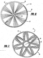
- the weaving pattern as shown in Figures 2, 3 and 4 may be altered to create more or less blades or may be altered to produce the alternative embodiments shown in Figures 7 and 18a-18q , many of which include a hollow cylindrical center portion 25 (see Figure 7 ).
- the alternative embodiment of Figure 7 has impeller 21 formed by fiber 12, and has blade portions 24 and a shroud portion 23. Additional uses for the alternative embodiment of Figure 7 include a drive shaft that may be integrally woven in the area of cylindrical hollow 25 as a single piece or a drive shaft that may be attached in such an area 25 to the impeller.
- the preferred embodiment process for woven impeller 10 sequentially includes fiber creation, fiber wetting, fiber winding/weaving and curing.
- a spool 201 containing continuous fiber 12 is automatically fed into a resin bath 203.
- Resin bath 203 is preferably a tank containing resin 205 or other coating which will stick to at least the outside of fiber 12. Alternately, resin 205 can be sprayed or otherwise deposited onto fiber 12.
- resin is added in a liquid or gel form prior to or during the weaving process which is known in the art as "wetting weaving” or “fiber wetting.”
- the resin is self-hardening so that the woven impeller hardens over time after weaving and then is removed from a jig 217 in a hardened form.
- the resin may be an epoxy type resin such that it has two components which create the adhesion or self-hardening.
- the resin may be hardened by temperature and the woven impeller on a jig may be placed in an oven to enhance hardening.
- the resin may be hardened through use of ultraviolet light. It is noteworthy that a mold is not required, thereby reducing capital expense and manufacturing complexity.
- Fiber 12 may be a prefabricated fiber with a PVC coating or other polymeric coating which is on the fiber and has any of the properties and hardening techniques as described above for resins.
- the resin, PVC or polymeric material may optionally contain electromagnetic or conductive particles and properties.
- the weaving or layering over jig 217 may-include pins that are curved to help give a curved shape to a blade or vane of the impeller.
- the fiber(s) is woven on a hollow and rigid plastic tube 219 with slots and such a plastic tube becomes part of the impeller, and acts as the primary shroud portion with the fibers acting as the blade portions.
- the fiber(s) are secured in the slots and may or may not be severed at the tube to avoid sharp-angle turns.
- the plastic tube may optionally contain magnetic or electromagnetic properties.
- a fiber placement process automatically places and winds multiple individual, resin-coated tows or fiber segments 91 onto the jig 93 or a mandrel 94 at high speed, using a numerically controlled, automatically controlled placement head to dispense, clamp, cut and restant each tow during placement.
- Minimum cut length (the shortest tow length a machine can lay down) is the essential ply-shape determinant.
- the fiber placement heads 95 are attached to a 5-axis gantry or retrofitted to a filament winding machine 97.
- Machines are available with dual mandrel stations to increase productivity and a two spool, five axis filament winding machine would be desirable, especially if a conductive/magnetic fiber is also employed.
- a WSH-Super Hornet Winder filament winding machine which can be obtained from McClean Anderson Inc., is the preferred existing machine that is currently known but it should be appreciated that many other similar machines can be employed.
- Advantages of automated fiber placement fabrication include speed, reduced material scrap and labor costs, parts consolidation and improved part-to-part uniformity.
- High-strength fibers used in advanced composites include not only carbon, glass and aramid, but high-modulus polyethylene (“PE”), boron, quartz, ceramic, newer fibers such as poly p-phenylene-2,6-benzobisoxazole (“PBO”), hybrid combinations, and the like.
- PE polyethylene
- PBO poly p-phenylene-2,6-benzobisoxazole
- the basic fiber forms for high-performance composite applications are bundles of continuous fibers called tow.
- Carbon fiber tow consists of thousands of continuous untwisted filaments, with the filament count designated by a number followed by "K,” indicating multiplication by 1,000(e.g., 12K indicates a filament count of 12,000).
- Carbon fiber is produced from a variety of precursors, including polyacrytonitrile ("PAN”),rayon and pitch.
- PAN polyacrytonitrile
- the precursor fibers are heated and stretched to create the high-strength fibers.
- PAN-based carbon fibers offer a range of properties, including good-to-excellent strength - to 1,000 ksi - and high stiffness.
- Pitch fibers made from petroleum or coal tar pitches, have high-to-extremely-high stiffness and low-to-negative axial CTE.
- Typical aerospace-grade tow size ranges from 1K to 12K.
- PAN- and pitch-based 12K carbon fibers are available with a moderate (33 to 35 Msi), intermediate (40 to 50 Msi), high (50 to 70 Msi) and ultrahigh (70 to 140 Msi) modulus.
- Mode is the mathematical value that describes the stiffness of a material by measuring its deflection or change in length under loading.
- Heavy tow carbon fibers have filament counts from 48K up to 320K to 35-Msi modulus and 550-ksi tensile strength.
- Aramid fibers composed of aromatic polyamide, provide exceptional impact resistance and tensile strength.
- Standard high-performance aramid fiber has a modulus of about 20 Msi and tensile strength of approximately 500 ksi.
- Commercially available high-strength, high-modulus polyethylene fibers are known for being extremely light weight, as well as for their excellent chemical and moisture resistance, outstanding impact resistance, anti-ballistic properties and low dielectric constant.
- PE fibers have relatively low resistance to elongation under sustained loading, and the upper limit of their use temperature range is about 98°C/210°F.
- Quartz-fibers while more expensive than glass, have lower density, higher strength and higher stiffness than E-glass, and about twice the elongation-to-break, making them a good choice where durability is a priority. Quartz fibers also have a near-zero CTE; they can maintain their performance properties under continuous exposure to temperatures as high as 1050°C/1920°F and up to 1250°C/2280°F, for short time periods. Quartz fibers possess significantly better electromagnetic properties than glass. Ceramic fibers offer high to very high temperature resistance but low impact resistance and relatively poor room-temperature properties.
- PBO is a relatively new fiber, with modulus and tensile strength almost double that of aramid fiber and a decomposition temperature almost 100°C/212°F higher. It is suitable for high-temperature applications.
- Basalt fiber is an inexpensive fiber, similar to glass, but which exhibits better chemical and alkali resistance than glass.
- Boron fibers are five times as strong and twice as stiff as steel. They are made by a chemical vapor-deposition process in which boron vapors are deposited onto a fine tungsten or carbon filament. Boron provides strength, stiffness and is light weight, possessing excellent compressive properties and buckling resistance.
- Fiber hybrids capitalize on the best properties of various fiber types, and may reduce raw material costs. Hybrid composites may combine carbon/aramid and carbon/glass fibers.
- Natural fibers -sisal, hemp, kenaf, flax, jute and coconut are the most common - are derived from the bast or outer stem of certain plants. They have the lowest density of any structural fiber but possess sufficient stiffness and strength for some applications. All of the fibers discussed hereinabove can be used with the present invention depending upon the usage requirements and operating conditions.
- the impeller fiber layers or segments are held together by cross-stitching.
- the cross-stitching may be a fiber that is similar to the impeller that is woven perpendicular to the vanes.
- the cross-stitching includes an electromagnetic or conductive fiber that is different than fiber 12, as will be further described hereinafter with regard to Figure 8 .
- the cross weave may be a fiber made of a Nylon engineering grade polymer or another lightweight and strong material.
- the impeller may be generally rigid and in other embodiments, it may be generally non-rigid and flexile or pliable.
- the woven fiber impeller spins into shape when rotated in a compressor and, when not being rotated, it folds in an umbrella-like manner so that it does not impede fluid flow therepast.
- a non-rigid impeller is cross-stitched as opposed to using a hardening resin material on the fiber for a rigid impeller.
- a second preferred embodiment woven impeller 15 includes a magnetic, electromagnetically energizable, or conductive fiber 16 woven into shroud 11.
- Fiber 16 as shown in Figures 5 and 6 , is an individual and separate member woven or placed in alternating layers to continuous, nonconductive fiber 12.
- Fiber 16 is preferably an elongated and continuous fiber which is resin coated.
- Fiber 12 is woven such that it creates blades 13 and peripheral shroud 11. Thus, fibers 12 and 16 integrally create blades 13 and shroud 11 as a single piece.
- FIGs 8, 9 and 21 an additional third preferred embodiment of impeller 27 is shown.
- impeller 27 as multiple, shorter electromagnetic or conductive fibers 31 generally perpendicularly woven into fibers 12 of peripheral shroud 11. Impeller 27 is formed by weaving fiber 12 thereby creating blades 13, with a centerpoint 14 (coinciding with its rotational axis) and-shroud 11 with engaged fibers 31 permanently integrated therein. Fibers 12 and 31 are coated with a resin 251 by wetting.
- An alternate embodiment is shown in Figure 20 wherein an induction wire 253 of copper, steel, aluminum or alloys thereof, surrounds a majority or more of the stacked segment layers of nonconductive, carbon fiber 12 at multiple spaced apart locations of the shroud. A wetted resin coating binds the segments and fibers together.
- a fourth preferred embodiment impeller 261 of the present invention includes one or more continuous nonconductive fibers 263 woven to define sixteen, spaced apart and curved blades 265, flow-through passages 267 with flow dividers 269, a hub area 271 and a peripheral should 273 of circular-cylindrical shape.
- the shroud can be severed, remove and discarded from the remainder of the impeller. It is desired to tightly and closely stack the fiber segments upon each other with minimal space between in order to reduce fluid flow between the layered segments. Any remaining gaps are filled in by the resin coating from the fiber wetting process.
- the pitch of each blade is set by slightly offsetting the angle or degree of rotation of each fiber layer segment relative to the previously placed layer segment from bottom to top.
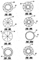
- Figure 18e shows an eight-point star pattern of blades 295 (of about 90° outer angle ⁇ ') with a large transversely spaced hub area 297
- Figure 18f illustrates an eight-point star pattern of blades 299 (of about 45° outer angles ⁇ ") with an intermediate transversely spaced hub areas 301.
- a pie-shaped and centrally crossing configuration of six blades 303 can be observed in Figure 18g
- a nine pointed pattern of blades 305 (of obtuse outer angles ⁇ ''') with a large transversely spaced hub area 307 is shown in Figures 18h .
- Figures 18h, 18i, 18k, 18m, 18n, 18o 18p and 18q illustrate star patterned blades 309, 311, 313, 315, 317, 319, 321 and 323, respectively, of nine, ten, ten, eleven, eleven, eleven and nine-points respectively.
- Variations of pie configurations of centrally crossing blades 331 and 335 are shown in Figure 18j and 18l , respectively, with ten and eight blades, respectively.
- the shrouds may remain attached to the blades as a single piece or may be cut off after manufacturing.
- the blades preferably have curved shapes and rotate about a central axis during operation.
- the shapes and patterns of these blades are significant by minimizing undesired fiber layer segment-to-adjacent segment gaps and gaps, and to minimize shroud-to-blade turn fillets (to maximize working blade surface area, while maximizing axial fluid-flow through desired impeller areas).
- Conductive or magnetic fibers and/or resin with such particles are optionally applied to any of these embodiments.
- Water as a refrigerant (R718) is very beneficial because it is natural, absolutely harmless to man and nature, easily available and there are no problems disposing it after use. Also it allows the use of high-efficient direct heat exchangers since cold water, refrigerant and cooling water all are the same fluid, mostly just water taken from the tap.
- relatively high pressure ratios are required since the cycle works under a coarse vacuum; they are approximately twice as high as pressure ratios when using classical refrigerants like R134a or R12. Combined with the thermodynamic properties of water vapor, this high pressure ratio requires approximately a two to four times higher circumferential speed of the turbocompressor impeller or wheel, which can only be achieved economically by new special high-performance turbocompressors.
- the high pressure cooling water may be introduced dynamically short before the vapor inlet port is closed - meaning before the compression shock wave propagating into the vapor faster than the phase interface reached the trailing edge of the vapor inlet port.
- the rotor axis may be vertical and the water may be injected from the bottom. After the vapor is precompressed by a primary shock wave and halted, the incoming water may compress the vapor further and fully condense it, depending on what kind of wave rotor has been chosen.
- a pump supplies the high pressure to the cooling liquid. Its energy consumption might be considered negligible, since the liquid is incompressible.
- Alternate impeller 461 and stator 463 shapes are shown in Figure 22 , where there are matching concave and convex (or diagonal) adjacent surfaces. This works best with no shroud on the final impeller blades 465. When two or more of such impellers are rotated about their coaxial axis 467, the fluid flows through the circumferential gap 469 and is compressed by blades 465, as is illustrated in the variations of Figures 23 and 24 .
- the woven composite impellers of the present invention are advantageous in chillers and other compressor systems.
- the majority of forces seen by conventional impellers are not from the gas passing through the blades but from forces acting in its radial direction due to its own inherent mass rotating at high speeds.
- a lightweight and strong impeller overcomes this disadvantage.
- the lightweight nature of the present invention impellers reduce safety issues arising from using heavy materials and reduces the forces inflicted on the impeller bearings.
- the present invention lightweight materials also reduce the need for extensive balancing. While the preferred fiber materials have been disclosed for the impeller, it is alternately envisioned that a biodegradable impeller can be created from a biomass matrix such as a soy bean polymer, flax or cotton fiber, for use in some applications.
Landscapes
- Engineering & Computer Science (AREA)
- Mechanical Engineering (AREA)
- General Engineering & Computer Science (AREA)
- Ceramic Engineering (AREA)
- Structures Of Non-Positive Displacement Pumps (AREA)
- Turbine Rotor Nozzle Sealing (AREA)
Description
- The present invention generally relates to compressors, both apparatuses and methods of use, and more specifically, to compressor impellers.
- Compressors are machines that increase the pressure of a gas, vapor or mixtures of gases and vapors. The pressure of the fluid is increased by reducing the fluid's specific volume during passage of the fluid through the compressor. A cone shaped cylinder with fan blades or an impeller is an integral part in many compressors since it helps with air intake and compression fluid, as well as directing the flow through the compressor. Depending on the application, impellers may be made of many different materials such as metals or polymers and are typically fabricated by either casting, molding or machining the material.
- The following
U.S. patents disclose rotated members with woven fibers: 3,632,460 entitled "Epicyclic Weaving of Fiber Discs" which issued to Palfreyman et al. on January 4, 1972 ;3,718,952, with the same title, which issued to Palfreyman et al. on March 6, 1973 ;4,460,531, entitled "Composite Fiber Reinforced Propeller," which issued to Harris et al. on July 17, 1984 ;4,255,087, entitled "Member Formed of Fiber-Reinforced Plastic Material, such as a Rotor Blade," which issued to Wackerle et al. on March 10, 1981 ; and5,464,325, entitled "Turbo-Compressor Impeller for Coolant," which issued to Albring et al. on November 7, 1995 . These prior devices, however, are believed to be prohibitively expensive to produce in volume and do not benefit from inclusion of multifunctional component integration. Furthermore, these prior constructions employ an expensive metal coating, polymeric over-molding or a composite material, applied after fiber placement, which constitutes a greater portion of the part as compared to the fiber portion and is complicated to produce. What is needed is an impeller that is fabricated by a less expensive method other than casting or molding. - In accordance with the present invention, an impeller as defined in
claim 1 is provided that may be used in compressors or turbines. In another aspect of the present invention, a method of manufacturing an impeller is presented inclaim 24. - The woven impeller of the present invention is advantageous over prior devices since the present invention is less expensive to manufacture, in part due to material differences, geometric variations and processing simplicity. The present invention impeller is also advantageous by integrating components into a multi-functional, single part. For example, conductive and/or magnetic fiber members or particle members, a shroud and/or multiple blades, are woven together by the same structural fiber or bundle of fibers. Also, electric motor integration into the impeller is employed. Moreover, sharp angles and corners can be achieved with various embodiments of the present -invention. Furthermore, no molds, prepregs, or post-weaving coatings, moldings or structural assembly are required. Fluid flow is additionally improved through the weaving patterns and/or hub design. Further advantages and areas of applicability of the present invention will become apparent from the figures, detailed description and claims provided hereinafter. It should be understood that the detailed description and specific examples, while indicating various embodiments of the invention, are intended for purposes of illustration only and are not intended to limit the scope of the invention.
- The present invention will become more fully understood from the detailed description and the accompanying drawings, wherein:
-
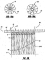
Figure 1 is a perspective view showing a first preferred embodiment of a woven impeller of the present invention; -
Figure 2 is a perspective view showing a beginning step of weaving a fiber into the first preferred embodiment of the woven impeller; -
Figure 3 is a perspective view showing a further step in weaving the fiber into the first preferred embodiment of the woven impeller; -
Figure 4 is a perspective view showing one completed fiber layer of the first preferred embodiment of the woven impeller; -
Figure 5 is a perspective view showing a second illustrative embodiment of a woven impeller with an electromagnetic or conductive material; -
Figure 6 is a front elevational view showing the second embodiment of the woven impeller ofFigure 5 ; -
Figure 7 is a front elevational view showing an alternate embodiment of a woven impeller; -
Figure 8 is a perspective view showiwg a third illustrative embodiment of a woven impeller, with an electromagnetic or conductive fiber; -
Figure 9 is a front elevational view showing the third embodiment woven impeller ofFigure 8 ; -
Figure 10 is a diagrammatic side view showing a generic embodiment; -
Figure 11 is a block diagram showing an alternate, four port wave rotor system employed with a condensing wave rotor system; -
Figure 12 is a block diagram showing a three port wave rotor system employed with a condensing wave rotor system; -
Figure 13 is a diagrammatic side view showing a first illustrative embodiment of the condensing wave rotor system, illustrating a woven wave rotor impeller; -
Figure 14 is a diagrammatic side view showing a second illustrative embodiment of the condensing wave rotor system, illustrating a woven wave rotor impeller; -
Figure 15 is a diagrammatic side view showing a third illustrative embodiment of the condensing wave rotor system, illustrating a woven wave rotor impeller; -
Figure 16 is a diagrammatic side view showing a fourth illustrative embodiment of the condensing wave rotor system, illustrating a woven wave rotor impeller; -
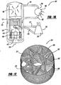
Figure 17 is a perspective view showing a fourth illustrative embodiment of a woven impeller; -
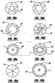
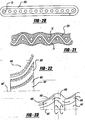
Figure 18a-18q are diagrammatic top views showing alternate embodiment woven impellers; -
Figure 19 is a diagrammatic, cross-sectional view showing another alternate embodiment woven impeller of the present invention, employed with an electric motor of the condensing wave rotor system; -
Figures 20 is a diagrammatic, cross-sectional view showing another alternate embodiment woven impeller; -
Figure 21 is a diagrammatic, cross-sectional view of the third illustrative embodiment woven impeller ofFigures 8 and 9 ; -
Figure 22 is a diagrammatic cross-sectional view showing a further alternate embodiment woven impeller, employed with an electric motor of the condensing wave rotor system; -
Figures 23 and24 are diagrammatic, cross-sectional views showing fluid flow paths through a series of woven impellers in two variations of the condensing wave rotor systems; -
Figures 25 and 26 are diagrammatic side views showing illustrative embodiments of fiber wetting processing for a woven impeller of the present invention; -
Figures 27 is a fragmentary, perspective view showing a fiber winding machine for a woven impeller of the present invention; -
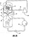
Figure 28 is a diagrammatic view showing another illustrative embodiment condensing wave rotor system; and -
Figure 29 is an exploded, perspective view showing an axial wave rotor employed in all of the illustrative condensing wave rotor systems disclosed herein. - The following description of the various embodiments is merely exemplary in nature and is in no way intended to limit the invention, its application, or uses. The present invention provides a woven impeller and a method of manufacturing such an impeller.
- The present invention provides woven impellers for use in compressors and more particularly, a condensing wave rotor system. Compressors are used to increase pressure of a wide variety of gases and vapors for a multitude of purposes. A refrigeration compressor is used to compress a gas formed in the evaporator. Other applications of compressors include chemical processing, gas transmission, gas turbines, turbochargers, and construction. Compressors that accelerate the fluid in a direction generally parallel to the rotating shaft consist of pairs of moving and stationary blade rows, each forming a stage. An impeller is a rotating member of a turbine, blower, fan, axial or centrifugal pump, or mixing apparatus. An impeller may also be known as a rotor.
- Referring to
Figure 1 , animpeller 10 is woven from afiber 12 and includes eight blade orportions 13 and a duct orshroud portion 11 which surrounds the blades.Fiber 12 is woven to formblades 13 andshroud 11, andfiber 12 crosses in thecenter 14 with segments thereof overlapping each other. The blades and shroud are made as an integral, single piece.Figures 2, 3 and4 show howfiber 12 is woven to createperipheral shroud portion 11 andblade portions 13. Weaving may be done on a jig designed for such a pattern and woven by hand or preferably the weaving is done on a turn key system such as an automated machine that is designed to create impeller. The weaving pattern as shown inFigures 2, 3 and4 may be altered to create more or less blades or may be altered to produce the alternative embodiments shown inFigures 7 and 18a-18q , many of which include a hollow cylindrical center portion 25 (seeFigure 7 ). The alternative embodiment ofFigure 7 hasimpeller 21 formed byfiber 12, and hasblade portions 24 and ashroud portion 23. Additional uses for the alternative embodiment ofFigure 7 include a drive shaft that may be integrally woven in the area of cylindrical hollow 25 as a single piece or a drive shaft that may be attached in such anarea 25 to the impeller. - The preferred embodiment process for woven
impeller 10 sequentially includes fiber creation, fiber wetting, fiber winding/weaving and curing. As can be observed inFigure 25 , aspool 201 containingcontinuous fiber 12 is automatically fed into aresin bath 203.Resin bath 203 is preferably atank containing resin 205 or other coating which will stick to at least the outside offiber 12. Alternately,resin 205 can be sprayed or otherwise deposited ontofiber 12. - An alternate manufacturing process is shown in
Figure 26 wherein afirst matrix material 207 of pure resin is applied tofiber 12 by way of a fist tank anddispenser assembly 209, andsecond matrix material 211 with ground reinforcing, magnetic or conductive particles, is subsequently or simultaneously applied tofiber 12 via a second tank anddispenser assembly 213. The flow ofassemblies valves 215. - More specifically, resin is added in a liquid or gel form prior to or during the weaving process which is known in the art as "wetting weaving" or "fiber wetting." The resin is self-hardening so that the woven impeller hardens over time after weaving and then is removed from a
jig 217 in a hardened form. In other embodiments, the resin may be an epoxy type resin such that it has two components which create the adhesion or self-hardening. The resin may be hardened by temperature and the woven impeller on a jig may be placed in an oven to enhance hardening. Alternately, the resin may be hardened through use of ultraviolet light. It is noteworthy that a mold is not required, thereby reducing capital expense and manufacturing complexity.Fiber 12 may be a prefabricated fiber with a PVC coating or other polymeric coating which is on the fiber and has any of the properties and hardening techniques as described above for resins. In any of the above embodiments, the resin, PVC or polymeric material may optionally contain electromagnetic or conductive particles and properties. The weaving or layering overjig 217 may-include pins that are curved to help give a curved shape to a blade or vane of the impeller. In another variation, the fiber(s) is woven on a hollow and rigidplastic tube 219 with slots and such a plastic tube becomes part of the impeller, and acts as the primary shroud portion with the fibers acting as the blade portions. The fiber(s) are secured in the slots and may or may not be severed at the tube to avoid sharp-angle turns. The plastic tube may optionally contain magnetic or electromagnetic properties. - As can be viewed in
Figures 25 and27 , a fiber placement process automatically places and winds multiple individual, resin-coated tows orfiber segments 91 onto thejig 93 or amandrel 94 at high speed, using a numerically controlled, automatically controlled placement head to dispense, clamp, cut and restant each tow during placement. Minimum cut length (the shortest tow length a machine can lay down) is the essential ply-shape determinant. The fiber placement heads 95 are attached to a 5-axis gantry or retrofitted to afilament winding machine 97. Machines are available with dual mandrel stations to increase productivity and a two spool, five axis filament winding machine would be desirable, especially if a conductive/magnetic fiber is also employed. A WSH-Super Hornet Winder filament winding machine, which can be obtained from McClean Anderson Inc., is the preferred existing machine that is currently known but it should be appreciated that many other similar machines can be employed. Advantages of automated fiber placement fabrication include speed, reduced material scrap and labor costs, parts consolidation and improved part-to-part uniformity. - To achieve desirable properties in composite components, adhesion between fiber and matrix should be optimized. Proper adhesion requires that sufficient saturation with resin (wetout) at the fiber-matrix interface is achieved. To ensure good adhesion, attention is given to fiber surface preparation, such as the use of a surface finish or coupling agent, often termed sizing. Sizing, applied to glass and carbon filaments immediately after their formation, serves three purposes: as it enhances the fiber/matrix bond, it also eases processing and protects the fibers from breakage during processing. Although it accounts for only 0.25 to 6.0 percent of total fiber weight, sizing is a dynamic force in fiber reinforcement performance. Sizing chemistry can be optimized for manufacturing processes such as pultrusion, filament winding and weaving.
- High-strength fibers used in advanced composites include not only carbon, glass and aramid, but high-modulus polyethylene ("PE"), boron, quartz, ceramic, newer fibers such as poly p-phenylene-2,6-benzobisoxazole ("PBO"), hybrid combinations, and the like. The basic fiber forms for high-performance composite applications are bundles of continuous fibers called tow. Carbon fiber tow consists of thousands of continuous untwisted filaments, with the filament count designated by a number followed by "K," indicating multiplication by 1,000(e.g., 12K indicates a filament count of 12,000).
- Carbon fiber is produced from a variety of precursors, including polyacrytonitrile ("PAN"),rayon and pitch. The precursor fibers are heated and stretched to create the high-strength fibers. PAN-based carbon fibers offer a range of properties, including good-to-excellent strength - to 1,000 ksi - and high stiffness. Pitch fibers, made from petroleum or coal tar pitches, have high-to-extremely-high stiffness and low-to-negative axial CTE. Typical aerospace-grade tow size ranges from 1K to 12K. PAN- and pitch-based 12K carbon fibers are available with a moderate (33 to 35 Msi), intermediate (40 to 50 Msi), high (50 to 70 Msi) and ultrahigh (70 to 140 Msi) modulus. (Modulus is the mathematical value that describes the stiffness of a material by measuring its deflection or change in length under loading.) Heavy tow carbon fibers have filament counts from 48K up to 320K to 35-Msi modulus and 550-ksi tensile strength.
- Aramid fibers, composed of aromatic polyamide, provide exceptional impact resistance and tensile strength. Standard high-performance aramid fiber has a modulus of about 20 Msi and tensile strength of approximately 500 ksi. Commercially available high-strength, high-modulus polyethylene fibers are known for being extremely light weight, as well as for their excellent chemical and moisture resistance, outstanding impact resistance, anti-ballistic properties and low dielectric constant. However, PE fibers have relatively low resistance to elongation under sustained loading, and the upper limit of their use temperature range is about 98°C/210°F. Quartz-fibers, while more expensive than glass, have lower density, higher strength and higher stiffness than E-glass, and about twice the elongation-to-break, making them a good choice where durability is a priority. Quartz fibers also have a near-zero CTE; they can maintain their performance properties under continuous exposure to temperatures as high as 1050°C/1920°F and up to 1250°C/2280°F, for short time periods. Quartz fibers possess significantly better electromagnetic properties than glass. Ceramic fibers offer high to very high temperature resistance but low impact resistance and relatively poor room-temperature properties.
- PBO is a relatively new fiber, with modulus and tensile strength almost double that of aramid fiber and a decomposition temperature almost 100°C/212°F higher. It is suitable for high-temperature applications. Basalt fiber is an inexpensive fiber, similar to glass, but which exhibits better chemical and alkali resistance than glass. Boron fibers are five times as strong and twice as stiff as steel. They are made by a chemical vapor-deposition process in which boron vapors are deposited onto a fine tungsten or carbon filament. Boron provides strength, stiffness and is light weight, possessing excellent compressive properties and buckling resistance. Fiber hybrids capitalize on the best properties of various fiber types, and may reduce raw material costs. Hybrid composites may combine carbon/aramid and carbon/glass fibers. Natural fibers -sisal, hemp, kenaf, flax, jute and coconut are the most common - are derived from the bast or outer stem of certain plants. They have the lowest density of any structural fiber but possess sufficient stiffness and strength for some applications. All of the fibers discussed hereinabove can be used with the present invention depending upon the usage requirements and operating conditions.
- In another preferred embodiment, the impeller fiber layers or segments are held together by cross-stitching. The cross-stitching may be a fiber that is similar to the impeller that is woven perpendicular to the vanes. In some of the embodiments, the cross-stitching includes an electromagnetic or conductive fiber that is different than
fiber 12, as will be further described hereinafter with regard toFigure 8 . The cross weave may be a fiber made of a Nylon engineering grade polymer or another lightweight and strong material. The impeller may be generally rigid and in other embodiments, it may be generally non-rigid and flexile or pliable. In embodiments in which the impeller is non-rigid, the woven fiber impeller spins into shape when rotated in a compressor and, when not being rotated, it folds in an umbrella-like manner so that it does not impede fluid flow therepast. Typically, a non-rigid impeller is cross-stitched as opposed to using a hardening resin material on the fiber for a rigid impeller. - Referring to
Figures 5 and6 , a second preferred embodiment wovenimpeller 15 includes a magnetic, electromagnetically energizable, orconductive fiber 16 woven intoshroud 11.Fiber 16, as shown inFigures 5 and6 , is an individual and separate member woven or placed in alternating layers to continuous,nonconductive fiber 12.Fiber 16 is preferably an elongated and continuous fiber which is resin coated.Fiber 12 is woven such that it createsblades 13 andperipheral shroud 11. Thus,fibers blades 13 andshroud 11 as a single piece. Referring toFigures 8, 9 and21 , an additional third preferred embodiment ofimpeller 27 is shown. In this embodiment,impeller 27 as multiple, shorter electromagnetic orconductive fibers 31 generally perpendicularly woven intofibers 12 ofperipheral shroud 11.Impeller 27 is formed by weavingfiber 12 thereby creatingblades 13, with a centerpoint 14 (coinciding with its rotational axis) and-shroud 11 with engagedfibers 31 permanently integrated therein.Fibers resin 251 by wetting. An alternate embodiment is shown inFigure 20 wherein aninduction wire 253 of copper, steel, aluminum or alloys thereof, surrounds a majority or more of the stacked segment layers of nonconductive,carbon fiber 12 at multiple spaced apart locations of the shroud. A wetted resin coating binds the segments and fibers together. - A fourth
preferred embodiment impeller 261 of the present invention, includes one or more continuousnonconductive fibers 263 woven to define sixteen, spaced apart andcurved blades 265, flow-throughpassages 267 withflow dividers 269, ahub area 271 and a peripheral should 273 of circular-cylindrical shape. In a variation, the shroud can be severed, remove and discarded from the remainder of the impeller. It is desired to tightly and closely stack the fiber segments upon each other with minimal space between in order to reduce fluid flow between the layered segments. Any remaining gaps are filled in by the resin coating from the fiber wetting process. The pitch of each blade is set by slightly offsetting the angle or degree of rotation of each fiber layer segment relative to the previously placed layer segment from bottom to top. -
Figure 18a-18q illustrate various alternate embodiment blade patterns each within ashroud 281. A five-point star pattern ofblades 283 is shown inFigure 18a , a six-point star pattern ofblades 285 is shown inFigure 18b , a seven-point star pattern ofblades 287 with a large transversely spacedhub area 289 are illustrated inFigure 18c , and a seven-point star pattern of blades 291 (of acute outer angles α) with a small transversely spacedhub area 293 are illustrated inFigure 18d . Furthermore,Figure 18e shows an eight-point star pattern of blades 295 (of about 90° outer angle α') with a large transversely spacedhub area 297, andFigure 18f illustrates an eight-point star pattern of blades 299 (of about 45° outer angles α") with an intermediate transversely spacedhub areas 301. A pie-shaped and centrally crossing configuration of sixblades 303 can be observed inFigure 18g , and a nine pointed pattern of blades 305 (of obtuse outer angles α''') with a large transversely spacedhub area 307 is shown inFigures 18h . Similarly,Figures 18h, 18i, 18k, 18m, 18n, 18o 18p and 18q illustrate star patternedblades blades Figure 18j and 18l , respectively, with ten and eight blades, respectively. The shrouds may remain attached to the blades as a single piece or may be cut off after manufacturing. The blades preferably have curved shapes and rotate about a central axis during operation. The shapes and patterns of these blades are significant by minimizing undesired fiber layer segment-to-adjacent segment gaps and gaps, and to minimize shroud-to-blade turn fillets (to maximize working blade surface area, while maximizing axial fluid-flow through desired impeller areas). Conductive or magnetic fibers and/or resin with such particles are optionally applied to any of these embodiments. - Advantages of a woven impeller include the ability to perform scalable, automatic, cheap rapid prototyping and/or mass production of high strength, lightweight turbomachine impellers. Other advantages include easy integration of electromagnetic motor bearing elements during the manufacturing process. In addition, active coils may be easily separated from fluid flow. In some embodiments, a drive shaft and components sealing such a shaft may be eliminated which can also lead to simplifying the dynamic system. In some embodiments, the impeller may include electromagnetic bearings or aerodynamic bearings which may be used to compensate for manufacturing imbalances. In a preferred embodiment, the woven impeller comprises a fiber that is about 3 millimeters thick. In alternate embodiments, the woven impeller is comprised of fibers that are less than one millimeter thick. In some embodiments, the woven impeller comprises a single continuous fiber and in other embodiments, the woven impeller comprises one continuous fiber and a second continuous fiber that has electromagnetic properties. The transverse impeller diameter may range from about one meter or greater to about a centimeter or less. Various applications of such an impeller include a turbomachine, turbocharger, turbochiller, a turbine, a compressor, a pump, a fan, a blower, a jet engine, or any other such application that impellers or other rotatable members are commonly used in the art.
- The condensing wave rotor system which preferably employs a woven impeller, is hereinafter described. Mechanical refrigeration is primarily an application of thermodynamics wherein the cooling medium, or refrigerant, goes through a cycle so that it can be recovered for re-use. Commonly used basic cycles in order of importance are vapor compression, absorption, steam jet or steam injector, and air. Each cycle operates between two pressure levels, and all except the air cycle uses two phase working medium which alternates cyclically between the vapor liquid and the vapor phases.
- Water as a refrigerant (R718) is very beneficial because it is natural, absolutely harmless to man and nature, easily available and there are no problems disposing it after use. Also it allows the use of high-efficient direct heat exchangers since cold water, refrigerant and cooling water all are the same fluid, mostly just water taken from the tap. As a challenge, relatively high pressure ratios are required since the cycle works under a coarse vacuum; they are approximately twice as high as pressure ratios when using classical refrigerants like R134a or R12. Combined with the thermodynamic properties of water vapor, this high pressure ratio requires approximately a two to four times higher circumferential speed of the turbocompressor impeller or wheel, which can only be achieved economically by new special high-performance turbocompressors. However, most air-conditioning applications require two, bulky and complete radial compressor stages with intercooling. The isentropic efficiencies of the turbocompressors are substantially limited by the required high pressure ratios and the efficiency of the pressure recovery of the steady-flow diffusers, which decelerate the high speed vapor flow coming from the high-speed compressor impellers. Hence, flow boundary layers cannot withstand such a high pressure rise and tend to separate more easily from the walls and vanes of such steady flow devices, thereby reducing the compressor efficiency further.
- The key component of a R718 turbochiller is the compressor. Water as the refrigerant has some specific features that complicate this application in refrigeration plants with turbocompressors. Since the cycle works under course vacuum, volumetric cooling capacity of water vapor is very low and hence huge volume flows have to be compressed with relatively high pressure ratios. As compared with classic refrigerants like R134a or R12, the use of water (R718) as a refrigerant requires approximately 200 times higher volume flow and about double the pressure ratio for the same applications. Due to thermodynamic properties of water vapor, this high pressure ratio requires approximately a 2 to 4 times higher compressor tip speed, depending on impeller design, while the speed of sound is approximately 2.5, times higher by way of comparison. Reynolds numbers are about 300 times lower and the specific work transmission per unit mass has to be about 15 times higher. One way to solve this traditional problem is shown in
Figure 10 . Ageneric turbochiller 30 has a chilledwater cycle 37, afirst compressor 91, arefrigerant cycle 36, asecond compressor 32, and a coolingwater cycle 35. Coolingwater cycle 35 andchilled water cycle 37 are connected via expansion-valve 39. Referring tochilled water cycle 37, aheat source 43 heats water which flows throughstream 45 into anevaporator 42. Evaporated water then entersfirst compressor 91. Water that is not forced through the compressor is collected and cycled throughpipe 46 back to the heat source. After the evaporated water entersfirst compressor 91, it is compressed and is refrigerated through anintercooler area 41 which then is forced intosecond compressor 32 incompressor condenser area 40. Water vapor that condenses inintercooler region 41 is collected into a collection area that is connected to cooler watercycle collection area 49. An exemplary water refrigeration system is disclosed inU.S. Patent No. 6,427,453 entitled "Vapor-Compression Evaporative Air Conditioning Systems and Components" which issued to Holtzapple et al. on August 6, 2002, which is incorporated by reference herein. Any of the previously disclosed woven impellers of the present invention may be employed by thecompressors 91 and/or 32 inturbochiller 30, even without a wave rotor. - A wave rotor offers great potential and advantages for a condensing wave rotor system in a refrigeration systems, since it exploits the enormous density differences of gaseous and liquid fluid by the action of centrifugal forces. This greatly supports the separation of vapor and condensed fluid in the scavenging process and channel drying before refilling, which addresses a concern in handling of phase-changes occurring in both directions in axial wave rotors.
- Utilizing time-depended flow features, wave rotors represent a promising technology for increasing the overall pressure ratio and the efficiency of the pressure recovery. As discussed above, for the same inlet and outlet Mach numbers, the pressure gain in time-dependent flow devices can be much higher than that obtained in steady flow devices. This also may allow for a lower total pressure ratio of the compressor impeller, which is usually associated with a higher isentropic efficiency of the compressor impeller assuming its aerodynamic quality stays the same (e.g., the same polytropic efficiency). This increases the overall efficiency. Furthermore, the combination of this may then also permit the use of more compact novel axial compressors with less stages and will further promote the new environmental friendly and energy efficient R718-technology for refrigeration, air-conditioning and heat pump applications of capacities <500 kW, which is hardly available today in form of an economical solution.
- A wave rotor is a device that utilizes unsteady wave motion to exchange energy by direct work action between fluids. A wave rotor consists of an array of channels on the periphery of a rotor. As the wave rotor rotates, the ends of the channels are periodically ported to high and low pressure manifolds or ducts which generate and utilize waves in the channels. These pressure exchanging wave rotors are typically used as a topping unit to enhance the performance of a gas turbine engine. As a topping cycle in a gas turbine engine, the air from the engine compressor is directed into the wave rotor through a first port. The air flows into the channels of the rotor and is compressed by a series of compression or shock waves. This air leaves the wave rotor through a second port at a higher pressure than when it entered the wave rotor and passes to a burner or combustor. After being heated in the burner, the gas returns to the wave rotor through a third port, driving a shock into the air residing in the channels. This gas is trapped within the channels as the third port closes at a high pressure. When the wave rotor rotates around to a fourth port, the gas expands out into the relatively lower static pressure in the fourth port and flows to the high-pressure engine turbine. In passing through the wave rotor, the air is first compressed and then expanded thus, the wave rotor combines in a single device the functions performed by the compressor and turbine in a high spool. By using a wave rotor topping cycle, combustion temperatures greater than the turbine inlet temperature can be used since the gas leaving the combustor is cooled in expansion before being sent to the turbine. Also, since the rotor is washed alternately by cool inlet air and hot combustion gas, it is self-cooled and obtains a steady state temperature significantly lower than the combustion temperature.
- The basic concept underlying wave rotors is the transfer of energy between different fluids with shock and expansion waves. By generating compression and expansion waves in appropriate geometries, Wave machines can transfer the energy directly between fluids without using mechanical components such as pistons or vaned impellers. For example, reference should be made to:
U.S. Patent No. 5,297,384 to Paxson issued March 29, 1994 ;U.S. Patent No. 5,267,432 to Paxson issued December 7, 1993 ;U.S. Patent No. 5,894,719 to Nalim et al. issued April 20, 1999 ;U.S. Patent No. 5,916,125 to Snyder issued June 29, 1999 ;U.S. Patent. No. 6,351,934 to Snyder issued March 5, 2002 ;U.S. Patent No. 6,449,939 to Snyder issued September 17, 2002 ;U.S. Patent No. 6,526,936 to Nalim issued March 4, 2003 ; all of which are incorporated by reference herein. - There are several important advantages of wave rotor machine. Their rotational speed is low compared with conventional turbomachines, which results in low material stresses. From a mechanical point of view, their geometries can be simpler than those of conventional turbomachines. Therefore, they can be manufactured relatively inexpensive. Also, the rotor channels are less prone to erosion damage than the blades of conventional turbomachines. This is mainly due to the lower velocity of the working fluid in the channel, which is about one-third of what is typical within conventional turbomachines. Another important advantage of wave rotors is their self-cooling capabilities. They are naturally cooled by the fresh cold fluid ingested by the rotor. Therefore, applied to a heat engine, the rotor channels pass through both cool air and hot gas flow in the cycle at least once per rotor revolution. As a result, the rotor material temperature is always maintained between the temperature of the cool air, which is being compressed and the hot gas, which is being expanded.
- The phase change of the fluid inside the wave rotor in a R718 refrigeration application is a major difference to the operation of a wave rotor in a traditional gas turbine cycle. Additionally, here the low pressure fluid is at higher temperature than the high pressure fluid. Coming from the compressor impellers at high-speed, the water vapor flows through a vapor collector that guides it to the inlet port at an end plate of the wave rotor. When a channel is opened by the interplay of end plate and the rotating rotor, the vapor flows into the channel. Then, if the high pressure cooling water is introduced from the opposite side, it may be injected dynamically short before the vapor inlet port is closed - meaning before the compression shock wave propagating into the vapor faster than the phase interface reached the trailing edge of the vapor inlet port. To assist uniform inflow of the high pressure cooling water, the rotor axis may be vertical and the water may be injected from the bottom. After the vapor is precompressed by a primary shock wave and halted, the incoming water may compress the vapor further and fully condense it, depending on what kind of wave rotor has been chosen. A pump supplies the high pressure to the cooling liquid. Its energy consumption might be considered negligible, since the liquid is incompressible. The fluid, now in its liquid state serves as a "work, capacitor" storing the pump work to release it for the vapors compression during its expansion in the wave rotor channels. Gravity and pump power may also assist the scavenging and charging of the channels. In advanced configurations, the channels may be curved or bent for reasons like supporting or maintaining the rotation of the rotor more efficiently like the "free running rotor" mentioned above. Due to the unsteady nature of the device, each channel of the wave rotor is periodically exposed to both hot and cold flow. This can be timed in a way that the channel wall temperature stays approximately at the same temperature like the incoming cooling fluid, supporting desuperheating and condensation of the vapor.
- Two ways of implementing a wave rotor of a condensing
wave rotor system 401 into an R718 .cycle are described below. As shown inFigure 11 , the first implements a 4-port wave rotor working more similar to a gas-turbine-topping wave rotor. This still requires an external condenser. The second and preferred implementation, as shown inFigure 12 , employs a 3-port condensing wave rotor that eliminates the need of an external condenser, since full condensation occurs inside the wave rotor. - The wave rotor is embedded between the compressor and expansion valve parallel to the condenser.
Figure 11 illustrates how thiswave rotor 61 is used to top a R718 refrigeration cycle. In the wave rotor channels, the high-pressure cooling water leaves through aconduit 56. Apump 65 compressessuperheated vapor 52 coming out of acompressor 60. Then the additionalcompressed vapor 54 travels from wave -rotor 61 to acondenser 62 where it condenses while rejecting heat to the environment and returns through aconduit 55 to waverotor 61 after a pressure boost bypump 65. During the vapor compression inwave rotor 61, the water pre-expands at 57 and is then further expanded at 58 into the 2-phase region byexpansion valve 64. After full evaporation, while picking up the heat inevaporator 63, refrigerant vapor flowing throughconduit 51 is pre-compressed incompressor 60 and the cycle continues as described above. In this configuration, the phase change mainly happensoutside wave rotor 61. Therefore, the vapor mass flows in and out of the wave rotor are nearly equal. The same is true for the mass flows of the water in and out of the wave rotor. However, the water ports are much smaller than the vapor port. The advantage of using a wave rotor in this configuration can be realized by comparing the thermodynamics cycles of the baseline and the wave-rotor-enhanced cycle. Due to the additional compression by the wave rotors, condensation happens at a higher temperature without increasing the pressure ratio of the compressor. It first and importantly enables the system to work with a higher temperature difference and secondly results in a similarly high coefficient of performance (COP) like the baseline cycle has for a smaller temperature difference. -
Figure 12 shows the cycle arrangement with a condensing wave rotor in a three port configuration. Concerning the pressure levels, its function is similar to a pressure-equalizer taking high 76 andlow pressure 72 streams and equalizes them to a single "medium" pressure stream 73. However, a condensingwave rotor 81 employs a high-pressure 71, low-temperature liquid 72 to compress and condense a low-pressure high-temperature gas 73. Thus, in the wave rotor channels, high-pressure low-temperature water 76 coming out of apump 85 compressessuperheated vapor 72 coming out of acompressor 80, desuperheats and fully condenses it. At the beginning of the process, when the high-pressure low-temperature water 76 is exposed to the low-pressure high-temperature vapor 72, due to sudden pressure drop, all the heat cannot be contained in the water and the heat surplus transforms into latent heat of vaporization. It is the so called flash evaporation or flashing phenomenon, resulting in a temperature drop of the water. Therefore, a portion of water suddenly vaporizes which causes a shock wave that travels through the superheated low pressure vapor existing inside the channel. After the shock wave has additionally pressurized the vapor inside the channel, incoming water compresses the vapor further while desuperheating it. When the vapor pressure has reached saturation pressure, the continuing compression by the incoming water causes phase change (condensation) of the vapor to water while further transfer of (now latent) heat to the incoming water occurs. - At the only outlet port 73 of
wave rotor 81, water is scavenged and then separated into twostreams 74, 75.- One goes to anexpansion valve 84 and the other to aheat exchanger 82, where the heat is ejected to the environment. Apump 85 provides the pressure level needed at ahigh pressure inlet 76 ofwave rotor 81. After full evaporation, while picking up the heat in anevaporator 83,refrigerant vapor 71 is recompressed incomprespor 80 and the cycle continues as described above. - Various embodiments of the use of a wave rotor as part of a turbochiller, condensing
wave rotor system 401 are illustrated inFigures 13 ,14 ,15 and16 . The turbochiller systems vary in size and various preferred embodiments are about one meter or less in diameter. Referring toFigure 13 , achilling system 100 has a chilledwater cycle 115, arefrigeration cycle 119 and a coolingwater cycle 104.Chilled water cycle 115 includesheat source 110, which directsheated water 111 toevaporator 116. In some embodiments theheated water 111 enters theevaporator 116 as a jet stream. Water not in a vapor state is collected at the bottom of 116 and is pumped 113 viastream 112 back toheat source 110.Refrigeration cycle 119 includes at least one compressor impeller and, in some embodiments, may include twocompressor impellers Condenser 105 is connected to a three port wave rotor 101 which is in fluid communication withheat ejection 106 and is connected throughstream 107 and pump 108 toheat rejection 106 and the cooled water re-enters wave rotor 101 throughstream 109. - Referring to
Figure 14 , achilling system 130 has a chilledwater cycle 145, arefrigeration cycle 149 and a coolingwater cycle 134.Chilled water cycle 145 includesheat source 140, which directsheated water 141 toevaporator 146. In some embodiments, theheated water 141 entersevaporator 146 through water nozzles, misters, atomizers or jets and in these embodiments theevaporator 146 may include multi contact body cages which enhance droplet separation by gravity. Water not in a vapor state is collected at the bottom of 146 and is pumped 143 viastream 142 back toheat source 140.Refrigeration cycle 149 includes at least one compressor impeller and, in some embodiments, includes twocompressor impellers Condenser 135 is connected to a threeport wave rotor 131 which is in fluid communication withheat rejection 136 and is connected throughstream 137 and pump 138 to heatejection 136 and the cooled water re-enters waverotor 131 throughstream 139. In this version, the wave rotor is internal to and adjacent an end of the chilling system housing as compared to the external mounting in the prior embodiment. - Referring to
Figure 15 , achilling system 150 has a chilledwater cycle 165, arefrigeration cycle 169 and a coolingwater cycle 154.Chilled water cycle 165 includesheat source 160, which directsheated water 161 toevaporator 166. In some embodiments,evaporator 166 includes a multi buckets evaporator system and such system may enhance gravity droplet separation. Water not in a vapor state is collected at the bottom of 166 and is pumped 163 viastream 162 back toheat source 160.Refrigeration cycle 169 includes at least one compressor impeller and, in some embodiments, may include twocompressor impellers Condenser 155 is connected to a threeport wave rotor 151 which is in fluid communication withheat ejection 156 and is connected throughstream 157 and pump 158 to heatejection 156 and the cooled water re-enters waverotor 151 throughstream 159. The wave rotor is centrally mounted with the housing in this embodiment. - Referring to
Figure 16 , achilling system 170 has a chilledwater cycle 185, arefrigeration cycle 189 and a coolingwater cycle 174.Chilled water cycle 185 includesheat source 180, which directsheated water 181 toevaporator 186. In some embodiments, theheated water 141 entersevaporator 186 through water nozzles, misters, atomizers or jets and in these embodiments theevaporator 186 may include multi contact body cages which enhance droplet separation by gravity. In other embodiments,evaporator 186 includes a multi buckets evaporator system and such system may enhance gravity droplet separation. Water not in a vapor state is collected at the bottom of 186 and is pumped 183 viastream 182 back toheat source 180.Refrigeration cycle 189 includes at least one compressor impeller and, in some embodiments, may include twocompressor impellers 415wand 417. In such, compression systems, a woven impeller discussed above may be utilized.Condenser 175 is connected to a threeport wave rotor 171 which is in fluid communication withheat ejection 176 and is connected throughstream 177 and pump 178 to heatejection 176 and the cooled water re-enters waverotor 171 throughstream 179. The wave rator is also water central located inside the housing for this embodiment. Therotational axis 419 of the wave rotor is coaxially aligned with that of the compressor impellers. - The compressor area of the condensing
wave rotor system 401, exemplified by the embodiment ofFigure 15 , is further described as follows.Exemplary compressor impeller 413 is of the woven type shown inFigures 5 and19 , havingnon-conductive fibers 12 alternating withmagnetic fibers 16.Impeller 413 includes a shroud and blades which operably rotate about arotational centerline 19. A drive shaft 431 (seeFigure 15 ) mechanically connects a hub ofimpeller 413 to waverotor 151 alongcenterline 19. An alternate inner contour of the hub may be arcuate as is shown by fiber ends 433, for example withimpeller 411. Alternately,conductive fibers 16 can be replaced by metallic particles in the resin, preferably only at the shroud portion, with no conductive material at the blade portions, to reduce weight.Impeller 413 acts as a rotating rotor in anelectric motor 434 of the present invention system. - A
stationary stator 435 ofelectric motor 434 includes resin coated,carbon fibers 437 or the like, which are tightly stacked together.Copper induction wires 439 are wound around the spool ofstructural fibers 437 and attached together by a curingresin matrix material 441. The resin and wires serve as a radial bearing for the impeller. A small axial gap is present between the outer periphery of the impeller and the inner surface of the stator. Thus, electric energization of the stator'sinduction wires 439 causes magnetic fibers orwires 16 ofimpeller 413 to levitateimpeller 413 in the center ofstator 435 while rotating the impeller within the stationary stator. Of course, the energization and permanent magnetism can be reversed between the impeller and stator if desired. - Furthermore, a
hub 453 includes a curved andleading end surface 451 and a tapered, substantially frusto-conical side surface mounted within each impeller-411 and 413. These surfaces ofhub 453 improve fluid flow characteristics through each impeller, especially when both are coaxially aligned as shown inFigure 15 . Furthermore, the electric motor aspects are essentially outside of the fluid stream, thereby improving fluid flow properties of the system. -
Alternate impeller 461 andstator 463 shapes are shown inFigure 22 , where there are matching concave and convex (or diagonal) adjacent surfaces. This works best with no shroud on thefinal impeller blades 465. When two or more of such impellers are rotated about theircoaxial axis 467, the fluid flows through thecircumferential gap 469 and is compressed byblades 465, as is illustrated in the variations ofFigures 23 and24 . - An additional
wave rotor system 671 can be observed inFigures 28 and29 .System 671 includes a tank-like housing 673 having a length of less than about 5 meters, and preferably at or less than 4.7 meters, with an outer diameter width of less than or about 2 meters. The length of the present invention is about half that of prior water-based turbochillers.System 671 further includes an axial (or alternately, radial) condensingwave rotor 674, a woven fiber (or alternately, cast metal or molded polymer)impeller 675 in acompressor 679, awater evaporator 681, afirst pump 683, acooling tower 685, asecond pump 687 and a heat source/exchanger 689. - The axial wave rotor is illustrated in
Figure 29 .Wave rotor 674 includes a circular-cylindrical,outer drum 691 containingmultiple channels 692 elongated parallel to arotational axis 693.Stationary end plates ports channels 692 during rotation ofwave rotor drum 691 andchannels 692. Low pressure water vapor enters avapor collector 698 and the enlarged port inend plate 694, while high pressure water enters the smaller port inend plate 694. Furthermore,medium pressure water 699 existsport 697 inend plate 696. - A multi-stage, axial, counter-rotating turbocompressor with a woven composite impeller is desirable. For example, the counter rotation advantageously allows for no swirl before and after the impeller stage, which is different from conventional single impeller stages. Furthermore, guide vanes can be eliminated which reduces size, cost and efficiency losses. Moreover, no fixed guide vanes broaden the operating range and the invention can achieve a significantly higher pressure ratio in a single stage. Axial compressors, have much smaller diameters than traditional radial or mixed-flow compressors for the same capacity, such that the radius of the present invention can be reduced to 25% than that of traditional compressors. Since the volume reduces with the square of the radius, the volume can be about 10 times less than conventional systems and the related unit cost is reduced with the volume. Multi-stage compressors are also advantageous by achieving additional pressure ratios with minimal space. Furthermore, it is alternately envisioned that the condenser and compressor of
Figure 19 may be vertically arranged in an upright orientation to advantageously save floor space (see for example,Figure 29 ). Other variations include: (a) a multi-bucke evaporator having gravity droplet separation at the bottom of the housing with water jet nozzles, in an internal shell, in a middle section between two oppositely rotating impellers at the top and the evaporator at the bottom, with a curved vapor path to enhance droplet separation at the top opening, between the shell and housing (similar toFigure 15 but without the wave rotor); (b) multiple, parallel and elongated contact body cages for gravity droplet separation at the bottom, water nozzle jets immediately above the cages, a pair of oppositely rotating impellers at the middle of the housing, with straight upward vapor flow above and below the impellers and a wave rotor at the top (similar toFigure 14 ); or (c) employing multi-bucket evaporators in any of the other embodiments previously, disclosed herein optionally with a high suction head for the evaporator and condenser pumps. - The woven composite impellers of the present invention are advantageous in chillers and other compressor systems. The majority of forces seen by conventional impellers are not from the gas passing through the blades but from forces acting in its radial direction due to its own inherent mass rotating at high speeds. Thus, a lightweight and strong impeller overcomes this disadvantage. The lightweight nature of the present invention impellers reduce safety issues arising from using heavy materials and reduces the forces inflicted on the impeller bearings. The present invention lightweight materials also reduce the need for extensive balancing. While the preferred fiber materials have been disclosed for the impeller, it is alternately envisioned that a biodegradable impeller can be created from a biomass matrix such as a soy bean polymer, flax or cotton fiber, for use in some applications.
- While many embodiments of woven impellers and condensing wave rotor systems have been disclosed, other variations fall within the present invention. For example, one or more continuous and elongated strands or filaments are considered to fall within the disclosed term "fiber(s)". The term "continuous" for a fiber is considered to be at least 5 cm in length and preferably long enough to constitute at least one entire pattern layer. Furhermore, weaving of one or more fibers has been disclosed, however, other fiber placement, stacking of layering techniques can be used, such as knitting, looping, draping, stitching and sewing. Additionally, multiple fibers or bundles of threads creating a fiber can be used as long as each fiber has a length of about 5 cm or longer in length (preferably much longer) and are placed in the desired orientations rather than having a chopped and substantially random fiber orientation. It should also be appreciated that conventional impeller manufacturing techniques, such as casting, molding machining or stamping can be used with certain aspects of the present invention condensing wave rotor system, however, many advantages of the present invention may not be realized. Alternately, three or more impellers may be coaxially aligned and used in the same compressor to generate higher pressure ratios. It is further envisioned that two or more radial wave rotors can be coaxially aligned and used together, preferably rotating at the same speed, or alternately at different speeds. The example and other embodiments described herein are exemplary and are not intended to be limiting in describing the full scope of apparatus, and method of this invention the scope of which being defined by the appended claims.
Claims (34)
- An impeller comprising an elongated fiber (12) defining at least
segments of multiple blades (13; 24), the blades (13; 24) being flexible even when manufacturing of the blades (13; 24) is completed, wherein the elongated fiber (12) is coated with a resin, characterised in that the resin contains electromagnetic or electrically conductive particles. - The impeller according to claim 1 further comprising a shroud (11; 23) attached to and rotatable with the blades (13; 24).
- The impeller according to claim 2 wherein the shroud (11; 23) includes the fiber (12) and the shroud (11; 23) is also flexible even when manufacturing of the shroud (11; 23) is completed.
- The impeller according to claim 1 further comprising a magnetic fiber (31) attached to and being elongated substantially perpendicular to the elongated fiber (12) direction adjacent thereto.
- The impeller according to any one of claims 1 to 3 further comprising a conductive member (16) woven into the elongated fiber.
- The impeller according to any one of claims 1 to 5 wherein the continuous fiber radially extends from one peripheral point of the impeller (10; 15; 27) to a substantially opposite peripheral point of the impeller and defines the blades (13) between the peripheral points.
- The impeller according to any one of claims 1 to 6 wherein elongated fiber segment directions of the fiber defines a star-pattem with the blades (309; 311; 313), in a continuous fiber manner.
- The impeller according to any one of claims 1 to 6 wherein elongated fiber segment directions of the fiber defines a sliced pie-pattern with the blades (331; 335), in a continuous fiber manner.
- The impeller according to any one of claims 1 to 8 wherein the resin is wetted onto the fiber (12) and the fiber is woven before full curing of the resin,
- The impeller according to claim 9, wherein the resin and fiber essentially defining the final structure of the impeller, free of additional metallic or polymeric coatings or layers after weaving.
- The impeller according to any one of claims 1 to 10 wherein the blades (13; 24) rotate in a condensing wave rotor system (401; 671).
- A compressor system (32; 91) comprising an impeller (10; 15; 21) according to any one of claims 1 to 11.
- The compressor system according to claim 12 further comprising a magnetic member (16; 31) woven into the shroud (11).
- The compressor system according to any one of claims 11 to 13 further comprising a magnetic member (16; 31) attached to the fiber (12).
- The compressor system according to claim 14 wherein the magnetic member (31) is woven substantially perpendicular to the fiber (12) adjacent thereto.
- The compressor system according to any one of claims 11 to 15 further comprising an electromagnetic member (16; 31) attached to the impeller (15; 27), the member (16; 31) comprising a material from the group consisting essentially of magnetic fiber, metallic fiber, charged fiber, and quartz.
- The compressor system according to claim 11 or 12 further comprising a second and conductive fiber (16; 31) attached to the main fiber (12).
- The compressor system according to claim 17 wherein the conductive fiber (31) is woven substantially perpendicular to the main fiber (12) adjacent thereto.
- The compressor system according to claim 17 wherein the conductive fiber (16) is attached substantially parallel to the main fiber (12) adjacent thereto.
- The compressor system according to claim 11 or 12 further comprising a conductive fiber (16; 31) attached to the impeller (15; 27), the fiber (16; 31) comprising a material from the group consisting essentially of magnetic fiber, metallic fiber, charged fiber, and quartz.
- The compressor system according to any one of claims 11 to 20 wherein the fiber (12) comprises a material from the group consisting essentially of nylon, carbon fiber, Kevlar, resin wetted carbon fiber, metallic fiber, and polymer based fibers.
- The compressor system according to any one of claims 11 to 21 wherein fiber segments of the impeller comprise a star-pattern.
- The compressor system according to any one of claims 11 to 22 further comprising at least one wave rotor (61; 81) and a water refrigerant flowing through the impeller and wave rotor,
- A method of manufacturing an impeller, the method comprising:wetting at least one fiber (12) with a resin;layering the at least one fiber (12) to create at least two vanes (13; 24) and a peripheral component (11; 23), with a majority of the fiber layers in the vanes inwardly extending in a substantially radial direction;wherein the step of wetting is carried out before the step of layering and the resin comprises an electromagnetic material or an electrically conductive material.
- The method according to claim 24 further comprising hardening the resin after the layering.
- The method according to any one of claims 24 to 25 further comprising layering at least one electrically conductive member (16; 31) in the peripheral component (11).
- The method according to any one of claims 24 to 25 further comprising layering at least one magnetic member (16; 31) in the peripheral component (11).
- The method according to any one of claims 24 to 27 further comprising automatically weaving the fiber (12) through a tube.
- A method of making a machine, the method comprising:(a) manufacturing an impeller (10; 15; 21) according to the method of any one of claims 24 to 28; and(b) mounting a wave rotor in fluid communication with the vanes (13; 24) of the impeller.
- The method according to claim 29 further comprising weaving the filament segments defining the vanes (283; 285; 287) in a star-pattern.
- The method according to claim 29 further comprising weaving the filament segments defining the vanes (303; 331, 335) in a sliced pie-pattern.
- The method according to any one of claims 29 to 31 further comprising making the filament as a rotatable member (413) inside of an electric motor (434).
- The method according to any one of claims 29 to 32 further comprising assembling a water-based refrigerant, condensing wave rotor (674).
- The method according to any one of claims 29 to 33 further comprising making an impeller (10; 15: 21) from the filament (12) without additional coating or molding after weaving the filament.
Priority Applications (3)
| Application Number | Priority Date | Filing Date | Title |
|---|---|---|---|
| EP20100188273 EP2302171A1 (en) | 2004-11-12 | 2005-11-11 | Turbomachine comprising several impellers and method of operation |
| EP20100188271 EP2302170A1 (en) | 2004-11-12 | 2005-11-11 | Turbomachine system and method of operation |
| EP20100188274 EP2302172A1 (en) | 2004-11-12 | 2005-11-11 | Machine comprising an electromagnetic woven rotor and manufacturing method |
Applications Claiming Priority (2)
| Application Number | Priority Date | Filing Date | Title |
|---|---|---|---|
| US62742304P | 2004-11-12 | 2004-11-12 | |
| PCT/US2005/041085 WO2007013892A2 (en) | 2004-11-12 | 2005-11-11 | Composite turbomachine impeller and method of manufacture |
Related Child Applications (3)
| Application Number | Title | Priority Date | Filing Date |
|---|---|---|---|
| EP20100188271 Division-Into EP2302170A1 (en) | 2004-11-12 | 2005-11-11 | Turbomachine system and method of operation |
| EP20100188274 Division-Into EP2302172A1 (en) | 2004-11-12 | 2005-11-11 | Machine comprising an electromagnetic woven rotor and manufacturing method |
| EP20100188273 Division-Into EP2302171A1 (en) | 2004-11-12 | 2005-11-11 | Turbomachine comprising several impellers and method of operation |
Publications (2)
| Publication Number | Publication Date |
|---|---|
| EP1812688A2 EP1812688A2 (en) | 2007-08-01 |
| EP1812688B1 true EP1812688B1 (en) | 2016-04-13 |
Family
ID=37478963
Family Applications (4)
| Application Number | Title | Priority Date | Filing Date |
|---|---|---|---|
| EP20100188271 Withdrawn EP2302170A1 (en) | 2004-11-12 | 2005-11-11 | Turbomachine system and method of operation |
| EP20100188274 Withdrawn EP2302172A1 (en) | 2004-11-12 | 2005-11-11 | Machine comprising an electromagnetic woven rotor and manufacturing method |
| EP05858488.9A Expired - Lifetime EP1812688B1 (en) | 2004-11-12 | 2005-11-11 | Composite turbomachine impeller and method of manufacture |
| EP20100188273 Withdrawn EP2302171A1 (en) | 2004-11-12 | 2005-11-11 | Turbomachine comprising several impellers and method of operation |
Family Applications Before (2)
| Application Number | Title | Priority Date | Filing Date |
|---|---|---|---|
| EP20100188271 Withdrawn EP2302170A1 (en) | 2004-11-12 | 2005-11-11 | Turbomachine system and method of operation |
| EP20100188274 Withdrawn EP2302172A1 (en) | 2004-11-12 | 2005-11-11 | Machine comprising an electromagnetic woven rotor and manufacturing method |
Family Applications After (1)
| Application Number | Title | Priority Date | Filing Date |
|---|---|---|---|
| EP20100188273 Withdrawn EP2302171A1 (en) | 2004-11-12 | 2005-11-11 | Turbomachine comprising several impellers and method of operation |
Country Status (3)
| Country | Link |
|---|---|
| US (3) | US7938627B2 (en) |
| EP (4) | EP2302170A1 (en) |
| WO (1) | WO2007013892A2 (en) |
Families Citing this family (41)
| Publication number | Priority date | Publication date | Assignee | Title |
|---|---|---|---|---|
| EP2302170A1 (en) * | 2004-11-12 | 2011-03-30 | Board of Trustees of Michigan State University | Turbomachine system and method of operation |
| DE102006003317B4 (en) | 2006-01-23 | 2008-10-02 | Alstom Technology Ltd. | Tube bundle heat exchanger |
| DE102006011513A1 (en) * | 2006-03-10 | 2007-09-13 | Rolls-Royce Deutschland Ltd & Co Kg | Inlet cone of a fiber composite material for a gas turbine engine and method for its production |
| US20100071345A1 (en) * | 2008-09-22 | 2010-03-25 | Guy Silver | Thrust Engine |
| US8820114B2 (en) | 2009-03-25 | 2014-09-02 | Pax Scientific, Inc. | Cooling of heat intensive systems |
| US20120118538A1 (en) * | 2010-11-12 | 2012-05-17 | Thomas Gielda | Pump-Less Cooling |
| US20120205080A1 (en) * | 2011-02-15 | 2012-08-16 | Kristian Debus | Pump-Less Cooling Using a Rotating Disk |
| US9557119B2 (en) | 2009-05-08 | 2017-01-31 | Arvos Inc. | Heat transfer sheet for rotary regenerative heat exchanger |
| US8622115B2 (en) | 2009-08-19 | 2014-01-07 | Alstom Technology Ltd | Heat transfer element for a rotary regenerative heat exchanger |
| US8365540B2 (en) | 2009-09-04 | 2013-02-05 | Pax Scientific, Inc. | System and method for heat transfer |
| FI20105048L (en) * | 2010-01-21 | 2011-07-22 | Runtech Systems Oy | METHOD FOR MANUFACTURING A RADIAL COMPRESSOR IMPELLER |
| US8794914B2 (en) | 2010-11-23 | 2014-08-05 | GM Global Technology Operations LLC | Composite centrifugal compressor wheel |
| US20130336811A1 (en) | 2011-02-28 | 2013-12-19 | Board Of Trustees Of Michigan State University | Rotor apparatus |
| DE102011102046A1 (en) | 2011-05-19 | 2012-11-22 | Compact Dynamics Gmbh | Permanent magnet excited external electrical rotor machine, rotor for such an electric machine and method for its production |
| US8905719B2 (en) | 2011-12-20 | 2014-12-09 | General Electric Co. | Composite rotor and vane assemblies with integral airfoils |
| ITFI20120035A1 (en) * | 2012-02-23 | 2013-08-24 | Nuovo Pignone Srl | "IMPELLER PRODUCTION FOR TURBO-MACHINES" |
| US9200853B2 (en) | 2012-08-23 | 2015-12-01 | Arvos Technology Limited | Heat transfer assembly for rotary regenerative preheater |
| DE102012017329A1 (en) * | 2012-08-31 | 2014-03-06 | Compact Dynamics Gmbh | Rotor of permanent magnet-energized electric machine, has cross linked duroplastic material whose second thermal expansion coefficient and cure temperature is higher than maximum operating temperature of electrical machine |
| JP6038689B2 (en) * | 2013-03-07 | 2016-12-07 | 愛三工業株式会社 | Rotating body |
| US10193430B2 (en) | 2013-03-15 | 2019-01-29 | Board Of Trustees Of Michigan State University | Electromagnetic device having discrete wires |
| US10175006B2 (en) | 2013-11-25 | 2019-01-08 | Arvos Ljungstrom Llc | Heat transfer elements for a closed channel rotary regenerative air preheater |
| AU2015256412B2 (en) | 2014-05-05 | 2018-10-25 | Horton, Inc. | Composite fan |
| EP3020527A1 (en) * | 2014-11-11 | 2016-05-18 | Siemens Aktiengesellschaft | Blade for a blower |
| WO2016115003A1 (en) | 2015-01-12 | 2016-07-21 | Schlumberger Canada Limited | Fluid energizing device |
| JP2016156302A (en) * | 2015-02-24 | 2016-09-01 | 三菱重工業株式会社 | Impeller |
| US10094626B2 (en) | 2015-10-07 | 2018-10-09 | Arvos Ljungstrom Llc | Alternating notch configuration for spacing heat transfer sheets |
| CN105509359B (en) * | 2015-12-24 | 2017-12-26 | 大连理工大学 | A phase change wave rotor self-cascading refrigeration system and its working method |
| DE102016203739A1 (en) * | 2016-03-08 | 2017-09-14 | Brose Fahrzeugteile GmbH & Co. Kommanditgesellschaft, Würzburg | Package system of an electric machine, electric machine and method of manufacturing the package system |
| US10280935B2 (en) | 2016-04-26 | 2019-05-07 | Parker-Hannifin Corporation | Integral fan and airflow guide |
| ES2738663B2 (en) * | 2018-07-23 | 2023-04-13 | Mohedano Javier Carlos Velloso | An installation for the generation of mechanical energy through a Combined Cycle of power |
| US12134101B2 (en) * | 2019-03-29 | 2024-11-05 | Fiberlite Centrifuge Llc | Fixed angle centrifuge rotor with tubular cavities and related methods |
| US11712838B2 (en) * | 2019-07-02 | 2023-08-01 | Microsoft Technology Licensing, Llc | Dynamic balancing of additively manufactured impellers |
| US12247588B2 (en) | 2020-02-12 | 2025-03-11 | Isobaric Strategies Inc. | Pressure exchanger for gas processing |
| US12085094B2 (en) * | 2020-02-12 | 2024-09-10 | Isobaric Strategies Inc. | Pressure exchanger with flow divider in rotor duct |
| CA3206608A1 (en) * | 2021-02-08 | 2022-08-11 | Magelec Propulsion Ltd. | Rotor for axial flux motor and method of manufacture |
| WO2023102241A1 (en) | 2021-12-03 | 2023-06-08 | Omni Powertrain Technologies, Llc | Two speed gearbox |
| US11982208B2 (en) * | 2022-10-07 | 2024-05-14 | Hamilton Sundstrand Corporation | Two-piece impeller made of multiple materials |
| US12238891B2 (en) | 2022-10-26 | 2025-02-25 | Dell Products Lp | Method and apparatus for a magnetically suspended fan |
| US12463477B2 (en) | 2023-06-07 | 2025-11-04 | Hamilton Sundstrand Corporation | Lightweight rotor design with composite structure |
| US12576601B2 (en) * | 2024-01-30 | 2026-03-17 | General Electric Company | Composite structure for a turbine engine |
| US12703156B2 (en) | 2024-05-08 | 2026-08-11 | General Electric Company | Method of manufacturing a composite component for a gas turbine engine |
Family Cites Families (147)
| Publication number | Priority date | Publication date | Assignee | Title |
|---|---|---|---|---|
| US171984A (en) | 1876-01-11 | Improvement in snap-hooks | ||
| DE451236C (en) * | 1927-10-20 | Franz Furtner | Dynamo machine, the runner of which is provided with wound drive blades | |
| US2399394A (en) * | 1940-12-07 | 1946-04-30 | Bbc Brown Boveri & Cie | Pressure exchanger |
| US2857094A (en) | 1955-07-19 | 1958-10-21 | John R Erwin | Integral plastic rotors |
| US3084511A (en) * | 1960-08-26 | 1963-04-09 | Gen Electric | Wave type pressure exchanger with overall pressure rise |
| DE1403611A1 (en) * | 1961-04-29 | 1969-11-06 | Wissenschaftlich Tech Zentrum | Impeller or part of an impeller for flow rails |
| US3248046A (en) | 1965-07-02 | 1966-04-26 | Jr John P Feltman | High speed rotor used for centrifugal separation |
| GB1237532A (en) | 1967-06-24 | 1971-06-30 | Rolls Royce | Improvements in turbines and compresser rotors |
| US3403844A (en) * | 1967-10-02 | 1968-10-01 | Gen Electric | Bladed member and method for making |
| GB1250885A (en) | 1967-12-05 | 1971-10-20 | ||
| US3549444A (en) | 1967-12-28 | 1970-12-22 | Harry S Katz | Filament wound blade and compressor |
| US3501090A (en) | 1968-01-29 | 1970-03-17 | Gen Electric | Composite bladed rotors |
| US3797559A (en) | 1969-07-31 | 1974-03-19 | Union Carbide Corp | Rotary heat exchanger and apparatus |
| US3670382A (en) | 1970-01-05 | 1972-06-20 | Donald J Keehan | Method for producing a reinforced resinous impeller and product |
| DE2007956A1 (en) | 1970-02-20 | 1971-09-02 | Linde Ag | regenerator |
| US3718952A (en) | 1970-03-13 | 1973-03-06 | Secr Defence | Epicyclic weaving of fiber discs |
| US3952798A (en) | 1970-08-31 | 1976-04-27 | Xerox Corporation | Internally heated heat pipe roller |
| US3726619A (en) | 1971-09-20 | 1973-04-10 | C Adams | Rotary fluid-powered apparatus |
| US4002414A (en) | 1971-10-21 | 1977-01-11 | Coleman Jr Richard R | Compressor-expander rotor as employed with an integral turbo-compressor wave engine |
| US3828573A (en) | 1972-01-11 | 1974-08-13 | M Eskeli | Heating and cooling wheel |
| US4468269A (en) | 1973-03-28 | 1984-08-28 | Beckman Instruments, Inc. | Ultracentrifuge rotor |
| US4005587A (en) | 1974-05-30 | 1977-02-01 | Michael Eskeli | Rotary heat exchanger with cooling and regeneration |
| US3869808A (en) | 1974-07-05 | 1975-03-11 | Gorham Int Inc | Apparatus for mixing air and steam for delivery to a dryer |
| US3977728A (en) * | 1974-12-30 | 1976-08-31 | General Electric Company | Wheel |
| US4044824A (en) | 1974-12-30 | 1977-08-30 | Michael Eskeli | Heat exchanger |
| DE2545929C2 (en) | 1975-10-14 | 1977-04-28 | Messerschmitt-Bölkow-Blohm GmbH, 8000 München | AnscMuBelement for introducing forces into a component |
| CS184298B1 (en) | 1976-01-04 | 1978-08-31 | Gimm V Bufalov | Method of controlling the output of multistep axial compressor and axial compressor for carrying out the method |
| US4098559A (en) * | 1976-07-26 | 1978-07-04 | United Technologies Corporation | Paired blade assembly |
| JPS6036554B2 (en) | 1976-11-19 | 1985-08-21 | アパラ−テバウ・ロ−テミュ−レ・ブラント・ウント・クリツレル | Regenerative air preheater |
| US4171623A (en) | 1977-08-29 | 1979-10-23 | Carrier Corporation | Thermal economizer application for a centrifugal refrigeration machine |
| US4177397A (en) | 1978-03-17 | 1979-12-04 | Amp Incorporated | Electrical connections for windings of motor stators |
| DE2826656C3 (en) | 1978-06-19 | 1986-01-09 | Messerschmitt-Bölkow-Blohm GmbH, 8012 Ottobrunn | Connection element for a wing made of fiber-reinforced plastic |
| DE2935198C2 (en) | 1979-08-31 | 1981-12-24 | Heraeus Quarzschmelze Gmbh, 6450 Hanau | Process for the tool-free production of porous shaped bodies from quartz glass and the use of these shaped bodies |
| US4309621A (en) * | 1980-01-11 | 1982-01-05 | Westinghouse Electric Corp. | Integrated fluid dynamoelectric machine |
| US4363602A (en) | 1980-02-27 | 1982-12-14 | General Electric Company | Composite air foil and disc assembly |
| US4367413A (en) * | 1980-06-02 | 1983-01-04 | Ramon Nair | Combined turbine and generator |
| FR2504209A1 (en) * | 1981-04-21 | 1982-10-22 | Hunsinger Ewald | Radial turbine impeller - has metallic hub and inlet vanes with impeller vanes in oriented synthetic fibre |
| FR2506840A1 (en) | 1981-05-29 | 1982-12-03 | Onera (Off Nat Aerospatiale) | TURBOREACTOR WITH CONTRA-ROTATING WHEELS |
| EP0080328B1 (en) | 1981-11-24 | 1985-11-06 | Imperial Chemical Industries Plc | Centrifugal device |
| EP0089809A1 (en) | 1982-03-23 | 1983-09-28 | The British Petroleum Company p.l.c. | Method for the production of fibre reinforced articles |
| US4460531A (en) | 1982-05-10 | 1984-07-17 | The Boeing Company | Composite fiber reinforced propeller |
| SE8207251L (en) | 1982-12-20 | 1984-06-21 | Skandinaviska Apparatind | ROTATING EXCHANGE |
| FR2539824A1 (en) * | 1983-01-26 | 1984-07-27 | Applic Rationnelles Physiq | WHEEL FOR CENTRIFUGAL COMPRESSOR AND METHOD FOR MANUFACTURING SAME |
| US4553075A (en) * | 1983-08-04 | 1985-11-12 | Rotron Incorporated | Simple brushless DC fan motor with reversing field |
| US4597835A (en) | 1983-12-14 | 1986-07-01 | John Moss | Still |
| GB2161110B (en) * | 1984-07-07 | 1988-03-23 | Rolls Royce | An annular bladed member having an integral shroud and a method of manufacture thereof |
| GB2161108B (en) | 1984-07-07 | 1988-03-23 | Rolls Royce | A compressor rotor assembly and a method of manufacture of such an assembly |
| US4860610A (en) | 1984-12-21 | 1989-08-29 | E. I. Du Pont De Nemours And Company | Wound rotor element and centrifuge fabricated therefrom |
| CH668807A5 (en) | 1985-07-31 | 1989-01-31 | Bbc Brown Boveri & Cie | GAS TURBINE WITH A PRESSURE SHAFT MACHINE AS A HIGH PRESSURE COMPRESSOR PART. |
| US4817453A (en) | 1985-12-06 | 1989-04-04 | E. I. Dupont De Nemours And Company | Fiber reinforced centrifuge rotor |
| US4973521A (en) | 1985-12-30 | 1990-11-27 | United Technologies Corporation | Manufacture of bonded structures |
| US4701157A (en) | 1986-08-19 | 1987-10-20 | E. I. Du Pont De Nemours And Company | Laminated arm composite centrifuge rotor |
| US4790808A (en) | 1987-06-05 | 1988-12-13 | Beckman Instruments, Inc. | Composite material centrifuge rotor |
| FR2631083B1 (en) | 1988-05-03 | 1993-06-04 | Plastiremo | COMPOSITE WHEEL FOR CENTRIFUGAL COMPRESSOR AND METHOD FOR THE PRODUCTION THEREOF |
| US5503222A (en) | 1989-07-28 | 1996-04-02 | Uop | Carousel heat exchanger for sorption cooling process |
| US5119886A (en) | 1989-10-25 | 1992-06-09 | The Texas A&M University System | Heat transfer cylinder |
| CH680680A5 (en) | 1989-12-06 | 1992-10-15 | Asea Brown Boveri | |
| EP0506721B1 (en) | 1989-12-20 | 1995-03-08 | Mtu Motoren- Und Turbinen-Union MàNchen Gmbh | Technical fibre structural member subjected to tensile stress |
| US5108262A (en) | 1990-03-23 | 1992-04-28 | The United States Of America As Represented By The Secretary Of The Navy | High damping flexible propeller/impleller |
| US5052898A (en) | 1990-06-04 | 1991-10-01 | Cook Cleo E | Bent axis compressor |
| US5154580A (en) | 1990-07-23 | 1992-10-13 | General Electric Company | Propeller pitch change mechanism |
| US5259444A (en) | 1990-11-05 | 1993-11-09 | Masachusetts Institute Of Technology | Heat exchanger containing a component capable of discontinuous movement |
| JPH0614582B2 (en) * | 1990-11-19 | 1994-02-23 | 日本シイエムケイ株式会社 | Hole masking device |
| DE4204678A1 (en) | 1992-02-17 | 1993-08-19 | Asea Brown Boveri | PRINT WAVE MACHINE WITH INTEGRATED COMBUSTION |
| US5267432A (en) | 1992-05-26 | 1993-12-07 | The United States Of America As Represented By The Administrator Of The National Aeronautics & Space Administration | System and method for cancelling expansion waves in a wave rotor |
| US5639208A (en) | 1992-06-26 | 1997-06-17 | Illinois Technology Transfer Llc | Rotary turbine and rotary compressor |
| DE4234739C1 (en) | 1992-10-15 | 1993-11-25 | Gutehoffnungshuette Man | Gearbox multi-shaft turbo compressor with feedback stages |
| JPH06253508A (en) | 1992-12-28 | 1994-09-09 | Toshiba Corp | Magnetization method of permanent magnet rotating machine |
| AU5994794A (en) | 1993-01-14 | 1994-08-15 | Composite Rotors, Inc. | Ultra-light composite centrifuge rotor |
| DE4321173C2 (en) | 1993-06-25 | 1996-02-22 | Inst Luft Kaeltetech Gem Gmbh | Radial impeller |
| GB9313943D0 (en) * | 1993-07-06 | 1993-08-18 | British Nuclear Fuels Plc | Rotors |
| IL106945A (en) | 1993-09-08 | 1997-04-15 | Ide Technologies Ltd | Centrifugal compressor and heat pump containing it |
| US5494413A (en) * | 1993-12-09 | 1996-02-27 | Westinghouse Electric Corporation | High speed fluid pump powered by an integral canned electrical motor |
| US5445216A (en) | 1994-03-10 | 1995-08-29 | Cannata; Antonio | Heat exchanger |
| DE19513508A1 (en) * | 1995-04-10 | 1996-10-17 | Abb Research Ltd | compressor |
| US5643168A (en) | 1995-05-01 | 1997-07-01 | Piramoon Technologies, Inc. | Compression molded composite material fixed angle rotor |
| DE19528634A1 (en) | 1995-08-04 | 1997-02-06 | Rothemuehle Brandt Kritzler | Heating plate package for regenerative heat exchangers |
| FR2738304B1 (en) | 1995-08-30 | 1997-11-28 | Europ Propulsion | TURBINE IN THERMOSTRUCTURAL COMPOSITE MATERIAL, PARTICULARLY WITH LARGE DIAMETER, AND METHOD FOR THE PRODUCTION THEREOF |
| US5647221A (en) * | 1995-10-10 | 1997-07-15 | The George Washington University | Pressure exchanging ejector and refrigeration apparatus and method |
| JP2000506580A (en) * | 1995-10-13 | 2000-05-30 | ニルス・エリック・ギスラソン | Horizontal axis wind turbine |
| DE19543181A1 (en) | 1995-11-20 | 1997-05-22 | Inst Luft Kaeltetech Gem Gmbh | Multiple impeller for compressor |
| DE19609794C1 (en) | 1996-03-13 | 1997-09-18 | Loh Kg Rittal Werk | Control cabinet with cabinet door and cooling device |
| EP0890179B1 (en) | 1996-03-29 | 2005-06-15 | Urenco (Capenhurst) Limited | A method of magnetising a cylindrical body |
| DE19616234C2 (en) * | 1996-04-15 | 1998-07-16 | Petri Ag | Device for fastening a hub on a shaft, in particular a steering wheel hub on a steering column |
| US5932940A (en) | 1996-07-16 | 1999-08-03 | Massachusetts Institute Of Technology | Microturbomachinery |
| DE19634043A1 (en) | 1996-08-23 | 1998-02-26 | Inst Luft & Kaeltetechnik Ggmbh | Running wheel is for turbocompressor |
| US5921754A (en) | 1996-08-26 | 1999-07-13 | Foster-Miller, Inc. | Composite turbine rotor |
| US5904470A (en) | 1997-01-13 | 1999-05-18 | Massachusetts Institute Of Technology | Counter-rotating compressors with control of boundary layers by fluid removal |
| FI101564B (en) | 1997-01-17 | 1998-07-15 | Flaekt Woods Ab | High pressure fan |
| FI101565B1 (en) * | 1997-01-17 | 1998-07-15 | Flaekt Oy | Evaporation fan and its impeller |
| US5876322A (en) | 1997-02-03 | 1999-03-02 | Piramoon; Alireza | Helically woven composite rotor |
| DE19708825C2 (en) | 1997-03-05 | 2001-11-15 | Deutsch Zentr Luft & Raumfahrt | Device for conveying a medium |
| JP3799121B2 (en) | 1997-03-19 | 2006-07-19 | 株式会社 日立インダストリイズ | 2-stage centrifugal compressor |
| US5894719A (en) | 1997-04-18 | 1999-04-20 | The United States Of America, As Represented By The Administrator Of The National Aeronautics And Space Administration | Method and apparatus for cold gas reinjection in through-flow and reverse-flow wave rotors |
| US5916125A (en) | 1997-05-16 | 1999-06-29 | Allison Engine Company, Inc. | Forced purge wave rotor |
| GB2456637B (en) | 1997-06-03 | 2010-01-13 | Rolls Royce Plc | A fibre reinforced metal rotor |
| DE29714566U1 (en) | 1997-08-14 | 1997-10-09 | Institut für Luft- und Kältetechnik Gemeinnützige Gesellschaft mbH, 01309 Dresden | Direct flash evaporator |
| US5931640A (en) | 1997-10-17 | 1999-08-03 | Robert Bosch Corporation | Oppositely skewed counter-rotating fans |
| JP3611272B2 (en) | 1997-12-19 | 2005-01-19 | 三菱重工業株式会社 | Rotating regenerative heat exchanger |
| FR2776030B1 (en) | 1998-03-11 | 2000-07-13 | Abb Solyvent Ventec | CENTRIFUGAL VENTILATION WHEEL IN COMPOSITE MATERIALS |
| DE19828562B4 (en) | 1998-06-26 | 2005-09-08 | Mtu Aero Engines Gmbh | Engine with counter-rotating rotors |
| US6427453B1 (en) | 1998-07-31 | 2002-08-06 | The Texas A&M University System | Vapor-compression evaporative air conditioning systems and components |
| US6557337B1 (en) | 1998-09-25 | 2003-05-06 | Alm Development, Inc. | Gas turbine engine |
| US6176092B1 (en) | 1998-10-09 | 2001-01-23 | American Standard Inc. | Oil-free liquid chiller |
| US6065297A (en) | 1998-10-09 | 2000-05-23 | American Standard Inc. | Liquid chiller with enhanced motor cooling and lubrication |
| US6388346B1 (en) | 1998-10-14 | 2002-05-14 | Air Concepts, Inc. | Axial fluid flow inducing device with multiple magnetically driven impellers |
| US6592338B2 (en) | 1998-12-11 | 2003-07-15 | Ovation Products Corporation | Rotating compressor |
| US6238524B1 (en) | 1998-12-14 | 2001-05-29 | Ovation Products Corporation | Rotating plate heat exchanger |
| US6261419B1 (en) | 1999-02-08 | 2001-07-17 | Ovation Products Corporation | Rotating plate heat exchanger |
| AU2404000A (en) | 1999-01-04 | 2000-07-24 | Allison Advanced Development Company | Exhaust mixer and apparatus using same |
| US6202431B1 (en) | 1999-01-15 | 2001-03-20 | York International Corporation | Adaptive hot gas bypass control for centrifugal chillers |
| US6168373B1 (en) | 1999-04-07 | 2001-01-02 | Philippe Vauthier | Dual hydroturbine unit |
| US6460342B1 (en) | 1999-04-26 | 2002-10-08 | Advanced Research & Technology Institute | Wave rotor detonation engine |
| JP2000324769A (en) | 1999-05-13 | 2000-11-24 | Matsushita Electric Ind Co Ltd | Stepping motor |
| US6364646B1 (en) | 1999-05-27 | 2002-04-02 | Kevin R. Kirtley | Rotary vane pump with continuous carbon fiber reinforced polyetheretherketone (peek) vanes |
| US6138456A (en) | 1999-06-07 | 2000-10-31 | The George Washington University | Pressure exchanging ejector and methods of use |
| US6185956B1 (en) | 1999-07-09 | 2001-02-13 | Carrier Corporation | Single rotor expressor as two-phase flow throttle valve replacement |
| TW457758B (en) * | 1999-08-02 | 2001-10-01 | Delta Electronics Inc | Magnetic bearing motor |
| WO2001054981A2 (en) | 2000-01-12 | 2001-08-02 | Allison Advanced Development Company | Propulsion module |
| US6867520B2 (en) * | 2000-05-05 | 2005-03-15 | Bruce A. Jennings | Electro-mechanical battery |
| US6449939B1 (en) | 2000-05-26 | 2002-09-17 | Rolls-Royce Corporation | Pulsed detonation engine wave rotor |
| US6583528B2 (en) | 2000-06-19 | 2003-06-24 | Indigo Energy, Inc. | High performance composite flywheel |
| JP2004502106A (en) | 2000-06-27 | 2004-01-22 | ザ ボード オブ トラスティーズ オブ ザ リーランド スタンフォード ジュニア ユニバーシティ | Flywheel composite rotor and method of assembling the same |
| WO2002004794A2 (en) | 2000-07-06 | 2002-01-17 | Advanced Research & Technology Institute | Partitioned multi-channel combustor |
| US6393208B1 (en) | 2000-08-14 | 2002-05-21 | Daniel M. Nosenchuck | Compressor with integrated impeller and motor |
| KR20020024933A (en) * | 2000-09-27 | 2002-04-03 | 구자홍 | Turbine compressor structure with Impeller |
| US6780227B2 (en) | 2000-10-13 | 2004-08-24 | Emprise Technology Associates Corp. | Method of species exchange and an apparatus therefore |
| US6386839B1 (en) * | 2000-12-28 | 2002-05-14 | Wen-Hao Chuang | High performance radiator fan |
| US7001162B2 (en) | 2001-02-01 | 2006-02-21 | Ewan Choroszylow | Compressor assembly |
| US6531788B2 (en) | 2001-02-22 | 2003-03-11 | John H. Robson | Submersible electrical power generating plant |
| JP2002272034A (en) | 2001-03-07 | 2002-09-20 | Isuzu Ceramics Res Inst Co Ltd | Magnet rotor and high-output alternator having the same |
| US6505462B2 (en) | 2001-03-29 | 2003-01-14 | General Electric Company | Rotary valve for pulse detonation engines |
| WO2003023203A2 (en) | 2001-07-06 | 2003-03-20 | Advanced Research & Technology Institute | Rotary ejector enhanced pulsed detonation system and method |
| US6613392B2 (en) * | 2001-07-18 | 2003-09-02 | General Electric Company | Method for making a fiber reinforced composite article and product |
| US6538340B2 (en) | 2001-08-06 | 2003-03-25 | Headwinds Corporation | Wind turbine system |
| JP3368537B1 (en) | 2001-11-08 | 2003-01-20 | 学校法人東海大学 | Straight wing type windmill |
| US20030084888A1 (en) | 2001-11-08 | 2003-05-08 | Lebold Robert S | Supercharger type compressor/generator with magnetically loaded composite rotor |
| FI111290B (en) | 2001-11-12 | 2003-06-30 | Flaekt Woods Ab | High pressure blower |
| CA2373905A1 (en) * | 2002-02-28 | 2003-08-28 | Ronald David Conry | Twin centrifugal compressor |
| US6854960B2 (en) * | 2002-06-24 | 2005-02-15 | Electric Boat Corporation | Segmented composite impeller/propeller arrangement and manufacturing method |
| FR2845737B1 (en) | 2002-10-11 | 2005-01-14 | Cit Alcatel | TURBOMOLECULAR PUMP WITH COMPOSITE SKIRT |
| DE10251461A1 (en) * | 2002-11-05 | 2004-05-13 | BSH Bosch und Siemens Hausgeräte GmbH | Axial pump for domestic appliances, has an integrated electric motor rotor and impeller assembly drawing the liquid through a passage in the rotor |
| US8677728B2 (en) | 2004-03-04 | 2014-03-25 | Technical Directions, Inc | Turbine machine |
| US7709121B2 (en) * | 2004-08-25 | 2010-05-04 | Ford Motor Company | Method and apparatus for recirculating unused fuel in fuel cells |
| EP2302170A1 (en) * | 2004-11-12 | 2011-03-30 | Board of Trustees of Michigan State University | Turbomachine system and method of operation |
| US7555891B2 (en) | 2004-11-12 | 2009-07-07 | Board Of Trustees Of Michigan State University | Wave rotor apparatus |
| US7211906B2 (en) | 2005-04-04 | 2007-05-01 | Tma Power, Llc | Rankine—microturbine for generating electricity |
-
2005
- 2005-11-11 EP EP20100188271 patent/EP2302170A1/en not_active Withdrawn
- 2005-11-11 EP EP20100188274 patent/EP2302172A1/en not_active Withdrawn
- 2005-11-11 EP EP05858488.9A patent/EP1812688B1/en not_active Expired - Lifetime
- 2005-11-11 EP EP20100188273 patent/EP2302171A1/en not_active Withdrawn
- 2005-11-11 WO PCT/US2005/041085 patent/WO2007013892A2/en not_active Ceased
- 2005-11-11 US US11/667,373 patent/US7938627B2/en active Active
-
2011
- 2011-04-18 US US13/088,602 patent/US8449258B2/en not_active Expired - Fee Related
- 2011-04-18 US US13/088,911 patent/US8506254B2/en not_active Expired - Fee Related
Also Published As
| Publication number | Publication date |
|---|---|
| US7938627B2 (en) | 2011-05-10 |
| US20070297905A1 (en) | 2007-12-27 |
| EP1812688A2 (en) | 2007-08-01 |
| EP2302172A1 (en) | 2011-03-30 |
| EP2302170A1 (en) | 2011-03-30 |
| EP2302171A1 (en) | 2011-03-30 |
| WO2007013892A3 (en) | 2007-09-27 |
| US20110243770A1 (en) | 2011-10-06 |
| WO2007013892A2 (en) | 2007-02-01 |
| US8449258B2 (en) | 2013-05-28 |
| US20110200447A1 (en) | 2011-08-18 |
| US8506254B2 (en) | 2013-08-13 |
Similar Documents
| Publication | Publication Date | Title |
|---|---|---|
| US8506254B2 (en) | Electromagnetic machine with a fiber rotor | |
| US8578733B2 (en) | Turbo-compressor-condenser-expander | |
| KR102577092B1 (en) | Turbo compressor | |
| CN103620163B (en) | Turbines, especially internal combustion engines | |
| US20120124994A1 (en) | Composite Centrifugal Compressor Wheel | |
| CN112627979B (en) | Containment shell with ceramic coated fibers | |
| CN118030310A (en) | Turbine and assembly method | |
| CN114127387B (en) | Blower vane | |
| US20250237156A1 (en) | Composite structure for a turbine engine | |
| CN1195941C (en) | Arrangement for multi-stage heat pump assembly | |
| CN215370331U (en) | Three-dimensional braided composite material centrifugal impeller | |
| CA2912399A1 (en) | Turbine engine assembly and method of manufacturing thereof | |
| US11421538B2 (en) | Composite aerofoils | |
| CN223549439U (en) | A molecular pump | |
| US12546225B2 (en) | Woven reinforcing fiber airfoil structure for a turbine engine | |
| Mu¨ ller et al. | Low-Cost Wound and Woven Composite Turbomachinery Design | |
| EP4656784A1 (en) | Method of manufacturing a woven fabric for a composite component | |
| WO2004029451A2 (en) | Supersonic gas compressor | |
| US12618177B2 (en) | Method of manufacturing a woven fabric for a composite component for a turbine engine | |
| EP4717594A1 (en) | Composite airfoil assembly | |
| EP4737086A1 (en) | Preform for a composite airfoil of a turbine engine | |
| Lindberg Jr et al. | Novel Compressor using woven/wound composite impeller | |
| WO2021071819A1 (en) | Integrated connector for multi-stage compressor | |
| CN117780662A (en) | Centrifugal compressors and air conditioning systems | |
| Lahiri et al. | Preliminary Mechanical Analysis for Novel Woven/Wound Composite Axial-Compressor |
Legal Events
| Date | Code | Title | Description |
|---|---|---|---|
| PUAI | Public reference made under article 153(3) epc to a published international application that has entered the european phase |
Free format text: ORIGINAL CODE: 0009012 |
|
| AK | Designated contracting states |
Kind code of ref document: A2 Designated state(s): AT BE BG CH CY CZ DE DK EE ES FI FR GB GR HU IE IS IT LI LT LU LV MC NL PL PT RO SE SI SK TR |
|
| AX | Request for extension of the european patent |
Extension state: AL BA HR MK YU |
|
| RTI1 | Title (correction) |
Free format text: COMPOSITE TURBOMACHINE IMPELLER AND METHOD OF MANUFACTURE |
|
| R17D | Deferred search report published (corrected) |
Effective date: 20070927 |
|
| DAX | Request for extension of the european patent (deleted) | ||
| 17P | Request for examination filed |
Effective date: 20080327 |
|
| RBV | Designated contracting states (corrected) |
Designated state(s): AT BE BG CH CY CZ DE DK EE ES FI FR GB GR HU IE IS IT LI LT LU LV MC NL PL PT RO SE SI SK TR |
|
| 17Q | First examination report despatched |
Effective date: 20081020 |
|
| REG | Reference to a national code |
Ref country code: DE Ref legal event code: R079 Ref document number: 602005049033 Country of ref document: DE Free format text: PREVIOUS MAIN CLASS: F01D0005340000 Ipc: F04D0029020000 |
|
| RIC1 | Information provided on ipc code assigned before grant |
Ipc: F04D 29/32 20060101ALI20150831BHEP Ipc: F01D 5/34 20060101ALI20150831BHEP Ipc: F04D 29/02 20060101AFI20150831BHEP |
|
| GRAP | Despatch of communication of intention to grant a patent |
Free format text: ORIGINAL CODE: EPIDOSNIGR1 |
|
| INTG | Intention to grant announced |
Effective date: 20151027 |
|
| GRAS | Grant fee paid |
Free format text: ORIGINAL CODE: EPIDOSNIGR3 |
|
| GRAA | (expected) grant |
Free format text: ORIGINAL CODE: 0009210 |
|
| AK | Designated contracting states |
Kind code of ref document: B1 Designated state(s): AT BE BG CH CY CZ DE DK EE ES FI FR GB GR HU IE IS IT LI LT LU LV MC NL PL PT RO SE SI SK TR |
|
| REG | Reference to a national code |
Ref country code: GB Ref legal event code: FG4D |
|
| REG | Reference to a national code |
Ref country code: AT Ref legal event code: REF Ref document number: 790473 Country of ref document: AT Kind code of ref document: T Effective date: 20160415 Ref country code: CH Ref legal event code: EP |
|
| REG | Reference to a national code |
Ref country code: IE Ref legal event code: FG4D |
|
| REG | Reference to a national code |
Ref country code: DE Ref legal event code: R096 Ref document number: 602005049033 Country of ref document: DE |
|
| REG | Reference to a national code |
Ref country code: LT Ref legal event code: MG4D |
|
| REG | Reference to a national code |
Ref country code: AT Ref legal event code: MK05 Ref document number: 790473 Country of ref document: AT Kind code of ref document: T Effective date: 20160413 |
|
| REG | Reference to a national code |
Ref country code: NL Ref legal event code: MP Effective date: 20160413 |
|
| PG25 | Lapsed in a contracting state [announced via postgrant information from national office to epo] |
Ref country code: PL Free format text: LAPSE BECAUSE OF FAILURE TO SUBMIT A TRANSLATION OF THE DESCRIPTION OR TO PAY THE FEE WITHIN THE PRESCRIBED TIME-LIMIT Effective date: 20160413 Ref country code: LT Free format text: LAPSE BECAUSE OF FAILURE TO SUBMIT A TRANSLATION OF THE DESCRIPTION OR TO PAY THE FEE WITHIN THE PRESCRIBED TIME-LIMIT Effective date: 20160413 Ref country code: FI Free format text: LAPSE BECAUSE OF FAILURE TO SUBMIT A TRANSLATION OF THE DESCRIPTION OR TO PAY THE FEE WITHIN THE PRESCRIBED TIME-LIMIT Effective date: 20160413 Ref country code: NL Free format text: LAPSE BECAUSE OF FAILURE TO SUBMIT A TRANSLATION OF THE DESCRIPTION OR TO PAY THE FEE WITHIN THE PRESCRIBED TIME-LIMIT Effective date: 20160413 |
|
| REG | Reference to a national code |
Ref country code: FR Ref legal event code: PLFP Year of fee payment: 12 |
|
| PG25 | Lapsed in a contracting state [announced via postgrant information from national office to epo] |
Ref country code: PT Free format text: LAPSE BECAUSE OF FAILURE TO SUBMIT A TRANSLATION OF THE DESCRIPTION OR TO PAY THE FEE WITHIN THE PRESCRIBED TIME-LIMIT Effective date: 20160816 Ref country code: AT Free format text: LAPSE BECAUSE OF FAILURE TO SUBMIT A TRANSLATION OF THE DESCRIPTION OR TO PAY THE FEE WITHIN THE PRESCRIBED TIME-LIMIT Effective date: 20160413 Ref country code: LV Free format text: LAPSE BECAUSE OF FAILURE TO SUBMIT A TRANSLATION OF THE DESCRIPTION OR TO PAY THE FEE WITHIN THE PRESCRIBED TIME-LIMIT Effective date: 20160413 Ref country code: ES Free format text: LAPSE BECAUSE OF FAILURE TO SUBMIT A TRANSLATION OF THE DESCRIPTION OR TO PAY THE FEE WITHIN THE PRESCRIBED TIME-LIMIT Effective date: 20160413 Ref country code: SE Free format text: LAPSE BECAUSE OF FAILURE TO SUBMIT A TRANSLATION OF THE DESCRIPTION OR TO PAY THE FEE WITHIN THE PRESCRIBED TIME-LIMIT Effective date: 20160413 Ref country code: GR Free format text: LAPSE BECAUSE OF FAILURE TO SUBMIT A TRANSLATION OF THE DESCRIPTION OR TO PAY THE FEE WITHIN THE PRESCRIBED TIME-LIMIT Effective date: 20160714 |
|
| PG25 | Lapsed in a contracting state [announced via postgrant information from national office to epo] |
Ref country code: BE Free format text: LAPSE BECAUSE OF FAILURE TO SUBMIT A TRANSLATION OF THE DESCRIPTION OR TO PAY THE FEE WITHIN THE PRESCRIBED TIME-LIMIT Effective date: 20160413 Ref country code: IT Free format text: LAPSE BECAUSE OF FAILURE TO SUBMIT A TRANSLATION OF THE DESCRIPTION OR TO PAY THE FEE WITHIN THE PRESCRIBED TIME-LIMIT Effective date: 20160413 |
|
| REG | Reference to a national code |
Ref country code: DE Ref legal event code: R097 Ref document number: 602005049033 Country of ref document: DE |
|
| PG25 | Lapsed in a contracting state [announced via postgrant information from national office to epo] |
Ref country code: RO Free format text: LAPSE BECAUSE OF FAILURE TO SUBMIT A TRANSLATION OF THE DESCRIPTION OR TO PAY THE FEE WITHIN THE PRESCRIBED TIME-LIMIT Effective date: 20160413 Ref country code: CZ Free format text: LAPSE BECAUSE OF FAILURE TO SUBMIT A TRANSLATION OF THE DESCRIPTION OR TO PAY THE FEE WITHIN THE PRESCRIBED TIME-LIMIT Effective date: 20160413 Ref country code: DK Free format text: LAPSE BECAUSE OF FAILURE TO SUBMIT A TRANSLATION OF THE DESCRIPTION OR TO PAY THE FEE WITHIN THE PRESCRIBED TIME-LIMIT Effective date: 20160413 Ref country code: EE Free format text: LAPSE BECAUSE OF FAILURE TO SUBMIT A TRANSLATION OF THE DESCRIPTION OR TO PAY THE FEE WITHIN THE PRESCRIBED TIME-LIMIT Effective date: 20160413 Ref country code: SK Free format text: LAPSE BECAUSE OF FAILURE TO SUBMIT A TRANSLATION OF THE DESCRIPTION OR TO PAY THE FEE WITHIN THE PRESCRIBED TIME-LIMIT Effective date: 20160413 |
|
| PLBE | No opposition filed within time limit |
Free format text: ORIGINAL CODE: 0009261 |
|
| STAA | Information on the status of an ep patent application or granted ep patent |
Free format text: STATUS: NO OPPOSITION FILED WITHIN TIME LIMIT |
|
| 26N | No opposition filed |
Effective date: 20170116 |
|
| PG25 | Lapsed in a contracting state [announced via postgrant information from national office to epo] |
Ref country code: SI Free format text: LAPSE BECAUSE OF FAILURE TO SUBMIT A TRANSLATION OF THE DESCRIPTION OR TO PAY THE FEE WITHIN THE PRESCRIBED TIME-LIMIT Effective date: 20160413 |
|
| REG | Reference to a national code |
Ref country code: CH Ref legal event code: PL |
|
| GBPC | Gb: european patent ceased through non-payment of renewal fee |
Effective date: 20161111 |
|
| PG25 | Lapsed in a contracting state [announced via postgrant information from national office to epo] |
Ref country code: CH Free format text: LAPSE BECAUSE OF NON-PAYMENT OF DUE FEES Effective date: 20161130 Ref country code: LI Free format text: LAPSE BECAUSE OF NON-PAYMENT OF DUE FEES Effective date: 20161130 |
|
| REG | Reference to a national code |
Ref country code: IE Ref legal event code: MM4A |
|
| PG25 | Lapsed in a contracting state [announced via postgrant information from national office to epo] |
Ref country code: LU Free format text: LAPSE BECAUSE OF NON-PAYMENT OF DUE FEES Effective date: 20161130 |
|
| PG25 | Lapsed in a contracting state [announced via postgrant information from national office to epo] |
Ref country code: GB Free format text: LAPSE BECAUSE OF NON-PAYMENT OF DUE FEES Effective date: 20161111 Ref country code: IE Free format text: LAPSE BECAUSE OF NON-PAYMENT OF DUE FEES Effective date: 20161111 |
|
| REG | Reference to a national code |
Ref country code: FR Ref legal event code: PLFP Year of fee payment: 13 |
|
| PG25 | Lapsed in a contracting state [announced via postgrant information from national office to epo] |
Ref country code: HU Free format text: LAPSE BECAUSE OF FAILURE TO SUBMIT A TRANSLATION OF THE DESCRIPTION OR TO PAY THE FEE WITHIN THE PRESCRIBED TIME-LIMIT; INVALID AB INITIO Effective date: 20051111 Ref country code: CY Free format text: LAPSE BECAUSE OF FAILURE TO SUBMIT A TRANSLATION OF THE DESCRIPTION OR TO PAY THE FEE WITHIN THE PRESCRIBED TIME-LIMIT Effective date: 20160413 |
|
| PG25 | Lapsed in a contracting state [announced via postgrant information from national office to epo] |
Ref country code: IS Free format text: LAPSE BECAUSE OF FAILURE TO SUBMIT A TRANSLATION OF THE DESCRIPTION OR TO PAY THE FEE WITHIN THE PRESCRIBED TIME-LIMIT Effective date: 20160413 Ref country code: TR Free format text: LAPSE BECAUSE OF FAILURE TO SUBMIT A TRANSLATION OF THE DESCRIPTION OR TO PAY THE FEE WITHIN THE PRESCRIBED TIME-LIMIT Effective date: 20160413 Ref country code: MC Free format text: LAPSE BECAUSE OF FAILURE TO SUBMIT A TRANSLATION OF THE DESCRIPTION OR TO PAY THE FEE WITHIN THE PRESCRIBED TIME-LIMIT Effective date: 20160413 |
|
| PG25 | Lapsed in a contracting state [announced via postgrant information from national office to epo] |
Ref country code: BG Free format text: LAPSE BECAUSE OF FAILURE TO SUBMIT A TRANSLATION OF THE DESCRIPTION OR TO PAY THE FEE WITHIN THE PRESCRIBED TIME-LIMIT Effective date: 20160413 |
|
| PGFP | Annual fee paid to national office [announced via postgrant information from national office to epo] |
Ref country code: DE Payment date: 20180427 Year of fee payment: 13 |
|
| PGFP | Annual fee paid to national office [announced via postgrant information from national office to epo] |
Ref country code: FR Payment date: 20180425 Year of fee payment: 13 |
|
| REG | Reference to a national code |
Ref country code: DE Ref legal event code: R119 Ref document number: 602005049033 Country of ref document: DE |
|
| PG25 | Lapsed in a contracting state [announced via postgrant information from national office to epo] |
Ref country code: DE Free format text: LAPSE BECAUSE OF NON-PAYMENT OF DUE FEES Effective date: 20190601 Ref country code: FR Free format text: LAPSE BECAUSE OF NON-PAYMENT OF DUE FEES Effective date: 20181130 |