EP1812684B1 - Road milling machine with shiftable conveyor - Google Patents
Road milling machine with shiftable conveyor Download PDFInfo
- Publication number
- EP1812684B1 EP1812684B1 EP05801231.1A EP05801231A EP1812684B1 EP 1812684 B1 EP1812684 B1 EP 1812684B1 EP 05801231 A EP05801231 A EP 05801231A EP 1812684 B1 EP1812684 B1 EP 1812684B1
- Authority
- EP
- European Patent Office
- Prior art keywords
- guide
- milling machine
- conveyor support
- road milling
- road
- Prior art date
- Legal status (The legal status is an assumption and is not a legal conclusion. Google has not performed a legal analysis and makes no representation as to the accuracy of the status listed.)
- Expired - Lifetime
Links
Images


Classifications
-
- E—FIXED CONSTRUCTIONS
- E01—CONSTRUCTION OF ROADS, RAILWAYS, OR BRIDGES
- E01C—CONSTRUCTION OF, OR SURFACES FOR, ROADS, SPORTS GROUNDS, OR THE LIKE; MACHINES OR AUXILIARY TOOLS FOR CONSTRUCTION OR REPAIR
- E01C23/00—Auxiliary devices or arrangements for constructing, repairing, reconditioning, or taking-up road or like surfaces
- E01C23/06—Devices or arrangements for working the finished surface; Devices for repairing or reconditioning the surface of damaged paving; Recycling in place or on the road
- E01C23/08—Devices or arrangements for working the finished surface; Devices for repairing or reconditioning the surface of damaged paving; Recycling in place or on the road for roughening or patterning; for removing the surface down to a predetermined depth high spots or material bonded to the surface, e.g. markings; for maintaining earth roads, clay courts or like surfaces by means of surface working tools, e.g. scarifiers, levelling blades
- E01C23/085—Devices or arrangements for working the finished surface; Devices for repairing or reconditioning the surface of damaged paving; Recycling in place or on the road for roughening or patterning; for removing the surface down to a predetermined depth high spots or material bonded to the surface, e.g. markings; for maintaining earth roads, clay courts or like surfaces by means of surface working tools, e.g. scarifiers, levelling blades using power-driven tools, e.g. vibratory tools
- E01C23/088—Rotary tools, e.g. milling drums
Definitions
- the present invention relates generally to road milling machine comprising a material collection device for collecting particles from a processing device on a road processing. More particularly, the present invention relates to an improvement to cold milling machines design for cutting asphalt, concrete and other road surface materials.
- this invention pertains to a shiftable conveyor used to collect road particles milled from a road surface.
- Known cold milling machines cut the top layer of the road surface material, chop the material into granular form, and rake the material onto a conveyor so that it can be removed from the site. The road can then be paved with new material, keeping the road surface at the desired height and weight.
- the width of the milling drums can vary for specific applications of the milling machines.
- the milling drums can span substantially the entire width of the milling machines or some portion thereof.
- the conventional milling machines have a single opening that directs the milled road particles to a removal system, which is normally a conveyor type system.
- This opening is normally positioned in the middle of the milling machine with flat surfaces, or plates, on opposite sides of the opening to help direct the milled road particles through the opening.
- this opening does not vary with the width of the milling drum used to mill the road.
- the conventional conveying systems are used to transport the milled particles to a secondary processing area or to a collection area, such as a large truck. Conventionally, it is known to vertically vary the height of the exit end of the conveyor systems to match the desired location of the output of the milled road particles.
- this single pivot point rotation conveyor still requires the road milling machine to push the milled road particles through the same opening in order to properly place those road milled particles onto the conveyor regardless of the conveyor's location when it is anchored and rotated about a single center pivot point.
- US 4,834,463A discloses a planer having a planer drum drivenly supported in a chassis, and a drum-access bulkhead, mounted for pivotable movement about a vertical axis, in confronting adjacency to the drum.
- An extended conveyor, for carrying off planed-off pavement material, is mounted, at one end thereof, to the bulkhead. Accordingly, the conveyor can be slued fully aside, upon the bulkhead being pivoted about the axis, to provide clear, open access to the drum for servicing thereof.
- the conveyor support is shiftably fixed to the guide by at least one four-bar linkage. Additionally, the conveyor support is moveable between a first position wherein the conveyor support is substantially parallel to the guide and a second position where the conveyor support is substantially oblique to the guide. In the first position the conveyor support is substantially flush to the guide and has one side spaced from the guide while in the second position.
- a horizontally shiftable conveyor system that can be relocated to better align the conveyor entry area to the milling drum of a road milling machine and collect road particles milled by that milling drum.
- an opening in the road milling machine may have a cross area that is adjustable to allow the positioning of a shiftable conveyor to better accept milled particles from the drum.
- the conventional art lacks this horizontally shiftable conveyor system and adjustable opening.
- the material collection device for particles received from a processing device on a road processing machine.
- the material collection device comprises a guide having a material discard opening and an attachment face.
- a conveyor support is shiftably fixed to the guide and is positionable in a substantially horizontal plane with respect to the attachment face. Additionally, the guide is positioned to direct particles milled from the road through the material discard opening to the conveyor support.
- the guide includes a removable section positioned to expand the size of the material discard opening.
- the removable plate is positioned proximate to the conveyor support when the conveyor support is in the second position.
- the present invention provides a material collection device shaped to collect particles from a processing device on a road processing machine.
- the present invention provides a material collection device having a guide with a material discharge opening that is expandable.
- the present invention provides a material collection device including a conveyor support shiftably fixed and movable in a substantial horizontal plane.
- the present invention provides a material collection device wherein a conveyor support is shiftably fixed to a guide by at least one four-bar linkage.
- the present invention provides a conveyor support in a material collection device wherein the conveyor support is movable between a first position substantially parallel and flush to a guide plate and a second position which is substantially oblique and spaced from the guide plate.
- the road processing machine (10) generally includes a processing device (12), which can also be described as a milling drum (12), for processing the surface (14) which can be described as a road (14).
- the road processing machine (10) also includes at least one stanchion (16) used to support a conveyor (18) to transfer the pieces of the surface (14) as the processing device (12) mills pieces of the surface (14).
- the shiftable material collection device (20) which can also be described as a shiftable material removal device (20), is a novel invention for a road processing machine (10).
- the material collection device (20) comprises a guide (22) and a conveyor support (24).
- the guide (22) includes a material discard opening (26) and an attachment face (28).
- the conveyor support (24) is shiftably fixed to the guide (22) and is positionable in a substantially horizontal plane with respect to the attachment face (28).
- the guide (22) is positioned to direct particles (30) from the road (14) through the material discard opening (26) to the conveyor support (24) and conveyor (18).
- the conveyor support (24) is movable between a first position (32) wherein the conveyor support (24) is substantially parallel to the guide (22) and a second position (34) where the conveyor support (24) is substantially oblique to the guide (22).
- the movement between the first position (32) and second position (34) can be described as a planar positioning of the conveyor support (24) with respect to the guide (22).
- the conveyor support (24) In the first position, the conveyor support (24) is substantially flush to the guide (22) while in the second position at least one side (36) of the conveyor support (22) is spaced from the guide (32). Additionally, the first position (22) is substantially horizontally adjacent to the second position (34).
- the conveyor support (24) When in a second position (34), the conveyor support (24) creates an angle (38) with respect to the attachment face (28) of the guide (22).
- the angle (38) is preferably approximately five degrees.
- the attachment between the conveyor support (24) and the guide (22) is shiftably fixed by at least one armature (40).
- a most preferred embodiment includes a first armature (41) and a second armature (43) shiftably fixing the conveyor support (24) to the guide (22).
- the armatures (40) include four rotatively linked elements positioned to allow a shiftable attachment between the conveyor support (24) and the guide (22).
- Each armature (40), which can be described as rotational attachments (40) includes a first rotational axis (64) and second rotational axis (66) positioned to shift the conveyor support (24) in a substantially horizontal plane between a first position (32) substantially parallel to the guide (22) and a second position (34) oblique to the guide.
- Each armature (40) can rotate independently about either rotational axis (64 and 66).
- first armature (41), the second armature (43), the conveyor support (24) and the guide (22) can be described as a four bar linkage.
- first armature (41) extends from the guide (22) a first distance (42) while the second armature (43) extends from the guide (22) a second distance (44).
- second distance (44) is longer than the first distance of (42), which can facilitate a proper positioning of the conveyor support (24).
- the guide (22) can also include stops (46) positioned on the guide (22) to engage the armatures (40) when the conveyor support (24) is in the first and second positions (32 and 34).
- the stops (46) can also facilitate a proper positioning of the conveyor support (24).
- the conveyor support (24) is positioned to accept particles (30) from a larger processing device (48), or milling device (48), when in the first position (32) and is positioned to accept particles (30) from a smaller processing device (50), or smaller milling device (50), when in the second position (34).
- These larger and smaller processing devices (48 and 50) are schematically represented in FIGS. 4 and 5 and can vary in widths as dictated by the specific application and size of the road processing machine (10).
- the material removal device (20) also comprises a conveying system (52).
- the conveying system (52) includes the conveyor (18), the stanchion (16), a first end (54) and a second end (56).
- the first end (54) is supported by the conveyor support (24) while the stanchion (16) supports the second end (56).
- the second end (56) is supported by the stanchion (16) and movable in a substantially horizontal plane from a third position (58) to a fourth position (60).
- the second end (56) is preferably not fixed to stanchions (16), but can slide freely on the support (17) attached to the stanchions (16).
- the third and fourth positions (58 and 60) preferably maintain the second end (56) between the plurality of stanchions (16) in order to properly discard the particles (30) milled from the road (14).
- the guide (22) further includes a removable plate (62), which can also be described as a removable section (62), positioned on the guide (22) to expand the size of the material discard opening (26).
- a removable plate (62) which can also be described as a removable section (62)
- the removable section (62) is positioned proximate to the second position (34) of the conveyor support (24).
- the removable section (62) is positioned to expand the size of the material discard opening (26) as the size of the processing device (12) is reduced.
- the removable panel (62) is positioned proximate to the second armature (43).
- the conveyor support (24) includes a cradle-like shape to support the conveyor (18) in order to properly collect and transport particles (30) away from the milling device (12).
Landscapes
- Engineering & Computer Science (AREA)
- Mechanical Engineering (AREA)
- Mining & Mineral Resources (AREA)
- Architecture (AREA)
- Civil Engineering (AREA)
- Structural Engineering (AREA)
- Road Repair (AREA)
Description
- The present invention relates generally to road milling machine comprising a material collection device for collecting particles from a processing device on a road processing. More particularly, the present invention relates to an improvement to cold milling machines design for cutting asphalt, concrete and other road surface materials.
- All patents and publications described or discussed herein are hereby incorporated by reference in their entirety.
- The current improvement to such machines enhances the removal of the material cut from the processed surface, or road. More specifically, this invention pertains to a shiftable conveyor used to collect road particles milled from a road surface.
- It will be appreciated by those skilled in the art that cold milling machines have existed for many years. Such machines have specially designed milling drums with righted sections protruding in a spiral pattern radially outwardly from the drum. Cutting tool holders are mounted generally on the righted section and cutting tools are fitted within the cutting tool holders. These machines are designed to travel along a road, highway or other thoroughfare and make a continuous cut (for example, 6 feet in width and 12 inches in depth) of the pavement over which they pass. Machines of this type generally fall in the category of road building or material handling equipment.
- Known cold milling machines cut the top layer of the road surface material, chop the material into granular form, and rake the material onto a conveyor so that it can be removed from the site. The road can then be paved with new material, keeping the road surface at the desired height and weight.
- It is also known in the industry that the width of the milling drums can vary for specific applications of the milling machines. For example, the milling drums can span substantially the entire width of the milling machines or some portion thereof. Currently, the conventional milling machines have a single opening that directs the milled road particles to a removal system, which is normally a conveyor type system. This opening is normally positioned in the middle of the milling machine with flat surfaces, or plates, on opposite sides of the opening to help direct the milled road particles through the opening. Conventionally, this opening does not vary with the width of the milling drum used to mill the road.
- The conventional conveying systems are used to transport the milled particles to a secondary processing area or to a collection area, such as a large truck. Conventionally, it is known to vertically vary the height of the exit end of the conveyor systems to match the desired location of the output of the milled road particles.
- It is also known to horizontally vary the entry side of the conveyor around a single pivot point, as disclosed in
US 5,441,361 A . This single point rotation of the conveyor belt has several drawbacks. For instance the area with which this single-point-rotation-type conveyor system accepts the road milled particles does not increase and is not repositioned using the single pivot point rotation. This single pivot point rotation of the conveyor is not designed to accept milled road particles from different sized cutting drums or from different locations within the milling machine. This single pivot point rotation conveyor is designed to vary the dispersion at the opposite end of the conveyor. Additionally, this single pivot point rotation conveyor still requires the road milling machine to push the milled road particles through the same opening in order to properly place those road milled particles onto the conveyor regardless of the conveyor's location when it is anchored and rotated about a single center pivot point. -
US 6,733,086 A ,US 5,474,397 A ,US 5,219,450 A ,US 5,178,253 A , andUS 4,560,207 A disclose conveyor systems for road milling machines that either do not horizontally vary the location of the conveyor or only rotate the conveyor about a single centrally located pivot point. DocumentUS6457779 discloses a road milling machine with the features of the preamble ofclaim 1. -
US 4,834,463A discloses a planer having a planer drum drivenly supported in a chassis, and a drum-access bulkhead, mounted for pivotable movement about a vertical axis, in confronting adjacency to the drum. An extended conveyor, for carrying off planed-off pavement material, is mounted, at one end thereof, to the bulkhead. Accordingly, the conveyor can be slued fully aside, upon the bulkhead being pivoted about the axis, to provide clear, open access to the drum for servicing thereof. - It is an object of the invention to provide an improved road milling machines which is designed to accept milled road particles from different sized cutting drums or from different locations within the milling machine.
- This object is solved by the features of
claim 1. - The conveyor support is shiftably fixed to the guide by at least one four-bar linkage. Additionally, the conveyor support is moveable between a first position wherein the conveyor support is substantially parallel to the guide and a second position where the conveyor support is substantially oblique to the guide. In the first position the conveyor support is substantially flush to the guide and has one side spaced from the guide while in the second position.
- As such, what is achieved, is a horizontally shiftable conveyor system that can be relocated to better align the conveyor entry area to the milling drum of a road milling machine and collect road particles milled by that milling drum. Additionally, an opening in the road milling machine may have a cross area that is adjustable to allow the positioning of a shiftable conveyor to better accept milled particles from the drum. The conventional art lacks this horizontally shiftable conveyor system and adjustable opening.
- Disclosed herein is a material collection device for particles received from a processing device on a road processing machine. The material collection device comprises a guide having a material discard opening and an attachment face. A conveyor support is shiftably fixed to the guide and is positionable in a substantially horizontal plane with respect to the attachment face. Additionally, the guide is positioned to direct particles milled from the road through the material discard opening to the conveyor support.
- Also, the guide includes a removable section positioned to expand the size of the material discard opening. The removable plate is positioned proximate to the conveyor support when the conveyor support is in the second position.
- The present invention provides a material collection device shaped to collect particles from a processing device on a road processing machine.
- The present invention provides a material collection device having a guide with a material discharge opening that is expandable.
- The present invention provides a material collection device including a conveyor support shiftably fixed and movable in a substantial horizontal plane.
- The present invention provides a material collection device wherein a conveyor support is shiftably fixed to a guide by at least one four-bar linkage.
- The present invention provides a conveyor support in a material collection device wherein the conveyor support is movable between a first position substantially parallel and flush to a guide plate and a second position which is substantially oblique and spaced from the guide plate.
- Other and further objects features and advantages of the present invention will be readily apparent to those skilled in the art upon reading of the following disclosure when taken in conjunction with the accompanying drawings.
-
FIG. 1 is a perspective view of the material collection device shown in a first position wherein the conveyor support is substantially parallel to the guide. InFIG. 1 , the removable section is shown attached to the guide. -
FIG. 2 is a perspective view of the material collection device shown in a second position wherein the conveyor support has been shifted to be into a second position which is oblique to the guide. InFIG. 2 , the removable section is shown displaced from the guide. -
FIG. 3 is a side schematic view of an embodiment of a road processing machine showing an interrelationship between the material collection device and various aspects of the road milling machine. -
FIG. 4 is a top schematic view of an embodiment of a road processing machine shown with a material collection device in a first position wherein a conveyor support is substantially parallel to a guide. -
FIG. 5 is a top schematic view of an embodiment of a road processing machine shown with a material collection device in a second position wherein a conveyor support is substantially oblique to a guide. -
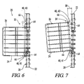
FIG. 6 is a top view of an embodiment of a material collection device shown with a conveyor support substantially flush with the guide. -
FIG. 7 is a top view of an embodiment of a material collection device shown with a conveyor support in a second position which includes one side spaced from the guide. - Referring generally now to
FIGS. 1-7 , a road processing machine is schematically shown and generally designated by thenumeral 10. The road processing machine (10) generally includes a processing device (12), which can also be described as a milling drum (12), for processing the surface (14) which can be described as a road (14). The road processing machine (10) also includes at least one stanchion (16) used to support a conveyor (18) to transfer the pieces of the surface (14) as the processing device (12) mills pieces of the surface (14). - The shiftable material collection device (20), which can also be described as a shiftable material removal device (20), is a novel invention for a road processing machine (10). The material collection device (20) comprises a guide (22) and a conveyor support (24). The guide (22) includes a material discard opening (26) and an attachment face (28). The conveyor support (24) is shiftably fixed to the guide (22) and is positionable in a substantially horizontal plane with respect to the attachment face (28).
- Additionally, the guide (22) is positioned to direct particles (30) from the road (14) through the material discard opening (26) to the conveyor support (24) and conveyor (18).
- As seen in
FIGS. 1 and 2 , the conveyor support (24) is movable between a first position (32) wherein the conveyor support (24) is substantially parallel to the guide (22) and a second position (34) where the conveyor support (24) is substantially oblique to the guide (22). The movement between the first position (32) and second position (34) can be described as a planar positioning of the conveyor support (24) with respect to the guide (22). - In the first position, the conveyor support (24) is substantially flush to the guide (22) while in the second position at least one side (36) of the conveyor support (22) is spaced from the guide (32). Additionally, the first position (22) is substantially horizontally adjacent to the second position (34). When in a second position (34), the conveyor support (24) creates an angle (38) with respect to the attachment face (28) of the guide (22). The angle (38) is preferably approximately five degrees.
- In a preferred embodiment, the attachment between the conveyor support (24) and the guide (22) is shiftably fixed by at least one armature (40). A most preferred embodiment includes a first armature (41) and a second armature (43) shiftably fixing the conveyor support (24) to the guide (22). The armatures (40) include four rotatively linked elements positioned to allow a shiftable attachment between the conveyor support (24) and the guide (22). Each armature (40), which can be described as rotational attachments (40), includes a first rotational axis (64) and second rotational axis (66) positioned to shift the conveyor support (24) in a substantially horizontal plane between a first position (32) substantially parallel to the guide (22) and a second position (34) oblique to the guide. Each armature (40) can rotate independently about either rotational axis (64 and 66).
- The interaction between the first armature (41), the second armature (43), the conveyor support (24) and the guide (22) can be described as a four bar linkage. Additionally, the first armature (41) extends from the guide (22) a first distance (42) while the second armature (43) extends from the guide (22) a second distance (44). Preferably, the second distance (44) is longer than the first distance of (42), which can facilitate a proper positioning of the conveyor support (24).
- As seen in
FIGS. 1 and 2 , the guide (22) can also include stops (46) positioned on the guide (22) to engage the armatures (40) when the conveyor support (24) is in the first and second positions (32 and 34). The stops (46) can also facilitate a proper positioning of the conveyor support (24). - The conveyor support (24) is positioned to accept particles (30) from a larger processing device (48), or milling device (48), when in the first position (32) and is positioned to accept particles (30) from a smaller processing device (50), or smaller milling device (50), when in the second position (34). These larger and smaller processing devices (48 and 50) are schematically represented in
FIGS. 4 and 5 and can vary in widths as dictated by the specific application and size of the road processing machine (10). - The material removal device (20) also comprises a conveying system (52). The conveying system (52) includes the conveyor (18), the stanchion (16), a first end (54) and a second end (56). The first end (54) is supported by the conveyor support (24) while the stanchion (16) supports the second end (56). The second end (56) is supported by the stanchion (16) and movable in a substantially horizontal plane from a third position (58) to a fourth position (60). The second end (56) is preferably not fixed to stanchions (16), but can slide freely on the support (17) attached to the stanchions (16). The third and fourth positions (58 and 60) preferably maintain the second end (56) between the plurality of stanchions (16) in order to properly discard the particles (30) milled from the road (14).
- The guide (22) further includes a removable plate (62), which can also be described as a removable section (62), positioned on the guide (22) to expand the size of the material discard opening (26). Preferably the removable section (62) is positioned proximate to the second position (34) of the conveyor support (24). Additionally, the removable section (62) is positioned to expand the size of the material discard opening (26) as the size of the processing device (12) is reduced. When both armatures (41 and 43) are used, the removable panel (62) is positioned proximate to the second armature (43).
- In a preferred embodiment the conveyor support (24) includes a cradle-like shape to support the conveyor (18) in order to properly collect and transport particles (30) away from the milling device (12).
Claims (16)
- A road milling machine (10), comprising
a collection device (20) for collecting the material cut from the surface by a milling drum (12), the collection device comprising:a guide (22) including a material discard opening (26) and an attachment face (28);a conveyor support (24) linked to the guide (22)wherein the guide (22) is suitable to be positioned to direct milled particles (30) from the road through the material discard opening (26) to the conveyor support (24); characterized in that,the conveyor support (24) is fixed to the guide (22) by at least one four bar linkage, such that the conveyer support (24) is shiftable in a substantially horizontal plane with respect to the attachment face (28) of the guide (22), wherein the guide (22) further includes a removable section (62) positioned to expand the size of the material discard opening (26). - The road milling machine of claim 1, wherein the four bar linkage comprises the guide (22), the conveyor support (24), a first armature (41), and a second armature (43).
- The road milling machine of claim 2, wherein each armature (41, 43) is independently rotatable.
- The road milling machine of claim 3, wherein the first armature (41) extends from the guide (22) a first distance and the second armature (43) extends from the guide a second distance, the second distance being longer than the first distance.
- The road milling machine of one of the claims 1 to 4, wherein the conveyor support (24) is horizontally moveable between a first position (32) wherein the conveyor support (24) is substantially parallel to the guide (22) and a second position (34) wherein the conveyor support (24) is substantially oblique to the guide (22).
- The road milling machine of claim 5, wherein the conveyor support (24) is substantially flush to the guide (22) in the first position (32) and includes at least one side spaced from the guide (22) in the second position (34).
- The road milling machine of one of the claims 1 to 6, wherein the removable section (62) is positioned proximate to the second position (34) of the conveyor support (24).
- The road milling machine of one of the claims 1 to 7, wherein the removable section (62) is positioned to expand the size of the material discard opening (26) as the size of the milling drum (12) is reduced.
- The road milling machine of one of the claims 5 to 8, wherein the conveyor support (24) is positioned to accept particles (30) from a larger milling drum (12) in the first position (32) and particles (30) from a smaller milling drum (12) in the second position (34).
- The road milling machine of one of claims 1 to 9, further comprising a conveying system (18) having a first end (54) and a second end (56), the first end supported by the conveyor support (24).
- The road milling machine of claim 10, wherein the conveying system (18) further includes a plurality of stanchions (16) operatively supporting the second end (56).
- The road milling machine of claim 10, wherein the second end is supported by the plurality of stanchions (16) and moveable in a second substantially horizontal plane from a third position (58) to a fourth position (60).
- The road milling machine of claim 12, wherein the third and fourth positions (58, 60) maintain the second end (56) substantially between the plurality of stanchions (16).
- The road milling machine of one of the claims 2 to 13, wherein the removable section (62) is a panel positioned proximate the second armature (43).
- The road milling machine of one of the claims 5 to 14, wherein the conveyor support (24) intersects the guide (22) at an angle of approximately five degrees in the second position (34).
- The road milling machine of one of the claims 5 to 15, wherein the second position (34) is substantially horizontally adjacent to the first position (32).
Applications Claiming Priority (2)
| Application Number | Priority Date | Filing Date | Title |
|---|---|---|---|
| US10/948,593 US7131704B2 (en) | 2004-09-23 | 2004-09-23 | Shiftable conveyor for road milling machine |
| PCT/US2005/034314 WO2006034481A1 (en) | 2004-09-23 | 2005-09-23 | Shiftable conveyor for road milling machine |
Publications (3)
| Publication Number | Publication Date |
|---|---|
| EP1812684A1 EP1812684A1 (en) | 2007-08-01 |
| EP1812684A4 EP1812684A4 (en) | 2013-01-02 |
| EP1812684B1 true EP1812684B1 (en) | 2015-04-15 |
Family
ID=36073210
Family Applications (1)
| Application Number | Title | Priority Date | Filing Date |
|---|---|---|---|
| EP05801231.1A Expired - Lifetime EP1812684B1 (en) | 2004-09-23 | 2005-09-23 | Road milling machine with shiftable conveyor |
Country Status (3)
| Country | Link |
|---|---|
| US (1) | US7131704B2 (en) |
| EP (1) | EP1812684B1 (en) |
| WO (1) | WO2006034481A1 (en) |
Families Citing this family (9)
| Publication number | Priority date | Publication date | Assignee | Title |
|---|---|---|---|---|
| US7891479B2 (en) * | 2007-09-07 | 2011-02-22 | Carl Evangelista | Modular conveyor system |
| CA2614538C (en) * | 2007-12-10 | 2011-03-29 | Triple Star Manufacturing Ltd. | Steerable wheel for an agricultural conveyor |
| FR2953535A1 (en) * | 2009-12-03 | 2011-06-10 | Lomaroute Sa | Self-propelled public work vehicle for tillage of tarred road surface, has suspension units suspending conveyor to chassis to retract lower end of conveyor under effect of milling products striking lower end to increase inter-space |
| US20110148187A1 (en) * | 2009-12-18 | 2011-06-23 | Scott Francis Lyons | Replaceable Track Pad and Mounting Plate |
| US9328468B2 (en) | 2012-03-08 | 2016-05-03 | Wirtgen Gmbh | Self-propelled road milling machine with adjustable width scraper blade |
| DE102012203649A1 (en) | 2012-03-08 | 2013-09-12 | Wirtgen Gmbh | Self-propelled road milling machine for working on road surfaces, in particular large milling machine |
| DE102015209740A1 (en) | 2014-12-30 | 2016-06-30 | Wirtgen Gmbh | Self-propelled road milling machine for working on road surfaces, as well as methods for working on road surfaces with a road milling machine |
| DE102017000212A1 (en) | 2017-01-13 | 2018-07-19 | Dynapac Gmbh | Road construction machine and method for operating a road construction machine |
| DE102021114706A1 (en) * | 2021-06-08 | 2022-12-08 | Wirtgen Gmbh | Self-propelled milling machine with a machine frame and a conveyor for discharging material |
Family Cites Families (20)
| Publication number | Priority date | Publication date | Assignee | Title |
|---|---|---|---|---|
| US2350579A (en) * | 1942-09-25 | 1944-06-06 | Bingham Charles Russell | Vehicle hitch |
| US3281162A (en) * | 1964-06-25 | 1966-10-25 | Raymond M Carson | Wide range tow bar |
| DE3145713A1 (en) | 1981-11-19 | 1983-05-26 | Marks GmbH, 4353 Oer-Erkenschwick | Cutting roller |
| US4560207A (en) * | 1984-03-01 | 1985-12-24 | Caterpillar Tractor Co. | Method and apparatus for fragmenting asphalt |
| US4720045A (en) * | 1985-04-23 | 1988-01-19 | Nelson Irrigation Corporation | Large volume sprinkler head with part-circle step by step movements in both directions |
| US4704045A (en) | 1985-10-11 | 1987-11-03 | Taylor Thomas M | Apparatus and method for pulverizing asphalt |
| US4720207A (en) * | 1986-08-29 | 1988-01-19 | Koehring Company | Segmented rotor |
| US4834463A (en) | 1988-05-23 | 1989-05-30 | Nye Edward L | Pavement planer |
| DE4037448B4 (en) | 1990-11-24 | 2005-09-29 | Wirtgen Gmbh | Milling device for road milling machines |
| US5219450A (en) * | 1991-01-28 | 1993-06-15 | Thurk John H | Mobile asphalt mix plant with component sensing and distinct steering means |
| US5178253A (en) * | 1991-08-26 | 1993-01-12 | Ingersoll-Rand Company | Swing mechanism for a vehicular conveyor |
| US5441361A (en) * | 1993-12-17 | 1995-08-15 | Astec Industries, Inc. | Field convertible apparatus for conducting either front load road planing operation or cold in-place recycling operation |
| US5474397A (en) * | 1994-05-31 | 1995-12-12 | Ingersoll-Rand Company | Drum access mechanism |
| US5505598A (en) * | 1994-07-29 | 1996-04-09 | Wirtgen America, Inc. | Milling machine with multi-width cutter |
| US5582490A (en) * | 1994-09-22 | 1996-12-10 | Wirtgen America, Inc. | Rumble strip cutter wheel |
| DE19726122C2 (en) * | 1997-06-20 | 2002-03-07 | Wirtgen Gmbh | Device for milling off floor coverings, in particular roadways |
| DE19814053B4 (en) * | 1998-03-30 | 2007-07-26 | Wirtgen Gmbh | Apparatus for milling off floor surfaces, in particular roadways |
| US6386352B1 (en) * | 2001-04-30 | 2002-05-14 | Blaw-Knox Construction Equipment Corporation | Swing conveyor assembly |
| US6733086B1 (en) * | 2002-03-15 | 2004-05-11 | Ri Properties, Inc. | Vacuum system for milling machine |
| DE10247579B3 (en) * | 2002-10-11 | 2004-04-15 | Wirtgen Gmbh | Scraper device for milling drums of a construction machine, as well as method |
-
2004
- 2004-09-23 US US10/948,593 patent/US7131704B2/en not_active Expired - Lifetime
-
2005
- 2005-09-23 EP EP05801231.1A patent/EP1812684B1/en not_active Expired - Lifetime
- 2005-09-23 WO PCT/US2005/034314 patent/WO2006034481A1/en not_active Ceased
Also Published As
| Publication number | Publication date |
|---|---|
| US7131704B2 (en) | 2006-11-07 |
| WO2006034481A1 (en) | 2006-03-30 |
| US20060061204A1 (en) | 2006-03-23 |
| EP1812684A4 (en) | 2013-01-02 |
| EP1812684A1 (en) | 2007-08-01 |
Similar Documents
| Publication | Publication Date | Title |
|---|---|---|
| US7131704B2 (en) | Shiftable conveyor for road milling machine | |
| US6877502B2 (en) | Multi-blade concrete cutting saw | |
| US6296318B1 (en) | Device for milling off ground surfaces especially roadways | |
| AU2024205617B2 (en) | Flow divider for a spinner spreader | |
| US20030075628A1 (en) | Crusher apparatus | |
| JP2002510000A (en) | Grinding equipment for ground surfaces, especially roadways | |
| DE10036426A1 (en) | Dust collection system has driven member rotatably mounted on member, which is movable relative to recessed member between two positions and has enclosed pathway with inlet, to which collector is disposed at, with portion in recess | |
| RU2466833C2 (en) | System of drum shears | |
| KR102162523B1 (en) | Aggregate transport device that combines the function of dispersing and crushing aggregates | |
| CN210411100U (en) | Defective board crusher | |
| EP2200791A1 (en) | Depositing/transporting-away device for cut foodstuff and food cutting machine | |
| CN112108247A (en) | Construction waste recycled aggregate treatment process and device | |
| WO2007072464A3 (en) | Machine for optimized cutting of slabs in stone or lithoid material | |
| EP0560222B1 (en) | Plant for screening and mixing soil, gravel, sand, etc. | |
| EP1125679A2 (en) | Apparatus for disposing of cut green body pieces of an insulator preform | |
| CN117621214A (en) | High-strength environmentally friendly fiberboard based on camphor wood construction waste and its processing technology | |
| KR200176534Y1 (en) | A removal device of the knob of fruit container | |
| CZ66594A3 (en) | Device for liquidating old glazed windows | |
| CN219234133U (en) | Aluminium bar cutting equipment | |
| JP2667618B2 (en) | Plate material sorting equipment | |
| CN220720416U (en) | Paper collection, waste collection and protection integrated device | |
| KR200164873Y1 (en) | Steel transportation conveyer of cutting steel | |
| JP2015517920A (en) | Cutting device for printing substrate | |
| JPH0639624A (en) | Width cutting device for flat deck plate | |
| CN213468083U (en) | Online crushing and agitating unit of filter-pressing coal slime |
Legal Events
| Date | Code | Title | Description |
|---|---|---|---|
| PUAI | Public reference made under article 153(3) epc to a published international application that has entered the european phase |
Free format text: ORIGINAL CODE: 0009012 |
|
| 17P | Request for examination filed |
Effective date: 20070201 |
|
| AK | Designated contracting states |
Kind code of ref document: A1 Designated state(s): AT BE BG CH CY CZ DE DK EE ES FI FR GB GR HU IE IS IT LI LT LU LV MC NL PL PT RO SE SI SK TR |
|
| DAX | Request for extension of the european patent (deleted) | ||
| REG | Reference to a national code |
Ref country code: DE Ref legal event code: R079 Ref document number: 602005046351 Country of ref document: DE Free format text: PREVIOUS MAIN CLASS: E21C0025000000 Ipc: E01C0023088000 |
|
| A4 | Supplementary search report drawn up and despatched |
Effective date: 20121203 |
|
| RIC1 | Information provided on ipc code assigned before grant |
Ipc: E01C 23/088 20060101AFI20121127BHEP |
|
| 17Q | First examination report despatched |
Effective date: 20130830 |
|
| GRAP | Despatch of communication of intention to grant a patent |
Free format text: ORIGINAL CODE: EPIDOSNIGR1 |
|
| INTG | Intention to grant announced |
Effective date: 20141024 |
|
| GRAS | Grant fee paid |
Free format text: ORIGINAL CODE: EPIDOSNIGR3 |
|
| GRAA | (expected) grant |
Free format text: ORIGINAL CODE: 0009210 |
|
| AK | Designated contracting states |
Kind code of ref document: B1 Designated state(s): AT BE BG CH CY CZ DE DK EE ES FI FR GB GR HU IE IS IT LI LT LU LV MC NL PL PT RO SE SI SK TR |
|
| REG | Reference to a national code |
Ref country code: GB Ref legal event code: FG4D Ref country code: CH Ref legal event code: EP |
|
| REG | Reference to a national code |
Ref country code: IE Ref legal event code: FG4D |
|
| REG | Reference to a national code |
Ref country code: AT Ref legal event code: REF Ref document number: 722064 Country of ref document: AT Kind code of ref document: T Effective date: 20150515 |
|
| REG | Reference to a national code |
Ref country code: DE Ref legal event code: R096 Ref document number: 602005046351 Country of ref document: DE Effective date: 20150528 |
|
| REG | Reference to a national code |
Ref country code: NL Ref legal event code: VDEP Effective date: 20150415 |
|
| REG | Reference to a national code |
Ref country code: AT Ref legal event code: MK05 Ref document number: 722064 Country of ref document: AT Kind code of ref document: T Effective date: 20150415 |
|
| REG | Reference to a national code |
Ref country code: FR Ref legal event code: PLFP Year of fee payment: 11 |
|
| REG | Reference to a national code |
Ref country code: LT Ref legal event code: MG4D |
|
| PG25 | Lapsed in a contracting state [announced via postgrant information from national office to epo] |
Ref country code: NL Free format text: LAPSE BECAUSE OF FAILURE TO SUBMIT A TRANSLATION OF THE DESCRIPTION OR TO PAY THE FEE WITHIN THE PRESCRIBED TIME-LIMIT Effective date: 20150415 |
|
| PG25 | Lapsed in a contracting state [announced via postgrant information from national office to epo] |
Ref country code: ES Free format text: LAPSE BECAUSE OF FAILURE TO SUBMIT A TRANSLATION OF THE DESCRIPTION OR TO PAY THE FEE WITHIN THE PRESCRIBED TIME-LIMIT Effective date: 20150415 Ref country code: FI Free format text: LAPSE BECAUSE OF FAILURE TO SUBMIT A TRANSLATION OF THE DESCRIPTION OR TO PAY THE FEE WITHIN THE PRESCRIBED TIME-LIMIT Effective date: 20150415 Ref country code: LT Free format text: LAPSE BECAUSE OF FAILURE TO SUBMIT A TRANSLATION OF THE DESCRIPTION OR TO PAY THE FEE WITHIN THE PRESCRIBED TIME-LIMIT Effective date: 20150415 Ref country code: PT Free format text: LAPSE BECAUSE OF FAILURE TO SUBMIT A TRANSLATION OF THE DESCRIPTION OR TO PAY THE FEE WITHIN THE PRESCRIBED TIME-LIMIT Effective date: 20150817 |
|
| PG25 | Lapsed in a contracting state [announced via postgrant information from national office to epo] |
Ref country code: AT Free format text: LAPSE BECAUSE OF FAILURE TO SUBMIT A TRANSLATION OF THE DESCRIPTION OR TO PAY THE FEE WITHIN THE PRESCRIBED TIME-LIMIT Effective date: 20150415 Ref country code: LV Free format text: LAPSE BECAUSE OF FAILURE TO SUBMIT A TRANSLATION OF THE DESCRIPTION OR TO PAY THE FEE WITHIN THE PRESCRIBED TIME-LIMIT Effective date: 20150415 Ref country code: IS Free format text: LAPSE BECAUSE OF FAILURE TO SUBMIT A TRANSLATION OF THE DESCRIPTION OR TO PAY THE FEE WITHIN THE PRESCRIBED TIME-LIMIT Effective date: 20150815 Ref country code: GR Free format text: LAPSE BECAUSE OF FAILURE TO SUBMIT A TRANSLATION OF THE DESCRIPTION OR TO PAY THE FEE WITHIN THE PRESCRIBED TIME-LIMIT Effective date: 20150716 |
|
| REG | Reference to a national code |
Ref country code: DE Ref legal event code: R026 Ref document number: 602005046351 Country of ref document: DE |
|
| PLBI | Opposition filed |
Free format text: ORIGINAL CODE: 0009260 |
|
| PG25 | Lapsed in a contracting state [announced via postgrant information from national office to epo] |
Ref country code: DK Free format text: LAPSE BECAUSE OF FAILURE TO SUBMIT A TRANSLATION OF THE DESCRIPTION OR TO PAY THE FEE WITHIN THE PRESCRIBED TIME-LIMIT Effective date: 20150415 Ref country code: EE Free format text: LAPSE BECAUSE OF FAILURE TO SUBMIT A TRANSLATION OF THE DESCRIPTION OR TO PAY THE FEE WITHIN THE PRESCRIBED TIME-LIMIT Effective date: 20150415 |
|
| 26 | Opposition filed |
Opponent name: CATERPILLAR INC. Effective date: 20151229 |
|
| PLAX | Notice of opposition and request to file observation + time limit sent |
Free format text: ORIGINAL CODE: EPIDOSNOBS2 |
|
| PG25 | Lapsed in a contracting state [announced via postgrant information from national office to epo] |
Ref country code: CZ Free format text: LAPSE BECAUSE OF FAILURE TO SUBMIT A TRANSLATION OF THE DESCRIPTION OR TO PAY THE FEE WITHIN THE PRESCRIBED TIME-LIMIT Effective date: 20150415 Ref country code: PL Free format text: LAPSE BECAUSE OF FAILURE TO SUBMIT A TRANSLATION OF THE DESCRIPTION OR TO PAY THE FEE WITHIN THE PRESCRIBED TIME-LIMIT Effective date: 20150415 Ref country code: RO Free format text: LAPSE BECAUSE OF NON-PAYMENT OF DUE FEES Effective date: 20150415 Ref country code: SK Free format text: LAPSE BECAUSE OF FAILURE TO SUBMIT A TRANSLATION OF THE DESCRIPTION OR TO PAY THE FEE WITHIN THE PRESCRIBED TIME-LIMIT Effective date: 20150415 |
|
| PG25 | Lapsed in a contracting state [announced via postgrant information from national office to epo] |
Ref country code: MC Free format text: LAPSE BECAUSE OF FAILURE TO SUBMIT A TRANSLATION OF THE DESCRIPTION OR TO PAY THE FEE WITHIN THE PRESCRIBED TIME-LIMIT Effective date: 20150415 Ref country code: LU Free format text: LAPSE BECAUSE OF FAILURE TO SUBMIT A TRANSLATION OF THE DESCRIPTION OR TO PAY THE FEE WITHIN THE PRESCRIBED TIME-LIMIT Effective date: 20150923 Ref country code: IT Free format text: LAPSE BECAUSE OF FAILURE TO SUBMIT A TRANSLATION OF THE DESCRIPTION OR TO PAY THE FEE WITHIN THE PRESCRIBED TIME-LIMIT Effective date: 20150415 |
|
| REG | Reference to a national code |
Ref country code: CH Ref legal event code: PL |
|
| PG25 | Lapsed in a contracting state [announced via postgrant information from national office to epo] |
Ref country code: SI Free format text: LAPSE BECAUSE OF FAILURE TO SUBMIT A TRANSLATION OF THE DESCRIPTION OR TO PAY THE FEE WITHIN THE PRESCRIBED TIME-LIMIT Effective date: 20150415 |
|
| REG | Reference to a national code |
Ref country code: IE Ref legal event code: MM4A |
|
| PLBB | Reply of patent proprietor to notice(s) of opposition received |
Free format text: ORIGINAL CODE: EPIDOSNOBS3 |
|
| PG25 | Lapsed in a contracting state [announced via postgrant information from national office to epo] |
Ref country code: CH Free format text: LAPSE BECAUSE OF NON-PAYMENT OF DUE FEES Effective date: 20150930 Ref country code: LI Free format text: LAPSE BECAUSE OF NON-PAYMENT OF DUE FEES Effective date: 20150930 Ref country code: IE Free format text: LAPSE BECAUSE OF NON-PAYMENT OF DUE FEES Effective date: 20150923 |
|
| PG25 | Lapsed in a contracting state [announced via postgrant information from national office to epo] |
Ref country code: BE Free format text: LAPSE BECAUSE OF FAILURE TO SUBMIT A TRANSLATION OF THE DESCRIPTION OR TO PAY THE FEE WITHIN THE PRESCRIBED TIME-LIMIT Effective date: 20150415 |
|
| REG | Reference to a national code |
Ref country code: FR Ref legal event code: PLFP Year of fee payment: 12 |
|
| REG | Reference to a national code |
Ref country code: DE Ref legal event code: R100 Ref document number: 602005046351 Country of ref document: DE |
|
| PLCK | Communication despatched that opposition was rejected |
Free format text: ORIGINAL CODE: EPIDOSNREJ1 |
|
| STAA | Information on the status of an ep patent application or granted ep patent |
Free format text: STATUS: THE PATENT HAS BEEN GRANTED |
|
| PG25 | Lapsed in a contracting state [announced via postgrant information from national office to epo] |
Ref country code: BG Free format text: LAPSE BECAUSE OF FAILURE TO SUBMIT A TRANSLATION OF THE DESCRIPTION OR TO PAY THE FEE WITHIN THE PRESCRIBED TIME-LIMIT Effective date: 20150415 Ref country code: HU Free format text: LAPSE BECAUSE OF FAILURE TO SUBMIT A TRANSLATION OF THE DESCRIPTION OR TO PAY THE FEE WITHIN THE PRESCRIBED TIME-LIMIT; INVALID AB INITIO Effective date: 20050923 |
|
| PG25 | Lapsed in a contracting state [announced via postgrant information from national office to epo] |
Ref country code: CY Free format text: LAPSE BECAUSE OF FAILURE TO SUBMIT A TRANSLATION OF THE DESCRIPTION OR TO PAY THE FEE WITHIN THE PRESCRIBED TIME-LIMIT Effective date: 20150415 Ref country code: SE Free format text: LAPSE BECAUSE OF FAILURE TO SUBMIT A TRANSLATION OF THE DESCRIPTION OR TO PAY THE FEE WITHIN THE PRESCRIBED TIME-LIMIT Effective date: 20150415 |
|
| PG25 | Lapsed in a contracting state [announced via postgrant information from national office to epo] |
Ref country code: TR Free format text: LAPSE BECAUSE OF FAILURE TO SUBMIT A TRANSLATION OF THE DESCRIPTION OR TO PAY THE FEE WITHIN THE PRESCRIBED TIME-LIMIT Effective date: 20150415 |
|
| PLBN | Opposition rejected |
Free format text: ORIGINAL CODE: 0009273 |
|
| STAA | Information on the status of an ep patent application or granted ep patent |
Free format text: STATUS: OPPOSITION REJECTED |
|
| REG | Reference to a national code |
Ref country code: FR Ref legal event code: PLFP Year of fee payment: 13 |
|
| 27O | Opposition rejected |
Effective date: 20170512 |
|
| REG | Reference to a national code |
Ref country code: FR Ref legal event code: PLFP Year of fee payment: 14 |
|
| PGFP | Annual fee paid to national office [announced via postgrant information from national office to epo] |
Ref country code: FR Payment date: 20190923 Year of fee payment: 15 |
|
| PGFP | Annual fee paid to national office [announced via postgrant information from national office to epo] |
Ref country code: GB Payment date: 20190924 Year of fee payment: 15 |
|
| PGFP | Annual fee paid to national office [announced via postgrant information from national office to epo] |
Ref country code: DE Payment date: 20190927 Year of fee payment: 15 |
|
| REG | Reference to a national code |
Ref country code: DE Ref legal event code: R119 Ref document number: 602005046351 Country of ref document: DE |
|
| GBPC | Gb: european patent ceased through non-payment of renewal fee |
Effective date: 20200923 |
|
| PG25 | Lapsed in a contracting state [announced via postgrant information from national office to epo] |
Ref country code: FR Free format text: LAPSE BECAUSE OF NON-PAYMENT OF DUE FEES Effective date: 20200930 Ref country code: DE Free format text: LAPSE BECAUSE OF NON-PAYMENT OF DUE FEES Effective date: 20210401 |
|
| PG25 | Lapsed in a contracting state [announced via postgrant information from national office to epo] |
Ref country code: GB Free format text: LAPSE BECAUSE OF NON-PAYMENT OF DUE FEES Effective date: 20200923 |