EP1812228B1 - Improvements in or relating to pour spout devices - Google Patents
Improvements in or relating to pour spout devices Download PDFInfo
- Publication number
- EP1812228B1 EP1812228B1 EP05810715A EP05810715A EP1812228B1 EP 1812228 B1 EP1812228 B1 EP 1812228B1 EP 05810715 A EP05810715 A EP 05810715A EP 05810715 A EP05810715 A EP 05810715A EP 1812228 B1 EP1812228 B1 EP 1812228B1
- Authority
- EP
- European Patent Office
- Prior art keywords
- pour spout
- cover
- flange
- wall
- container
- Prior art date
- Legal status (The legal status is an assumption and is not a legal conclusion. Google has not performed a legal analysis and makes no representation as to the accuracy of the status listed.)
- Expired - Lifetime
Links
Images


Classifications
-
- B—PERFORMING OPERATIONS; TRANSPORTING
- B31—MAKING ARTICLES OF PAPER, CARDBOARD OR MATERIAL WORKED IN A MANNER ANALOGOUS TO PAPER; WORKING PAPER, CARDBOARD OR MATERIAL WORKED IN A MANNER ANALOGOUS TO PAPER
- B31B—MAKING CONTAINERS OF PAPER, CARDBOARD OR MATERIAL WORKED IN A MANNER ANALOGOUS TO PAPER
- B31B50/00—Making rigid or semi-rigid containers, e.g. boxes or cartons
- B31B50/74—Auxiliary operations
- B31B50/81—Forming or attaching accessories, e.g. opening devices, closures or tear strings
- B31B50/84—Forming or attaching means for filling or dispensing contents, e.g. valves or spouts
-
- B—PERFORMING OPERATIONS; TRANSPORTING
- B65—CONVEYING; PACKING; STORING; HANDLING THIN OR FILAMENTARY MATERIAL
- B65D—CONTAINERS FOR STORAGE OR TRANSPORT OF ARTICLES OR MATERIALS, e.g. BAGS, BARRELS, BOTTLES, BOXES, CANS, CARTONS, CRATES, DRUMS, JARS, TANKS, HOPPERS, FORWARDING CONTAINERS; ACCESSORIES, CLOSURES, OR FITTINGS THEREFOR; PACKAGING ELEMENTS; PACKAGES
- B65D5/00—Rigid or semi-rigid containers of polygonal cross-section, e.g. boxes, cartons or trays, formed by folding or erecting one or more blanks made of paper
- B65D5/42—Details of containers or of foldable or erectable container blanks
- B65D5/72—Contents-dispensing means
- B65D5/74—Spouts
- B65D5/746—Spouts formed separately from the container
-
- B—PERFORMING OPERATIONS; TRANSPORTING
- B65—CONVEYING; PACKING; STORING; HANDLING THIN OR FILAMENTARY MATERIAL
- B65D—CONTAINERS FOR STORAGE OR TRANSPORT OF ARTICLES OR MATERIALS, e.g. BAGS, BARRELS, BOTTLES, BOXES, CANS, CARTONS, CRATES, DRUMS, JARS, TANKS, HOPPERS, FORWARDING CONTAINERS; ACCESSORIES, CLOSURES, OR FITTINGS THEREFOR; PACKAGING ELEMENTS; PACKAGES
- B65D2251/00—Details relating to container closures
- B65D2251/02—Grip means
-
- B—PERFORMING OPERATIONS; TRANSPORTING
- B65—CONVEYING; PACKING; STORING; HANDLING THIN OR FILAMENTARY MATERIAL
- B65D—CONTAINERS FOR STORAGE OR TRANSPORT OF ARTICLES OR MATERIALS, e.g. BAGS, BARRELS, BOTTLES, BOXES, CANS, CARTONS, CRATES, DRUMS, JARS, TANKS, HOPPERS, FORWARDING CONTAINERS; ACCESSORIES, CLOSURES, OR FITTINGS THEREFOR; PACKAGING ELEMENTS; PACKAGES
- B65D2401/00—Tamper-indicating means
- B65D2401/15—Tearable part of the closure
Definitions
- This invention relates to a method of applying a pour spout device to a container and also relates to a package comprising a pour spout device .
- US-A-5,108,029 discloses a reclosable, one piece, pour spout device for attaching to a container, the device including a pour spout comprised of a flange and a pour spout body which consists of a cylindrical extension which extends upwards from the flange and a cylindrical stem which extends downwards from the flange.
- a cap-form cover is hingedly connected to the flange and is adapted to be engaged with and disengaged from the cylindrical extension in order to prevent or permit discharge of the contents from the container.
- the device has a tamper-evident feature which may be in the form of a pair of footless legs which are formed integrally with the cover and subsequently have their free ends bead-welded to the upper surface of the flange.
- GB-A-2,301,098 discloses a tamper-evident, thermoplastics, pour spout device having a spout and a plug-form cover attached to a plastics or plastics-coated container.
- the fitment and the cover are moulded simultaneously with a substantial space between them and with an elongate runner connecting them.
- the runner comprises a tear tab which slides through an apertured space on the cover.
- the device has a flange which may be welded or otherwise secured to the container.
- the tab may be pulled by the consumer to open the container.
- the cover may be unscrewed from the spout or otherwise disengaged.
- the inner end of the spout has integrally formed therewith a sealing ring which slants downwardly and inwardly to engage a smooth surface on the exterior of a skirt of the cover, the primary liquid-tight seal of the device being preferably the sealing effect between that ring and that smooth surface.
- US-A-5,799,840 discloses a closure for a container wherein the closure has a spout with flange, a cap and a link connecting the spout and the cap.
- the link has a joint at its connection to the spout which allows for the folding of a portion of the link toward the flange for binding thereto.
- the link portion may be folded into a cutout on the flange.
- a method of securing the closure to a container includes bonding the link portion to the flange simultaneously with the binding of the closure to a thermoplastic surface of a container using an energy emission process such as ultrasonic sealing.
- the closure may also have a tamper evident structure attached thereon to provide a visual indication that the closure has been opened.
- That structure includes an L-shaped leg secured to the cap at a tear joint that, for example, includes one or more notches.
- a gripping arm extends from the main part of the leg.
- the flange includes a cutout that is dimensioned to accommodate the foot therein. The cutout may merely be a recess or may extend completely through the flange.
- WO-A-0 1/15979 discloses a closable opening device having a flanged frame which defines a pour opening and is fittable to a wall of a sealed package for a pourable food product and about a removable portion of the package; a screw cap co-operating with the frame to close the pour opening; and tamperproofing means connected to the cap by breakable connecting means and defining an inviolable closed position of the cap on the frame.
- the tamperproofing means comprises a block of plastics which is connected externally to the side of the cap by two thin, low-break-strength strips, engages a through hole formed in the flange, and is heat-sealed to the lateral edge of the hole and to a surface film of the wall of the package.
- the block is substantially in the form of a triangular prism and is connected integrally, by means of strips and along one of its lateral edges, to a projection projecting radially outwards from a portion of the cap.
- the cap is preferably pressed into the frame, after first aligning the block with the hole in the frame.
- CA-A-2,502,868 discloses a hatch-type pour spout device for a container of composite packaging material.
- the device comprises a pour spout and a flanged, tub-shaped cover moulded thereto via a hinge arrangement.
- the pour spout is fused or bonded to the outside of the container with the flat underside thereof and comprises a rounded enclosing projection extending upwards to form a pouring spout body
- the inner end of the projection is open.
- the tub-shaped portion of the cover projects upwards to present a planar upper surface and, in the closed state, is a positive fit in the pouring opening in the underside of the spout.
- That planar surface either is flush with the underside of the spout, or extends below the same by a maximum of 0.5mm., and is either bonded with the outside of a pre-punched zone of the composite packaging or fused to a sealing film of the composite packaging which is exposed due to punching.
- the cover also includes an external flange, and the hinge arrangement extends between that flange and an external flange of the spout.
- On both sides of the tub-shaped portion of the cover there are L-shaped tamper-evident wings moulded to the underside of the flange of the cover. The shorter parts of these wings are dimensioned in such a way that, when the cover is turned onto the spout, they fit into square indentations in the flange of the spout, with which they are fused after initial closing.
- WO-A-2004/058574 discloses an apparatus for use in welding a pour spout fitment to a container comprising an ultrasonic welding horn formed with a recess at one end for receiving part of the fitment, an anvil between an annular surface portion of which and that one end of the horn are vibratingly pressed a wall of the container and a flange of the fitment to weld the wall and the flange to each other, and a head fixed relative to and protruding from the anvil for receiving the fitment over a free end thereof, and a ring substantially co-axial with the head and protruding substantially radially outwards from the head at the opposite end of the head for maintaining an annular, radially inner portion of the flange spaced axially outwards from the annular surface portion of the anvil, the outer periphery of the ring being radially dimensioned to be received in the recess.
- a package comprising a container and a pour spout device attachingly applied to a wall of said container, said device comprising a pour spout, a tamper-evidence arrangement attached to said cover and to a flange of said pour spout extending outwards from a pour spout body and by way of which said pour spout is attached to said wall, said arrangement comprising tamper-evidence, footed legs whereof the feet are attached to said flange, characterized in that the feet of the legs are attached to, but not recessed into respective hollows in, an upper surface of said flange, and also characterized in that said device extends from inside to outside of said wall through a hole through said wall, with said cover being outside said wall, and said flange and each foot are attached to the inside surface of said wall around said hole.
- the tamper-evidence legs can be positioned at any appropriate locations at the periphery of the cover, for example at respective opposite sides of a front part of the cover and/or at the very front of that front part.
- the device may be applied to the outside surface of the wall of the container, around a pouring hole or potential site of a pouring hole through the wall, with the flange of the pour spout being sealed, preferably ultrasonically, round the hole or the potential site, and with the legs being sealed, preferably ultrasonically, to that flange.
- the device may be introduced into the container before filling and brought to protrude outwardly through a hole through the wall, with the flange of the pour spout being sealed, preferably ultrasonically, to the inside surface of the wall round the hole and with the legs being sealed, again preferably ultrasonically, between the flange and the inside surface of the wall.
- the cover comprises a ring-form skirt closely receivable in the pour spout body, the pour spout body including an inwardly protruding, ring-form, readily flexible, resilient lip defining the inflow mouth of the pour spout for sealingly bearing on the ring-form skirt; and the device has been moulded in one piece.
- the device may be hatch-form, with an arm projecting from and extending over an outer surface of the cover for use in opening the cover. It is thereby possible to facilitate opening of the cover, because the device presents to the consumer an arm which can be readily engageable for pulling open the cover.
- the pour spout device 2 takes the form of a fitment which in the condition shown in Figures 1 and 2 is for applying, as shown in Figure 7 , to a wall 4 of a packaging carton for a flowable substance, the wall 4 comprising a paperboard layer 4A coated at its inner and outer surfaces with thermoplastics layers 4B and 4C.
- the layers 4B and 4C may be of a moisture barrier plastics material, particularly low density polyethylene (LDPE), and there may be an oxygen barrier layer (not shown) of, for example, aluminium foil or ethylene vinyl alcohol (EVOH) between the layers 4A and 4B.
- the flowable substance contained may be a liquid, such as milk or fruit juice, or a powder, such as washing powder.
- the device 2 comprises a pour spout 6 and a cover 8 for closing the spout 6.
- the pour spout 6 includes a pour spout body 10 encircling a pouring outlet 12 and having an inflow mouth 14 and an outflow mouth 16.
- the body 10 is widened at its forward part so as to provide a widened pouring outlet 12.
- the pour spout 6 also includes a flange 18 which protrudes radially outwards from the body 10 and whereby the spout 6 is welded in a fluid-type manner to the layer 4B, the device 2 being of a thermoplastics material suitable for being ultrasonically welded to the layer 4B.
- the device 2 is moulded in one piece, with the connection between the spout 6 and the cover 8 being in the form of an integral hinge arrangement 20 close to the body 10, with a detent 22 included in the spout 6 being engageable in a slot 24 formed in the cover 8 to maintain the cover 8 releasably in its fully open position shown in Figures 1 and 2 .
- the cover 8 includes inner and outer, ring-form skirts 26 and 28 which extend substantially parallelly to each other.
- the skirt 26 is intended to engage sealingly inside the body 10 and for that purpose is formed with a ring-form rib 30 to engage sealingly beneath a ring-form rib 32 formed round the inside of the body 10.
- the body 10 may be formed with an inwardly protruding, ring-form, readily flexible, resilient lip 34 defining the inflow mouth 14 for sealingly bearing on the radially outer surface of the ring-form skirt 26.
- the ring-form skirt 28 which may be omitted, but which has the advantage of improving the stability of the device 2, sealingly engages the radially outer surface of the ring-form body 10. It will be appreciated that the co-operation between the skirt 26 and the lip 34, between the ribs 30 and 32, and between the body 10 and the skirt 28 provides a plurality of ring-form seals arranged in series with each other and thus providing fluid-tightness, even if one of the seals, owing to manufacturing tolerances, for example, is ineffective. Provision of a sealing lip, such as 34, on the inside of the body 10 as compared with the provision of such a lip on the outside of the skirt 26, has the advantage of simpler moulding thereof, particularly if the lip is provided at the level of the flange 18.
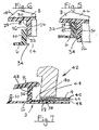
- the cover 8 is turned about the integral hinge arrangement 20 relative to the pour spout 6 so as to cause the body 10 to be received sealingly to the outside of the skirt 26, and sealingly to the inside of the skirt 28 if provided, as illustrated in Figure 5 .
- the device in the condition shown in Figures 3 to 5 is mounted upon an anvil (not shown) and is introduced into an as- yet-to-be-filled carton and caused to protrude through a pouring hole 40 formed through the wall 4, with the feet 38 extending to between the layer 4B and the flange 18.
- the feet 38 may be recessed into hollows (not shown) in the upper surface of the flange 18 such that, following welding, the lower surface of the layer 4B is flush with the upper surface of the flange 18 and, at the hollows, with the upper surfaces of the feet 38.
- the cover 8 After filling and top-closing and -sealing of the carton on the form-fill-seal machine, the package so formed is ultimately supplied to a consumer.
- the cover 8 At its corners adjacent to the legs 36, the cover 8 includes turned-up ears 46, whereby the consumer can insert a finger or thumbnail under each of the ears 46 in turn and press those corners upwards to break the tamper-evidence legs 36, so that the cover 8 can be turned backwards about the hinge arrangement 20 into the condition shown in Figures 1 and 2 , in which the detent 22 engages in the slot 24 to retain the cover 8 open relative to the spout 6.
- they may be formed at those locations with respective thinnings 48.
- the consumer With the cover 8 fully open, the consumer can empty at least part of the content of the package through the outlet 12.
- the front edge of the flange 18 is undercut, as indicated at 50.
- the package can be re-sealed by turning the cover 8 back into the condition shown in Figures 3 to 5 .
- each ear 46 is formed with respective upward and downward protrusions 52 and 54 therefrom in the form of angled ribs to facilitate gripping of the ear by the consumer.
- the cover 8 is formed with reinforcement in the form of ribs 55 extending from front to rear of the inner skirt 26.
- the body 10 has its upper part in the form of inner and outer skirts 10A and 10B, whereof the latter is discontinuous at the hinge 20.
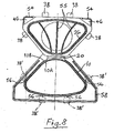
- the skirt 10B is formed at its outer peripheral surface with small protrusions 56 positioned such that, when the device is in its closed condition, the feet 38 are immediately outward thereof, as indicated in dot-dash lines at 38 in Figure 8 .
- those protrusions 56 obstruct inward movement of the legs 36 during the ultrasonic welding, they discourage undesired inward movement of the feet 38 during the welding.
- the flange 18 is formed with a reinforcing rib 58 around its outer edge zone.
- the cover 8 may be provided, at the front of its exterior, with a grippable tongue 60 shown in dot-dash lines and consisting of an upwardly extending part 60A and a substantially horizontal part 60B extending rearwardly over the outer surface of the cover 8.
- a grippable tongue 60 shown in dot-dash lines and consisting of an upwardly extending part 60A and a substantially horizontal part 60B extending rearwardly over the outer surface of the cover 8.
- the tongue 60 may be formed with a weakness 60C, in the form of a thinning serving to provide a hinge at the junction between the parts 60A and 60B.
Landscapes
- Engineering & Computer Science (AREA)
- Mechanical Engineering (AREA)
- Cartons (AREA)
- Closures For Containers (AREA)
- Lining Or Joining Of Plastics Or The Like (AREA)
- Bag Frames (AREA)
Abstract
Description
- This invention relates to a method of applying a pour spout device to a container and also relates to a package comprising a pour spout device .
-
US-A-5,108,029 discloses a reclosable, one piece, pour spout device for attaching to a container, the device including a pour spout comprised of a flange and a pour spout body which consists of a cylindrical extension which extends upwards from the flange and a cylindrical stem which extends downwards from the flange. A cap-form cover is hingedly connected to the flange and is adapted to be engaged with and disengaged from the cylindrical extension in order to prevent or permit discharge of the contents from the container. The device has a tamper-evident feature which may be in the form of a pair of footless legs which are formed integrally with the cover and subsequently have their free ends bead-welded to the upper surface of the flange. -
GB-A-2,301,098 -
US-A-5,799,840 discloses a closure for a container wherein the closure has a spout with flange, a cap and a link connecting the spout and the cap. The link has a joint at its connection to the spout which allows for the folding of a portion of the link toward the flange for binding thereto. The link portion may be folded into a cutout on the flange. A method of securing the closure to a container includes bonding the link portion to the flange simultaneously with the binding of the closure to a thermoplastic surface of a container using an energy emission process such as ultrasonic sealing. The closure may also have a tamper evident structure attached thereon to provide a visual indication that the closure has been opened. That structure includes an L-shaped leg secured to the cap at a tear joint that, for example, includes one or more notches. A gripping arm extends from the main part of the leg. The flange includes a cutout that is dimensioned to accommodate the foot therein. The cutout may merely be a recess or may extend completely through the flange. -
WO-A-0 1/15979 -
CA-A-2,502,868 discloses a hatch-type pour spout device for a container of composite packaging material. The device comprises a pour spout and a flanged, tub-shaped cover moulded thereto via a hinge arrangement. The pour spout is fused or bonded to the outside of the container with the flat underside thereof and comprises a rounded enclosing projection extending upwards to form a pouring spout body The inner end of the projection is open. In the opened state, the tub-shaped portion of the cover projects upwards to present a planar upper surface and, in the closed state, is a positive fit in the pouring opening in the underside of the spout. In the closed state, that planar surface either is flush with the underside of the spout, or extends below the same by a maximum of 0.5mm., and is either bonded with the outside of a pre-punched zone of the composite packaging or fused to a sealing film of the composite packaging which is exposed due to punching. The cover also includes an external flange, and the hinge arrangement extends between that flange and an external flange of the spout. On both sides of the tub-shaped portion of the cover there are L-shaped tamper-evident wings moulded to the underside of the flange of the cover. The shorter parts of these wings are dimensioned in such a way that, when the cover is turned onto the spout, they fit into square indentations in the flange of the spout, with which they are fused after initial closing. -
WO-A-2004/058574 discloses an apparatus for use in welding a pour spout fitment to a container comprising an ultrasonic welding horn formed with a recess at one end for receiving part of the fitment, an anvil between an annular surface portion of which and that one end of the horn are vibratingly pressed a wall of the container and a flange of the fitment to weld the wall and the flange to each other, and a head fixed relative to and protruding from the anvil for receiving the fitment over a free end thereof, and a ring substantially co-axial with the head and protruding substantially radially outwards from the head at the opposite end of the head for maintaining an annular, radially inner portion of the flange spaced axially outwards from the annular surface portion of the anvil, the outer periphery of the ring being radially dimensioned to be received in the recess. - According to one aspect of the present invention, there is provided a method comprising:-
- providing a pour spout device comprising a pour spout, a cover for closing said pour spout, and a tamper-evidence arrangement attached to said cover and comprising tamper-evidence, footed legs which are each in a condition with a proximal end attached to said cover and a distal end free,
- attachingly applying said device to said wall of said container, and
- attaching said arrangement to an external flange of a pour spout body of said pour spout,
- According to another aspect of the present invention, there is provided a package comprising a container and a pour spout device attachingly applied to a wall of said container, said device comprising a pour spout, a tamper-evidence arrangement attached to said cover and to a flange of said pour spout extending outwards from a pour spout body and by way of which said pour spout is attached to said wall, said arrangement comprising tamper-evidence, footed legs whereof the feet are attached to said flange, characterized in that the feet of the legs are attached to, but not recessed into respective hollows in, an upper surface of said flange, and also characterized in that said device extends from inside to outside of said wall through a hole through said wall, with said cover being outside said wall, and said flange and each foot are attached to the inside surface of said wall around said hole.
- The tamper-evidence legs can be positioned at any appropriate locations at the periphery of the cover, for example at respective opposite sides of a front part of the cover and/or at the very front of that front part. The device may be applied to the outside surface of the wall of the container, around a pouring hole or potential site of a pouring hole through the wall, with the flange of the pour spout being sealed, preferably ultrasonically, round the hole or the potential site, and with the legs being sealed, preferably ultrasonically, to that flange. Alternatively, the device may be introduced into the container before filling and brought to protrude outwardly through a hole through the wall, with the flange of the pour spout being sealed, preferably ultrasonically, to the inside surface of the wall round the hole and with the legs being sealed, again preferably ultrasonically, between the flange and the inside surface of the wall.
- In a preferred embodiment there is a hinge arrangement between the pour spout and the cover and about which the cover may be turned relative to the pour spout; the cover comprises a ring-form skirt closely receivable in the pour spout body, the pour spout body including an inwardly protruding, ring-form, readily flexible, resilient lip defining the inflow mouth of the pour spout for sealingly bearing on the ring-form skirt; and the device has been moulded in one piece.
- It is thus possible to provide a ring-form, relatively flexible, resilient lip seal at a location where it is particularly effective and yet can be provided in a simple manner.
- The device may be hatch-form, with an arm projecting from and extending over an outer surface of the cover for use in opening the cover. It is thereby possible to facilitate opening of the cover, because the device presents to the consumer an arm which can be readily engageable for pulling open the cover.
- In order that the invention may be clearly and completely disclosed, reference will now be made, by way of example, to the accompanying drawings, in which:-
-
Figure 1 is a top plan view of a pour spout device for a packaging carton, the device being in a condition following production thereof by moulding, -
Figure 2 is a front elevation of the device in the condition shown inFigure 1 , -
Figure 3 is a view similar toFigure 1 but with the device in a closed condition, -
Figure 4 is a view similar toFigure 2 , but with the device in the closed condition, -
Figure 5 shows a section taken on the line V-V ofFigure 3 , -
Figure 6 is a view corresponding toFigure 5 , but showing the device in a condition near to that ofFigures 3 to 5 , -
Figure 7 is a fragmentary, diagrammatic, cross-sectional view illustrating a method of ultrasonically welding the device to a wall of a carton, -
Figure 8 is a view similar toFigure 1 of a modified version of the device in the condition shown inFigure 1 , -
Figure 9 is an underneath plan view of the modified version in that same condition, and -
Figure 10 is a side elevation of the modified version in that same condition. - Referring to
Figures 1 to 7 , thepour spout device 2 takes the form of a fitment which in the condition shown inFigures 1 and 2 is for applying, as shown inFigure 7 , to awall 4 of a packaging carton for a flowable substance, thewall 4 comprising apaperboard layer 4A coated at its inner and outer surfaces withthermoplastics layers 4B and 4C. Thelayers 4B and 4C may be of a moisture barrier plastics material, particularly low density polyethylene (LDPE), and there may be an oxygen barrier layer (not shown) of, for example, aluminium foil or ethylene vinyl alcohol (EVOH) between thelayers - The
device 2 comprises apour spout 6 and acover 8 for closing thespout 6. Thepour spout 6 includes apour spout body 10 encircling apouring outlet 12 and having aninflow mouth 14 and anoutflow mouth 16. - The
body 10 is widened at its forward part so as to provide a widenedpouring outlet 12. - The pour
spout 6 also includes aflange 18 which protrudes radially outwards from thebody 10 and whereby thespout 6 is welded in a fluid-type manner to thelayer 4B, thedevice 2 being of a thermoplastics material suitable for being ultrasonically welded to thelayer 4B. - The
device 2 is moulded in one piece, with the connection between thespout 6 and thecover 8 being in the form of anintegral hinge arrangement 20 close to thebody 10, with adetent 22 included in thespout 6 being engageable in aslot 24 formed in thecover 8 to maintain thecover 8 releasably in its fully open position shown inFigures 1 and 2 . Thecover 8 includes inner and outer, ring-form skirts 26 and 28 which extend substantially parallelly to each other. Theskirt 26 is intended to engage sealingly inside thebody 10 and for that purpose is formed with a ring-form rib 30 to engage sealingly beneath a ring-form rib 32 formed round the inside of thebody 10. Thebody 10 may be formed with an inwardly protruding, ring-form, readily flexible,resilient lip 34 defining theinflow mouth 14 for sealingly bearing on the radially outer surface of the ring-form skirt 26. The ring-form skirt 28, which may be omitted, but which has the advantage of improving the stability of thedevice 2, sealingly engages the radially outer surface of the ring-form body 10. It will be appreciated that the co-operation between theskirt 26 and thelip 34, between theribs body 10 and theskirt 28 provides a plurality of ring-form seals arranged in series with each other and thus providing fluid-tightness, even if one of the seals, owing to manufacturing tolerances, for example, is ineffective. Provision of a sealing lip, such as 34, on the inside of thebody 10 as compared with the provision of such a lip on the outside of theskirt 26, has the advantage of simpler moulding thereof, particularly if the lip is provided at the level of theflange 18. - Moulded integrally with the
cover 8, at respective opposite sides of the front portion thereof ("front" in the condition shown inFigures 3 and 4 ), are a pair of laterally and downwardly protruding, tamper-evidence legs 36 includingrespective feet 38. - Following moulding of the
device 2 in the form shown inFigures 1 and 2 , thecover 8 is turned about theintegral hinge arrangement 20 relative to the pourspout 6 so as to cause thebody 10 to be received sealingly to the outside of theskirt 26, and sealingly to the inside of theskirt 28 if provided, as illustrated inFigure 5 . Then, the device in the condition shown inFigures 3 to 5 is mounted upon an anvil (not shown) and is introduced into an as- yet-to-be-filled carton and caused to protrude through a pouringhole 40 formed through thewall 4, with thefeet 38 extending to between thelayer 4B and theflange 18. Then anultrasonic horn 42 with a ring-form rim 44 corresponding in shape to theflange 18 clamps thewall 4 and theflange 18 together, with the interposition therebetween of thefeet 38 and ultrasonically welds those three items together round thehole 40. If desired (although not according to the invention), to promote fluid-tight welding of the joint between theflange 18 and thelayer 4B, thefeet 38 may be recessed into hollows (not shown) in the upper surface of theflange 18 such that, following welding, the lower surface of thelayer 4B is flush with the upper surface of theflange 18 and, at the hollows, with the upper surfaces of thefeet 38. - After filling and top-closing and -sealing of the carton on the form-fill-seal machine, the package so formed is ultimately supplied to a consumer. At its corners adjacent to the
legs 36, thecover 8 includes turned-upears 46, whereby the consumer can insert a finger or thumbnail under each of theears 46 in turn and press those corners upwards to break the tamper-evidence legs 36, so that thecover 8 can be turned backwards about thehinge arrangement 20 into the condition shown inFigures 1 and 2 , in which thedetent 22 engages in theslot 24 to retain thecover 8 open relative to thespout 6. To facilitate breaking of thelegs 36 at desired locations therealong, they may be formed at those locations withrespective thinnings 48. With thecover 8 fully open, the consumer can empty at least part of the content of the package through theoutlet 12. To deter liquid content being poured from theoutlet 12 from running down the outside surface of the carton, the front edge of theflange 18 is undercut, as indicated at 50. Unless the whole of the content is poured out, the package can be re-sealed by turning thecover 8 back into the condition shown inFigures 3 to 5 . - The version shown in
Figures 8 to 10 differs from that shown inFigures 1 to 7 in a number of respects. One difference is that eachear 46 is formed with respective upward anddownward protrusions cover 8 is formed with reinforcement in the form ofribs 55 extending from front to rear of theinner skirt 26. Thirdly, thebody 10 has its upper part in the form of inner andouter skirts 10A and 10B, whereof the latter is discontinuous at thehinge 20. The skirt 10B is formed at its outer peripheral surface withsmall protrusions 56 positioned such that, when the device is in its closed condition, thefeet 38 are immediately outward thereof, as indicated in dot-dash lines at 38 inFigure 8 . Thereby, because thoseprotrusions 56 obstruct inward movement of thelegs 36 during the ultrasonic welding, they discourage undesired inward movement of thefeet 38 during the welding. Fourthly, theflange 18 is formed with a reinforcingrib 58 around its outer edge zone. Fifthly, instead of or additionally to, thegrippable ears 46, thecover 8 may be provided, at the front of its exterior, with a grippable tongue 60 shown in dot-dash lines and consisting of an upwardly extendingpart 60A and a substantially horizontal part 60B extending rearwardly over the outer surface of thecover 8. For opening of thecover 8, the consumer turns the part 60B into an upwardly extending condition and then pulls it upwards in order to break thelegs 36 and turn the cover about thehinge 20. To facilitate such upward turning of the part 60B, the tongue 60 may be formed with a weakness 60C, in the form of a thinning serving to provide a hinge at the junction between theparts 60A and 60B.
Claims (5)
- A method comprising:-providing a pour spout device (2) comprising a pour spout (6), a cover (8) for closing said pour spout (6), and a tamper-evidence arrangement (36) attached to said cover (8) and comprising tamper-evidence, footed legs (36) which are each in a condition with a proximal end attached to said cover (8) and a distal end free,attachingly applying said device (2) to a wall (4) of a container, and :attaching said arrangement (36) to an external flange (18) of a pour spout body (10) of said pour spout (6),said attaching of said arrangement (36) being substantially simultaneous with said attachingly applying of said device (2), characterized by said attaching of said arrangement (36) comprising attaching the feet (38) of the legs (36) to an outer surface of said flange (18) without said feet (38) being recessed into respective hollows in said outer surface, and also characterized by, prior to said attachingly applying and to said attaching, producing relative displacement between said device (2) and said container to cause said cover (8) to pass from inside said container through a hole (40) through said wall (4) to outside of said container, and said attachingly applying comprising attaching said pour spout (6) to the inside surface of said wall (4) around said hole (40).
- A method according to claim 1, wherein said attachingly applying and said attaching are performed by ultrasonic welding.
- A package comprising a container and a pour spout device (2) attachingly applied to a wall (4) of said container, said device (2) comprising a pour spout (6), a tamper-evidence arrangement (36) attached to said cover (8) and to a flange (18) of said pour spout (6) extending outwards from a pour spout body (10) and by way of which said pour spout (6) is attached to said wall (4), said arrangement (36) comprising tamper-evidence, footed legs (36) whereof the feet (38) are attached to said flange (18), characterized in that the feet (38) of the legs (36) are attached to, but not recessed into respective hollows in, an upper surface of said flange (18), and also characterized in that said device (2) extends from inside to outside of said wall (4) through a hole (40) through said wall (4), with said cover (8) being outside said wall (4), and said flange (18) and each foot (38) are attached to the inside surface of said wall (4) around said hole (40).
- A package according to claim 3, wherein each foot (38) is attached to said flange (18) as aforesaid by ultrasonic welding.
- A package according to claim 3 or 4, wherein said body (10) has projecting outwardly relative thereto a protrusion (56) associated with each leg (36) and having served as a limit to undesired inward movement of said leg (36).
Applications Claiming Priority (3)
| Application Number | Priority Date | Filing Date | Title |
|---|---|---|---|
| GB0424971A GB0424971D0 (en) | 2004-11-12 | 2004-11-12 | Improvements in or relating to pour spout devices |
| GBGB0517652.4A GB0517652D0 (en) | 2005-08-31 | 2005-08-31 | Improvements in or relating to pour spout devices |
| PCT/GB2005/004383 WO2006051328A2 (en) | 2004-11-12 | 2005-11-14 | Improvements in or relating to pour spout devices |
Publications (2)
| Publication Number | Publication Date |
|---|---|
| EP1812228A2 EP1812228A2 (en) | 2007-08-01 |
| EP1812228B1 true EP1812228B1 (en) | 2012-01-04 |
Family
ID=35658517
Family Applications (1)
| Application Number | Title | Priority Date | Filing Date |
|---|---|---|---|
| EP05810715A Expired - Lifetime EP1812228B1 (en) | 2004-11-12 | 2005-11-14 | Improvements in or relating to pour spout devices |
Country Status (5)
| Country | Link |
|---|---|
| EP (1) | EP1812228B1 (en) |
| AT (1) | ATE539880T1 (en) |
| DK (1) | DK1812228T3 (en) |
| ES (1) | ES2396538T3 (en) |
| WO (1) | WO2006051328A2 (en) |
Family Cites Families (8)
| Publication number | Priority date | Publication date | Assignee | Title |
|---|---|---|---|---|
| US5108029A (en) | 1990-02-16 | 1992-04-28 | Capitol Spouts, Inc. | Reclosable attachment for containers |
| AU6696194A (en) | 1994-02-17 | 1995-09-04 | Portola Packaging, Inc. | Unitary tamper-evident fitment and closure assembly |
| US5799840A (en) | 1996-04-25 | 1998-09-01 | Tetra Laval Holdings & Finance, S A | Closure formed as a single, integral part |
| IT1286074B1 (en) * | 1996-10-31 | 1998-07-07 | Tetra Laval Holdings & Finance | OPENING DEVICE ON A PACKAGING SHEET MATERIAL |
| IT1310146B1 (en) | 1999-08-27 | 2002-02-11 | Tetra Laval Holdings & Finance | CLOSING OPENING DEVICE FOR SEALED PACKAGING VERSABLE FOOD PRODUCTS |
| EP1216927A1 (en) * | 2000-12-11 | 2002-06-26 | Crown Cork & Seal Technologies Corporation | Carton pouring closure |
| RU2326031C2 (en) | 2002-10-29 | 2008-06-10 | Сиг Текнолоджи Лтд. | Filling and sealing device for composite packing |
| GB0230237D0 (en) | 2002-12-28 | 2003-02-05 | Elopak Systems | Apparatus and method |
-
2005
- 2005-11-14 DK DK05810715.2T patent/DK1812228T3/en active
- 2005-11-14 ES ES05810715T patent/ES2396538T3/en not_active Expired - Lifetime
- 2005-11-14 WO PCT/GB2005/004383 patent/WO2006051328A2/en not_active Ceased
- 2005-11-14 AT AT05810715T patent/ATE539880T1/en active
- 2005-11-14 EP EP05810715A patent/EP1812228B1/en not_active Expired - Lifetime
Also Published As
| Publication number | Publication date |
|---|---|
| WO2006051328A3 (en) | 2006-08-03 |
| DK1812228T3 (en) | 2012-05-07 |
| ATE539880T1 (en) | 2012-01-15 |
| WO2006051328A2 (en) | 2006-05-18 |
| ES2396538T3 (en) | 2013-02-22 |
| EP1812228A2 (en) | 2007-08-01 |
Similar Documents
| Publication | Publication Date | Title |
|---|---|---|
| US6439429B1 (en) | Tamper-evident closure and spout fitment for a pouch | |
| EP0807058B1 (en) | Fitment having removable membrane | |
| CA2251833C (en) | Closure formed as a single, integral part | |
| US5156295A (en) | Bag lined carton with pour spout | |
| US5755360A (en) | Multi-material, multi-shot, injection molded dispensing closure having a removable seal | |
| AU2002312153A1 (en) | Tamper-evident closure and spout fitment | |
| US20140069927A1 (en) | Package for a fluid | |
| JPS5873538A (en) | Vessel for filling fluid substance | |
| WO2011100394A1 (en) | Dispensing closure with removable membrane | |
| AU682532B2 (en) | Package with pouring device for fluid substances, process for manufacturing package for fluid substances and tool for carrying out the process | |
| AU2001279734B2 (en) | Opening device for packaging containers | |
| US20090218346A1 (en) | Pre-Foiled Closures | |
| JP4071831B2 (en) | Cutout integrated closure and method for forming the same | |
| US5114507A (en) | Closure device for a packaging container | |
| JPS6375A (en) | Container capable of being re-closed with powdered-body sealing | |
| US5927594A (en) | Method for fastening a closure to a container of liquid, granular or powdery products, and container so achieved | |
| EP1812228A2 (en) | Improvements in or relating to pour spout devices | |
| WO1995022494A1 (en) | Unitary tamper-evident fitment and closure assembly | |
| JP2004533974A (en) | Tamper-evident seals and spout fittings for bag-shaped containers | |
| WO2001007329A1 (en) | Package with a reclosable fitment | |
| CA2205186A1 (en) | Fitment having removable membrane | |
| WO2008062220A2 (en) | Improvements in or relating to pour spout fitments | |
| GB2327222A (en) | Spout fitment | |
| HK1069369B (en) | Tamper-evident closure for a pouch |
Legal Events
| Date | Code | Title | Description |
|---|---|---|---|
| PUAI | Public reference made under article 153(3) epc to a published international application that has entered the european phase |
Free format text: ORIGINAL CODE: 0009012 |
|
| 17P | Request for examination filed |
Effective date: 20070508 |
|
| AK | Designated contracting states |
Kind code of ref document: A2 Designated state(s): AT BE BG CH CY CZ DE DK EE ES FI FR GB GR HU IE IS IT LI LT LU LV MC NL PL PT RO SE SI SK TR |
|
| DAX | Request for extension of the european patent (deleted) | ||
| 17Q | First examination report despatched |
Effective date: 20080213 |
|
| GRAP | Despatch of communication of intention to grant a patent |
Free format text: ORIGINAL CODE: EPIDOSNIGR1 |
|
| RIN1 | Information on inventor provided before grant (corrected) |
Inventor name: KIESER, WOLFGANG Inventor name: ADLER, NILS PETER |
|
| GRAS | Grant fee paid |
Free format text: ORIGINAL CODE: EPIDOSNIGR3 |
|
| GRAA | (expected) grant |
Free format text: ORIGINAL CODE: 0009210 |
|
| AK | Designated contracting states |
Kind code of ref document: B1 Designated state(s): AT BE BG CH CY CZ DE DK EE ES FI FR GB GR HU IE IS IT LI LT LU LV MC NL PL PT RO SE SI SK TR |
|
| REG | Reference to a national code |
Ref country code: GB Ref legal event code: FG4D |
|
| REG | Reference to a national code |
Ref country code: CH Ref legal event code: EP |
|
| REG | Reference to a national code |
Ref country code: AT Ref legal event code: REF Ref document number: 539880 Country of ref document: AT Kind code of ref document: T Effective date: 20120115 |
|
| REG | Reference to a national code |
Ref country code: IE Ref legal event code: FG4D |
|
| REG | Reference to a national code |
Ref country code: DE Ref legal event code: R096 Ref document number: 602005032011 Country of ref document: DE Effective date: 20120308 |
|
| REG | Reference to a national code |
Ref country code: NL Ref legal event code: T3 |
|
| REG | Reference to a national code |
Ref country code: DK Ref legal event code: T3 |
|
| PG25 | Lapsed in a contracting state [announced via postgrant information from national office to epo] |
Ref country code: SI Free format text: LAPSE BECAUSE OF FAILURE TO SUBMIT A TRANSLATION OF THE DESCRIPTION OR TO PAY THE FEE WITHIN THE PRESCRIBED TIME-LIMIT Effective date: 20120104 |
|
| LTIE | Lt: invalidation of european patent or patent extension |
Effective date: 20120104 |
|
| PG25 | Lapsed in a contracting state [announced via postgrant information from national office to epo] |
Ref country code: LT Free format text: LAPSE BECAUSE OF FAILURE TO SUBMIT A TRANSLATION OF THE DESCRIPTION OR TO PAY THE FEE WITHIN THE PRESCRIBED TIME-LIMIT Effective date: 20120104 Ref country code: BG Free format text: LAPSE BECAUSE OF FAILURE TO SUBMIT A TRANSLATION OF THE DESCRIPTION OR TO PAY THE FEE WITHIN THE PRESCRIBED TIME-LIMIT Effective date: 20120404 Ref country code: IS Free format text: LAPSE BECAUSE OF FAILURE TO SUBMIT A TRANSLATION OF THE DESCRIPTION OR TO PAY THE FEE WITHIN THE PRESCRIBED TIME-LIMIT Effective date: 20120504 |
|
| PG25 | Lapsed in a contracting state [announced via postgrant information from national office to epo] |
Ref country code: FI Free format text: LAPSE BECAUSE OF FAILURE TO SUBMIT A TRANSLATION OF THE DESCRIPTION OR TO PAY THE FEE WITHIN THE PRESCRIBED TIME-LIMIT Effective date: 20120104 Ref country code: LV Free format text: LAPSE BECAUSE OF FAILURE TO SUBMIT A TRANSLATION OF THE DESCRIPTION OR TO PAY THE FEE WITHIN THE PRESCRIBED TIME-LIMIT Effective date: 20120104 Ref country code: PT Free format text: LAPSE BECAUSE OF FAILURE TO SUBMIT A TRANSLATION OF THE DESCRIPTION OR TO PAY THE FEE WITHIN THE PRESCRIBED TIME-LIMIT Effective date: 20120504 Ref country code: PL Free format text: LAPSE BECAUSE OF FAILURE TO SUBMIT A TRANSLATION OF THE DESCRIPTION OR TO PAY THE FEE WITHIN THE PRESCRIBED TIME-LIMIT Effective date: 20120104 Ref country code: GR Free format text: LAPSE BECAUSE OF FAILURE TO SUBMIT A TRANSLATION OF THE DESCRIPTION OR TO PAY THE FEE WITHIN THE PRESCRIBED TIME-LIMIT Effective date: 20120405 |
|
| PG25 | Lapsed in a contracting state [announced via postgrant information from national office to epo] |
Ref country code: CY Free format text: LAPSE BECAUSE OF FAILURE TO SUBMIT A TRANSLATION OF THE DESCRIPTION OR TO PAY THE FEE WITHIN THE PRESCRIBED TIME-LIMIT Effective date: 20120104 |
|
| PG25 | Lapsed in a contracting state [announced via postgrant information from national office to epo] |
Ref country code: EE Free format text: LAPSE BECAUSE OF FAILURE TO SUBMIT A TRANSLATION OF THE DESCRIPTION OR TO PAY THE FEE WITHIN THE PRESCRIBED TIME-LIMIT Effective date: 20120104 Ref country code: CZ Free format text: LAPSE BECAUSE OF FAILURE TO SUBMIT A TRANSLATION OF THE DESCRIPTION OR TO PAY THE FEE WITHIN THE PRESCRIBED TIME-LIMIT Effective date: 20120104 Ref country code: SE Free format text: LAPSE BECAUSE OF FAILURE TO SUBMIT A TRANSLATION OF THE DESCRIPTION OR TO PAY THE FEE WITHIN THE PRESCRIBED TIME-LIMIT Effective date: 20120104 Ref country code: RO Free format text: LAPSE BECAUSE OF FAILURE TO SUBMIT A TRANSLATION OF THE DESCRIPTION OR TO PAY THE FEE WITHIN THE PRESCRIBED TIME-LIMIT Effective date: 20120104 |
|
| PLBE | No opposition filed within time limit |
Free format text: ORIGINAL CODE: 0009261 |
|
| STAA | Information on the status of an ep patent application or granted ep patent |
Free format text: STATUS: NO OPPOSITION FILED WITHIN TIME LIMIT |
|
| PG25 | Lapsed in a contracting state [announced via postgrant information from national office to epo] |
Ref country code: SK Free format text: LAPSE BECAUSE OF FAILURE TO SUBMIT A TRANSLATION OF THE DESCRIPTION OR TO PAY THE FEE WITHIN THE PRESCRIBED TIME-LIMIT Effective date: 20120104 |
|
| 26N | No opposition filed |
Effective date: 20121005 |
|
| REG | Reference to a national code |
Ref country code: DE Ref legal event code: R097 Ref document number: 602005032011 Country of ref document: DE Effective date: 20121005 |
|
| REG | Reference to a national code |
Ref country code: ES Ref legal event code: FG2A Ref document number: 2396538 Country of ref document: ES Kind code of ref document: T3 Effective date: 20130222 |
|
| REG | Reference to a national code |
Ref country code: CH Ref legal event code: PL |
|
| PG25 | Lapsed in a contracting state [announced via postgrant information from national office to epo] |
Ref country code: CH Free format text: LAPSE BECAUSE OF NON-PAYMENT OF DUE FEES Effective date: 20121130 Ref country code: LI Free format text: LAPSE BECAUSE OF NON-PAYMENT OF DUE FEES Effective date: 20121130 |
|
| REG | Reference to a national code |
Ref country code: IE Ref legal event code: MM4A |
|
| PG25 | Lapsed in a contracting state [announced via postgrant information from national office to epo] |
Ref country code: IE Free format text: LAPSE BECAUSE OF NON-PAYMENT OF DUE FEES Effective date: 20121114 |
|
| PG25 | Lapsed in a contracting state [announced via postgrant information from national office to epo] |
Ref country code: MC Free format text: LAPSE BECAUSE OF NON-PAYMENT OF DUE FEES Effective date: 20121130 Ref country code: TR Free format text: LAPSE BECAUSE OF FAILURE TO SUBMIT A TRANSLATION OF THE DESCRIPTION OR TO PAY THE FEE WITHIN THE PRESCRIBED TIME-LIMIT Effective date: 20120104 |
|
| PG25 | Lapsed in a contracting state [announced via postgrant information from national office to epo] |
Ref country code: LU Free format text: LAPSE BECAUSE OF NON-PAYMENT OF DUE FEES Effective date: 20121114 |
|
| PG25 | Lapsed in a contracting state [announced via postgrant information from national office to epo] |
Ref country code: HU Free format text: LAPSE BECAUSE OF FAILURE TO SUBMIT A TRANSLATION OF THE DESCRIPTION OR TO PAY THE FEE WITHIN THE PRESCRIBED TIME-LIMIT Effective date: 20051114 |
|
| REG | Reference to a national code |
Ref country code: FR Ref legal event code: PLFP Year of fee payment: 11 |
|
| REG | Reference to a national code |
Ref country code: FR Ref legal event code: PLFP Year of fee payment: 12 |
|
| REG | Reference to a national code |
Ref country code: DE Ref legal event code: R079 Ref document number: 602005032011 Country of ref document: DE Free format text: PREVIOUS MAIN CLASS: B31B0001840000 Ipc: B31B0050840000 |
|
| REG | Reference to a national code |
Ref country code: FR Ref legal event code: PLFP Year of fee payment: 13 |
|
| P01 | Opt-out of the competence of the unified patent court (upc) registered |
Effective date: 20230530 |
|
| PGFP | Annual fee paid to national office [announced via postgrant information from national office to epo] |
Ref country code: IT Payment date: 20240916 Year of fee payment: 20 |
|
| PGFP | Annual fee paid to national office [announced via postgrant information from national office to epo] |
Ref country code: NL Payment date: 20241014 Year of fee payment: 20 |
|
| PGFP | Annual fee paid to national office [announced via postgrant information from national office to epo] |
Ref country code: DE Payment date: 20241014 Year of fee payment: 20 |
|
| PGFP | Annual fee paid to national office [announced via postgrant information from national office to epo] |
Ref country code: DK Payment date: 20241009 Year of fee payment: 20 |
|
| PGFP | Annual fee paid to national office [announced via postgrant information from national office to epo] |
Ref country code: BE Payment date: 20241008 Year of fee payment: 20 |
|
| PGFP | Annual fee paid to national office [announced via postgrant information from national office to epo] |
Ref country code: GB Payment date: 20241007 Year of fee payment: 20 |
|
| PGFP | Annual fee paid to national office [announced via postgrant information from national office to epo] |
Ref country code: AT Payment date: 20241014 Year of fee payment: 20 Ref country code: FR Payment date: 20241008 Year of fee payment: 20 |
|
| PGFP | Annual fee paid to national office [announced via postgrant information from national office to epo] |
Ref country code: ES Payment date: 20241209 Year of fee payment: 20 |
|
| REG | Reference to a national code |
Ref country code: DE Ref legal event code: R071 Ref document number: 602005032011 Country of ref document: DE |
|
| REG | Reference to a national code |
Ref country code: DK Ref legal event code: EUP Expiry date: 20251114 |
|
| REG | Reference to a national code |
Ref country code: NL Ref legal event code: MK Effective date: 20251113 |
|
| REG | Reference to a national code |
Ref country code: ES Ref legal event code: FD2A Effective date: 20251126 |
|
| REG | Reference to a national code |
Ref country code: GB Ref legal event code: PE20 Expiry date: 20251113 |
|
| REG | Reference to a national code |
Ref country code: BE Ref legal event code: MK Effective date: 20251114 |
|
| REG | Reference to a national code |
Ref country code: AT Ref legal event code: MK07 Ref document number: 539880 Country of ref document: AT Kind code of ref document: T Effective date: 20251114 |
|
| PG25 | Lapsed in a contracting state [announced via postgrant information from national office to epo] |
Ref country code: ES Free format text: LAPSE BECAUSE OF EXPIRATION OF PROTECTION Effective date: 20251115 |