EP1812200B1 - Device for carrying out a joint, separation or surface treatment process in particular a welding process - Google Patents
Device for carrying out a joint, separation or surface treatment process in particular a welding process Download PDFInfo
- Publication number
- EP1812200B1 EP1812200B1 EP05701326A EP05701326A EP1812200B1 EP 1812200 B1 EP1812200 B1 EP 1812200B1 EP 05701326 A EP05701326 A EP 05701326A EP 05701326 A EP05701326 A EP 05701326A EP 1812200 B1 EP1812200 B1 EP 1812200B1
- Authority
- EP
- European Patent Office
- Prior art keywords
- welding
- working head
- head
- welding process
- sensor means
- Prior art date
- Legal status (The legal status is an assumption and is not a legal conclusion. Google has not performed a legal analysis and makes no representation as to the accuracy of the status listed.)
- Active
Links
- 238000000034 method Methods 0.000 title claims abstract description 119
- 230000008569 process Effects 0.000 title claims abstract description 84
- 238000004381 surface treatment Methods 0.000 title claims abstract description 17
- 238000003466 welding Methods 0.000 title claims description 332
- 238000000926 separation method Methods 0.000 title abstract 3
- 230000008859 change Effects 0.000 claims abstract description 23
- 238000005304 joining Methods 0.000 claims description 14
- 239000003973 paint Substances 0.000 claims description 8
- 239000007921 spray Substances 0.000 claims description 5
- 230000001133 acceleration Effects 0.000 claims description 4
- 230000004927 fusion Effects 0.000 claims description 3
- 239000007789 gas Substances 0.000 claims description 3
- 239000003292 glue Substances 0.000 claims description 3
- 239000011261 inert gas Substances 0.000 claims description 3
- 238000005507 spraying Methods 0.000 claims description 3
- 230000001105 regulatory effect Effects 0.000 claims description 2
- 238000004026 adhesive bonding Methods 0.000 claims 1
- 238000007789 sealing Methods 0.000 claims 1
- 238000011161 development Methods 0.000 description 22
- 230000018109 developmental process Effects 0.000 description 22
- 230000006870 function Effects 0.000 description 12
- 230000009194 climbing Effects 0.000 description 5
- 239000000463 material Substances 0.000 description 5
- 230000000630 rising effect Effects 0.000 description 5
- 238000005520 cutting process Methods 0.000 description 4
- 238000001514 detection method Methods 0.000 description 4
- QSHDDOUJBYECFT-UHFFFAOYSA-N mercury Chemical compound [Hg] QSHDDOUJBYECFT-UHFFFAOYSA-N 0.000 description 4
- 229910052753 mercury Inorganic materials 0.000 description 4
- 239000000853 adhesive Substances 0.000 description 3
- 230000001070 adhesive effect Effects 0.000 description 3
- 230000004044 response Effects 0.000 description 3
- 230000015572 biosynthetic process Effects 0.000 description 2
- 238000003754 machining Methods 0.000 description 2
- 238000004519 manufacturing process Methods 0.000 description 2
- 230000003287 optical effect Effects 0.000 description 2
- 241001093575 Alma Species 0.000 description 1
- 239000004831 Hot glue Substances 0.000 description 1
- 230000009471 action Effects 0.000 description 1
- 230000001427 coherent effect Effects 0.000 description 1
- 238000010276 construction Methods 0.000 description 1
- 230000001419 dependent effect Effects 0.000 description 1
- 238000010586 diagram Methods 0.000 description 1
- 238000003698 laser cutting Methods 0.000 description 1
- 239000011344 liquid material Substances 0.000 description 1
- 238000003825 pressing Methods 0.000 description 1
- 239000004065 semiconductor Substances 0.000 description 1
- 230000002123 temporal effect Effects 0.000 description 1
- 230000007704 transition Effects 0.000 description 1
Images


Classifications
-
- B—PERFORMING OPERATIONS; TRANSPORTING
- B23—MACHINE TOOLS; METAL-WORKING NOT OTHERWISE PROVIDED FOR
- B23K—SOLDERING OR UNSOLDERING; WELDING; CLADDING OR PLATING BY SOLDERING OR WELDING; CUTTING BY APPLYING HEAT LOCALLY, e.g. FLAME CUTTING; WORKING BY LASER BEAM
- B23K37/00—Auxiliary devices or processes, not specially adapted to a procedure covered by only one of the preceding main groups
-
- B—PERFORMING OPERATIONS; TRANSPORTING
- B23—MACHINE TOOLS; METAL-WORKING NOT OTHERWISE PROVIDED FOR
- B23K—SOLDERING OR UNSOLDERING; WELDING; CLADDING OR PLATING BY SOLDERING OR WELDING; CUTTING BY APPLYING HEAT LOCALLY, e.g. FLAME CUTTING; WORKING BY LASER BEAM
- B23K9/00—Arc welding or cutting
- B23K9/10—Other electric circuits therefor; Protective circuits; Remote controls
- B23K9/1087—Arc welding using remote control
-
- B—PERFORMING OPERATIONS; TRANSPORTING
- B23—MACHINE TOOLS; METAL-WORKING NOT OTHERWISE PROVIDED FOR
- B23K—SOLDERING OR UNSOLDERING; WELDING; CLADDING OR PLATING BY SOLDERING OR WELDING; CUTTING BY APPLYING HEAT LOCALLY, e.g. FLAME CUTTING; WORKING BY LASER BEAM
- B23K9/00—Arc welding or cutting
- B23K9/095—Monitoring or automatic control of welding parameters
Definitions
- the invention relates to a device of the type mentioned in the preamble of claim 1 for carrying out a joining, separating or surface treatment method, in particular a welding method.
- Such devices are well known, for example in the form of welding devices and are used for example for performing arc welding process.
- a welding task which consists, for example in the production of a container without exposing the arc, to form a coherent weld having a horizontal seam portion (well position) to which a vertically extending seam portion (rising position) , then again a horizontally extending seam portion (overhead position) and finally a vertical seam portion (fall position) connects, which adjoins the first formed horizontally extending seam portion, it is necessary that a welding operator operating the position of the welding head during the welding process changes relative to the workpieces to be welded.
- a disadvantage of this known welding device is that the choice of the applicable welding program must be made by the worker, which has led in practice to the fact that the worker may perform all parts of a welding task with the same welding program for the sake of saving time and convenience to the To avoid switching between the welding programs. Since a welding program can always be optimized only for a part of the welding task, for example welding in trough position, this leads in practice to the quality of the weld seam in comparison to a weld seam which is optimized using the respective Welding program has been formed for each seam section is deteriorated.
- the invention has for its object to provide a device referred to in the preamble of claim 1, which does not have the disadvantage of the known device, in which therefore the work results in performing a joining, cutting or surface treatment method are improved, for example in a Welding method, the quality of the welded joint formed is increased, and which is easy and convenient to operate.
- the basic idea of the teaching according to the invention consists, for example and in particular in relation to a welding device, of sensing the position of the welding head and / or changes in position of the welding head relative to a reference position of the workhead and / or a reference point in the space and / or the workpieces to be welded by sensor means.
- the characteristics of the welding process or at least one of these parameters can be influenced in terms of their values as a function of the sensed position and / or positional change.
- the parameters of the welding process can be assigned values which are adapted to the respective welding task. According to the invention, the values are assigned as a function of the sensed position and / or changes in position of the welding head from or from which results, which welding task is to be carried out in each case.
- an optical or acoustic signal can be generated, which indicates to the worker that another welding program is to be selected. For example, if, after forming a weld in trough position, the welding head is rotated about 90 °, for example, to weld in rising position, a signal may be generated which indicates to the worker that now to select a welding program optimized for welding in rising position is.
- control means can be provided which detect the position of the working head or changes in position of the working head based on output signals of the sensor means and influence the process parameters in terms of their values as a function of the detected position or position change.
- control means can be provided which detect the position of the working head or changes in position of the working head based on output signals of the sensor means and influence the process parameters in terms of their values as a function of the detected position or position change.
- a working head is understood to mean that part of a device according to the invention via which the workpieces to be machined are acted upon during the machining process, that is, for example, the welding energy is introduced into the workpieces to be welded together during a welding operation.
- the welding head may be formed by welding tongs, while it may be formed in an arc welding process by, for example, a torch on which the welding wire is guided.
- a welding process the process of forming a welded joint, so for example, a weld or a weld understood.
- the inventively provided sensor means can detect the position and / or changes in position of the working head relative to a reference position and / or a reference point in space according to the respective requirements, wherein the changes in position can be both translational and rotational position changes and combinations of translational with rotational position changes.
- the sensor means also possible, the recognition that after a change in position, a new workpiece to edit, and the resulting adjustment of values of parameters, for example, the welding process automatically execute, for example, if in a predetermined order different, spatially separated workpieces to are, for example, in a predetermined order of spaced from each other in the vertical direction to be welded workpieces.
- the device according to the invention is particularly well suited for carrying out any desired welding process.
- the welding method may be a resistance welding method, a beam welding method, a gas fusion welding method or an arc welding method, in particular an inert gas arc welding method.
- the device according to the invention can also be designed as any other joining, separating or surface treatment device.
- the device according to the invention can be designed as a cutting device for carrying out, for example, a laser cutting method.
- the device according to the invention can also be designed, for example, as an adhesive device for carrying out an adhesive method, wherein the working head of the device can then be formed by a glue gun.
- the device according to the invention can also be used, for example, as a paint spraying device be formed, wherein the working head can then be formed by a paint spray gun or the like.
- the pressure at which the paint is sprayed be increased when the spray is directed upward, so is worked with the paint spray gun overhead.
- An extraordinarily advantageous development of the teaching according to the invention provides control means connected to the sensor means for the automatic control and / or regulation of at least one parameter of the joining, separating or surface treatment method, in particular of the welding method, in dependence on the position and / or positional changes sensed by the sensor means Working head.
- a control or regulation of at least one characteristic of the joining, cutting or surface treatment method, in particular the welding process, depending on the sensed by the sensor means position and / or change in position of the working head allows, so that the operation of the device according to the invention particularly simply designed and the quality of a welded joint is further increased.
- the device is designed as a welding device for performing a welding process and the working head as a welding head for delivering welding energy to the workpieces to be welded.
- control means are connected to a welding head supplying the welding head with welding energy source for driving the same, such that at least one characteristic of the welding process in dependence on the sensed by the sensor means position and / or change in position of the welding head on the Welding power source is controlled and / or regulated.
- the control or regulation of parameters of the welding process takes place at the welding energy source.
- the control means can in this case be integrated in a control unit of the welding energy source or formed by a separate control unit, which is connected on the input side to the sensor means and on the output side to a control unit of the welding energy source.
- the sensor means have at least one sensor for sensing a rotational position and / or rotational position changes of the working head. In this embodiment, it can be determined by the sensor, for example, whether the working head is rotated, for example, in a welding device of a welding in trough position on a welding in climb position.
- the sensor means have at least one sensor for sensing translational changes in position of the working head.
- it can be sensed by the sensor whether the working head moves in a translatory manner, for example when forming a weld seam.
- translational Changes in position of the working head can be used with any suitable sensors or sensor arrangements.
- an ultrasonic transmitter can be arranged on the working head, which emits ultrasonic waves which are received by a fixed ultrasonic receiver. From the duration of the ultrasonic waves from the ultrasonic transmitter and thus the working head to the ultrasonic receiver then the distance of the working head of the ultrasonic transmitter can be determined.
- the ultrasonic waves of two spatially spaced apart arranged ultrasonic receivers can be received, so that due to the change in distance of the working head to each of the two ultrasonic receiver translational changes in position of the working head can be determined.
- three spatially mutually spaced ultrasonic receivers can be provided, so that the position of the working head in the three-dimensional space or position changes can be clearly detected from the respective distance of the working head of each of the ultrasonic receivers .
- translational position changes can also be detected, for example, with optical sensor means.
- the distance of the working head from a reference point can be determined, for example, by means of a laser interferometer. In this way, translational changes in position of the working head via two independent laser interferometer and changes in position of the working head in three-dimensional space by means of three mutually independent laser interferometer can be detected.
- a development of the aforementioned embodiment provides that the sensor speed and / or acceleration of a translatory and / or rotary movement of the working head. In this way, an even further influencing of parameters of the welding process can take place.
- the amplitude of the welding current may be influenced depending on the speed with which the welding head moves over the workpieces to be welded together in forming a welded joint.
- a predetermined amplitude of the welding current can be selected during welding at a relatively low speed of the welding head relative to the workpieces to be welded, while Increasing the speed increases the amplitude of the welding current.
- sensors such as MMA 6260 Q, MMA 6261 Q, MMA 6262 Q and MMA 6263 Q from Freescale Semiconductor, Inc., Alma School Road Chandler, Arizona, USA (www .freescale.com).
- a welding robot According to the respective requirements of the working head during the machining process by hand or by a handling device, in particular a welding robot can be feasible.
- the welding method may include a resistance welding method, a beam welding method, a gas fusion welding method, an arc welding method, an inert gas arc welding method, a stud welding method, or a laser beam method. welding processes be.
- the welding device according to the invention is used to carry out a resistance welding process
- an advantageous further development of the welding device according to the invention provides that the parameters of the welding process which can be influenced depending on the position or change in position of the welding head sensed by the sensor means apply a contact pressure to at least one welding electrode of the welding head include one of the workpieces to be welded.
- a welding device which is used for carrying out an arc welding process in which additional material is supplied in the form of a welding wire, provides that the parameters which can be influenced as a function of the position or changes in position of the welding head sensed by the sensor means of the welding process comprise a feeding speed of at least one welding wire guided on the welding head.
- the device is a welding torch.
- the device is a paint spraying device, in particular a paint spray gun or an adhesive device, in particular glue gun, for example hot glue gun.
- the position of a sensor or sensors of the sensor means relative to the working head can be selected in any suitable manner, as long as it is ensured that in the respectively required manner, the position or position changes of the working head can be detected.
- a development of the teaching according to the invention provides that at least one sensor of the sensor means is arranged on the working head, in particular integrated into the working head.
- a reference position of the working head can already be specified at the factory in the production of the device according to the invention.
- the reference layer may be a layer in which a welding head is arranged so that in the trough position, that is, to form a substantially horizontally extending weld, welded.
- a development of the aforementioned embodiment provides that the control means in dependence on the selected reference position and / or sensed by the sensor means position and / or changes in position of the working head to assign the characteristics of the welding process predetermined values.
- values corresponding to a characteristic may be assigned to the characteristics of the welding process. For example, when welding sheets of a given thickness, welding in the cup position, welding in the rising position, welding in the overhead position, and welding in the falling position may each be assigned a set of values of the characteristics.
- control means automatically control or regulate parameters of the welding process during the welding process.
- the control or regulation of the parameters can be temporal or spatial, based for example on a weld, continuously or discretely.
- Another development of the teaching of the invention provides a display device for displaying a by the control means in response to output signals of the sensor means selected operating mode of the device.
- an operating mode of the apparatus such as a welding program selected by the control means, may be indicated by the display means, so that the worker is informed as to which welding program he respectively welds.
- the display of the respective operating mode enables the worker to check the operation of the sensor means and the control means for plausibility and thus to detect, for example, faults.
- an influencing of characteristics of the joining, cutting or surface treatment process is carried out automatically by control means, so that no manual intervention by the worker is required and at the same time it is ensured that the device is always in a suitable operating mode, for example in a welding device so with a matched to the particular position of the welding head welding program is welded. If manual intervention by the worker is to be permitted by the control means in addition to an automatic influencing of characteristics of the joining, separating or surface treatment method, an advantageous further development of the teaching according to the invention provides an operating device for the manual selection of an operating mode of the device.
- This embodiment is also particularly advantageous if an influencing of the parameters to be influenced is not fully automatic by the control means, but the worker is displayed in response to output signals of the sensor means that another mode of operation of the device, for example in a welding device, a different welding program is to be selected, the selection of the mode of operation, as a result of which the characteristics of the method are influenced, but manually by a worker.
- control means influence the parameter or characteristics so that the process is carried out without interruption.
- the control means influence the parameter or characteristics so that the process is carried out without interruption.
- an influencing of values of the parameters takes place so quickly that, for example, in the case of a welding device, the values of the characteristic variables adapted to the respective welding position are worked on during the transition from the trough position into the rising position.
- control means may influence the characteristic variable or the parameters in a time-continuous or time-discrete manner, as provided by further developments of the teaching according to the invention.
- the sensor means it is sufficient for the sensor means to sense the position or changes in position of the working head along an axis, that is to say one-dimensionally, or in one plane, that is to say two-dimensionally.
- a particularly advantageous embodiment of the teaching according to the invention provides that the sensor means detect the spatial position and / or spatial position changes of the working head in three-dimensional space. In this embodiment, the position or change in position of the working head can be detected particularly accurately, so that In terms of influencing the parameters particularly varied opportunities arise.
- Another development of the teaching according to the invention provides that different positions of the working head are assigned different values of at least one parameter and that the control means assign a value to the respective parameter as a function of the sensed by the sensor means position of the working head.
- At least one first position of the working head a first value of at least one characteristic and at least one second position of the working head is assigned a second value of the characteristic or the characteristics and that the control means of the characteristic assign the first value, when an output signal of the sensor means indicates that the working head is in the first position and that the control means assigns the characteristic value the second value when an output signal of the sensor means indicates that the working head is in the second position.
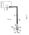
- a first embodiment of a device according to the invention in the form of a welding device 2 is shown, which is formed in this embodiment for performing an arc welding process and has a trained as a welding torch welding head 4 for delivering welding energy to be welded to workpieces.
- a welding energy source 6 is provided, which supplies a welding current to the welding head 4. The welding current flows through a in Fig.
- welding wire which is continuously supplied to the welding head 4 during the welding process and forms an electrode in the arc welding process, wherein when forming a welded joint, such as a weld, an arc between the welding wire 8 and the workpiece to be welded burns ,
- the welding current is supplied to the welding head 4 via a supply line 10.
- a control line 12 is provided to transmit control signals from the welding head 4 to the source 6.
- the welding device 2 comprises sensor means for sensing the position or changes in position of the welding head 4 relative to a reference position of the welding head 4 and / or to the workpieces to be welded such that at least one characteristic of the welding method is dependent on the sensed position and / or or long changes can be influenced.
- the sensor means in this embodiment have a first sensor 14 for sensing a rotational position and / or of rotational position changes of the welding head 4, which will be described below with reference to FIGS. 3 and 4 is explained in more detail.
- the sensor means further comprise in this embodiment, a second sensor 16, which senses translational movements as well as the speed and / or acceleration of a translational movement of the welding head.
- the welding device 2 further comprises control means connected to the sensors 14, 16 for automatic control and / or regulation of at least one parameter of the welding process as a function of the position and / or changes in position of the welding head 4 sensed by the sensors 14, 16.
- the control means comprise in this embodiment, a control unit 18, outputs of the sensors 14, 16 input signals of the control unit 14, the output signals are fed to a built-in source 6 control unit 20, which in dependence on the output signals of the control unit 18 characteristics of the welding process, in particular controls or regulates the amplitude of a welding current supplied by the source 6 to the welding head 4.
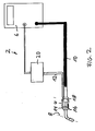
- a second embodiment of a welding device 2 according to the invention is shown, which differs from the embodiment according to FIG Fig. 1 differs in that the controller 20 is not integrated into the source 6, but is designed as a separate control unit.
- Fig. 3 is highly schematic illustrates the operation of the first sensor 14.
- the first sensor 14 has a housing designed as a hollow body 22, which in this embodiment has substantially the shape of a regular octahedron inside which a small amount of mercury 24 is contained.
- a pair of electrical contacts are arranged, of which Fig. 1 only a pair of contacts with the reference numerals 38, 40 is provided.
- the housing 24 in the in Fig. 1 shown rotational position is. Since the first sensor 14 is rotatably mounted on the welding head 4, it can be seen in this way that the welding head 4 in the in Fig. 1 is shown position.
- the mercury 24 collects in the region of the tip 30 and establishes an electrically conductive connection between the contacts associated with this tip 30, so that a control current can flow between these contacts. In this way, it can be determined by the control unit 18, that the housing 22 and thus also the welding head 4 in a opposite Fig. 1 respectively.
- Fig. 3 is rotated by 90 ° in a clockwise direction. In this way, any changes in the rotational position of the housing 22 and thus of the welding head 4 can be seen around all three axes in space.
- pairs of contacts 38, 40 at the tips 26, 28, 30, 32, 34, 36 of the housing is to be understood merely by way of example. To make the detection of changes in position more accurate, additional pairs of contacts 38, 40 may be provided.
- first sensor 14 whose housing 20 may be formed differently, for example, as a ball 42, as in Fig. 4 shown.
- a particularly accurate detection of changes in the rotational position of the housing 22 of the first sensor 14 and thus of the welding head 4 is possible.
- the welding of four plates 44, 46, 48, 50, located in Fig. 5 extend perpendicular to the plane of the drawing, with a fifth plate 52, the in Fig. 5 in the drawing plane.
- the welding head 4 in Fig. 5 moved to the left in the direction of an arrow 54 along the joint area of the plates 44, 52, wherein between the in Fig. 5 Welding wire, not shown, and the plates 44, 52 to be welded together form an arc, which leads to the formation of a welded joint in the form of a weld.
- the source 6 in this case leads the welding head 4 to a welding current with an amplitude of for example 150 A to.
- the first sensor 14 senses the rotational position of the welding head 4 relative to that in FIG Fig. 1 and 5 shown Reference position, while the second sensor 16, the speed of movement of the welding head 4 in the direction of arrow 54 senses.
- a corresponding signal is transmitted from the control unit 18 to the control unit of the source 6, which then increases the amplitude of the welding current to keep the path energy constant. If, on the other hand, it is determined by the second sensor 16 that the speed with which the welding head 4 is moved in the direction of the arrow 54 is reduced, the control unit 18 transmits to the control unit 20 a corresponding signal, which then determines the amplitude of the signal from the source 6 reduced welding current available. In this way it is ensured that the path energy remains constant during the welding process.
- the rotational position of the welding head 4 is changed, for example, by an axis perpendicular to the plane of the drawing, as in FIG Fig. 6 illustrated, this change in the rotational position is detected by the first sensor 14 and a corresponding signal transmitted by the control unit 18 to the control unit 20.
- the control unit 20 can then influence at least one parameter of the welding process, for example, in turn, the amplitude of the welding current, in order to obtain an optimum welding result.
- the welding head 4 If the welding head 4 is again rotated about an axis perpendicular to the plane to form a weld between the plate 46 and the plate 52 and is welded accordingly in the climbing position, so the change in the rotational position by the detected first sensor 14, and the control unit 18 transmits the controller 20 of the source 6, a corresponding signal. Since welding in the riser position involves welding at a slower speed than welding in the trough position, the controller 20 then reduces the welding current, which may then be 90A, for example.
- the controller 20 may control the welding current so that during a relatively high speed welding movement of the welding head 4, a relatively high welding current and during a movement of the welding head 4 at a relatively low speed, in particular at standstill, a reduced welding current is used.
- the controller 20 may in response to the output signal of the sensors 14, 16 and a resulting output of the control unit 18 again affect at least one parameter of the welding process, for example, the amplitude of the welding current, for example, increase.
- the control unit 20 of the source 6 reduces the amplitude of the welding current to such an extent that the material of the plates 48, 52 to be welded together is just so far liquefied
- the welding current amplitude can be reduced to 80 A when welding in overhead position.
- the welding current can be increased again when it is determined from the output signal of the first sensor 14 that the welding head 4 is rotated again to form a welding seam between the plate 50 and the plate 52 in case position.
- the welds required to connect the plates 44, 46, 48, 50 can be formed without exposing the arc, wherein the influencing of parameters of the welding process, in the described embodiment of the welding current, automatically by the control unit 18 and the control unit 20 in dependence output signals of the sensors 14, 16 of the sensor means take place without the need for manual intervention by a worker.
- the control unit 20 may in this case be preprogrammed so that the welding result is optimized as a function of the respective position or change in position of the welding head 4.
- an operating device 56 for example, for the manual selection of certain welding programs, be provided, and the respective selected Sch healthgrogramm can be displayed via a display device 58.
- Fig. 10 represents a characteristic field, where A1 to An denote different welding tasks and P1 to Pn denote different positions of the welding head.
- the assignment of values of the characteristic variables can take place as a function of the respective welding task and in dependence on the respective position of the welding head, wherein the welding tasks may differ, for example, with regard to the thickness and / or the material of the workpieces to be welded together.
- Fig. 11 is a highly schematic representation of a container formed of sheets to be welded together.
- a first welding task namely forming a weld in the tub position between a bottom plate 60 and a vertical side plate 62, starting from a point P2 second welding task, namely forming a weld seam as a stitching seam between a vertical side plate 64 and a vertical side plate 66 and starting from a point P3 a third welding task, namely forming a weld seam as an overhead seam between the vertical Side plate 66 and an upper plate 68 is run.
- the welding device 2 is first moved to the reference point P0 and the achievement of the reference point P0 by pressing, for example, a button of the operating device 56 is displayed to the control means. If the welding device 2 is moved starting from the reference point P0, then the sensor means detect the position and / or position changes of the welding device in three-dimensional space. If the welding device is moved along the x-axis, for example, this movement is detected by the sensor means. When the point P1 is reached, the control means allocate values to the parameters of the welding process which are optimally adapted to the welding task to be carried out there, namely welding in the tub position. The worker can thus create the weld between the vertical side panel 62 and the floor panel 60.
- the sensor means When the welding device is subsequently moved in the direction of the point P2, the sensor means again sense the position of the working head of the welding device 2 or changes in position in the three-dimensional space. Reaching point P2 is indicated to the control means by corresponding output signals from the sensor means, the control means then assigning values to the welding process to the welding task to be performed starting from point P2, namely forming a weld between the sheets 64, 68 are optimally adapted. After that, the worker can form the corresponding weld.
- the sensor means feel again the position of the welding head 4 of the welding device 2 or changes in position in three-dimensional space. If output signals of the sensor means indicate to the control means that the welding head 4 of the welding device 2 is at the point P3, then the control means optimally allocate to the characteristics of the welding process values corresponding to the welding task to be performed, namely forming a weld in overhead position are adapted. After that, the worker can form the corresponding weld.
- any parameters of the welding process can be used and influenced.
- each refer to a welding in the tub position can be carried out in the implementation of the first welding task with a welding current, which is adapted to a welding thicker sheets together, while in second welding task can be performed with a welding current, which is adapted to a welding of thinner sheets. This results in a particularly high degree of flexibility with regard to the influencing of the parameters.
Abstract
Description
Die Erfindung betrifft eine Vorrichtung der im Oberbegriff des Anspruchs 1 genannten Art zur Ausführung eines Füge-, Trenn- oder Oberflächenbehandlungsverfahrens, insbesondere eines Schweißverfahrens.The invention relates to a device of the type mentioned in the preamble of claim 1 for carrying out a joining, separating or surface treatment method, in particular a welding method.
Derartige Vorrichtungen sind beispielsweise in Form von Schweißvorrichtungen allgemein bekannt und dienen beispielsweise zur Durchführung von Lichtbogen-Schweißverfahren.Such devices are well known, for example in the form of welding devices and are used for example for performing arc welding process.
Wird beispielsweise mittels eines Lichtbogen-Schweißverfahrens eine Schweißaufgabe ausgeführt, die darin besteht, beispielsweise bei der Herstellung eines Behälters ohne Aussetzen des Lichtbogens eine zusammenhängende Schweißnaht zu bilden, die einen horizontalen Nahtabschnitt aufweist (Wannenposition), an den sich ein vertikal verlaufender Nahtabschnitt (Steigposition), danach wiederum ein horizontal verlaufender Nahtabschnitt (Überkopfposition) und schließlich wiederum ein vertikal verlaufender Nahtabschnitt (Fallposition) anschließt, der an den zuerst gebildeten horizontal verlaufenden Nahtabschnitt anschließt, so ist es erforderlich, daß ein die Schweißvorrichtung bedienender Werker die Lage des Schweißkopfes während des Schweißvorganges relativ zu den zu verschweißenden Werkstücken ändert.If, for example, by means of an arc welding process a welding task is carried out, which consists, for example in the production of a container without exposing the arc, to form a coherent weld having a horizontal seam portion (well position) to which a vertically extending seam portion (rising position) , then again a horizontally extending seam portion (overhead position) and finally a vertical seam portion (fall position) connects, which adjoins the first formed horizontally extending seam portion, it is necessary that a welding operator operating the position of the welding head during the welding process changes relative to the workpieces to be welded.
Hierbei ist es unter Umständen wünschenswert oder erforderlich, Werte von Kenngrößen des Schweißverfahrens an die jeweilige Lage des Schweißkopfes anzupassen. Beispielsweise ist es wünschenswert, die Stromstärke des Schweißstromes in der Überkopfposition des Brenners zu verringern, um zu verhindern, daß flüssiges Material der zu verschweißenden Werkstücke bzw. eines Schweißdrahtes herabtropft. Ferner kann es beispielsweise wünschenswert sein, in der Steigposition und der Fallposition die Stromstärke des Schweißstromes ebenfalls zu verringern, um so der Tatsache Rechnung zu tragen, daß in der Steigposition und der Fallposition der Schweißkopf meist mit einer geringeren Geschwindigkeit relativ zu den zu verschweißenden Werkstücken bewegt wird als in der Wannenposition.Under certain circumstances, it may be desirable or necessary to adapt values of parameters of the welding process to the respective position of the welding head. For example, it is desirable to reduce the amperage of the welding current in the overhead position of the burner to prevent liquid material from dripping down the workpieces to be welded or a welding wire. Further, it may be desirable, for example, in the climbing position and the fall position to reduce the current strength of the welding current, so as to take into account the fact that moves in the climbing position and the drop position of the welding head usually at a lower speed relative to the workpieces to be welded is considered in the tub position.
Zu diesem Zweck ist es bekannt, über eine an der Schweißvorrichtung vorgesehene Bedieneinrichtung unterschiedliche Schweißprogramme anzuwählen, in denen den Kenngrößen des Schweißverfahrens, beispielsweise der Amplitude des Schweißstromes vorbestimmte Werte zugeordnet sind.For this purpose, it is known to select different welding programs via an operating device provided on the welding device, in which predetermined values are assigned to the parameters of the welding method, for example the amplitude of the welding current.
Ein Nachteil dieser bekannten Schweißvorrichtung besteht darin, daß die Wahl des jeweils zutreffenden Schweißprogrammes durch den Werker erfolgen muß, was in der Praxis dazu geführt hat, daß der Werker aus Gründen der Zeitersparnis und Bequemlichkeit möglicherweise sämtliche Teile einer Schweißaufgabe mit demselben Schweißprogramm ausführt, um das Umschalten zwischen den Schweißprogrammen zu vermeiden. Da ein Schweißprogramm stets nur für einen Teil der Schweißaufgabe, beispielsweise das Schweißen in Wannenposition, optimiert sein kann, führt dies in der Praxis dazu, daß die Qualität der Schweißnaht im Vergleich zu einer Schweißnaht, die unter Verwendung des jeweils optimierten Schweißprogrammes für jeden Nahtabschnitt gebildet worden ist, verschlechtert ist.A disadvantage of this known welding device is that the choice of the applicable welding program must be made by the worker, which has led in practice to the fact that the worker may perform all parts of a welding task with the same welding program for the sake of saving time and convenience to the To avoid switching between the welding programs. Since a welding program can always be optimized only for a part of the welding task, for example welding in trough position, this leads in practice to the quality of the weld seam in comparison to a weld seam which is optimized using the respective Welding program has been formed for each seam section is deteriorated.
Der Erfindung liegt die Aufgabe zugrunde, eine Vorrichtung der im Oberbegriff des Anspruchs 1 genannten Art anzugeben, die den Nachteil der bekannten Vorrichtung nicht aufweist, bei der also die Arbeitsergebnisse bei der Durchführung eines Füge-, Trenn- oder Oberflächenbehandlungsverfahrens verbessert sind, beispielsweise bei einem Schweißverfahren die Qualität der gebildeten Schweißverbindung erhöht ist, und die einfach und bequem bedienbar ist.The invention has for its object to provide a device referred to in the preamble of claim 1, which does not have the disadvantage of the known device, in which therefore the work results in performing a joining, cutting or surface treatment method are improved, for example in a Welding method, the quality of the welded joint formed is increased, and which is easy and convenient to operate.
Diese Aufgabe wird durch die im Anspruch 1 angegebene Lehre gelöst.This object is achieved by the teaching defined in claim 1.
Der Grundgedanke der erfindungsgemäßen Lehre besteht beispielsweise und insbesondere in Bezug auf eine Schweißvorrichtung darin, die Lage des Schweißkopfes und/oder Lageänderungen des Schweißkopfes relativ zu einer Bezugslage des Arbeiskopfes und/oder einem Bezugspunkt im Raum und/oder den zu verschweißenden Werkstücken durch Sensormittel abzufühlen. Auf diese Weise können die Kenngrößen des Schweißverfahrens oder wenigstens eine dieser Kenngrößen in Abhängigkeit von der abgefühlten Lage und/oder Lageänderung hinsichtlich ihrer Werte beeinflußt werden. Insbesondere können den Kenngrößen des Schweißverfahrens Werte zugeordnet werden, die an die jeweilige Schweißaufgabe angepaßt sind. Die Zuordnung der Werte erfolgt hierbei erfindungsgemäß in Abhängigkeit von der abgefühlten Lage und/oder Lageänderungen des Schweißkopfes aus der bzw. aus denen sich ergibt, welche Schweißaufgabe jeweils auszuführen ist.The basic idea of the teaching according to the invention consists, for example and in particular in relation to a welding device, of sensing the position of the welding head and / or changes in position of the welding head relative to a reference position of the workhead and / or a reference point in the space and / or the workpieces to be welded by sensor means. In this way, the characteristics of the welding process or at least one of these parameters can be influenced in terms of their values as a function of the sensed position and / or positional change. In particular, the parameters of the welding process can be assigned values which are adapted to the respective welding task. According to the invention, the values are assigned as a function of the sensed position and / or changes in position of the welding head from or from which results, which welding task is to be carried out in each case.
Auf diese Weise ist beispielsweise die Bedienung einer als Schweißvorrichtung ausgebildeten Vorrichtung wesentlich vereinfacht und die Qualität der mittels der erfindungsgemäßen Vorrichtung erzeugten Schweißverbindungen, also beispielsweise von Schweißpunkten oder Schweißnähten, wesentlich erhöht. Erfindungsgemäß kann beispielsweise in Abhängigkeit von einer abgefühlten Lageänderung des Schweißkopfes ein optisches oder akustisches Signal erzeugt werden, das dem Werker anzeigt, daß ein anderes Schweißprogramm zu wählen ist. Beispielsweise kann dann, wenn nach dem Bilden einer Schweißnaht in Wannenposition der Schweißkopf um etwa 90° gedreht wird, um beispielsweise in Steigposition zu schweißen, ein Signal erzeugt werden, das dem Werker anzeigt, daß nunmehr ein für das Schweißen in Steigposition optimiertes Schweißprogramm zu wählen ist.In this way, for example, the operation of a device designed as a welding device is substantially simplified and the quality of the means of inventive device produced welded joints, so for example, welds or welds, significantly increased. According to the invention, for example, depending on a sensed change in position of the welding head, an optical or acoustic signal can be generated, which indicates to the worker that another welding program is to be selected. For example, if, after forming a weld in trough position, the welding head is rotated about 90 °, for example, to weld in rising position, a signal may be generated which indicates to the worker that now to select a welding program optimized for welding in rising position is.
Insbesondere und vorzugsweise kann erfindungsgemäß die Beeinflussung von Kenngrößen des betreffenden Verfahrens hinsichtlich ihrer Werte, beispielsweise eines Schweißverfahrens jedoch auch automatisch erfolgen. Beispielsweise können Steuermittel vorgesehen sein, die anhand von Ausgangssignalen der Sensormittel die Lage des Arbeitskopfes bzw. Lageänderungen des Arbeitskopfes erkennen und in Abhängigkeit von der erkannten Lage bzw. Lageänderung Kenngrößen des Verfahrens hinsichtlich ihrer Werte beeinflussen. Auf diese Weise ist die Bedienung der erfindungsgemäßen Vorrichtung wesentlich vereinfacht und die Qualität von beispielsweise mittels einer erfindungsgemäßen Schweißvorrichtung erzeugten Schweißverbindungen wesentlich erhöht.In particular and preferably, according to the invention, however, the influencing of parameters of the relevant method with regard to their values, for example a welding method, can also take place automatically. For example, control means can be provided which detect the position of the working head or changes in position of the working head based on output signals of the sensor means and influence the process parameters in terms of their values as a function of the detected position or position change. In this way, the operation of the device according to the invention is substantially simplified and the quality of, for example, substantially increased by means of a welding device according to the invention welded joints.
Unter einem Arbeitskopf wird erfindungsgemäß derjenige Teil einer erfindungsgemäßen Vorrichtung verstanden, über den während des Bearbeitungsvorganges auf die zu bearbeitenden Werkstücke eingewirkt, also beispielsweise während eines Schweißvorganges die Schweißenergie in die miteinander zu verschweißenden Werkstükke eingebracht wird. Bei einem Widerstands-Schweißverfahren kann der Schweißkopf beispielsweise durch eine Schweißzange gebildet sein, während er bei einem Lichtbogen-Schweißverfahren beispielsweise durch einen Brenner, an dem der Schweißdraht geführt ist, gebildet sein kann.According to the invention, a working head is understood to mean that part of a device according to the invention via which the workpieces to be machined are acted upon during the machining process, that is, for example, the welding energy is introduced into the workpieces to be welded together during a welding operation. In a resistance welding process For example, the welding head may be formed by welding tongs, while it may be formed in an arc welding process by, for example, a torch on which the welding wire is guided.
Unter einem Schweißvorgang wird erfindungsgemäß der Vorgang der Bildung einer Schweißverbindung, also beispielsweise eines Schweißpunktes oder einer Schweißnaht verstanden.Under a welding process according to the invention, the process of forming a welded joint, so for example, a weld or a weld understood.
Die erfindungsgemäß vorgesehenen Sensormittel können entsprechend den jeweiligen Anforderungen die Lage und/oder Lageänderungen des Arbeitskopfes relativ zu einer Bezugslage und/oder einem Bezugspunkt im Raum erfassen, wobei die Lageänderungen sowohl translatorische als auch rotative Lageänderungen sowie Kombinationen von translatorischen mit rotativen Lageänderungen sein können.The inventively provided sensor means can detect the position and / or changes in position of the working head relative to a reference position and / or a reference point in space according to the respective requirements, wherein the changes in position can be both translational and rotational position changes and combinations of translational with rotational position changes.
Hierbei ist es möglich, daß Lageänderungen des Arbeitskopfes während des Einwirkens auf ein und dasselbe Werkstück erfaßt werden. Es ist auch möglich, Lageänderungen zu erfassen, bei denen nach einer Lageänderung auf ein anderes Werkstück eingewirkt wird. Wird beispielsweise mittels einer Schweißvorrichtung eine Schweißaufgabe ausgeführt, die sich auf ein erstes Werkstück bezieht, so kann beispielsweise ein Wechsel zu einem anderen Werkstück durch die erfindungsgemäßen Sensormittel erfaßt und der Wert wenigstens einer Kenngröße des Schweißverfahrens an die in Bezug auf dieses Werkstück auszuführende Schweißaufgabe angepaßt werden, ggf. im Zusammenwirken mit einem manuellen Eingriff des Werkers, der beispielsweise die bei diesem Werkstück auszuführende Schweißaufgabe in die Vorrichtung eingibt.It is possible that changes in position of the working head during the action on one and the same workpiece are detected. It is also possible to detect changes in position, which are acted upon by a change in position on another workpiece. If, for example, a welding task is carried out by means of a welding device, which relates to a first workpiece, then a change to another workpiece can be detected by the sensor means according to the invention and the value of at least one parameter of the welding process can be adapted to the welding task to be performed with respect to this workpiece optionally in cooperation with a manual intervention of the worker who enters, for example, the welding task to be performed on this workpiece in the device.
Es ist erfindungsgemäß jedoch anhand der Ausgangssignale der Sensormittel jedoch auch möglich, die Erkennung, daß nach einer Lageänderung ein neues Werkstück zu bearbeiten ist, und die daraus resultierende Anpassung von Werten von Kenngrößen beispielsweise des Schweißverfahrens automatisch auszuführen, beispielsweise dann, wenn in einer vorbestimmten Reihenfolge unterschiedliche, räumlich voneinander getrennte Werkstücke zu bearbeiten sind, beispielsweise bei einer vorbestimmten Reihenfolge von in Vertikalrichtung zueinander beabstanden zu verschweißenden Werkstücken.However, according to the invention, it is based on the output signals However, the sensor means also possible, the recognition that after a change in position, a new workpiece to edit, and the resulting adjustment of values of parameters, for example, the welding process automatically execute, for example, if in a predetermined order different, spatially separated workpieces to are, for example, in a predetermined order of spaced from each other in the vertical direction to be welded workpieces.
Die erfindungsgemäße Vorrichtung ist besonders gut zur Ausführung beliebiger Schweißverfahren geeignet. Insbesondere und beispielsweise kann das Schweißverfahren ein Widerstands-Schweißverfahren, ein Strahlschweißverfahren, ein Gasschmelz-Schweißverfahren oder ein Lichtbogen-Schweißverfahren, insbesondere ein Schutzgas-Lichtbogen-Schweißverfahren sein.The device according to the invention is particularly well suited for carrying out any desired welding process. In particular, and for example, the welding method may be a resistance welding method, a beam welding method, a gas fusion welding method or an arc welding method, in particular an inert gas arc welding method.
In Bezug auf andere Füge-, Trenn- oder Oberflächenbehandlungsverfahren besteht der Grundgedanke der erfindungsgemäßen Lehre darin, Kenngrößen des Füge-, Trenn- oder Oberflächenbehandlungsverfahrens in Abhängigkeit von der Lage bzw. von Lageänderungen des jeweiligen Arbeitskopfes zu beeinflussen. Dementsprechend kann die erfindungsgemäße Vorrichtung auch als beliebige andere Füge-, Trenn- oder Oberflächenbehandlungsvorrichtung ausgebildet sein. Beispielsweise kann die erfindungsgemäße Vorrichtung als Schneidvorrichtung zur Durchführung beispielsweise eines Laser-Schneidverfahrens ausgebildet sein. Die erfindungsgemäße Vorrichtung kann beispielsweise auch als Klebevorrichtung zur Durchführung eines Klebeverfahrens ausgebildet sein, wobei der Arbeitskopf der Vorrichtung dann durch eine Klebepistole gebildet sein kann. Ferner kann die erfindungsgemäße Vorrichtung beispielsweise auch als Farbsprühvorrichtung ausgebildet sein, wobei der Arbeitskopf dann durch eine Farbsprühpistole oder dergleichen gebildet sein kann. Erfindungsgemäß kann in diesem Fall beispielsweise der Druck, mit dem die Farbe versprüht wird, erhöht werden, wenn der Sprühstrahl nach oben gerichtet wird, also mit der Farbsprühpistole über Kopf gearbeitet wird.With regard to other joining, separating or surface treatment methods, the basic idea of the teaching according to the invention is to influence parameters of the joining, separating or surface treatment method as a function of the position or changes in position of the respective working head. Accordingly, the device according to the invention can also be designed as any other joining, separating or surface treatment device. For example, the device according to the invention can be designed as a cutting device for carrying out, for example, a laser cutting method. The device according to the invention can also be designed, for example, as an adhesive device for carrying out an adhesive method, wherein the working head of the device can then be formed by a glue gun. Furthermore, the device according to the invention can also be used, for example, as a paint spraying device be formed, wherein the working head can then be formed by a paint spray gun or the like. According to the invention, in this case, for example, the pressure at which the paint is sprayed, be increased when the spray is directed upward, so is worked with the paint spray gun overhead.
Eine außerordentlich vorteilhafte Weiterbildung der erfindungsgemäßen Lehre sieht mit den Sensormitteln verbundene Steuermittel zur selbsttätigen Steuerung und/oder Regelung wenigstens einer Kenngröße des Füge-, Trenn- oder Oberflächenbehandlungsverfahrens, insbesondere des Schweißverfahrens, in Abhängigkeit von der durch die Sensormittel abgefühlten Lage und/oder Lageänderungen des Arbeitskopfes vor. Bei dieser Ausführungsform ist eine Steuerung bzw. Regelung wenigstens einer Kenngröße des Füge-, Trenn- oder Oberflächenbehandlungsverfahrens, insbesondere des Schweißverfahrens, in Abhängigkeit von der durch die Sensormittel abgefühlten Lage und/oder Lageänderung des Arbeitskopfes ermöglicht, so daß die Bedienung der erfindungsgemäßen Vorrichtung besonders einfach gestaltet und die Qualität beispielsweise einer Schweißverbindung weiter erhöht ist.An extraordinarily advantageous development of the teaching according to the invention provides control means connected to the sensor means for the automatic control and / or regulation of at least one parameter of the joining, separating or surface treatment method, in particular of the welding method, in dependence on the position and / or positional changes sensed by the sensor means Working head. In this embodiment, a control or regulation of at least one characteristic of the joining, cutting or surface treatment method, in particular the welding process, depending on the sensed by the sensor means position and / or change in position of the working head allows, so that the operation of the device according to the invention particularly simply designed and the quality of a welded joint is further increased.
Eine vorteilhafte Weiterbildung der erfindungsgemäßen Vorrichtung sieht vor, daß die Vorrichtung als Schweißvorrichtung zur Ausführung eines Schweißverfahrens und der Arbeitskopf als Schweißkopf zur Abgabe von Schweißenergie an die zu verschweißenden Werkstücke ausgebildet ist.An advantageous development of the device according to the invention provides that the device is designed as a welding device for performing a welding process and the working head as a welding head for delivering welding energy to the workpieces to be welded.
Die Beeinflussung von Werten von Kenngrößen des Füge-, Trenn- oder Oberflächenbehandlungsverfahrens, insbesondere des Schweißverfahrens, kann bei der vorgenannten Ausführungsform auf beliebige geeignete Weise erfolgen. Eine vorteilhafte Weiterbildung sieht vor, daß die Steuermittel mit einer den Schweißkopf mit Schweißenergie versorgenden Schweißenergie-Quelle zur Ansteuerung derselben verbunden sind, derart, daß wenigstens eine Kenngröße des Schweißverfahrens in Abhängigkeit von der durch die Sensormittel abgefühlten Lage und/oder Lageänderung des Schweißkopfes an der Schweißenergie-Quelle steuer- und/oder regelbar ist. Bei dieser Ausführungsform erfolgt die Steuerung bzw. Regelung von Kenngrößen des Schweißverfahrens an der Schweißenergie-Quelle. Die Steuermittel können hierbei in ein Steuergerät der Schweißenergie-Quelle integriert oder durch ein separates Steuergerät gebildet sein, das eingangsseitig mit den Sensormitteln und ausgangsseitig mit einem Steuergerät der Schweißenergie-Quelle verbunden ist.The influencing of values of parameters of the joining, separating or surface treatment method, in particular of the welding method, in the aforementioned embodiment, in any suitable manner respectively. An advantageous development provides that the control means are connected to a welding head supplying the welding head with welding energy source for driving the same, such that at least one characteristic of the welding process in dependence on the sensed by the sensor means position and / or change in position of the welding head on the Welding power source is controlled and / or regulated. In this embodiment, the control or regulation of parameters of the welding process takes place at the welding energy source. The control means can in this case be integrated in a control unit of the welding energy source or formed by a separate control unit, which is connected on the input side to the sensor means and on the output side to a control unit of the welding energy source.
Anzahl, Anordnung und konstruktive Gestaltung von Sensoren der Sensormittel sind in weiten Grenzen wählbar. Eine vorteilhafte Weiterbildung der erfindungsgemäßen Lehre sieht vor, daß die Sensormittel wenigstens einen Sensor zum Abfühlen einer Rotationslage und/oder von rotativen Lageänderungen des Arbeitskopfes aufweisen. Bei dieser Ausführungsform ist durch den Sensor beispielsweise feststellbar, ob der Arbeitskopf gedreht wird, um beispielsweise bei einer Schweißvorrichtung von einem Schweißen in Wannenposition auf ein Schweißen in Steigposition überzugehen.Number, arrangement and structural design of sensors of the sensor means can be selected within wide limits. An advantageous development of the teaching according to the invention provides that the sensor means have at least one sensor for sensing a rotational position and / or rotational position changes of the working head. In this embodiment, it can be determined by the sensor, for example, whether the working head is rotated, for example, in a welding device of a welding in trough position on a welding in climb position.
Eine andere Weiterbildung der erfindungsgemäßen Lehre sieht vor, daß die Sensormittel wenigstens einen Sensor zum Abfühlen translatorischer Lageänderungen des Arbeitskopfes aufweisen. Bei dieser Ausführungsform ist durch den Sensor beispielsweise abfühlbar, ob sich der Arbeitskopf translatorisch bewegt, beispielsweise beim Bilden einer Schweißnaht. Zum Abfühlen translatorischer Lageänderungen des Arbeitskopfes können beliebige geeignete Sensoren bzw. Sensoranordnungen verwendet werden. Beispielsweise kann an dem Arbeitskopf ein Ultraschallsender angeordnet sein, der Ultraschallwellen abstrahlt, die von einem ortsfesten Ultraschallempfänger empfangen werden. Aus der Laufzeit der Ultraschallwellen von dem Ultraschallsender und damit dem Arbeitskopf zu dem Ultraschallempfänger kann dann der Abstand des Arbeitskopfes von dem Ultraschallsender ermittelt werden. In hierzu entsprechender Weise können die Ultraschallwellen von zwei räumlich zueinander beabstandet angeordneten Ultraschallempfängern empfangen werden, so daß aufgrund der Abstandsänderung des Arbeitskopfes zu jedem der beiden Ultraschallempfänger translatorische Lageänderungen des Arbeitskopfes ermittelt werden können. Um Lageänderungen des Arbeitskopfes im dreidimensionalen Raum eindeutig zu erfassen, können in hierzu entsprechender Weise drei räumlich zueinander beabstandete Ultraschallempfänger vorgesehen sein, so daß sich aus dem jeweiligen Abstand des Arbeitskopfes von jedem der Ultraschallempfänger die Lage des Arbeitskopfes im dreidimensionalen Raum bzw. Lageänderungen eindeutig erfassen läßt. Insbesondere translatorische Lageänderungen können auch beispielsweise mit optischen Sensormitteln erfaßt werden. Der Abstand des Arbeitskopfes von einem Bezugspunkt ist beispielsweise mittels eines Laser-Interferometers ermittelbar. In hierzu entsprechender Weise sind translatorische Lageänderungen des Arbeitskopfes über zwei voneinander unabhängige Laser-Interferometer und Lageänderungen des Arbeitskopfes im dreidimensionalen Raum mittels dreier voneinander unabhängiger Laser-Interferometer erfaßbar.Another development of the teaching according to the invention provides that the sensor means have at least one sensor for sensing translational changes in position of the working head. In this embodiment, for example, it can be sensed by the sensor whether the working head moves in a translatory manner, for example when forming a weld seam. To feel translational Changes in position of the working head can be used with any suitable sensors or sensor arrangements. For example, an ultrasonic transmitter can be arranged on the working head, which emits ultrasonic waves which are received by a fixed ultrasonic receiver. From the duration of the ultrasonic waves from the ultrasonic transmitter and thus the working head to the ultrasonic receiver then the distance of the working head of the ultrasonic transmitter can be determined. In this way, the ultrasonic waves of two spatially spaced apart arranged ultrasonic receivers can be received, so that due to the change in distance of the working head to each of the two ultrasonic receiver translational changes in position of the working head can be determined. In order to clearly detect changes in position of the working head in three-dimensional space, three spatially mutually spaced ultrasonic receivers can be provided, so that the position of the working head in the three-dimensional space or position changes can be clearly detected from the respective distance of the working head of each of the ultrasonic receivers , In particular, translational position changes can also be detected, for example, with optical sensor means. The distance of the working head from a reference point can be determined, for example, by means of a laser interferometer. In this way, translational changes in position of the working head via two independent laser interferometer and changes in position of the working head in three-dimensional space by means of three mutually independent laser interferometer can be detected.
Eine Weiterbildung der vorgenannten Ausführungsform sieht vor, daß der Sensor die Geschwindigkeit und/oder Beschleunigung einer translatorischen und/oder rotativen Bewegung des Arbeitskopfes abfühlt. Auf diese Weise kann eine noch weitergehende Beeinflussung von Kenngrößen des Schweißverfahrens erfolgen. Beispielsweise kann bei einer Schweißvorrichtung die Amplitude des Schweißstromes in Abhängigkeit von der Geschwindigkeit, mit der sich der Schweißkopf beim Bilden einer Schweißverbindung über die miteinander zu verschweißenden Werkstücke bewegt, beeinflußt werden. Um beispielsweise die sogenannte Streckenenergie, also die pro Längeneinheit einer Schweißnaht in die zu verschweißenden Werkstücke eingebrachte Schweißenergie, konstant zu halten, kann beim Schweißen mit einer relativ geringen Geschwindigkeit des Schweißkopfes relativ zu den zu verschweißenden Werkstücken eine vorbestimmte Amplitude des Schweißstromes gewählt werden, während beim Erhöhen der Geschwindigkeit die Amplitude des Schweißstromes erhöht wird. Zum Abfühlen einer Beschleunigung des Arbeitskopfes können beispielsweise Sensoren verwendet werden, wie sie unter den Bezeichnungen MMA 6260 Q, MMA 6261 Q, MMA 6262 Q und MMA 6263 Q von der Firma Freescale Semiconductor, Inc. Alma School Road Chandler, Arizona, USA (www.freescale.com), vertrieben werden.A development of the aforementioned embodiment provides that the sensor speed and / or acceleration of a translatory and / or rotary movement of the working head. In this way, an even further influencing of parameters of the welding process can take place. For example, in a welding apparatus, the amplitude of the welding current may be influenced depending on the speed with which the welding head moves over the workpieces to be welded together in forming a welded joint. For example, in order to keep the so-called line energy, ie the welding energy introduced per unit of length of a weld into the workpieces to be welded, a predetermined amplitude of the welding current can be selected during welding at a relatively low speed of the welding head relative to the workpieces to be welded, while Increasing the speed increases the amplitude of the welding current. For example, sensors such as MMA 6260 Q, MMA 6261 Q, MMA 6262 Q and MMA 6263 Q from Freescale Semiconductor, Inc., Alma School Road Chandler, Arizona, USA (www .freescale.com).
Entsprechend den jeweiligen Anforderungen kann der Arbeitskopf während des Bearbeitungsvorganges von Hand oder durch eine Handhabungseinrichtung, insbesondere einen Schweißroboter führbar sein.According to the respective requirements of the working head during the machining process by hand or by a handling device, in particular a welding robot can be feasible.
Bei der Ausführungsform, bei der die Vorrichtung eine Schweißvorrichtung zur Durchführung eines Schweißverfahrens ist, kann das Schweißverfahren ein Widerstands-Schweißverfahren, ein Strahlschweißverfahren, ein Gasschmelz-Schweißverfahren, ein Lichtbogen-Schweißverfahren, ein Schutzgas-Lichtbogen-Schweißverfahren, ein Bolzenschweißverfahren oder ein Laserstrahl-Schweißverfahren sein.In the embodiment in which the apparatus is a welding apparatus for performing a welding method, the welding method may include a resistance welding method, a beam welding method, a gas fusion welding method, an arc welding method, an inert gas arc welding method, a stud welding method, or a laser beam method. welding processes be.
Zur Durchführung eines Schweißverfahrens, bei dem die Schweißenergie über einen Schweißstrom bzw. eine Schweißspannung bereitgestellt wird, sieht eine Weiterbildung der erfindungsgemäßen Lehre vor, daß die in Abhängigkeit von einer durch die Sensormittel abgefühlten Lage und/oder Lageänderung des Schweißkopfes beeinflußbaren Kenngrößen des Schweißverfahrens wenigstens
- die Amplitude und/oder
- die Signalform, insbesondere Pulsform, und/oder
- die Pulsfrequenz und/oder
- die Pulsmodulation
- the amplitude and / or
- the waveform, in particular pulse shape, and / or
- the pulse rate and / or
- the pulse modulation
Wird die erfindungsgemäße Schweißvorrichtung zur Ausführung eines Widerstands-Schweißverfahrens verwendet, so sieht eine vorteilhafte Weiterbildung der erfindungsgemäßen Schweißvorrichtung vor, daß die in Abhängigkeit von der durch die Sensormittel abgefühlten Lage bzw. Lageänderung des Schweißkopfes beinflußbaren Kenngrößen des Schweißverfahrens eine Anpreßkraft wenigstens einer Schweißelektrode des Schweißkopfes an eines der zu verschweißenden Werkstücke umfassen.If the welding device according to the invention is used to carry out a resistance welding process, an advantageous further development of the welding device according to the invention provides that the parameters of the welding process which can be influenced depending on the position or change in position of the welding head sensed by the sensor means apply a contact pressure to at least one welding electrode of the welding head include one of the workpieces to be welded.
Eine vorteilhafte Weiterbildung einer erfindungsgemäßen Schweißvorrichtung, die zur Ausführung eines Lichtbogen-Schweißverfahrens, bei dem zusätzlicher Werkstoff in Form eines Schweißdrahtes zugeführt wird, verwendet wird, sieht vor, daß die in Abhängigkeit von der durch die Sensormittel abgefühlten Lage bzw. Lageänderungen des Schweißkopfes beeinflußbaren Kenngrößen des Schweißverfahrens eine Zuführgeschwindigkeit wenigstens eines an dem Schweißkopf geführten Schweißdrahtes umfassen.An advantageous development of a welding device according to the invention, which is used for carrying out an arc welding process in which additional material is supplied in the form of a welding wire, provides that the parameters which can be influenced as a function of the position or changes in position of the welding head sensed by the sensor means of the welding process comprise a feeding speed of at least one welding wire guided on the welding head.
Eine andere vorteilhafte Weiterbildung der erfindungsgemäßen Lehre sieht vor, daß die Vorrichtung ein Schweißbrenner ist.Another advantageous development of the teaching of the invention provides that the device is a welding torch.
Andere Weiterbildungen der erfindungsgemäßen Lehre sehen vor, daß die Vorrichtung eine Farbsprühvorrichtung, insbesondere eine Farbsprühpistole oder eine Klebevorrichtung, insbesondere Klebepistole, beispielsweise Heißklebepistole ist.Other developments of the teaching of the invention provide that the device is a paint spraying device, in particular a paint spray gun or an adhesive device, in particular glue gun, for example hot glue gun.
Die Position eines Sensors oder von Sensoren der Sensormittel relativ zu dem Arbeitskopf sind in beliebiger geeigneter Weise wählbar, solange sichergestellt ist, daß in der jeweils erforderlichen Weise die Lage bzw. Lageänderungen des Arbeitskopfes erfaßt werden können. Um eine besonders genaue Erfassung der Lage bzw. von Lageänderungen des Arbeitskopfes zu ermöglichen und zugleich einen konstruktiv einfachen Aufbau zu erreichen, sieht eine Weiterbildung der erfindungsgemäßen Lehre vor, daß wenigstens ein Sensor der Sensormittel an dem Arbeitskopf angeordnet, insbesondere in den Arbeitskopf integriert ist.The position of a sensor or sensors of the sensor means relative to the working head can be selected in any suitable manner, as long as it is ensured that in the respectively required manner, the position or position changes of the working head can be detected. In order to allow a particularly accurate detection of the situation or changes in position of the working head and at the same time to achieve a structurally simple construction, a development of the teaching according to the invention provides that at least one sensor of the sensor means is arranged on the working head, in particular integrated into the working head.
Erfindungsgemäß ist es jedoch auch möglich, daß wenigstens ein Sensor der Sensormittel am Körper eines die Vorrichtung benutzenden Werkers, insbesondere an dessen Hand oder Arm, tragbar ist, wie dies eine andere Weiterbildung der erfindungsgemäßen Lehre vorsieht.According to the invention, however, it is also possible that at least one sensor of the sensor means on the body of a device using the worker, in particular on his hand or arm, is portable, as provided for in another development of the teaching of the invention.
Eine Bezugslage des Arbeitskopfes kann bei der Herstellung der erfindungsgemäßen Vorrichtung bereits werksseitig vorgegeben sein. Beispielsweise kann die Bezugslage eine Lage sein, in der ein Schweißkopf so angeordnet ist, daß in Wannenposition, also unter Bildung einer im wesentlichen horizontal verlaufenden Schweißnaht, geschweißt wird. Eine vorteilhafte Weiterbildung der erfindungsgemäßen Lehre sieht jedoch vor, daß die Bezugslage des Arbeitskopfes und/oder ein Bezugspunkt im Raum durch einen Werker und/oder durch die Steuermittel wählbar ist. Bei dieser Ausführungsform ist es insbesondere möglich, die Bezugslage an die Gegebenheiten der jeweiligen Schweißaufgabe bzw. einen die Schweißvorrichtung benutzenden Werker anzupassen.A reference position of the working head can already be specified at the factory in the production of the device according to the invention. For example, the reference layer may be a layer in which a welding head is arranged so that in the trough position, that is, to form a substantially horizontally extending weld, welded. An advantageous development of the teaching according to the invention, however, provides that the reference position of the working head and / or a reference point in the room by a worker and / or by the control means is selectable. In this embodiment, it is particularly possible to adapt the reference position to the circumstances of the respective welding task or to a worker using the welding device.
Eine Weiterbildung der vorgenannten Ausführungsform sieht vor, daß die Steuermittel in Abhängigkeit von der gewählten Bezugslage und/oder der durch die Sensormittel abgefühlten Lage und/oder von Lageänderungen des Arbeitskopfes den Kenngrößen des Schweißverfahrens vorbestimmte Werte zuordnen. Bei dieser Ausführungsform können den Kenngrößen des Schweißverfahrens beispielsweise Werte entsprechend einer Kennlinie zugeordnet sein. Beispielsweise können beim Verschweißen von Blechen einer bestimmten Dicke dem Schweißen in der Wannenposition, dem Schweißen in der Steigposition, dem Schweißen in der Überkopfposition und dem Schweißen in der Fallposition jeweils ein Satz von Werten der Kenngrößen zugeordnet sein. Es ist jedoch auch möglich, die Zuordnung von Werten zu den Kenngrößen des Schweißverfahrens in Abhängigkeit von einem Kennlinienfeld vorzunehmen. So können den Kenngrößen beispielsweise Werte in Abhängigkeit von dem Material und/oder der Dicke der miteinander zu verschweißenden Werkstücke zugeordnet werden.A development of the aforementioned embodiment provides that the control means in dependence on the selected reference position and / or sensed by the sensor means position and / or changes in position of the working head to assign the characteristics of the welding process predetermined values. In this embodiment, for example, values corresponding to a characteristic may be assigned to the characteristics of the welding process. For example, when welding sheets of a given thickness, welding in the cup position, welding in the rising position, welding in the overhead position, and welding in the falling position may each be assigned a set of values of the characteristics. However, it is also possible to carry out the assignment of values to the characteristics of the welding process as a function of a characteristic field. For example, values can be assigned to the characteristics as a function of the material and / or the thickness of the workpieces to be welded together.
Eine andere vorteilhafte Weiterbildung der erfindungsgemäßen Lehre sieht vor, daß die Steuermittel Kenngrößen des Schweißverfahrens während des Schweißvorganges selbsttätig steuern bzw. regeln. Die Steuerung bzw. Regelung der Kenngrößen kann zeitlich bzw. räumlich, bezogen beispielsweise auf eine Schweißnaht, kontinuierlich oder diskret erfolgen.Another advantageous development of the teaching according to the invention provides that the control means automatically control or regulate parameters of the welding process during the welding process. The control or regulation of the parameters can be temporal or spatial, based for example on a weld, continuously or discretely.
Eine andere Weiterbildung der erfindungsgemäßen Lehre sieht eine Anzeigeeinrichtung zur Anzeige eines durch die Steuermittel in Abhängigkeit von Ausgangssignalen der Sensormittel gewählten Betriebsmodus der Vorrichtung vor. Bei dieser Ausführungsform kann ein Betriebsmodus der Vorrichtung, beispielsweise ein durch die Steuermittel gewähltes Schweißprogramm, durch die Anzeigeeinrichtung angezeigt werden, so daß der Werker darüber informiert ist, mit welchem Schweißprogramm er jeweils schweißt. Darüber hinaus ermöglicht die Anzeige des jeweiligen Betriebsmodus es dem Werker, die Funktionsweise der Sensormittel und der Steuermittel auf Plausibilität zu prüfen und so beispielsweise Störungen zu erkennen.Another development of the teaching of the invention provides a display device for displaying a by the control means in response to output signals of the sensor means selected operating mode of the device. In this embodiment, an operating mode of the apparatus, such as a welding program selected by the control means, may be indicated by the display means, so that the worker is informed as to which welding program he respectively welds. In addition, the display of the respective operating mode enables the worker to check the operation of the sensor means and the control means for plausibility and thus to detect, for example, faults.
Grundsätzlich ist es besonders vorteilhaft, wenn eine Beeinflussung von Kenngrößen des Füge-, Trenn- oder Oberflächenbehandlungsverfahrens selbsttätig durch Steuermittel erfolgt, so daß kein manueller Eingriff durch den Werker erforderlich und gleichzeitig sichergestellt ist, daß die Vorrichtung sich stets in einem geeigneten Betriebsmodus befindet, beispielsweise bei einer Schweißvorrichtung also mit einem an die jeweilige Lage des Schweißkopfes angepaßten Schweißprogramm geschweißt wird. Falls zusätzlich zu einer selbsttätigen Beeinflussung von Kenngrößen des Füge-, Trenn- oder Oberflächenbehandlungsverfahren durch die Steuermittel ein manueller Eingriff durch den Werker zugelassen werden soll, sieht eine vorteilhafte Weiterbildung der erfindungsgemäßen Lehre eine Bedieneinrichtung zur manuellen Auswahl eines Betriebsmodus der Vorrichtung vor. Diese Ausführungsform ist auch dann besonders vorteilhaft, wenn eine Beeinflussung der zu beeinflussenden Kenngrößen nicht vollautomatisch durch die Steuermittel erfolgt, sondern dem Werker in Abhängigkeit von Ausgangssignalen der Sensormittel angezeigt wird, daß ein anderer Betriebsmodus der Vorrichtung, beispielsweise bei einer Schweißvorrichtung, ein anderes Schweißprogramm zu wählen ist, die Auswahl des Betriebsmodus, infolge derer die Kenngrößen des Verfahrens beeinflusst werden, jedoch manuell durch einen Werker erfolgt.In principle, it is particularly advantageous if an influencing of characteristics of the joining, cutting or surface treatment process is carried out automatically by control means, so that no manual intervention by the worker is required and at the same time it is ensured that the device is always in a suitable operating mode, for example in a welding device so with a matched to the particular position of the welding head welding program is welded. If manual intervention by the worker is to be permitted by the control means in addition to an automatic influencing of characteristics of the joining, separating or surface treatment method, an advantageous further development of the teaching according to the invention provides an operating device for the manual selection of an operating mode of the device. This embodiment is also particularly advantageous if an influencing of the parameters to be influenced is not fully automatic by the control means, but the worker is displayed in response to output signals of the sensor means that another mode of operation of the device, for example in a welding device, a different welding program is to be selected, the selection of the mode of operation, as a result of which the characteristics of the method are influenced, but manually by a worker.
Eine andere vorteilhafte Weiterbildung der erfindungsgemäßen Lehre sieht vor, daß die Steuermittel die Kenngröße bzw. Kenngrößen so beeinflussen, daß das Verfahren unterbrechungsfrei durchführbar ist. Bei dieser Ausführungsform erfolgt beispielsweise bei einem Lichtbogen-Schweißverfahren die Beeinflussung der Kenngrößen und damit die Auswahl eines geeigneten Betriebsmodus in einer Weise, daß ohne Aussetzen des Lichtbogens geschweißt werden kann. Wesentlich ist in diesem Zusammenhang, daß eine Beeinflussung von Werten der Kenngrößen so schnell erfolgt, daß beispielsweise bei einer Schweißvorrichtung beim Übergang von der Wannenposition in die Steigposition jeweils mit den an die jeweilige Schweißposition angepaßten Werten der Kenngrößen gearbeitet wird.Another advantageous development of the teaching of the invention provides that the control means influence the parameter or characteristics so that the process is carried out without interruption. In this embodiment, for example, in an arc welding process influencing the characteristics and thus the selection of a suitable operating mode in a manner that can be welded without exposure to the arc. It is essential in this connection that an influencing of values of the parameters takes place so quickly that, for example, in the case of a welding device, the values of the characteristic variables adapted to the respective welding position are worked on during the transition from the trough position into the rising position.
Bei der vorgenannten Ausführungsform können die Steuermittel die Kenngröße bzw. die Kenngrößen zeitkontinuierlich oder zeitdiskret beeinflussen, wie dies Weiterbildungen der erfindungsgemäßen Lehre vorsehen.In the aforementioned embodiment, the control means may influence the characteristic variable or the parameters in a time-continuous or time-discrete manner, as provided by further developments of the teaching according to the invention.
Erfindungsgemäß ist es ausreichend, wenn die Sensormittel die Lage bzw. Lageänderungen des Arbeitskopfes entlang einer Achse, also eindimensional, oder in einer Ebene, also zweidimensional, abfühlen. Eine besonders vorteilhafte Weiterbildung der erfindungsgemäßen Lehre sieht jedoch vor, daß die Sensormittel die räumliche Lage und/oder räumliche Lageänderungen des Arbeitskopfes im dreidimensionalen Raum erfassen. Bei dieser Ausführungsform kann die Lage bzw. Lageänderung des Arbeitskopfes besonders genau erfaßt werden, so daß sich hinsichtlich der Beeinflussung der Kenngrößen besonders vielfältige Möglichkeiten ergeben.According to the invention, it is sufficient for the sensor means to sense the position or changes in position of the working head along an axis, that is to say one-dimensionally, or in one plane, that is to say two-dimensionally. However, a particularly advantageous embodiment of the teaching according to the invention provides that the sensor means detect the spatial position and / or spatial position changes of the working head in three-dimensional space. In this embodiment, the position or change in position of the working head can be detected particularly accurately, so that In terms of influencing the parameters particularly varied opportunities arise.
Eine andere Weiterbildung der erfindungsgemäßen Lehre sieht vor, daß unterschiedlichen Lagen des Arbeitskopfes unterschiedliche Werte wenigstens einer Kenngröße zugeordnet werden und daß die Steuermittel der jeweiligen Kenngröße in Abhängigkeit von der durch die Sensormittel abgefühlten Lage des Arbeitskopfes einen Wert zuordnen.Another development of the teaching according to the invention provides that different positions of the working head are assigned different values of at least one parameter and that the control means assign a value to the respective parameter as a function of the sensed by the sensor means position of the working head.
Eine andere Weiterbildung der erfindungsgemäßen Lehre sieht vor, daß wenigstens einer ersten Lage des Arbeitskopfes ein erster Wert wenigstens einer Kenngröße und wenigstens einer zweiten Lage des Arbeitskopfes ein zweiter Wert der Kenngröße oder der Kenngrößen zugeordnet ist und daß die Steuermittel der Kenngröße den ersten Wert zuordnen, wenn ein Ausgangssignal der Sensormittel anzeigt, daß sich der Arbeitskopf in der ersten Lage befindet, und daß die Steuermittel der Kenngröße den zweiten Wert zuordnen, wenn ein Ausgangssignal der Sensormittel anzeigt, daß sich der Arbeitskopf in der zweiten Lage befindet.Another development of the teaching according to the invention provides that at least one first position of the working head a first value of at least one characteristic and at least one second position of the working head is assigned a second value of the characteristic or the characteristics and that the control means of the characteristic assign the first value, when an output signal of the sensor means indicates that the working head is in the first position and that the control means assigns the characteristic value the second value when an output signal of the sensor means indicates that the working head is in the second position.
Die Erfindung wird nachfolgend anhand der beigefügten Zeichnung näher erläutert, in der Ausführungsbeispiele einer erfindungsgemäßen Schweißvorrichtung dargestellt sind.The invention will be explained in more detail with reference to the accompanying drawing, are shown in the embodiments of a welding device according to the invention.
Es zeigt:
- Fig. 1
- ein stark schematisiertes Blockschalt- bild eines ersten Ausführungsbeispieles einer erfindungsgemäßen Vorrichtung in Form einer Schweißvorrichtung zur Durch- führung eines Lichtbogen-Schweißverfah- rens,
- Fig. 2
- in gleicher Darstellung wie
Fig. 1 ein zweites Ausführungsbeispiel einer erfin- dungsgemäßen Schweißvorrichtung, - Fig. 3
- stark schematisiert ein Ausführungsbei- spiel eines Sensors zur Erfassung der Drehlage bzw. von rotativen Lageänderun- gen des Schweißkopfes der Schweißvor- richtung gemäß
Fig. 1 , - Fig. 4
- stark schematisiert ein zweites Ausfüh- rungsbeispiel eines Sensors zur Erfas- sung einer Drehlage bzw. von rotativen Lageänderungen des Schweißkopfes,
- Fig. 5
- den Schweißkopf beim Schweißen in Wan- nenposition in einer ersten Drehlage,
- Fig. 6
- in gleicher Darstellung wie
Fig. 5 den Schweißkopf beim Schweißen in Wannenpo- sition in einer zweiten Drehlage, - Fig. 7
- den Schweißkopf beim Schweißen in Steig- position in einer ersten Drehlage,
- Fig. 8
- den Schweißkopf beim Schweißen in Steig- position in einer zweiten Drehlage,
- Fig. 9
- den Schweißkopf beim Schweißen in Über- kopfposition,
- Fig. 10
- ein Kennlinienfeld zur Zuordnung von Werten der Kenngrößen und
- Fig. 11
- eine stark schematisierte Darstellung eines aus mehreren miteinander zu ver- schweißenden Blechen bestehenden Behäl- ters zur Erläuterung eines erfindungs- gemäßen Verfahrens.
- Fig. 1
- a highly schematic block diagram 1 shows a first exemplary embodiment of a device according to the invention in the form of a welding device for carrying out an arc welding process,
- Fig. 2
- in the same representation as
Fig. 1 A second embodiment of a welding device according to the invention, - Fig. 3
- in a highly schematic form, an exemplary embodiment of a sensor for detecting the rotational position or of rotational position changes of the welding head of the welding device according to FIG
Fig. 1 . - Fig. 4
- very schematically a second embodiment of a sensor for detecting a rotational position or of rotational position changes of the welding head,
- Fig. 5
- the welding head during welding in the position of the wreath in a first rotational position,
- Fig. 6
- in the same representation as
Fig. 5 the welding head during welding in the tub position in a second rotational position, - Fig. 7
- the welding head during welding in climbing position in a first rotational position,
- Fig. 8
- the welding head during welding in climbing position in a second rotational position,
- Fig. 9
- the welding head in welding in overhead position,
- Fig. 10
- a characteristic field for the assignment of values of the parameters and
- Fig. 11
- 2 is a highly schematic representation of a container consisting of a plurality of sheets to be welded together to explain an inventive proper procedure.
In den Figuren der Zeichnung sind gleiche bzw. sich entsprechende Bauteile mit den gleichen Bezugszeichen versehen.In the figures of the drawing, the same or corresponding components are provided with the same reference numerals.
In
Erfindungsgemäß weist die Schweißvorrichtung 2 Sensormittel zum Abfühlen der Lage bzw. von Lageänderungen des Schweißkopfes 4 relativ zu einer Bezugslage des Schweißkopfes 4 und/oder zu den zu verschweißenden Werkstücken auf, derart, daß wenigstens eine Kenngröße des Schweißverfahrens in Abhängigkeit von der abgefühlten Lage und/oder Langeänderungen beeinflußbar ist. Die Sensormittel weisen bei diesem Ausführungsbeispiel einen ersten Sensor 14 zum Abfühlen einer Rotationslage und/oder von rotativen Lageänderungen des Schweißkopfes 4 auf, der weiter unten anhand der
Die Sensormittel weisen bei diesem Ausführungsbeispiel ferner einen zweiten Sensor 16 auf, der translatorische Bewegungen sowie die Geschwindigkeit und/oder Beschleunigung einer translatorischen Bewegung des Schweißkopfes abfühlt.The sensor means further comprise in this embodiment, a
Die Sensoren 14, 16 sind bei diesem Ausführungsbeispiel in den Schweißkopf integriert. Die Schweißvorrichtung 2 weist erfindungsgemäß ferner mit den Sensoren 14, 16 verbundene Steuermittel zur selbsttätigen Steuerung und/oder Regelung wenigstens einer Kenngröße des Schweißverfahrens in Abhängigkeit von der durch die Sensoren 14, 16 abgefühlten Lage und/oder Lageänderungen des Schweißkopfes 4 auf. Die Steuermittel weisen bei diesem Ausführungsbeispiel eine Steuereinheit 18 auf, wobei Ausgangssignale der Sensoren 14, 16 Eingangssignale der Steuereinheit 14 bilden, deren Ausgangssignale einem in die Quelle 6 integrierten Steuergerät 20 zugeführt werden, das in Abhängigkeit von den Ausgangssignalen der Steuereinheit 18 Kenngrößen des Schweißverfahrens, insbesondere die Amplitude eines von der Quelle 6 an den Schweißkopf 4 gelieferten Schweißstromes steuert oder regelt.The
In
In
Wird der Schweißkopf 4 aus dieser Position um eine senkrecht zur Zeichenebene verlaufende Drehachse um 90° in
Die Anordnung von Paaren von Kontakten 38, 40 an den Spitzen 26, 28, 30, 32, 34, 36 des Gehäuses ist lediglich beispielhaft zu verstehen. Um die Erkennung von Lageänderungen genauer zu gestalten, können zusätzliche Paare von Kontakten 38, 40 vorgesehen sein.The arrangement of pairs of
Darüber hinaus kann unter Beibehaltung des Grundprinzips des in
Die Funktionsweise der erfindungsgemäßen Vorrichtung wird nachfolgend anhand der
Beispielhalber soll das Verschweißen von vier Platten 44, 46, 48, 50, die sich in
Zum Verschweißen der Platte 44 mit der Platte 52 wird der Schweißkopf 4 in
Wird anhand des Ausgangssignales des zweiten Sensors 16 festgestellt, daß sich die Geschwindigkeit, mit der der Schweißkopf 4 von einem Werker in Richtung des Pfeiles 54 bewegt, erhöht wird, so wird ein entsprechendes Signal von der Steuereinheit 18 zu dem Steuergerät der Quelle 6 übertragen, die daraufhin zur Konstanthaltung der Streckenenergie die Amplitude des Schweißstromes erhöht. Wird demgegenüber durch den zweiten Sensor 16 festgestellt, daß sich die Geschwindigkeit, mit der der Schweißkopf 4 in Richtung des Pfeiles 54 bewegt wird, verringert, so übermittelt die Steuereinheit 18 dem Steuergerät 20 ein entsprechendes Signal, das daraufhin die Amplitude des von der Quelle 6 bereitgestellten Schweißstromes verringert. Auf diese Weise ist sichergestellt, daß die Streckenenergie während des Schweißvorganges konstant bleibt.If it is ascertained from the output signal of the
Wird die Drehlage des Schweißkopfes 4 beispielsweise um eine senkrecht zur Zeichenebene verlaufende Achse verändert, wie in
Wird der Schweißkopf 4 erneut um eine senkrecht zur Zeichenebene verlaufende Achse gedreht, um zwischen der Platte 46 und der Platte 52 eine Schweißnaht zu bilden und wird dementsprechend in der Steigposition geschweißt, so wird die Änderung der Drehlage durch den ersten Sensor 14 erfaßt, und die Steuereinheit 18 übermittelt dem Steuergerät 20 der Quelle 6 ein entsprechendes Signal. Da beim Schweißen in der Steigposition mit einer geringeren Geschwindigkeit geschweißt wird als beim Schweißen in der Wannenposition, verringert das Steuergerät 20 daraufhin den Schweißstrom, der dann beispielsweise 90 A betragen kann. Wird durch den zweiten Sensor 16 festgestellt, daß sich der Schweißkopf nicht mit einer im wesentlichen konstanten Geschwindigkeit entlang der zu bildenden Schweißnaht bewegt, sondern in einer intermittierenden Bewegung mit zwischenzeitigem Stillstand und darauffolgender Beschleunigung, so kann das Steuergerät 20 den Schweißstrom so steuern, daß während einer Bewegung des Schweißkopfes 4 mit relativ hoher Geschwindigkeit ein relativ hoher Schweißstrom und während einer Bewegung des Schweißkopfes 4 mit relativ geringer Geschwindigkeit, insbesondere beim Stillstand, ein verringerter Schweißstrom verwendet wird.If the
Wird der Schweißkopf 4 erneut um eine senkrecht zur Zeichenebene verlaufende Achse gedreht, wie in
Wird anhand des Ausgangssignales des ersten Sensors 14 festgestellt, daß der Schweißkopf 4 erneut um eine senkrecht zur Zeichenebene verlaufende Achse gedreht wurde und nunmehr die in
In hierzu entsprechender Weise kann der Schweißstrom erneut erhöht werden, wenn anhand des Ausgangssignales des ersten Sensors 14 festgestellt wird, daß der Schweißkopf 4 erneut gedreht wird, um in Fallposition eine Schweißnaht zwischen der Platte 50 und der Platte 52 zu bilden.In a corresponding manner, the welding current can be increased again when it is determined from the output signal of the
Somit können die zur Verbindung der Platten 44, 46, 48, 50 erforderlichen Schweißnähte ohne Aussetzen des Lichtbogens gebildet werden, wobei die Beeinflussung von Kenngrößen des Schweißverfahrens, bei dem beschriebenen Ausführungsbeispiel des Schweißstromes, automatisch durch die Steuereinheit 18 bzw. das Steuergerät 20 in Abhängigkeit von Ausgangssignalen der Sensoren 14, 16 der Sensormittel erfolgt, ohne daß hierfür ein manueller Eingriff eines Werkers erforderlich ist. Das Steuergerät 20 kann hierbei so vorprogrammiert sein, daß das Schweißergebnis in Abhängigkeit von der jeweiligen Lage bzw. Lageänderung des Schweißkopfes 4 optimiert wird.Thus, the welds required to connect the
Da die Beeinflussung von Kenngrößen des Schweißverfahrens automatisch erfolgt, ist ein manueller Eingriff eines Werkers grundsätzlich nicht erforderlich. Um einem Werker einen manuellen Eingriff zu ermöglichen, kann ggf. eine Bedieneinrichtung 56 (vgl.
In
Vor der Durchführung von Schweißvorgängen mittels der in
Hierzu wird die erfindungsgemäße Schweißvorrichtung 2 zunächst an den Referenzpunkt P0 bewegt und das Erreichen des Referenzpunktes P0 durch Betätigen beispielsweise einer Taste der Bedieneinrichtung 56 den Steuerungsmitteln angezeigt. Wird die Schweißvorrichtung 2 ausgehend von dem Referenzpunkt P0 bewegt, so erfassen die Sensormittel die Lage und/oder Lageänderungen der Schweißvorrichtung im dreidimensionalen Raum. Wird die Schweißvorrichtung beispielsweise entlang der x-Achse bewegt, so wird diese Bewegung durch die Sensormittel erfaßt. Beim Erreichen des Punktes P1 ordnen die Steuermittel den Kenngrößen des Schweißverfahrens Werte zu, die an die dort auszuführende Schweißaufgabe, nämlich das Schweißen in Wannenlage, optimal angepaßt sind. Der Werker kann somit die Schweißnaht zwischen dem vertikalen Seitenblech 62 und dem Bodenblech 60 erzeugen.For this purpose, the
Wird die Schweißvorrichtung daran anschließend in Richtung auf den Punkt P2 bewegt, so fühlen die Sensormittel erneut die Lage des Arbeitskopfes der Schweißvorrichtung 2 bzw. Lageänderungen im dreidimensionalen Raum ab. Ein Erreichen des Punktes P2 wird den Steuerungsmitteln durch entsprechende Ausgangssignale der Sensormittel angezeigt, wobei die Steuerungsmittel den Kenngrößen des Schweißverfahrens daraufhin Werte zuordnen, die an die ausgehend von dem Punkt P2 auszuführende Schweißaufgabe, nämlich das Bilden einer Schweißnaht als Steignaht zwischen den Blechen 64, 68 optimal angepaßt sind. Daran anschließend kann der Werker die entsprechende Schweißnaht bilden.When the welding device is subsequently moved in the direction of the point P2, the sensor means again sense the position of the working head of the
Wird die Schweißvorrichtung 2 daran anschließend in Richtung auf den Punkt P3 bewegt, so fühlen die Sensormittel erneut die Lage des Schweißkopfes 4 der Schweißvorrichtung 2 bzw. Lageänderungen im dreidimensionalen Raum ab. Zeigen Ausgangssignale der Sensormittel den Steuerungsmitteln an, daß sich der Schweißkopf 4 der Schweißvorrichtung 2 an dem Punkt P3 befindet, so ordnen die Steuerungsmittel daraufhin den Kenngrößen des Schweißverfahrens Werte zu, die an die dann auszuführende Schweißaufgabe, nämlich das Bilden einer Schweißnaht in Überkopfposition, optimal angepaßt sind. Daran anschließend kann der Werker die entsprechende Schweißnaht bilden.When the
Auf diese Weise ist eine vollautomatische Lageerkennung in Bezug auf die Lage des Schweißkopfes 4 der Schweißvorrichtung 2 und eine vollautomatische Anpassung der Werte der Kenngrößen des Schweißverfahrens an die jeweils auszuführende Schweißaufgabe ausgeführt. Hierbei können beliebige Kenngrößen des Schweißverfahrens herangezogen und beeinflußt werden. So ist es beispielsweise möglich, nicht nur die jeweilige Lage des Schweißkopfes 4 in die Beeinflussung der Kenngrößen einzubeziehen, sondern beispielsweise auch die Dicke der miteinander zu verschweißenden Bleche. Hinsichtlich zweier ähnlicher Schweißaufgaben, die an unterschiedlichen Stellen auszuführen sind, jedoch sich beispielsweise jeweils auf ein Schweißen in Wannenlage beziehen, kann bei der Durchführung der ersten Schweißaufgabe beispielsweise mit einem Schweißstrom gearbeitet werden, der an eine Verschweißung dickerer Bleche miteinander angepaßt ist, während bei der zweiten Schweißaufgabe mit einem Schweißstrom gearbeitet werden kann, der an eine Verschweißung dünnerer Bleche angepaßt ist. Auf diese Weise ergibt sich eine besonders hohe Flexibilität hinsichtlich der Beeinflussung der Kenngrößen.In this way, a fully automatic position detection with respect to the position of the
Claims (34)
- Device for carrying out a joining, separating or surface treatment process, in particular a welding process, comprising a working head for acting on workpieces to be processed, in particular a welding head for providing welding energy to workpieces to be welded,
characterised by
sensor means for sensing the position and/or positional changes of the working head (4) and/or a reference point in space relative to a reference position of the working head (4) and/or to the workpieces to be processed, in particular welded, in such a manner that at least one characteristic value of the joining, separating or surface treatment process, in particular the welding process, can be influenced as a function of the sensed position and/or change in position. - Device according to claim 1, characterised by control means (18) connected to the sensor means for the automatic control and/or regulation of at least one characteristic value of the joining, separating or surface treatment process, in particular the welding process, as a function of the position and/or change in position of the working head (4) sensed by the sensor means.
- Device according to claim 1 or 2, characterised in that the device is configured as a welding device for carrying out a welding process and the working head is configured as a welding head for the output of welding energy to the workpieces to be welded.
- Device according to claim 2 or 3, characterised in that the control means (18) are connected to a welding-energy source (6) that provides welding energy to the welding head (4) for driving the latter, such that at least one characteristic value of the welding process can be controlled and/or regulated as a function of the position and/or change in position of the welding head (4) picked up by the sensor means at the welding energy source (6).
- Device according to one of the preceding claims, characterised in that the sensor means comprise at least one sensor (14) for sensing a rotational position and/or changes in rotational position of the working head (4).
- Device according to one of the preceding claims, characterised in that the sensor means comprise at least one sensor (16) for sensing translatory changes in position of the working head (4).
- Device according to claim 5 or 6, characterised in that the sensor (16) picks up the speed and/or acceleration of a translatory and/or a rotational movement of the working head (4).
- Device according to one of the preceding claims, characterised in that the working head (4) can be guided during the processing operation by hand or by a manipulating device, in particular a welding robot.
- Device according to one of claims 3 to 8, characterised in that the welding process is a resistance welding process.
- Device according to one of claims 3 to 8, characterised in that the welding process is a beam welding process.
- Device according to one of claims 3 to 8, characterised in that the welding process is a gas fusion welding process.
- Device according to one of claims 3 to 8, characterised in that the welding process is an arc welding process.
- Device according to claim 12, characterised in that the welding process is an inert gas arc welding process.
- Device according to one of claims 3 to 8, characterised in that the welding process is a stud welding process.
- Device according to one of claims 3 to 8, characterised in that the welding process is a laser-beam welding process.
- Device according to claim 9, 12 or 13, characterised in that the characteristics values of the welding process which can be influenced by a position and/or change in position of the welding head (4) picked up by the sensor means comprise at least- the amplitude and/or- the signal shape, in particular pulse shape, and/or- the pulse frequency and/or- the pulse modulationof a welding current and/or a welding voltage.
- Device according to claim 9 or 14, characterised in that the characteristic values of the welding process, which can be influenced as a function of the position or change in position of the welding head (4) picked up by the sensor means, include a contact pressure of at least one welding electrode of the welding head on one of the workpieces to be welded.
- Device according to claim 17, characterised in that the characteristic values of the welding process, which can be influenced as a function of the position or change in position of the welding head (4) picked up by the sensor means, include a feed speed of at least one welding rod (8) guided on the welding head (4).
- Device according to one of claims 1 to 8, characterised in that the device is a welding torch.
- Device according to claim 1 or 2 or one of claims 5 to 8, characterised in that the device is a paint spraying device, in particular a paint spray gun.
- Device according to claim 1 or 2 or one of claims 4 to 8, characterised in that the device is a gluing device, in particular a glue gun, for example a heat-sealing gun.
- Device according to one of the preceding claims, characterised in that at least one sensor (14, 16) of the sensor means is arranged on the working head (4), in particular is integrated into the working head (4).
- Device according to one of the preceding claims, characterised in that at least one sensor of the sensor means can be worn on the body of a worker using the device (2), in particular on the hand or arm.
- Device according to one of the preceding claims, characterised in that the reference position of the working head (4) and/or a reference point in space can be selected by a worker and/or by the control means (18).
- Device according to claim 2 to 24, characterised in that the control means assigns, as a function of the selected reference position and/or the position and/or changes in position of the working head picked up by the sensor means, predetermined values to the characteristic values of the process.
- Device according to one of claims 2 to 25, characterised in that the control means automatically control or regulate the characteristic values of the process during the processing operation.
- Device according to one of the preceding claims, characterised by a display device (58) for displaying an operating mode of the device selected by the control means as a function of the output signals of the sensor means.
- Device according to one of the preceding claims, characterised by an operating device (56) for the manual selection of an operating mode of the device.
- Device according to one of the preceding claims, characterised in that the control means influence the characteristic value or values such that the process can be carried out without interruption.
- Device according to one of the preceding claims, characterised in that the control means influence the characteristic value or values in a time-continuous manner.
- Device according to one of claims 1 to 29, characterised in that the control means influence the characteristic value or values in a time-discrete manner.
- Device according to one of the preceding claims, characterised in that the sensor means detect the spatial position and/or spatial changes in position of the working head (4) in three-dimensional space.
- Device according to one of the preceding claims, characterised in that different positions of the working head (4) are assigned different values of at least one characteristic value of the joining, separating or surface treatment process, and in that the control means assign a predeterminable value to the respective characteristic value as a function of the position of the working head picked up by the sensor means.
- Device according to one of the preceding claims, characterised in that to at least one first position of the working head (4) a first value of at least one characteristic value is assigned and to at least one second position of the working head (4) a second value of the characteristic value or the characteristic values is assigned, and in that the control means assign the first value to the characteristic value when an output signal of the sensor means displays that the working head (4) is in the first position, and assign the second value to the characteristic value when an output signal of the sensor means displays that the working head (4) is in the second position.
Priority Applications (1)
| Application Number | Priority Date | Filing Date | Title |
|---|---|---|---|
| PL05701326T PL1812200T3 (en) | 2004-10-13 | 2005-02-03 | Device for carrying out a joint, separation or surface treatment process in particular a welding process |
Applications Claiming Priority (2)
| Application Number | Priority Date | Filing Date | Title |
|---|---|---|---|
| DE102004049957 | 2004-10-13 | ||
| PCT/EP2005/001060 WO2006042572A1 (en) | 2004-10-13 | 2005-02-03 | Device for carrying out a joint, separation or surface treatment process in particular a welding process |
Publications (3)
| Publication Number | Publication Date |
|---|---|
| EP1812200A1 EP1812200A1 (en) | 2007-08-01 |
| EP1812200B1 true EP1812200B1 (en) | 2009-05-13 |
| EP1812200B2 EP1812200B2 (en) | 2018-06-20 |
Family
ID=34960190
Family Applications (1)
| Application Number | Title | Priority Date | Filing Date |
|---|---|---|---|
| EP05701326.0A Active EP1812200B2 (en) | 2004-10-13 | 2005-02-03 | Device for carrying out a joint, separation or surface treatment process in particular a welding process |
Country Status (11)
| Country | Link |
|---|---|
| US (1) | US20070187378A1 (en) |
| EP (1) | EP1812200B2 (en) |
| JP (1) | JP5081624B2 (en) |
| KR (2) | KR101166320B1 (en) |
| CN (1) | CN100528463C (en) |
| AT (1) | ATE431218T1 (en) |
| DE (1) | DE502005007293D1 (en) |
| DK (1) | DK1812200T3 (en) |
| ES (1) | ES2327136T3 (en) |
| PL (1) | PL1812200T3 (en) |
| WO (1) | WO2006042572A1 (en) |
Cited By (4)
| Publication number | Priority date | Publication date | Assignee | Title |
|---|---|---|---|---|
| EP2292363A1 (en) | 2009-09-08 | 2011-03-09 | EWM Hightec Welding GmbH | Method and device for determining a welding or soldering speed |
| DE102011053798A1 (en) | 2011-09-20 | 2013-03-21 | Dritte Patentportfolio Beteiligungsgesellschaft Mbh & Co.Kg | Method for determining a change in position of a tool and the tool and the tool control |
| DE102011053799A1 (en) | 2011-09-20 | 2013-03-21 | Dritte Patentportfolio Beteiligungsgesellschaft Mbh & Co.Kg | Method for controlling at least one control variable of a tool and the tool |
| DE202009018923U1 (en) | 2009-09-08 | 2014-06-26 | Ewm Hightec Welding Gmbh | Device for determining a welding or soldering speed |
Families Citing this family (80)
| Publication number | Priority date | Publication date | Assignee | Title |
|---|---|---|---|---|
| US9104195B2 (en) | 2006-12-20 | 2015-08-11 | Lincoln Global, Inc. | Welding job sequencer |
| US9352411B2 (en) | 2008-05-28 | 2016-05-31 | Illinois Tool Works Inc. | Welding training system |
| US8892222B2 (en) * | 2009-07-17 | 2014-11-18 | Diversitech Equipment And Sales (1984) Ltd. | Fume extraction system with automatic fume hood positioning |
| KR101108933B1 (en) * | 2009-10-13 | 2012-01-31 | 웰텍 주식회사 | Device for automatically welding inside-joint portion of steel pipes using intelligent robot and method for automatically welding thereof |
| US20110220619A1 (en) * | 2010-03-10 | 2011-09-15 | Illinois Tool Works Inc. | Positional monitoring systems and methods for welding devices |
| CN101862889B (en) * | 2010-05-13 | 2012-05-23 | 上海交通大学 | Device for monitoring electrode amplitude in resistance spot welding |
| US9993891B2 (en) * | 2010-07-14 | 2018-06-12 | Illinois Tool Works Inc. | Welding parameter control via welder motion or position monitoring |
| DE102010042591B4 (en) * | 2010-10-18 | 2012-08-30 | Lorch Schweißtechnik GmbH | Welding torch and arc welding machine with such a welding torch |
| FR2976833B1 (en) | 2011-06-23 | 2013-07-26 | Air Liquide | ARC WELDING DEVICE AND METHOD USING TRIAXIAL ACCELEROMETER |
| CN102909466B (en) * | 2011-08-03 | 2015-10-21 | 奇昊汽车系统(苏州)有限公司 | Positioning device for stud welding |
| US9101994B2 (en) | 2011-08-10 | 2015-08-11 | Illinois Tool Works Inc. | System and device for welding training |
| GB2496686A (en) * | 2011-11-21 | 2013-05-22 | Uniarc Ltd | Remote control apparatus for a welding machine |
| US9573215B2 (en) * | 2012-02-10 | 2017-02-21 | Illinois Tool Works Inc. | Sound-based weld travel speed sensing system and method |
| US9368045B2 (en) | 2012-11-09 | 2016-06-14 | Illinois Tool Works Inc. | System and device for welding training |
| US9583014B2 (en) | 2012-11-09 | 2017-02-28 | Illinois Tool Works Inc. | System and device for welding training |
| US9672757B2 (en) | 2013-03-15 | 2017-06-06 | Illinois Tool Works Inc. | Multi-mode software and method for a welding training system |
| US9728103B2 (en) | 2013-03-15 | 2017-08-08 | Illinois Tool Works Inc. | Data storage and analysis for a welding training system |
| US9666100B2 (en) | 2013-03-15 | 2017-05-30 | Illinois Tool Works Inc. | Calibration devices for a welding training system |
| US9713852B2 (en) | 2013-03-15 | 2017-07-25 | Illinois Tool Works Inc. | Welding training systems and devices |
| US9583023B2 (en) | 2013-03-15 | 2017-02-28 | Illinois Tool Works Inc. | Welding torch for a welding training system |
| US9511440B2 (en) * | 2013-05-15 | 2016-12-06 | Lincoln Global, Inc. | Methods and systems for multi-wire surfacing |
| US11090753B2 (en) * | 2013-06-21 | 2021-08-17 | Illinois Tool Works Inc. | System and method for determining weld travel speed |
| US10056010B2 (en) | 2013-12-03 | 2018-08-21 | Illinois Tool Works Inc. | Systems and methods for a weld training system |
| US10170019B2 (en) | 2014-01-07 | 2019-01-01 | Illinois Tool Works Inc. | Feedback from a welding torch of a welding system |
| US9757819B2 (en) | 2014-01-07 | 2017-09-12 | Illinois Tool Works Inc. | Calibration tool and method for a welding system |
| US9589481B2 (en) | 2014-01-07 | 2017-03-07 | Illinois Tool Works Inc. | Welding software for detection and control of devices and for analysis of data |
| US10105782B2 (en) | 2014-01-07 | 2018-10-23 | Illinois Tool Works Inc. | Feedback from a welding torch of a welding system |
| US9724788B2 (en) | 2014-01-07 | 2017-08-08 | Illinois Tool Works Inc. | Electrical assemblies for a welding system |
| US9751149B2 (en) | 2014-01-07 | 2017-09-05 | Illinois Tool Works Inc. | Welding stand for a welding system |
| US10335883B2 (en) * | 2014-06-05 | 2019-07-02 | Illinois Tool Works Inc. | Gravity-based weld travel speed sensing system and method |
| US10665128B2 (en) | 2014-06-27 | 2020-05-26 | Illinois Tool Works Inc. | System and method of monitoring welding information |
| US10307853B2 (en) | 2014-06-27 | 2019-06-04 | Illinois Tool Works Inc. | System and method for managing welding data |
| US9937578B2 (en) | 2014-06-27 | 2018-04-10 | Illinois Tool Works Inc. | System and method for remote welding training |
| US9862049B2 (en) | 2014-06-27 | 2018-01-09 | Illinois Tool Works Inc. | System and method of welding system operator identification |
| US11014183B2 (en) | 2014-08-07 | 2021-05-25 | Illinois Tool Works Inc. | System and method of marking a welding workpiece |
| US9724787B2 (en) | 2014-08-07 | 2017-08-08 | Illinois Tool Works Inc. | System and method of monitoring a welding environment |
| US9875665B2 (en) | 2014-08-18 | 2018-01-23 | Illinois Tool Works Inc. | Weld training system and method |
| US10987762B2 (en) | 2014-09-30 | 2021-04-27 | Illinois Tool Works Inc. | Armband based systems and methods for controlling welding equipment using gestures and like motions |
| US10201868B2 (en) | 2014-09-30 | 2019-02-12 | Illinois Tool Works Inc. | Systems and methods for gesture control of a welding system |
| US10239147B2 (en) | 2014-10-16 | 2019-03-26 | Illinois Tool Works Inc. | Sensor-based power controls for a welding system |
| US11247289B2 (en) | 2014-10-16 | 2022-02-15 | Illinois Tool Works Inc. | Remote power supply parameter adjustment |
| US10373304B2 (en) | 2014-11-05 | 2019-08-06 | Illinois Tool Works Inc. | System and method of arranging welding device markers |
| US10210773B2 (en) | 2014-11-05 | 2019-02-19 | Illinois Tool Works Inc. | System and method for welding torch display |
| US10490098B2 (en) | 2014-11-05 | 2019-11-26 | Illinois Tool Works Inc. | System and method of recording multi-run data |
| US10417934B2 (en) | 2014-11-05 | 2019-09-17 | Illinois Tool Works Inc. | System and method of reviewing weld data |
| US10402959B2 (en) | 2014-11-05 | 2019-09-03 | Illinois Tool Works Inc. | System and method of active torch marker control |
| US10204406B2 (en) | 2014-11-05 | 2019-02-12 | Illinois Tool Works Inc. | System and method of controlling welding system camera exposure and marker illumination |
| US20160175976A1 (en) * | 2014-12-18 | 2016-06-23 | Illinois Tool Works Inc. | Systems and methods for determining a weld torch location |
| US10076802B2 (en) * | 2014-12-19 | 2018-09-18 | Illinois Tool Works Inc. | Electric arc start systems and methods |
| US9975196B2 (en) | 2015-01-05 | 2018-05-22 | University Of Kentucky Research Foundation | Measurement of three-dimensional welding torch orientation for manual arc welding process |
| US10773329B2 (en) | 2015-01-20 | 2020-09-15 | Illinois Tool Works Inc. | Multiple input welding vision system |
| US10406638B2 (en) | 2015-02-27 | 2019-09-10 | Illinois Tool Works Inc. | Augmented vision system with active welder guidance |
| US10448692B2 (en) | 2015-03-06 | 2019-10-22 | Illinois Tool Works Inc. | Sensor assisted head mounted displays for welding |
| EP3268949B1 (en) | 2015-03-09 | 2021-05-26 | Illinois Tool Works Inc. | Methods and apparatus to provide visual information associated with welding operations |
| US9977242B2 (en) | 2015-03-26 | 2018-05-22 | Illinois Tool Works Inc. | Control of mediated reality welding system based on lighting conditions |
| US9666160B2 (en) | 2015-03-26 | 2017-05-30 | Illinois Tool Works Inc. | Control of mediated reality welding system based on lighting conditions |
| US10427239B2 (en) | 2015-04-02 | 2019-10-01 | Illinois Tool Works Inc. | Systems and methods for tracking weld training arc parameters |
| US10363632B2 (en) | 2015-06-24 | 2019-07-30 | Illinois Tool Works Inc. | Time of flight camera for welding machine vision |
| US10657839B2 (en) | 2015-08-12 | 2020-05-19 | Illinois Tool Works Inc. | Stick welding electrode holders with real-time feedback features |
| US10373517B2 (en) | 2015-08-12 | 2019-08-06 | Illinois Tool Works Inc. | Simulation stick welding electrode holder systems and methods |
| US10593230B2 (en) | 2015-08-12 | 2020-03-17 | Illinois Tool Works Inc. | Stick welding electrode holder systems and methods |
| US10438505B2 (en) | 2015-08-12 | 2019-10-08 | Illinois Tool Works | Welding training system interface |
| JP6821903B2 (en) * | 2016-11-14 | 2021-01-27 | 株式会社ダイヘン | Welding torch and welding system |
| JP2018114539A (en) * | 2017-01-19 | 2018-07-26 | 株式会社ダイヘン | Welding torch and welding system |
| JP6798334B2 (en) * | 2017-02-08 | 2020-12-09 | 株式会社ダイヘン | Welding torch and welding system |
| JP6911252B2 (en) * | 2017-07-04 | 2021-07-28 | 株式会社ダイヘン | Welding torch and welding system |
| JP7045243B2 (en) * | 2018-04-03 | 2022-03-31 | 株式会社ダイヘン | Computer program, welding information calculator, welding torch, welding power supply, welding system |
| WO2019202854A1 (en) * | 2018-04-20 | 2019-10-24 | パナソニックIpマネジメント株式会社 | Welding torch and arc welding apparatus using same |
| DE102018217670A1 (en) | 2018-10-16 | 2020-04-16 | Robert Bosch Gmbh | Device and method for operating a resistance welding device |
| DE102018009536B4 (en) | 2018-12-07 | 2022-06-15 | Olaf Rautner | Electric arc welding system and method for operating an electric arc welding system |
| US11521512B2 (en) | 2019-02-19 | 2022-12-06 | Illinois Tool Works Inc. | Systems for simulating joining operations using mobile devices |
| US11450233B2 (en) | 2019-02-19 | 2022-09-20 | Illinois Tool Works Inc. | Systems for simulating joining operations using mobile devices |
| US11311958B1 (en) * | 2019-05-13 | 2022-04-26 | Airgas, Inc. | Digital welding and cutting efficiency analysis, process evaluation and response feedback system for process optimization |
| DE102019119341B4 (en) | 2019-07-17 | 2023-10-26 | Alexander Binzel Schweisstechnik Gmbh & Co. Kg | Device for thermally joining at least one workpiece with a burner and a suction device |
| US11776423B2 (en) | 2019-07-22 | 2023-10-03 | Illinois Tool Works Inc. | Connection boxes for gas tungsten arc welding training systems |
| US11288978B2 (en) | 2019-07-22 | 2022-03-29 | Illinois Tool Works Inc. | Gas tungsten arc welding training systems |
| US11322037B2 (en) | 2019-11-25 | 2022-05-03 | Illinois Tool Works Inc. | Weld training simulations using mobile devices, modular workpieces, and simulated welding equipment |
| US11721231B2 (en) | 2019-11-25 | 2023-08-08 | Illinois Tool Works Inc. | Weld training simulations using mobile devices, modular workpieces, and simulated welding equipment |
| DE102020102792B4 (en) | 2020-02-04 | 2023-01-26 | Alexander Binzel Schweisstechnik Gmbh & Co. Kg | Connection for process supply lines of a welding or cutting torch and hose package with an additional circuit |
| EP4046737A1 (en) | 2021-02-18 | 2022-08-24 | FRONIUS INTERNATIONAL GmbH | Welding device and welding method for performing a welding process |
Family Cites Families (16)
| Publication number | Priority date | Publication date | Assignee | Title |
|---|---|---|---|---|
| JPS4921355A (en) * | 1972-06-20 | 1974-02-25 | ||
| GB2167990B (en) * | 1984-12-04 | 1989-02-01 | Nat Res Dev | Autonomously-controllable self-propelling working apparatus |
| DE3543681A1 (en) * | 1985-12-11 | 1987-06-19 | Jurca Marius Christian | Device for producing a weld |
| US4931018A (en) * | 1987-12-21 | 1990-06-05 | Lenco, Inc. | Device for training welders |
| US5030812A (en) * | 1989-06-13 | 1991-07-09 | Nkk Corporation | Method for one-side root pass welding of a pipe joint |
| JP2921390B2 (en) * | 1994-04-12 | 1999-07-19 | 日本鋼管株式会社 | Masume welding robot |
| JP3418456B2 (en) * | 1994-06-23 | 2003-06-23 | ファナック株式会社 | Robot position teaching tool and robot position teaching method |
| JPH0866772A (en) * | 1994-08-30 | 1996-03-12 | Mitsui Eng & Shipbuild Co Ltd | Method for automatically welding bent plate |
| US5811055A (en) * | 1996-02-06 | 1998-09-22 | Geiger; Michael B. | Torch mounted gas scavaging system for manual and robotic welding and cutting torches |
| US5837966A (en) * | 1997-07-23 | 1998-11-17 | Timmons, Jr.; John E. | Apparatus for weld head to pipe joint alignment for welding |
| IT1314478B1 (en) * | 2000-02-15 | 2002-12-18 | Cr Electronic S R L | TOOL HOLDER HEAD, IN PARTICULAR FOR PLASMA BEAM CUTTING MACHINES |
| US6794608B2 (en) * | 2001-10-30 | 2004-09-21 | Tri Tool Inc. | Welding current control system and method |
| US6593540B1 (en) * | 2002-02-08 | 2003-07-15 | Honeywell International, Inc. | Hand held powder-fed laser fusion welding torch |
| JP2004223555A (en) * | 2003-01-22 | 2004-08-12 | Souki Kk | Arc welding machine |
| US20050092809A1 (en) * | 2003-10-29 | 2005-05-05 | Mazda Motor Corporation | Friction agitation welding apparatus |
| US20080053978A1 (en) * | 2006-08-29 | 2008-03-06 | Lincoln Global, Inc. | Welder with positional heat control and method of using same |
-
2005
- 2005-02-03 CN CNB2005800349859A patent/CN100528463C/en not_active Expired - Fee Related
- 2005-02-03 WO PCT/EP2005/001060 patent/WO2006042572A1/en active Application Filing
- 2005-02-03 JP JP2007536006A patent/JP5081624B2/en active Active
- 2005-02-03 DK DK05701326T patent/DK1812200T3/en active
- 2005-02-03 KR KR1020117022559A patent/KR101166320B1/en active IP Right Grant
- 2005-02-03 ES ES05701326T patent/ES2327136T3/en active Active
- 2005-02-03 PL PL05701326T patent/PL1812200T3/en unknown
- 2005-02-03 EP EP05701326.0A patent/EP1812200B2/en active Active
- 2005-02-03 DE DE502005007293T patent/DE502005007293D1/en active Active
- 2005-02-03 AT AT05701326T patent/ATE431218T1/en active
- 2005-02-03 KR KR1020077010871A patent/KR101145025B1/en active IP Right Grant
-
2007
- 2007-04-13 US US11/783,947 patent/US20070187378A1/en not_active Abandoned
Cited By (6)
| Publication number | Priority date | Publication date | Assignee | Title |
|---|---|---|---|---|
| EP2292363A1 (en) | 2009-09-08 | 2011-03-09 | EWM Hightec Welding GmbH | Method and device for determining a welding or soldering speed |
| DE202009018923U1 (en) | 2009-09-08 | 2014-06-26 | Ewm Hightec Welding Gmbh | Device for determining a welding or soldering speed |
| DE102011053798A1 (en) | 2011-09-20 | 2013-03-21 | Dritte Patentportfolio Beteiligungsgesellschaft Mbh & Co.Kg | Method for determining a change in position of a tool and the tool and the tool control |
| DE102011053799A1 (en) | 2011-09-20 | 2013-03-21 | Dritte Patentportfolio Beteiligungsgesellschaft Mbh & Co.Kg | Method for controlling at least one control variable of a tool and the tool |
| EP2572833A2 (en) | 2011-09-20 | 2013-03-27 | Dritte Patentportfolio Beteiligungsgesellschaft mbH & Co. KG | Method for controlling at least one parameter of a tool and the tool |
| EP2581165A2 (en) | 2011-09-20 | 2013-04-17 | Dritte Patentportfolio Beteiligungsgesellschaft mbH & Co. KG | Method for determining a tool's change of position, tool and the tool control system |
Also Published As
| Publication number | Publication date |
|---|---|
| EP1812200B2 (en) | 2018-06-20 |
| DE502005007293D1 (en) | 2009-06-25 |
| CN100528463C (en) | 2009-08-19 |
| KR20110113665A (en) | 2011-10-17 |
| CN101068648A (en) | 2007-11-07 |
| ES2327136T3 (en) | 2009-10-26 |
| KR101166320B1 (en) | 2012-07-18 |
| DK1812200T3 (en) | 2009-09-07 |
| WO2006042572A1 (en) | 2006-04-27 |
| EP1812200A1 (en) | 2007-08-01 |
| JP5081624B2 (en) | 2012-11-28 |
| ATE431218T1 (en) | 2009-05-15 |
| KR20070085350A (en) | 2007-08-27 |
| JP2008515646A (en) | 2008-05-15 |
| KR101145025B1 (en) | 2012-05-17 |
| PL1812200T3 (en) | 2009-12-31 |
| US20070187378A1 (en) | 2007-08-16 |
Similar Documents
| Publication | Publication Date | Title |
|---|---|---|
| EP1812200B1 (en) | Device for carrying out a joint, separation or surface treatment process in particular a welding process | |
| EP1648650B2 (en) | Method and device for the laser machining of workpieces | |
| EP0435818B1 (en) | Device for welding and/or coating workpieces, nozzle for such device as well as manipulator for such device nozzle | |
| DE202007019616U1 (en) | Welding machine with position-based heat control | |
| DE202007011584U1 (en) | welding machine | |
| EP2581165A2 (en) | Method for determining a tool's change of position, tool and the tool control system | |
| AT502283A1 (en) | WELDING PROCESS AND WELDING SYSTEM DETERMINING THE POSITION OF THE WELDING BURNER | |
| WO2007017306A1 (en) | Submerged-arc narrow-gap welding with oscillating electrode | |
| DE2453588A1 (en) | CONTROLLED WELDING DEVICE | |
| CH667228A5 (en) | METHOD AND DEVICE FOR MONITORING OR CONTROLLING THE WELDING PROCESS WHEN WELDING WORKPIECES IN THE ARC WELDING PROCESS. | |
| EP3820643B1 (en) | Device for thermally joining at least one workpiece, comprising a torch and a fume extraction unit | |
| DE60013397T2 (en) | METHOD FOR LEADING AN ELECTRIC ARC BY LASER, WELDING BY ARC FLASH AND DEVICE FOR CARRYING OUT THIS WELDING | |
| EP1329280A1 (en) | Method and apparatus for welding, soldering or cutting | |
| DE3507012C2 (en) | ||
| EP3902647A1 (en) | Method for controlling a welding process with a consumable electrode, and a welding device having a controller of this type | |
| DE69822902T2 (en) | Method and device for single-sided welding of curved workpieces made of steel | |
| DE102016214562B3 (en) | Apparatus and method for laser welding with a filler material in the form of a welding wire and control program for performing the method | |
| DE10304709B4 (en) | Method and apparatus for laser hybrid welding | |
| EP4153376A1 (en) | Method and apparatus for monitoring a non-melting welding electrode of an automatic arc welding apparatus | |
| DE3844856C2 (en) | ||
| EP4025372B1 (en) | Method and device for conducting a multiple welding method | |
| DE102018114635B4 (en) | Device and method for producing metal parts | |
| DE102019201107B3 (en) | Welding process and welding device for performing the welding process | |
| DE102017113652A1 (en) | SYSTEM FOR LASER WELDING INCLUDING A DRAWER, A MACHINING OPTICS, AND AT LEAST ONE TAKTILE GUIDANCE DEVICE | |
| EP4208309A1 (en) | Procedure for preparing an automated welding method for a welding process, and welding device for carrying out an automated welding method |
Legal Events
| Date | Code | Title | Description |
|---|---|---|---|
| PUAI | Public reference made under article 153(3) epc to a published international application that has entered the european phase |
Free format text: ORIGINAL CODE: 0009012 |
|
| 17P | Request for examination filed |
Effective date: 20070514 |
|
| AK | Designated contracting states |
Kind code of ref document: A1 Designated state(s): AT BE BG CH CY CZ DE DK EE ES FI FR GB GR HU IE IS IT LI LT LU MC NL PL PT RO SE SI SK TR |
|
| DAX | Request for extension of the european patent (deleted) | ||
| GRAP | Despatch of communication of intention to grant a patent |
Free format text: ORIGINAL CODE: EPIDOSNIGR1 |
|
| GRAS | Grant fee paid |
Free format text: ORIGINAL CODE: EPIDOSNIGR3 |
|
| GRAA | (expected) grant |
Free format text: ORIGINAL CODE: 0009210 |
|
| AK | Designated contracting states |
Kind code of ref document: B1 Designated state(s): AT BE BG CH CY CZ DE DK EE ES FI FR GB GR HU IE IS IT LI LT LU MC NL PL PT RO SE SI SK TR |
|
| REG | Reference to a national code |
Ref country code: GB Ref legal event code: FG4D Free format text: NOT ENGLISH |
|
| REG | Reference to a national code |
Ref country code: CH Ref legal event code: EP |
|
| REG | Reference to a national code |
Ref country code: IE Ref legal event code: FG4D |
|
| REF | Corresponds to: |
Ref document number: 502005007293 Country of ref document: DE Date of ref document: 20090625 Kind code of ref document: P |
|
| PLBI | Opposition filed |
Free format text: ORIGINAL CODE: 0009260 |
|
| RAP2 | Party data changed (patent owner data changed or rights of a patent transferred) |
Owner name: DRITTE PATENTPORTFOLIO BETEILIGUNGSGESELLSCHAFT MB |
|
| RIN2 | Information on inventor provided after grant (corrected) |
Inventor name: KARAKAS, ERDOGAN |
|
| 26 | Opposition filed |
Opponent name: SIEMENS AKTIENGESELLSCHAFT Effective date: 20090617 |
|
| REG | Reference to a national code |
Ref country code: CH Ref legal event code: NV Representative=s name: CAVID GMBH |
|
| REG | Reference to a national code |
Ref country code: SE Ref legal event code: TRGR |
|
| NLT2 | Nl: modifications (of names), taken from the european patent patent bulletin |
Owner name: DRITTE PATENTPORTFOLIO BETEILIGUNGSGESELLSCHAFT Effective date: 20090701 |
|
| REG | Reference to a national code |
Ref country code: DK Ref legal event code: T3 |
|
| NLR1 | Nl: opposition has been filed with the epo |
Opponent name: SIEMENS AKTIENGESELLSCHAFT |
|
| REG | Reference to a national code |
Ref country code: ES Ref legal event code: FG2A Ref document number: 2327136 Country of ref document: ES Kind code of ref document: T3 |
|
| PG25 | Lapsed in a contracting state [announced via postgrant information from national office to epo] |
Ref country code: PT Free format text: LAPSE BECAUSE OF FAILURE TO SUBMIT A TRANSLATION OF THE DESCRIPTION OR TO PAY THE FEE WITHIN THE PRESCRIBED TIME-LIMIT Effective date: 20090913 Ref country code: LT Free format text: LAPSE BECAUSE OF FAILURE TO SUBMIT A TRANSLATION OF THE DESCRIPTION OR TO PAY THE FEE WITHIN THE PRESCRIBED TIME-LIMIT Effective date: 20090513 |
|
| PG25 | Lapsed in a contracting state [announced via postgrant information from national office to epo] |
Ref country code: PL Free format text: LAPSE BECAUSE OF FAILURE TO SUBMIT A TRANSLATION OF THE DESCRIPTION OR TO PAY THE FEE WITHIN THE PRESCRIBED TIME-LIMIT Effective date: 20090513 Ref country code: SI Free format text: LAPSE BECAUSE OF FAILURE TO SUBMIT A TRANSLATION OF THE DESCRIPTION OR TO PAY THE FEE WITHIN THE PRESCRIBED TIME-LIMIT Effective date: 20090513 Ref country code: IS Free format text: LAPSE BECAUSE OF FAILURE TO SUBMIT A TRANSLATION OF THE DESCRIPTION OR TO PAY THE FEE WITHIN THE PRESCRIBED TIME-LIMIT Effective date: 20090913 |
|
| REG | Reference to a national code |
Ref country code: IE Ref legal event code: FD4D |
|
| REG | Reference to a national code |
Ref country code: HU Ref legal event code: AG4A Ref document number: E006193 Country of ref document: HU |
|
| REG | Reference to a national code |
Ref country code: PL Ref legal event code: T3 |
|
| PG25 | Lapsed in a contracting state [announced via postgrant information from national office to epo] |
Ref country code: EE Free format text: LAPSE BECAUSE OF FAILURE TO SUBMIT A TRANSLATION OF THE DESCRIPTION OR TO PAY THE FEE WITHIN THE PRESCRIBED TIME-LIMIT Effective date: 20090513 Ref country code: IE Free format text: LAPSE BECAUSE OF FAILURE TO SUBMIT A TRANSLATION OF THE DESCRIPTION OR TO PAY THE FEE WITHIN THE PRESCRIBED TIME-LIMIT Effective date: 20090513 |
|
| PLBI | Opposition filed |
Free format text: ORIGINAL CODE: 0009260 |
|
| PLAX | Notice of opposition and request to file observation + time limit sent |
Free format text: ORIGINAL CODE: EPIDOSNOBS2 |
|
| 26 | Opposition filed |
Opponent name: SIEMENS AKTIENGESELLSCHAFT Effective date: 20090617 Opponent name: FRONIUS INTERNATIONAL GMBH Effective date: 20100212 |
|
| PG25 | Lapsed in a contracting state [announced via postgrant information from national office to epo] |
Ref country code: BG Free format text: LAPSE BECAUSE OF FAILURE TO SUBMIT A TRANSLATION OF THE DESCRIPTION OR TO PAY THE FEE WITHIN THE PRESCRIBED TIME-LIMIT Effective date: 20090813 |
|
| PLBB | Reply of patent proprietor to notice(s) of opposition received |
Free format text: ORIGINAL CODE: EPIDOSNOBS3 |
|
| PG25 | Lapsed in a contracting state [announced via postgrant information from national office to epo] |
Ref country code: MC Free format text: LAPSE BECAUSE OF NON-PAYMENT OF DUE FEES Effective date: 20100301 Ref country code: GR Free format text: LAPSE BECAUSE OF FAILURE TO SUBMIT A TRANSLATION OF THE DESCRIPTION OR TO PAY THE FEE WITHIN THE PRESCRIBED TIME-LIMIT Effective date: 20090814 |
|
| REG | Reference to a national code |
Ref country code: CH Ref legal event code: NV Representative=s name: REUTELER & CIE SA |
|
| RIC2 | Information provided on ipc code assigned after grant |
Ipc: B23K 37/00 20060101AFI20111117BHEP Ipc: B23K 9/10 20060101ALI20111117BHEP |
|
| APAH | Appeal reference modified |
Free format text: ORIGINAL CODE: EPIDOSCREFNO |
|
| APBM | Appeal reference recorded |
Free format text: ORIGINAL CODE: EPIDOSNREFNO |
|
| APBP | Date of receipt of notice of appeal recorded |
Free format text: ORIGINAL CODE: EPIDOSNNOA2O |
|
| APBM | Appeal reference recorded |
Free format text: ORIGINAL CODE: EPIDOSNREFNO |
|
| APBP | Date of receipt of notice of appeal recorded |
Free format text: ORIGINAL CODE: EPIDOSNNOA2O |
|
| APBQ | Date of receipt of statement of grounds of appeal recorded |
Free format text: ORIGINAL CODE: EPIDOSNNOA3O |
|
| APBQ | Date of receipt of statement of grounds of appeal recorded |
Free format text: ORIGINAL CODE: EPIDOSNNOA3O |
|
| PG25 | Lapsed in a contracting state [announced via postgrant information from national office to epo] |
Ref country code: CY Free format text: LAPSE BECAUSE OF FAILURE TO SUBMIT A TRANSLATION OF THE DESCRIPTION OR TO PAY THE FEE WITHIN THE PRESCRIBED TIME-LIMIT Effective date: 20090513 |
|
| PGFP | Annual fee paid to national office [announced via postgrant information from national office to epo] |
Ref country code: CZ Payment date: 20130129 Year of fee payment: 9 |
|
| PGFP | Annual fee paid to national office [announced via postgrant information from national office to epo] |
Ref country code: PL Payment date: 20130124 Year of fee payment: 9 Ref country code: SK Payment date: 20130129 Year of fee payment: 9 |
|
| PGFP | Annual fee paid to national office [announced via postgrant information from national office to epo] |
Ref country code: LU Payment date: 20130725 Year of fee payment: 9 Ref country code: HU Payment date: 20130508 Year of fee payment: 9 |
|
| PGFP | Annual fee paid to national office [announced via postgrant information from national office to epo] |
Ref country code: DK Payment date: 20130726 Year of fee payment: 9 Ref country code: FI Payment date: 20130724 Year of fee payment: 9 Ref country code: SE Payment date: 20130725 Year of fee payment: 9 Ref country code: BE Payment date: 20130731 Year of fee payment: 9 |
|
| REG | Reference to a national code |
Ref country code: CH Ref legal event code: PUE Owner name: ILHUNG MANUFACTURING CO. LTD., KR Free format text: FORMER OWNER: DRITTE PATENTPORTFOLIO BETEILIGUNGSGESELLSCHAFT MBH AND CO. KG, DE Ref country code: CH Ref legal event code: NV Representative=s name: REISS HUERLIMANN - PATENTBUREAU, CH |
|
| REG | Reference to a national code |
Ref country code: DE Ref legal event code: R082 Ref document number: 502005007293 Country of ref document: DE Representative=s name: KUHNEN & WACKER PATENT- UND RECHTSANWALTSBUERO, DE |
|
| REG | Reference to a national code |
Ref country code: NL Ref legal event code: SD Effective date: 20140516 |
|
| REG | Reference to a national code |
Ref country code: FR Ref legal event code: TP Owner name: ILHUNG MANUFACTURING CO.LTD., KR Effective date: 20140428 |
|
| REG | Reference to a national code |
Ref country code: ES Ref legal event code: PC2A Owner name: ILHUNG MANUFACTURING CO., LTD Effective date: 20140530 |
|
| REG | Reference to a national code |
Ref country code: DE Ref legal event code: R081 Ref document number: 502005007293 Country of ref document: DE Owner name: ILHUNG MANUFACTURING CO., LTD., KR Free format text: FORMER OWNER: DRITTE PATENTPORTFOLIO BETEILIGUNGSGESELLSCHAFT MBH & CO.KG, 12529 SCHOENEFELD, DE Effective date: 20140520 Ref country code: DE Ref legal event code: R082 Ref document number: 502005007293 Country of ref document: DE Representative=s name: KUHNEN & WACKER PATENT- UND RECHTSANWALTSBUERO, DE Effective date: 20140520 Ref country code: DE Ref legal event code: R081 Ref document number: 502005007293 Country of ref document: DE Owner name: ILHUNG MANUFACTURING CO., LTD., KR Free format text: FORMER OWNER: DRITTE PATENTPORTFOLIO BETEILIGUNGSGESELLSCHAFT MBH & CO. KG, 12529 SCHOENEFELD, DE Effective date: 20140520 |
|
| RAP2 | Party data changed (patent owner data changed or rights of a patent transferred) |
Owner name: ILHUNG MANUFACTURING CO., LTD. |
|
| PG25 | Lapsed in a contracting state [announced via postgrant information from national office to epo] |
Ref country code: RO Free format text: LAPSE BECAUSE OF FAILURE TO SUBMIT A TRANSLATION OF THE DESCRIPTION OR TO PAY THE FEE WITHIN THE PRESCRIBED TIME-LIMIT Effective date: 20090513 |
|
| BERE | Be: lapsed |
Owner name: DRITTE PATENTPORTFOLIO B.M.B.H. & CO. Effective date: 20140228 |
|
| REG | Reference to a national code |
Ref country code: GB Ref legal event code: 732E Free format text: REGISTERED BETWEEN 20140828 AND 20140903 |
|
| REG | Reference to a national code |
Ref country code: DK Ref legal event code: EBP Effective date: 20140228 |
|
| PG25 | Lapsed in a contracting state [announced via postgrant information from national office to epo] |
Ref country code: LU Free format text: LAPSE BECAUSE OF NON-PAYMENT OF DUE FEES Effective date: 20140203 |
|
| REG | Reference to a national code |
Ref country code: SE Ref legal event code: EUG |
|
| PG25 | Lapsed in a contracting state [announced via postgrant information from national office to epo] |
Ref country code: FI Free format text: LAPSE BECAUSE OF NON-PAYMENT OF DUE FEES Effective date: 20140203 Ref country code: CZ Free format text: LAPSE BECAUSE OF NON-PAYMENT OF DUE FEES Effective date: 20140203 |
|
| REG | Reference to a national code |
Ref country code: SK Ref legal event code: MM4A Ref document number: E 5869 Country of ref document: SK Effective date: 20140203 |
|
| PG25 | Lapsed in a contracting state [announced via postgrant information from national office to epo] |
Ref country code: SE Free format text: LAPSE BECAUSE OF NON-PAYMENT OF DUE FEES Effective date: 20140204 Ref country code: HU Free format text: LAPSE BECAUSE OF NON-PAYMENT OF DUE FEES Effective date: 20140204 Ref country code: SK Free format text: LAPSE BECAUSE OF NON-PAYMENT OF DUE FEES Effective date: 20140203 |
|
| REG | Reference to a national code |
Ref country code: AT Ref legal event code: PC Ref document number: 431218 Country of ref document: AT Kind code of ref document: T Owner name: ILHUNG MANUFACTURING CO., LTD., KR Effective date: 20141016 |
|
| PG25 | Lapsed in a contracting state [announced via postgrant information from national office to epo] |
Ref country code: BE Free format text: LAPSE BECAUSE OF NON-PAYMENT OF DUE FEES Effective date: 20140228 Ref country code: DK Free format text: LAPSE BECAUSE OF NON-PAYMENT OF DUE FEES Effective date: 20140228 |
|
| PLAB | Opposition data, opponent's data or that of the opponent's representative modified |
Free format text: ORIGINAL CODE: 0009299OPPO |
|
| R26 | Opposition filed (corrected) |
Opponent name: SIEMENS AKTIENGESELLSCHAFT Effective date: 20090617 |
|
| PG25 | Lapsed in a contracting state [announced via postgrant information from national office to epo] |
Ref country code: PL Free format text: LAPSE BECAUSE OF NON-PAYMENT OF DUE FEES Effective date: 20140203 |
|
| REG | Reference to a national code |
Ref country code: PL Ref legal event code: LAPE |
|
| APAH | Appeal reference modified |
Free format text: ORIGINAL CODE: EPIDOSCREFNO |
|
| APAH | Appeal reference modified |
Free format text: ORIGINAL CODE: EPIDOSCREFNO |
|
| REG | Reference to a national code |
Ref country code: FR Ref legal event code: PLFP Year of fee payment: 12 |
|
| PLAB | Opposition data, opponent's data or that of the opponent's representative modified |
Free format text: ORIGINAL CODE: 0009299OPPO |
|
| R26 | Opposition filed (corrected) |
Opponent name: FRONIUS INTERNATIONAL GMBH Effective date: 20100212 |
|
| APBU | Appeal procedure closed |
Free format text: ORIGINAL CODE: EPIDOSNNOA9O |
|
| PLAY | Examination report in opposition despatched + time limit |
Free format text: ORIGINAL CODE: EPIDOSNORE2 |
|
| REG | Reference to a national code |
Ref country code: FR Ref legal event code: PLFP Year of fee payment: 13 |
|
| PGFP | Annual fee paid to national office [announced via postgrant information from national office to epo] |
Ref country code: GB Payment date: 20161201 Year of fee payment: 13 Ref country code: FR Payment date: 20161121 Year of fee payment: 13 |
|
| PLBC | Reply to examination report in opposition received |
Free format text: ORIGINAL CODE: EPIDOSNORE3 |
|
| PGFP | Annual fee paid to national office [announced via postgrant information from national office to epo] |
Ref country code: CH Payment date: 20170130 Year of fee payment: 13 |
|
| PGFP | Annual fee paid to national office [announced via postgrant information from national office to epo] |
Ref country code: NL Payment date: 20170226 Year of fee payment: 13 |
|
| PGFP | Annual fee paid to national office [announced via postgrant information from national office to epo] |
Ref country code: IT Payment date: 20170202 Year of fee payment: 13 Ref country code: TR Payment date: 20170202 Year of fee payment: 13 Ref country code: ES Payment date: 20170124 Year of fee payment: 13 |
|
| PLAB | Opposition data, opponent's data or that of the opponent's representative modified |
Free format text: ORIGINAL CODE: 0009299OPPO |
|
| R26 | Opposition filed (corrected) |
Opponent name: SIEMENS AKTIENGESELLSCHAFT Effective date: 20090617 |
|
| PUAH | Patent maintained in amended form |
Free format text: ORIGINAL CODE: 0009272 |
|
| STAA | Information on the status of an ep patent application or granted ep patent |
Free format text: STATUS: PATENT MAINTAINED AS AMENDED |
|
| 27A | Patent maintained in amended form |
Effective date: 20180620 |
|
| AK | Designated contracting states |
Kind code of ref document: B2 Designated state(s): AT BE BG CH CY CZ DE DK EE ES FI FR GB GR HU IE IS IT LI LT LU MC NL PL PT RO SE SI SK TR |
|
| REG | Reference to a national code |
Ref country code: DE Ref legal event code: R102 Ref document number: 502005007293 Country of ref document: DE |
|
| REG | Reference to a national code |
Ref country code: CH Ref legal event code: PL |
|
| REG | Reference to a national code |
Ref country code: NL Ref legal event code: MP Effective date: 20090513 |
|
| GBPC | Gb: european patent ceased through non-payment of renewal fee |
Effective date: 20180203 |
|
| PG25 | Lapsed in a contracting state [announced via postgrant information from national office to epo] |
Ref country code: NL Free format text: LAPSE BECAUSE OF FAILURE TO SUBMIT A TRANSLATION OF THE DESCRIPTION OR TO PAY THE FEE WITHIN THE PRESCRIBED TIME-LIMIT Effective date: 20090513 Ref country code: LI Free format text: LAPSE BECAUSE OF NON-PAYMENT OF DUE FEES Effective date: 20180228 Ref country code: CH Free format text: LAPSE BECAUSE OF NON-PAYMENT OF DUE FEES Effective date: 20180228 |
|
| REG | Reference to a national code |
Ref country code: FR Ref legal event code: ST Effective date: 20181031 |
|
| PG25 | Lapsed in a contracting state [announced via postgrant information from national office to epo] |
Ref country code: GB Free format text: LAPSE BECAUSE OF NON-PAYMENT OF DUE FEES Effective date: 20180203 Ref country code: ES Free format text: LAPSE BECAUSE OF FAILURE TO SUBMIT A TRANSLATION OF THE DESCRIPTION OR TO PAY THE FEE WITHIN THE PRESCRIBED TIME-LIMIT Effective date: 20180620 Ref country code: FR Free format text: LAPSE BECAUSE OF NON-PAYMENT OF DUE FEES Effective date: 20180228 Ref country code: IT Free format text: LAPSE BECAUSE OF NON-PAYMENT OF DUE FEES Effective date: 20180203 |
|
| PG25 | Lapsed in a contracting state [announced via postgrant information from national office to epo] |
Ref country code: NL Free format text: LAPSE BECAUSE OF NON-PAYMENT OF DUE FEES Effective date: 20090513 |
|
| PG25 | Lapsed in a contracting state [announced via postgrant information from national office to epo] |
Ref country code: TR Free format text: LAPSE BECAUSE OF NON-PAYMENT OF DUE FEES Effective date: 20180203 |
|
| PGFP | Annual fee paid to national office [announced via postgrant information from national office to epo] |
Ref country code: AT Payment date: 20230227 Year of fee payment: 19 |
|
| PGFP | Annual fee paid to national office [announced via postgrant information from national office to epo] |
Ref country code: DE Payment date: 20230207 Year of fee payment: 19 |