EP1811762A2 - An image reading device and an image forming apparatus - Google Patents
An image reading device and an image forming apparatus Download PDFInfo
- Publication number
- EP1811762A2 EP1811762A2 EP07250219A EP07250219A EP1811762A2 EP 1811762 A2 EP1811762 A2 EP 1811762A2 EP 07250219 A EP07250219 A EP 07250219A EP 07250219 A EP07250219 A EP 07250219A EP 1811762 A2 EP1811762 A2 EP 1811762A2
- Authority
- EP
- European Patent Office
- Prior art keywords
- width
- original
- reading
- image
- image data
- Prior art date
- Legal status (The legal status is an assumption and is not a legal conclusion. Google has not performed a legal analysis and makes no representation as to the accuracy of the status listed.)
- Granted
Links
Images





Classifications
-
- H—ELECTRICITY
- H04—ELECTRIC COMMUNICATION TECHNIQUE
- H04N—PICTORIAL COMMUNICATION, e.g. TELEVISION
- H04N1/00—Scanning, transmission or reproduction of documents or the like, e.g. facsimile transmission; Details thereof
- H04N1/387—Composing, repositioning or otherwise geometrically modifying originals
-
- H—ELECTRICITY
- H04—ELECTRIC COMMUNICATION TECHNIQUE
- H04N—PICTORIAL COMMUNICATION, e.g. TELEVISION
- H04N1/00—Scanning, transmission or reproduction of documents or the like, e.g. facsimile transmission; Details thereof
- H04N1/00795—Reading arrangements
-
- H—ELECTRICITY
- H04—ELECTRIC COMMUNICATION TECHNIQUE
- H04N—PICTORIAL COMMUNICATION, e.g. TELEVISION
- H04N1/00—Scanning, transmission or reproduction of documents or the like, e.g. facsimile transmission; Details thereof
- H04N1/00795—Reading arrangements
- H04N1/00798—Circuits or arrangements for the control thereof, e.g. using a programmed control device or according to a measured quantity
- H04N1/00801—Circuits or arrangements for the control thereof, e.g. using a programmed control device or according to a measured quantity according to characteristics of the original
-
- H—ELECTRICITY
- H04—ELECTRIC COMMUNICATION TECHNIQUE
- H04N—PICTORIAL COMMUNICATION, e.g. TELEVISION
- H04N1/00—Scanning, transmission or reproduction of documents or the like, e.g. facsimile transmission; Details thereof
- H04N1/00795—Reading arrangements
- H04N1/00798—Circuits or arrangements for the control thereof, e.g. using a programmed control device or according to a measured quantity
- H04N1/00811—Circuits or arrangements for the control thereof, e.g. using a programmed control device or according to a measured quantity according to user specified instructions, e.g. user selection of reading mode
-
- H—ELECTRICITY
- H04—ELECTRIC COMMUNICATION TECHNIQUE
- H04N—PICTORIAL COMMUNICATION, e.g. TELEVISION
- H04N1/00—Scanning, transmission or reproduction of documents or the like, e.g. facsimile transmission; Details thereof
- H04N1/00795—Reading arrangements
- H04N1/00798—Circuits or arrangements for the control thereof, e.g. using a programmed control device or according to a measured quantity
- H04N1/00816—Determining the reading area, e.g. eliminating reading of margins
-
- H—ELECTRICITY
- H04—ELECTRIC COMMUNICATION TECHNIQUE
- H04N—PICTORIAL COMMUNICATION, e.g. TELEVISION
- H04N1/00—Scanning, transmission or reproduction of documents or the like, e.g. facsimile transmission; Details thereof
- H04N1/04—Scanning arrangements, i.e. arrangements for the displacement of active reading or reproducing elements relative to the original or reproducing medium, or vice versa
- H04N1/0402—Scanning different formats; Scanning with different densities of dots per unit length, e.g. different numbers of dots per inch (dpi); Conversion of scanning standards
-
- H—ELECTRICITY
- H04—ELECTRIC COMMUNICATION TECHNIQUE
- H04N—PICTORIAL COMMUNICATION, e.g. TELEVISION
- H04N1/00—Scanning, transmission or reproduction of documents or the like, e.g. facsimile transmission; Details thereof
- H04N1/04—Scanning arrangements, i.e. arrangements for the displacement of active reading or reproducing elements relative to the original or reproducing medium, or vice versa
- H04N1/047—Detection, control or error compensation of scanning velocity or position
- H04N1/053—Detection, control or error compensation of scanning velocity or position in main scanning direction, e.g. synchronisation of line start or picture elements in a line
-
- H—ELECTRICITY
- H04—ELECTRIC COMMUNICATION TECHNIQUE
- H04N—PICTORIAL COMMUNICATION, e.g. TELEVISION
- H04N2201/00—Indexing scheme relating to scanning, transmission or reproduction of documents or the like, and to details thereof
- H04N2201/04—Scanning arrangements
- H04N2201/047—Detection, control or error compensation of scanning velocity or position
- H04N2201/04701—Detection of scanning velocity or position
- H04N2201/04703—Detection of scanning velocity or position using the scanning elements as detectors, e.g. by performing a prescan
-
- H—ELECTRICITY
- H04—ELECTRIC COMMUNICATION TECHNIQUE
- H04N—PICTORIAL COMMUNICATION, e.g. TELEVISION
- H04N2201/00—Indexing scheme relating to scanning, transmission or reproduction of documents or the like, and to details thereof
- H04N2201/04—Scanning arrangements
- H04N2201/047—Detection, control or error compensation of scanning velocity or position
- H04N2201/04753—Control or error compensation of scanning position or velocity
- H04N2201/04758—Control or error compensation of scanning position or velocity by controlling the position of the scanned image area
-
- H—ELECTRICITY
- H04—ELECTRIC COMMUNICATION TECHNIQUE
- H04N—PICTORIAL COMMUNICATION, e.g. TELEVISION
- H04N2201/00—Indexing scheme relating to scanning, transmission or reproduction of documents or the like, and to details thereof
- H04N2201/04—Scanning arrangements
- H04N2201/047—Detection, control or error compensation of scanning velocity or position
- H04N2201/04753—Control or error compensation of scanning position or velocity
- H04N2201/04789—Control or error compensation of scanning position or velocity in the main-scan direction
Definitions
- Example embodiments of the present invention relate generally to an image reading device, and an image forming apparatus provided with the image reading device.
- An image forming apparatus is usually provided with an image reading device for reading an original into image data, and an image forming device for forming an image on a recording sheet according to the image data.
- the image reading device automatically detects a size of the original with reference at a reading reference point, and reads the original by scanning an image reading area that matches the detected size of the original. Further, the image forming apparatus may automatically select a recording sheet that matches the detected size of the original.
- the image forming device forms the image of the original on the recording sheet with reference at a writing reference point.
- the image reading device fails to correctly read the original into image data.
- the size of the original may be detected to be smaller than the actual size of the original. In such case, a portion of the original may not be read, since the size of the image reading area may be set smaller than the actual original size.
- the size of the original when the original is not placed at the right position relative to the reading reference point, the size of the original may be detected to be smaller than the actual size of the original such that a portion of the original may not be read.
- the image forming device may not be formed onto the right position of the recording sheet.
- the image reading device may read the original with reference at the center Co of an original table.
- the original is placed on the original table such that the center of the original corresponds to the center Co of the original table.
- the center Ci of the image data read from the original corresponds to the center Co of the original table.
- the image forming device may form the image according to the image data with reference at a side of the recording sheet.
- the center Ci of the image data to be formed on the recording sheet may be different from the center Cs of the recording sheet, which corresponds to the center Co of the original table.
- the size of the original is greater than the size of the recording sheet, a portion of the original may not be formed on the recording sheet.
- Example embodiments of the present invention include an image reading device capable of reading an original into image data by scanning the original in the main scanning direction at an image reading width while the original is being fed in a sub-scanning direction.
- the image reading width of the image reading device is set to a maximum reading width.
- the image reading device includes reading means for reading an original into image data by scanning the original in the main scanning direction at an image reading width while the original is being fed in a sub-scanning direction; and setting means for setting the image reading width to a maximum reading width of the reading means when reading settings information comprising a user instruction for setting the image reading width to the maximum reading width is input.
- the reading means may correspond to a scanner of the image reading device that reads the original being fed by a document feeder.
- the setting means may correspond to an engine including an engine controller.
- the image reading device may be provided with holding means for holding the original to be read by the reading means such that the reading means may read the original with reference at the center of the holding means.
- the holding means may correspond to a document table.
- the image reading device may be provided with image forming means for forming an image of the original according to the image data on a recording sheet with reference at one side of the recording sheet.
- the user may input at least one of: recording sheet information Including information indicating a width of a recording sheet on which the image data is to be formed; and magnification information including information indicating a magnification ratio between the size of image data read from the original and the size of the image data to be formed on the recording sheet.
- the reading settings information may be input through a user interface, for example, using an operation control section provided with the image reading device or an input device coupled to the image reading device.
- a position of the image data read from the original may be adjusted relative to a reference point such that the center of the image data to be formed on the recording sheet matches the center of the recording sheet, for example, based on whether a width of the image data to be formed on the recording sheet is greater than the width of the recording sheet.
- the width of the image data is obtained by multiplying the image reading width of the image reader with the magnification ratio obtained from the magnification information.
- the position of the image data may be adjusted, for example, by the setting means, which may correspond to the engine including the engine controller, by performing at least one of the following operations.
- the setting means may define a position of the reference point using the reading settings information based on whether a width of the image data to be formed on the recording sheet is greater than the width of the recording sheet.
- the image reading device may be provided with first shifting means for shifting a position of a reading start point of the image data relative to the defined position of the reference point in the main scanning direction, when the width of the image data to be formed on the recording sheet is greater than the width of the recording sheet.
- first shifting means may correspond to the engine including the engine controller and an image processing device.
- the image reading device may be provided with second shifting means for shifting a position of the image data relative to the defined position of the reference point in the main scanning direction, when the width of the image data to be formed on the recording sheet is smaller than the width of the recording sheet.
- second shifting means may correspond to the engine including the engine controller and an image processing device.
- the image reading device may be provided with means for adding or deleting data to or from the image data by an amount determined based on the reading settings information.
- the amount of adding or deleting may be determined based on the amount of shifting determined by the first or second shifting means.
- the image reading device may be provided with first detecting means for detecting the width of the original in the main scanning direction to generate a detected original width.
- the image reading width of the image reader is set, by the setting means, based on the detected original width when the user instruction for setting the image reading width to the maximum reading width is not included in the reading settings information.
- the first detecting means may correspond to an original width detector.
- the image reading device may be provided with second detecting means for detecting the length of the original in the sub-scanning direction to generate a detected original length.
- An image reading length of the image reader is set, by the setting means, to the detected original length.
- the second detecting means may correspond to an original length detector.
- Any one of the image reading device described herein may be incorporated in any desired image forming apparatus, together with an image forming device for forming an image of the original according to the image data on the recording sheet and a user interface for inputting the reading settings information.
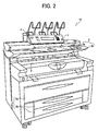
- FIG. 2 illustrates the outer appearance of an image forming apparatus 10 according to an example embodiment of the present invention.
- the image forming apparatus 10 includes an operation control section 1, an original input section 2, a sheet storage section 3, a first output section 4, and a second output section 5.
- the operation control section 1 may be implemented by a control panel, which may include a plurality of keys, and/or a display panel 240 (FIG 5) that may function as a touch-panel screen.
- a control panel which may include a plurality of keys, and/or a display panel 240 (FIG 5) that may function as a touch-panel screen.
- any desired device having the function of communicating with a user such as a speaker, a buzzer, or a microphone, may be provided.
- a user may instruct the image forming apparatus 10 to perform various kinds of operation including scanning, printing, copying, or faxing.
- the original input section 2 is provided, which may include an original guide 2a, which may be optionally provided, and an original table 2b. As illustrated below referring to FIG. 5, the user may place the original onto the original table 2b. Further, as described below referring to FIG. 4, the original input section 2 may detect the width of the original (“the original width") using one or more sensors.
- the original width corresponds to the length of the original in the main scanning direction
- the original length corresponds to the length of the original in the sub-scanning direction.
- the sheet storage section 3, which is provided at a lower portion of the image forming apparatus 10, may include a roll paper tray 3a, and/or one or more cut paper cassettes 3b.
- the roll paper tray 3a includes a first paper holder capable of holding a paper roll having the width of 841 mm, and a second paper holder capable of holding another paper roll having the width of 728 mm.
- the cut paper cassettes 3b include a first paper cassette capable of storing a stack of cut paper having the A2 size, and a second paper cassette capable of storing another stack of cut paper having the A3 size.
- the width of paper roll or the size of cut paper may be changed according to the user preference.
- the first output section 4, which is provided at an upper portion of the image forming apparatus 10, may hold a recording sheet being discharged from the image forming apparatus 10.
- the second output section 5, which is provided between the original input section 2 and the sheet storage section 3, may hold a recording sheet being discharged from the image forming apparatus 10.
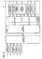
- FIG. 3 illustrates an example electrical structure of the image forming apparatus 10 shown in FIG. 2.
- the image forming apparatus 10 includes a system controller 11 and an engine 12, which are coupled with each other through an interface, such as a bus.
- the image forming apparatus 10 may further include a user interface 24, a copy application 25, a scanner application 26, a printer application 27, and a facsimile ("fax") application 28.
- the image forming apparatus 10 may include one or more applications, for example, a web application that allows the image forming apparatus 10 to communicate with one or more apparatuses via a network, such as the Internet.
- the system controller 11 is coupled to each one of the copy application 25, the scanner application 26, the printer application 27, and the fax application 28, via an interface, such as a bus.
- the system controller 11 may cause the image forming apparatus 10 to operate according to at least one of the copy application 25, the scanner application 26, the printer application 27, and the fax application 28.
- the copy application 25 may be executed to control an operation of copying.
- the scanner application 26 may be executed to control an operation of scanning.
- the printer application 27 may be executed to control an operation of printing.
- the fax application 28 may be executed to control an operation of faxing.
- the web application When the web application is provided as described above, the web application may be executed to control an operation of communicating via the network.
- the system controller 11 is further coupled to the user interface 24 via an interface.
- the user interface 24 may allow the user to communicate with the image forming apparatus 10 through the operation control section 1 of FIG. 2.
- the user may instruct the image forming apparatus 10 to perform at least one of the operations of copying, scanning, printing, and faxing, by selecting at least one of the plurality of keys or by selecting a desired portion of the display panel 240 (FIG 5).
- the system controller 11 may output a controller instruction to at least one of the applications 25, 26, 27, and 28, and the engine 12.
- the system controller 11 may output a controller instruction to the user interface 24, which requests the user interface 24 to notify the user of status information regarding the image forming apparatus 10.
- the user interface 24 causes the display panel 240 to display a message corresponding to the status information.
- the engine 12 includes an engine controller 13, a scanner 14, a plotter 15, an engine memory 16, an original width detector 17, an original length detector 18, a document feeder 19, an image processing device 20, a sheet transfer device 21, an image forming device 22, and a fixing device 23.
- the engine controller 13 may cause at least one of the devices in the engine 12 to perform at least one of the plurality of functions of copying, scanning, printing, and faxing, according to the controller instruction received from the system controller 11.
- the scanner 14 performs the function of scanning, using the original width detector 17, the original length detector 18, the document feeder 19, and/or the image processing device 20.
- the original width detector 17 obtains the original width, which may be detected by at least one of a plurality of sensors provided in the original input section 2.
- the original length detector 18 obtains the original length, for example, by counting a time period it takes for the scanner 14 to scan the entire portion of the original.
- the document feeder 19 feeds the original in the sub-scanning direction.
- the image processing device 20 may apply various image processing to image data read from the original. In operation, the scanner 14 reads an original into image data, by scanning the original, which is fed in the sub-scanning direction by the document feeder 19, in the main scanning direction with reference at a reading reference point.
- the reading reference point corresponds to the center Co of the original table 2b ("the original table center Co") shown in FIG. 4.
- the image data read from the original may be further processed by the image processing device 20.
- the processed, or unprocessed, image data may be stored in a memory, such as the engine memory 16.
- the plotter 15 performs the function of printing, using the image processing device 20, the sheet transfer device 21, the image forming device 22, and/or the fixing device 23.
- the image processing device 20 may apply various image processing to image data to be printed.
- the sheet transfer device 21 transfers a recording sheet.
- the image forming device 22 forms an image on the recording sheet according to the image data.
- the image forming device 22 may form an electrostatic latent image based on the image data, develops the latent image into a toner image, and transfers the toner image onto the recording sheet.
- the fixing device 23 fixes the image onto the recording sheet.
- the plotter 15 forms an image according to image data onto a recording sheet with reference at a writing reference point.
- the writing reference point corresponds to a side of the recording sheet.
- the engine controller 13 may cause the scanner 14 and the plotter 15 to together perform the function of printing.
- the scanner 14 may read an original into image data with reference at the reading reference point.
- the plotter 15 forms an image on a recording sheet according to the image data with reference at the writing reference point.
- the engine memory 16 may store various data including, for example, information input by the user through the user interface 24, which may be sent to the engine 12 through the system controller 11.
- the original input section 2 includes the plurality of sensors, which may be collectively referred to as the original width detector 17 (FIG. 3), at its inner portion.
- the original width detector 17 may be implemented by an optical sensor, for example, a reflective photodeflector or a transmissive photointerrupter.
- eleven sensors SN1 to SN11 are arranged along the main scanning direction from one end to the other end.
- the number of sensors may not be limited to this example.
- the original width may be detected when the original is placed on the original table 2b, for example, as illustrated in FIG. 5. Further, in this example, the sensor SN5 of FIG.
- the original width may be detected using the original width detector 17.
- the original width may be detected based on the Japanese Industrial Standards, such as JIS-B series or JIS-A series.
- the original width may be detected based on the architecture series or the engineering series. Further, in this example, the original width may be expressed in any desired unit, such as based on metrics system or inches. The detected original width may be used to determine the size of the recording sheet to be used, while considering information regarding the magnification ratio.
- the sensor SN1 which is provided at the position located 335 mm away from the original table center Co, detects whether the original has the width of 728 mm and determines whether to use the 728 mm width roller paper, the B I T paper, or B2T paper when magnification ratio is 100%.
- the sensor SN2 which is provided at the position located 225 mm away from the original table center Co, detects whether the original has the width of 515 mm and determines whether to use the 515 mm width roller paper, the B2T paper, or B3T paper when magnification ratio is 100%.
- the sensor SN3 which is provided at the position 170 mm away from the original table center Co, detects whether the original has the width of 364 mm and determines whether to use the 364 mm width roller paper, or the B3T paper when magnification ratio is 100%.
- the SN5 which is provided at the position located 10 mm away from the original table center Co, detects whether the original has the width of 210 mm and determines whether to use the 210 mm width roll paper or the A4T paper when magnification ratio is 100%.
- the sensor SN6 which is provided at the position located 140 mm away from the original table center Co, detects whether the original has the width of 297 mm and determines to use the 297 mm width roll paper or the A3 T paper when magnification ratio is 100%.
- the sensor SN7 which is provided at the position located 195 mm away from the original table center Co, detects whether the original has the width of 420 mm and determines to use the 420 mm width roll paper, the A2T paper, or the A3T paper when magnification ratio is 100%.
- the sensor SN8 which is provided at the position located 280 mm away from the original table center Co, detects whether the original has the width of 594 mm and determines to use the 594 mm width roll paper, the A1T paper, or the A2T paper when magnification ratio is 100%.
- the sensor SN9 which is provided at the position located 320 mm away from the original table center C, detects whether the original has the width of 660 mm, and determines to use the 660 mm width roll paper when magnification ratio is 100%.
- the sensor SN10 which is provided at the position located 400 mm away from the original table center Co, detects whether the original has the width of 841 mm and determines to use the 841 mm width paper roller, the A0T paper, or the A1T paper when magnification ratio is 100%.
- the sensor SN11 which is provided at the position located 444.5 mm away from the original table center Co, determines a maximum reading width of the scanner 14 or the image forming apparatus 10.
- the maximum reading width may be defined as the maximum width that the scanner 14, or the image forming apparatus 10, is capable of reading. In this example, the maximum reading width is set to 914 mm. However, the maximum reading width may be specific to each image reading device or image forming apparatus.
- the position of each sensor or the detectable size of each sensor may be specific to each image reading device or image forming apparatus.
- all of the sensors SN1 to SN11, except for the sensor SN5 are arranged along a straight line perpendicular to the sheet feeding direction indicated by the arrow shown in FIG. 5.
- the sensor SN5 which has the function of detecting the original being placed on the original table 2b, is arranged at the location upperstream in the sheet transfer direction.
- the sensor SN5 is provided at the location 179 mm away from the locations of the other sensors in the sheet transfer direction toward the user.
- the original width detector 17 While the original width may be detected by the original width detector 17, there are some example cases in which the original width may not be correctly detected. In one example, when the center of the original is not placed at the original table center Co, which functions as the reading reference point of the scanner 14, the original width may not be correctly detected. In another example, when the original width is different from any one of the original widths detectable by one of the sensors SN1 to SN11, the original width may not be correctly detected. When the original width is not correctly detected, the scanner 14 may not be able to scan the entire portion of the original since the scanner 14 reads, by default, the original at an image reading width determined based on the detected original width.
- the image reading width of the scanner 14 may be set to the maximum reading width, by default.
- the scanner 14 is able to scan the entire portion of the original, even when the center of the original is not placed at the original table center Co or even when the original has the custom size.
- the image reading width of the scanner 14 may be set to the maximum reading width, by default according to a user preference.
- the user preference may be input by the user through the operation control section 1 (FIG. 2).
- the user preference may be input by the user through an input device, such as a mouse or a keyboard, provided at the user site.
- the image reading width of the scanner 14 may be set to the maximum reading width according to a user instruction for setting the image reading width to the maximum reading width. For example, when printing the custom size original, the user may input the user instruction, which causes the image forming apparatus 10 to read the original at the maximum reading width. Upon receiving the user instruction, the image reading width of the scanner 14 may be changed, from the default image reading width, to the maximum reading width.
- the default image reading width may be determined based on the detected original width.
- the default image reading width may be set substantially equal to the detected original width.
- the default image reading width may be determined based on a recording sheet size, if the recording sheet size is known.
- the work required by the scanner 14, including the memory space used for storing the image data, may be reduced when compared with the above-described case of reading the original at the maximum reading width by default.
- the user instruction may be input by the user through the operation control section 1 (FIG. 2).
- the user instruction may be input by the user through the input device, such as the mouse or the keyboard, provided at the user site.
- the image data may not be formed onto the right position on the recording sheet
- the image forming apparatus 10 may be provided with the function of adjusting the position of the image data in the main scanning direction relative to the reference point such that the center of the image data to be formed on the recording sheet matches the center of the recording sheet.
- the position of the image data may be adjusted by shifting the position of a reading start point of the image data read from the original relative to the reference point in the main scanning direction.
- the position of the image data may be adjusted by shifting the position of the image data read from the original relative to the reference point in the main scanning direction.
- data may be deleted from the image data or added to the image data.
- FIG. 6 operation of copying an original, performed by the image forming apparatus 10, is explained according to an example embodiment of the present invention.
- the operation of FIG. 6 may be performed by the engine controller 13 of FIG 3, according to a user instruction received through the system controller 11 of FIG 3.
- the user instruction may be received by the user through the operation control section 1 (FIG. 2), including the display panel 240 (FIG 5).
- the user instruction may be received by the user through an input device provided at the user site, when the image forming apparatus 10 is connected to the network.
- the image forming apparatus 10 displays the screen illustrated in FIG. 7 on the display panel 240, when the power is turned on or the copy function is selected.
- the "Auto Paper Select" key is selected by default.
- the image forming apparatus 10 automatically selects a recording sheet for copying based on the magnification ratio and/or the original width detected by the original width detector 17.
- the user may disable this auto paper select function, by selecting at least one of the "tray” keys 24a, or selecting the "Bypass" key.
- the auto paper select function is set by default. However, the user may change the default settings, using the operation control section 1.
- the screen displayed by the display panel 240 for example, information indicated by the "tray" keys 24a, may be changed according to the recording sheets stored in the image forming apparatus 10.
- the "Full Size” key is selected by default.
- the image forming apparatus 10 sets the magnification ratio to 100 %.
- the user may change the magnification ratio, by selecting any one of the "Auto Reduce/Enlarge (R/E)" key, the “User Auto R/E” key, or the “Reduce/Enlarge” key.
- S101 determines whether the original is detected by the sensor SN5. As described above, the engine controller 13 receives the detection signal from the sensor SN5 when the original is detected by the sensor SN5. If the original is detected ("YES" at S101), the operation proceeds to Step S 102. Otherwise (''NO'' at S101), the operation repeats Step S101. In this example, the center of the original may not be placed at the original table center Co, as long as the original is placed at a portion on the original table 2b detectable by the sensor SN5.
- S 102 detects the original width using the original width detector 17. At this time, the detected original width may be stored in the engine memory 16.
- the engine controller 13 may send a request to the system controller 11 to notify the user when the original width is not detectable by the original width detector 17. For example, when the detected original width does not match the width of any one of the recording sheets stored in the image forming apparatus 10, the engine controller 13 may send a request to disable the auto paper select function. Accordingly, the system controller 11 may cause the display panel 240 to change the appearance of the "Auto Paper Select" key to indicate that the auto paper selection function is disabled. Alternatively, the display panel 240 may display an error message, which requests the user to select one of the "tray" keys 24a or replace the tray with a suitable recording sheet.
- the reading settings information which may be input by the user through the operation control section 1, may be input to the system controller 11, through the user interface 24.
- the system controller 11 sends the reading settings information to the engine controller 13.
- the engine controller 13 may store the reading settings information in the engine memory 16.
- the user may specify the recording sheet for use, by selecting at least one of the "tray" keys 24a displayed on the display panel 240.
- Information regarding the recording sheet (“the recording sheet information"), such as the size or width of the recording sheet, may be sent to the engine 12 through the system controller 11.
- the recording sheet information may be stored in the engine memory 16.
- the user may select at least one of the "tray" keys 24a.
- the user may specify whether to reduce or enlarge the size of the original, by selecting at least one of the "Auto R/E” key, the "User Auto R/E” key and the “Reduce/Enlarge” key, which are displayed on the display panel 240.
- Information regarding the magnification ratio between the original image and the copied image (“the magnification information''), such as the magnification ratio, may be sent to the engine 12 through the system controller 11. At this time, the magnification information may be stored in the engine memory 16.
- the user may instruct the image forming apparatus 10 to set the image reading width to the maximum reading width.
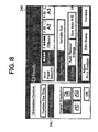
- the user may select the "Orientation/Custom" key 24b shown in FIG. 7.
- the display panel 240 changes the screen shown in FIG. 7 to the screen shown in FIG. 8.
- the user may further select the "Wide Scan” key 24c, for example, when the user desires to change the image reading width of the scanner 14 to the maximum reading width.
- the auto paper select function is disabled such that the "Auto Paper Select” key is not highlighted. Instead, one of the "tray” keys 24a may be highlighted, for example, the first tray key corresponding to the 841 mm width roll paper as illustrated in FIG. 8.
- the "Synchro Cut” key may be selected by default.
- the image forming apparatus 10 cuts the roll paper at the length determined based on the original length detected by the original length detector 18. The user may disable this function, for example, by selecting the "Variable Cut” key.
- the image forming apparatus 10 cuts the roll paper at the length specified by the user.
- the "Original Orientation” key indicating the orientation of the original being fed may be automatically highlighted as illustrated in FIG. 8.
- the engine controller 13 receives, from the system controller 11, a request for information regarding the original size ("the size information"), which may be defined by the original width and the original length.
- the engine controller 13 determines whether the user instruction for setting the image reading width to the maximum reading width is received from the user through the system controller 11 at S 103. If the user instruction for the maximum reading width is not received, i.e., the "Wide Scan" key 24c is not selected at S103 ('"NO” at S105), the operation proceeds to S106a. If the user instruction for the maximum reading width is received, i.e., the "Wide Scan" key 24c is selected at S 103 ("YES" at S105), the operation proceeds to S 106b.
- the engine controller 13 sets the image reading width, which may be considered the same as the original width in this example, to be substantially equal to the detected original width obtained at S102.
- the engine controller 13 sets the image reading width, which may be considered the same as the original width in this example, to be equal to the maximum reading width according to the user instruction received at S103.
- the engine controller 13 sends the size information to the system controller 11 in response to the request received at S 104. For example, when the image reading width is set based on the detected original width at S106a, the engine controller 13 sends the detected original width as the original width. In another example, when the image reading width is set equal to the maximum reading width at S106b, the engine controller 13 sends the maximum reading width as the original width. Further, at this time, the original length may be sent to the system controller 11, if the original length is input at S 103, for example, by selecting the cut paper from the "tray" keys 24a. The size information sent to the system controller 13 at this time may be changed or updated in the step described below.
- the engine controller 13 receives a controller instruction for starting reading operation, from the system controller 11.
- the engine controller 13 sets the reading settings of the scanner 14 according to various information obtained in the previous steps, including the reading settings information obtained at S 103 or information regarding the detected original width obtained at S102.
- the reading settings may be set such that the position of the image data can be adjusted after the image data is read from the original, for example, as described below referring to FIG. 9.
- the position of the image data may be adjusted by shifting the position of the reading start point relative to the reference point, for example, as described below referring to FIGS. 9 and 10.
- the position of the image data may be adjusted by shifting the position of the image data read from the original relative to the reference point, for example, as described below referring to FIGS. 9 and 11.
- the engine controller 13 causes the scanner 14 to start reading the original according to the reading settings set at S109.
- the document feeder 19 may start feeding the original in the sheet transfer direction, i.e., the sub-scanning direction.
- the original length detector 18 may start counting a time period it takes the scanner 14 to scan the entire portion of the original. The counted time period may be used to determine the original length, when the roll paper is selected at S 103.
- the engine controller 13 causes the document feeder 19 to end feeding.
- the original length detector 18 may end counting the time period.
- the engine controller 13 sends the size information to the system controller 11.
- the original length detector 18 may output information regarding the detected original length, for example, when the roll paper is selected at S103.
- the engine controller 13 causes the scanner 14 to end reading to complete reading operation.
- the image data read by the scanner 14, which may be processed by the image processing device 20 (FIG. 3) according to the reading settings set at S109, may be stored, for example, in the engine memory 16.
- the engine controller 13 may further cause the plotter 15 to form an image according to the image data on the recording sheet, and the operation ends.
- scanning and printing operations are both performed by the image forming apparatus 10 to complete copying.
- the printing operation may be performed by another image forming apparatus, which may be coupled to the image forming apparatus 10 via the network.
- S114 of FIG 6 is not performed by the image forming apparatus 10.
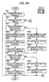
- Step S201 determines whether the reading settings are changed, for example, by comparing the reading settings information received by the engine controller 13 at S103 of FIG 6 with reading setting information stored in the engine memory 16. If the image reading settings are not changed ("NO" at S201), the operation ends to proceed to S110 of FIG. 6. In this manner, the overall processing speed of the image forming apparatus 10 may be reduced. If the image reading settings are changed ("YES" at S201), the operation proceeds to Step S202.
- the reading settings information may include, for example, information whether the user instruction for setting the image reading width to the maximum reading width is received, the magnification information, and/or the recording sheet information.
- S202 determines whether the image reading width is set to the maximum reading width. If the image reading width is set to the maximum reading width ("YES" at S202), the operation proceeds to S203. Otherwise (“NO" at Step S202), the operation proceeds to S204c, S205c, S206c, S208c, and S209c.
- the engine controller 13 defines a position of the reference point based on the image data width.
- the image data width may be obtained by multiplying the detected original width with the magnification ratio in the main scanning direction.
- the engine controller 13 determines whether to shift the position of the reading start point relative to the reference point. Since the image reading width is not set to the maximum reading width, at S205c, the engine controller 13 sets the amount of shifting the position of the reading start point to 0. For the same reason, at S206c, the engine controller 13 sets the amount of data to be deleted from the image data to 0. At S208c, the engine controller 13 determines whether to shift the position of the image data relative to the reference point.
- the engine controller 13 sets the amount of shifting the position of the image data to 0. For the same reason, at S209c, the engine controller 13 sets the amount of data to be added to the image data to 0, and the operation ends.
- the engine controller 13 determines whether the image data width is greater than the recording sheet width.
- the image data width may be determined by the multiplication of the maximum reading width and the magnification ratio in the main scanning direction.
- the maximum reading width is set to 914 mm.
- the magnification ratio in the main scanning direction may be obtained from the magnification information, which may be input as the reading settings information.
- the recording sheet width may be obtained from the recording sheet information, which may be input as the reading settings information. If the image data width is greater than the recording sheet width ("YES" at S203), the operation proceeds to S204a, S205a, and S206a. Otherwise (“NO" at S203), the operation proceeds to S204b, S205b, and S206b.
- the engine controller 13 When the image data width is greater than the recording sheet width, at S204a, the engine controller 13 defines a position of the reference point based on the recording sheet width. At S205a, the engine controller 13 determines whether to shift the position of the reading start point relative to the reference point. Since the image reading width is set to the maximum reading width, and the image data width is greater than the recording sheet width, the engine controller 13 determines to shift the position of the reading start point relative to the reference point, and calculates the amount of shifting using the reading settings information. At S206a, the engine controller 13 determines whether to delete data from the image data.
- the engine controller 13 calculates an amount of data to be deleted from the image data.
- the amount of data to be deleted is determined based on the amount of shifting obtained at S205a, and the operation proceeds to S207.
- the engine controller 13 defines a position of the reading reference point based on the image data width.
- the engine controller 13 determines whether to shift the position of the reading start point relative to the reference point. Since the image reading width is set to the maximum reading width, but the image data width is smaller than the recording sheet width, the engine controller 13 determines not to shift the position of the reading start point relative to the reference point, and sets the amount of shifting to 0. For the same reason, at S206b, the engine controller 13 sets the amount of data to be deleted from the image data to 0, and the operation proceeds to S207.
- S207 determines whether the image data width is smaller than the recording sheet width. If the image data width is smaller than the recording sheet width ("YES" at S207), the operation proceeds to S208b and S209b. If the image data width is greater than the recording sheet width (''NO" at S207), the operation proceeds to S208a and S209a.
- the engine controller 13 determines to shift the position of the image data read from the original relative to the reference point in the main scanning direction, and calculates the amount of shifting using the reading settings information.
- the engine controller 13 calculates an amount of data to be added to the image data, and the operation ends. The amount of data to be added is determined based on the amount of shifting the position of the image data.
- the engine controller 13 determines not to shift the position of the image data read from the original relative to the reference point, and sets the amount of shifting to 0.
- the engine controller 13 sets the amount of data to be added to the image data to 0, and the operation ends.
- the image reading width of the image forming apparatus 10 may be set to the maximum reading width, by default. In such case, the steps including S202, S204c, 205c, 206c, 208c, and 209c may not be performed.
- the image forming apparatus 10 is capable of processing the image data such that the image data is formed with reference at a side of the recording sheet, when the user instruction for setting the image reading width to the maximum reading width is not received. In this manner, the user is able to easily change the appearance of the resultant image, between the image formed with reference at the center of the recording sheet and the image formed width reference at the side of the recording sheet.
- adjusting the position of the image data is explained, when the image data width is greater than the recording sheet width, according to an example embodiment of the present invention. Further, in this example, the user instruction for setting the image reading width to the maximum reading width has been input.
- the original Do is placed on the original table 2b such that the center of the original Do corresponds to the original table center Co, which functions as the reading reference point Ro of the scanner 14.
- the original Do has the original width Wo.
- the recording sheet width Ws of the recording sheet S is specified to be smaller than the original width Wo, according to the user instruction.
- the image reading width of the scanner 14 is set to the maximum reading width Wm, according to the user instruction.
- the image reading width is set to the maximum reading width Wm
- the image data D1 which corresponds to the full size image of the original Do, has the width Wm.
- the dark portion of the image data D1 indicates data that has been added to the original image when the original Do is read at the maximum reading width.
- the image data D 1 is formed on the recording sheet S with reference at a side of the recording sheet S, which functions as the writing reference point Rs. Since the recording sheet width Ws is smaller than the original width Wo, the original width Wo is made smaller by the magnification ratio M than the recording sheet width Ws. As a result, the reduced size image data D2 is generated.
- the image data D2 has the width Wm * M, which is greater than the recording sheet width Ws, a portion of the image data D2, including a portion of the image read from the original Do, may not fit on the recording sheet S. Further, since the image data D2 is formed on the recording sheet with reference at the side of the recording sheet S, the center Ci of the image data D2 does not correspond to the center Cs of the recording sheet S, or the original table center Co.
- the image forming apparatus 10 adjusts the position of the image data D2, for example, as described above referring to FZG. 9.
- the position of the image data D2 is adjusted by shifting the position of the reading start point, which originally matches the position of the writing reference point Rs, in the direction indicated by the arrow shown in FIG. 10.
- the position of the writing reference point Rs may be defined based on the recording sheet width Ws.
- the amount of shifting the position of the reading start point is calculated as the difference between the position of the image center Ci and the position of the recording sheet center Cs. Accordingly, the position of the image center Ci matches the position of the recording sheet center Cs, as illustrated in FIG 10, when the image data D2 is formed on the recording sheet S with reference at the writing reference point Rs.
- the image data width Wm*M of the image data D2 is greater than the recording sheet width Ws, a portion of the image data D2 may be deleted.
- the amount of data to be deleted from the image data D2 may be determined based on the amount of shifting the position of the reading start point, that is, the difference between the image center Ci and the recording sheet center Cs.
- adjusting the position of the image data is explained, when the image data width is smaller than the recording sheet width, according to an example embodiment of the present invention. Further, in this example, the user instruction for setting the image reading width to the maximum reading width has been input.
- the original Do is placed on the original table 2b such that the center of the original Do corresponds to the original table center Co, which functions as the reading reference point Ro of the scanner 14.
- the original Do has the original width Wo.
- the recording sheet width Ws of the recording sheet S is specified to be greater than the original width Wo, according to the user instruction.
- the image reading width of the scanner 14 is set to the maximum reading width Wm, according to the user instruction.
- the image reading width is set to the maximum reading width Wm
- the image data D1 which corresponds to the full size image of the original Do, has the maximum reading width Wm.
- the dark portion of the image data D1 indicates data that has been added to the original image when the original Do is read at the maximum reading width. Further, in this example, the image data D1 is reduced by the magnification ratio M to generate the image data D2.
- the center Ci of the image data D2 does not correspond to the center Cs of the recording sheet S, or the original table center Co.
- the image forming apparatus 10 adjusts the position of the image data D2, for example, as described above referring to FIG 9.
- the position of the image data D2 is adjusted by shifting the position of the image data D2 from the reading start point, which matches the position of the writing reference point Rs, in the direction indicated by the arrow shown in FIG. 10.
- the position of the writing reference point Rs may be defined based on the image data width Wm*M.
- the amount of shfiting the position of the image data is calculated as the difference between the position of the image center Ci, and the position of the recording sheet center Cs. Accordingly, the position of the image center Ci matches the position of the recording sheet center Cs, as illustrated in FIG. 11, when the image data D2 is formed on the recording sheet S with reference at the writing reference point Rs.
- the image data width Wm*M of the image data D2 is smaller than the recording sheet width Ws
- data may be added to the image data D2.
- the amount of data to be added to the image data D2 may be determined based on the amount of shifting the position of the image data, that is, the difference between the position of the image center Ci and the position of the recording sheet center Cs. By adding the data having the background color, quality of the copied image may increase.
- the image data D1 is reduced by the magnification ratio of M to generate the image data D2.
- the image data D1 may not be reduced.
- the position of the image data D1 may be shifted in a substantially manner as described above referring to FIG. 10.
- any one of the above-described and other methods of the present invention may be embodied in the form of a computer program stored in any desired kind of storage medium.
- storage mediums include, but are not limited to, flexible disk, hard disk, optical discs, magneto-optical discs, magnetic tapes, involatile memory cards, ROM (read-only-memor), etc.
- any one of the above-described and other methods of the present invention may be implemented by ASIC, prepared by interconnecting an appropriate network of conventional component circuits or by a combination thereof with one or more conventional general purpose microprocessors and/or signal processors programmed accordingly.
Landscapes
- Engineering & Computer Science (AREA)
- Multimedia (AREA)
- Signal Processing (AREA)
- Facsimiles In General (AREA)
- Control Or Security For Electrophotography (AREA)
- Facsimile Scanning Arrangements (AREA)
- Optical Systems Of Projection Type Copiers (AREA)
- Image Input (AREA)
Abstract
Description
- Example embodiments of the present invention relate generally to an image reading device, and an image forming apparatus provided with the image reading device.
- An image forming apparatus is usually provided with an image reading device for reading an original into image data, and an image forming device for forming an image on a recording sheet according to the image data. In order to make a copy of the original, the image reading device automatically detects a size of the original with reference at a reading reference point, and reads the original by scanning an image reading area that matches the detected size of the original. Further, the image forming apparatus may automatically select a recording sheet that matches the detected size of the original. The image forming device forms the image of the original on the recording sheet with reference at a writing reference point.
- However, there may be some situations in which the image reading device fails to correctly read the original into image data. In one example, when the original has a custom size not detectable by the image forming apparatus, the size of the original may be detected to be smaller than the actual size of the original. In such case, a portion of the original may not be read, since the size of the image reading area may be set smaller than the actual original size. In another example, when the original is not placed at the right position relative to the reading reference point, the size of the original may be detected to be smaller than the actual size of the original such that a portion of the original may not be read.
- In addition, when the reading reference point differs from the writing reference point, there may be some situations in which the image forming device fails to correctly form the image according to the image data onto the recording sheet. In one example, when the original size is different from the size of the recording sheet, the image generated according to the image data may not be formed onto the right position of the recording sheet. As illustrated in FIG. 1, the image reading device may read the original with reference at the center Co of an original table. In this example, the original is placed on the original table such that the center of the original corresponds to the center Co of the original table. Thus, the center Ci of the image data read from the original, corresponds to the center Co of the original table. The image forming device may form the image according to the image data with reference at a side of the recording sheet. When the size of the recording sheet is different from the size of the original, the center Ci of the image data to be formed on the recording sheet may be different from the center Cs of the recording sheet, which corresponds to the center Co of the original table. When the size of the original is greater than the size of the recording sheet, a portion of the original may not be formed on the recording sheet.
- Example embodiments of the present invention include an image reading device capable of reading an original into image data by scanning the original in the main scanning direction at an image reading width while the original is being fed in a sub-scanning direction. When a user instruction for setting the image reading width to the maximum reading width is input, the image reading width of the image reading device is set to a maximum reading width.
- For example, the image reading device includes reading means for reading an original into image data by scanning the original in the main scanning direction at an image reading width while the original is being fed in a sub-scanning direction; and setting means for setting the image reading width to a maximum reading width of the reading means when reading settings information comprising a user instruction for setting the image reading width to the maximum reading width is input. In one example, the reading means may correspond to a scanner of the image reading device that reads the original being fed by a document feeder. The setting means may correspond to an engine including an engine controller.
- In this example, the image reading device may be provided with holding means for holding the original to be read by the reading means such that the reading means may read the original with reference at the center of the holding means. The holding means may correspond to a document table. Further, in this example, the image reading device may be provided with image forming means for forming an image of the original according to the image data on a recording sheet with reference at one side of the recording sheet.
- In addition to the user instruction for setting the image reading width to the maximum reading width, the user may input at least one of: recording sheet information Including information indicating a width of a recording sheet on which the image data is to be formed; and magnification information including information indicating a magnification ratio between the size of image data read from the original and the size of the image data to be formed on the recording sheet. The reading settings information may be input through a user interface, for example, using an operation control section provided with the image reading device or an input device coupled to the image reading device.
- Further, when the user instruction for setting the image reading width to the maximum reading width is input, a position of the image data read from the original may be adjusted relative to a reference point such that the center of the image data to be formed on the recording sheet matches the center of the recording sheet, for example, based on whether a width of the image data to be formed on the recording sheet is greater than the width of the recording sheet. For example, the width of the image data is obtained by multiplying the image reading width of the image reader with the magnification ratio obtained from the magnification information. The position of the image data may be adjusted, for example, by the setting means, which may correspond to the engine including the engine controller, by performing at least one of the following operations.
- In one example operation, the setting means may define a position of the reference point using the reading settings information based on whether a width of the image data to be formed on the recording sheet is greater than the width of the recording sheet.
- In another example operation, the image reading device may be provided with first shifting means for shifting a position of a reading start point of the image data relative to the defined position of the reference point in the main scanning direction, when the width of the image data to be formed on the recording sheet is greater than the width of the recording sheet. In this example, the amount of shifting the position of the reading start point is determined based on the reading settings information. The first shifting means may correspond to the engine including the engine controller and an image processing device.
- In another example operation, the image reading device may be provided with second shifting means for shifting a position of the image data relative to the defined position of the reference point in the main scanning direction, when the width of the image data to be formed on the recording sheet is smaller than the width of the recording sheet. In this example, an amount of shifting the position of the image data is determined based on the reading settings information. The second shifting means may correspond to the engine including the engine controller and an image processing device.
- In another example operation, the image reading device may be provided with means for adding or deleting data to or from the image data by an amount determined based on the reading settings information. Preferably, the amount of adding or deleting may be determined based on the amount of shifting determined by the first or second shifting means.
- Further, the image reading device may be provided with first detecting means for detecting the width of the original in the main scanning direction to generate a detected original width. The image reading width of the image reader is set, by the setting means, based on the detected original width when the user instruction for setting the image reading width to the maximum reading width is not included in the reading settings information. The first detecting means may correspond to an original width detector.
- Further, the image reading device may be provided with second detecting means for detecting the length of the original in the sub-scanning direction to generate a detected original length. An image reading length of the image reader is set, by the setting means, to the detected original length. The second detecting means may correspond to an original length detector.
- Any one of the image reading device described herein may be incorporated in any desired image forming apparatus, together with an image forming device for forming an image of the original according to the image data on the recording sheet and a user interface for inputting the reading settings information.
- A more complete appreciation of the disclosure and many of the attendant advantages thereof will be readily obtained as the same becomes better understood by reference to the following detailed description when considered in connection with the accompanying drawings, wherein:
- FIG. 1 is an illustration for explaining reading an original into image data, and forming an image according to the image data on a recording sheet having a size different from the size of the original;
- FIG. 2 is a perspective view illustrating the outer appearance of an image forming apparatus according to an example embodiment of the present invention;
- FIG. 3 is a schematic block diagram illustrating an example electrical structure of the image forming apparatus shown in FIG. 2;
- FIG. 4 is an illustration for explaining the arrangement of a plurality of sensors provided in the image forming apparatus shown in FIG. 2;
- FIG. 5 is a perspective view illustrating a portion of the image forming apparatus shown in FIG. 2;
- FIG 6 is a flowchart illustrating operation of copying an original, performed by the image forming apparatus shown in FIG. 2, according to an example embodiment of the present invention;
- FIG. 7 is a plan view illustrating an example screen displayed by a display panel of the image forming apparatus shown in FIG. 2, when the operation of FIG 6 is performed;
- FIG 8 is a plan view illustrating a portion of an example screen displayed by the display panel of the image forming apparatus shown in FIG. 2, when the operation of FIG. 6 is performed;
- FIG. 9 is a flowchart illustrating operation of adjusting a position of image data, performed by the image forming apparatus shown in FIG. 2, according to an example embodiment of the present invention;
- FIG. 10 is an illustration for adjusting a position of image data when copying an original onto a recording sheet having a width greater than the width of the original, according to an example embodiment of the present invention; and
- FIG. 11 is an illustration for adjusting a position of image data when copying an original onto a recording sheet having a width smaller than the width of the original, according to an example embodiment of the present invention.
- In describing the example embodiments illustrated in the drawings, specific terminology is employed for clarity. However, the disclosure of this patent specification is not intended to be limited to the specific terminology selected and it is to be understood that each specific element includes all technical equivalents that operate in a similar manner. For example, the singular forms "a", "an" and "the" are intended to include the plural forms as well, unless the context clearly indicates otherwise.
- Referring now to the drawings, wherein like reference numerals designate identical or corresponding parts throughout the several views, FIG. 2 illustrates the outer appearance of an
image forming apparatus 10 according to an example embodiment of the present invention. As illustrated in FIG. 2, theimage forming apparatus 10 includes anoperation control section 1, anoriginal input section 2, asheet storage section 3, a first output section 4, and asecond output section 5. - The
operation control section 1 may be implemented by a control panel, which may include a plurality of keys, and/or a display panel 240 (FIG 5) that may function as a touch-panel screen. In addition, any desired device having the function of communicating with a user, such as a speaker, a buzzer, or a microphone, may be provided. Using theoperation control section 1, a user may instruct theimage forming apparatus 10 to perform various kinds of operation including scanning, printing, copying, or faxing. - Below the
operation control section 1, theoriginal input section 2 is provided, which may include anoriginal guide 2a, which may be optionally provided, and an original table 2b. As illustrated below referring to FIG. 5, the user may place the original onto the original table 2b. Further, as described below referring to FIG. 4, theoriginal input section 2 may detect the width of the original ("the original width") using one or more sensors. In this specification, the original width corresponds to the length of the original in the main scanning direction, while the original length corresponds to the length of the original in the sub-scanning direction. - Referring back to FIG 2, the
sheet storage section 3, which is provided at a lower portion of theimage forming apparatus 10, may include aroll paper tray 3a, and/or one or morecut paper cassettes 3b. In this example, theroll paper tray 3a includes a first paper holder capable of holding a paper roll having the width of 841 mm, and a second paper holder capable of holding another paper roll having the width of 728 mm. In this example, thecut paper cassettes 3b include a first paper cassette capable of storing a stack of cut paper having the A2 size, and a second paper cassette capable of storing another stack of cut paper having the A3 size. However, the width of paper roll or the size of cut paper may be changed according to the user preference. - The first output section 4, which is provided at an upper portion of the
image forming apparatus 10, may hold a recording sheet being discharged from theimage forming apparatus 10. Thesecond output section 5, which is provided between theoriginal input section 2 and thesheet storage section 3, may hold a recording sheet being discharged from theimage forming apparatus 10. - FIG. 3 illustrates an example electrical structure of the
image forming apparatus 10 shown in FIG. 2. Theimage forming apparatus 10 includes asystem controller 11 and anengine 12, which are coupled with each other through an interface, such as a bus. Theimage forming apparatus 10 may further include auser interface 24, acopy application 25, ascanner application 26, aprinter application 27, and a facsimile ("fax")application 28. In addition to theapplications image forming apparatus 10 may include one or more applications, for example, a web application that allows theimage forming apparatus 10 to communicate with one or more apparatuses via a network, such as the Internet. - The
system controller 11 is coupled to each one of thecopy application 25, thescanner application 26, theprinter application 27, and thefax application 28, via an interface, such as a bus. Thesystem controller 11 may cause theimage forming apparatus 10 to operate according to at least one of thecopy application 25, thescanner application 26, theprinter application 27, and thefax application 28. Thecopy application 25 may be executed to control an operation of copying. Thescanner application 26 may be executed to control an operation of scanning. Theprinter application 27 may be executed to control an operation of printing. Thefax application 28 may be executed to control an operation of faxing. When the web application is provided as described above, the web application may be executed to control an operation of communicating via the network. - The
system controller 11 is further coupled to theuser interface 24 via an interface. Theuser interface 24 may allow the user to communicate with theimage forming apparatus 10 through theoperation control section 1 of FIG. 2. For example, the user may instruct theimage forming apparatus 10 to perform at least one of the operations of copying, scanning, printing, and faxing, by selecting at least one of the plurality of keys or by selecting a desired portion of the display panel 240 (FIG 5). Upon receiving the user instruction from theuser interface 24, thesystem controller 11 may output a controller instruction to at least one of theapplications engine 12. In another example, thesystem controller 11 may output a controller instruction to theuser interface 24, which requests theuser interface 24 to notify the user of status information regarding theimage forming apparatus 10. Upon receiving the controller instruction, theuser interface 24 causes thedisplay panel 240 to display a message corresponding to the status information. - The
engine 12 includes anengine controller 13, ascanner 14, a plotter 15, anengine memory 16, anoriginal width detector 17, anoriginal length detector 18, adocument feeder 19, animage processing device 20, asheet transfer device 21, animage forming device 22, and a fixingdevice 23. Theengine controller 13 may cause at least one of the devices in theengine 12 to perform at least one of the plurality of functions of copying, scanning, printing, and faxing, according to the controller instruction received from thesystem controller 11. - For example, the
scanner 14 performs the function of scanning, using theoriginal width detector 17, theoriginal length detector 18, thedocument feeder 19, and/or theimage processing device 20. Theoriginal width detector 17 obtains the original width, which may be detected by at least one of a plurality of sensors provided in theoriginal input section 2. Theoriginal length detector 18 obtains the original length, for example, by counting a time period it takes for thescanner 14 to scan the entire portion of the original. Thedocument feeder 19 feeds the original in the sub-scanning direction. Theimage processing device 20 may apply various image processing to image data read from the original. In operation, thescanner 14 reads an original into image data, by scanning the original, which is fed in the sub-scanning direction by thedocument feeder 19, in the main scanning direction with reference at a reading reference point. In this example, the reading reference point corresponds to the center Co of the original table 2b ("the original table center Co") shown in FIG. 4. The image data read from the original may be further processed by theimage processing device 20. The processed, or unprocessed, image data may be stored in a memory, such as theengine memory 16. - In another example, the plotter 15 performs the function of printing, using the
image processing device 20, thesheet transfer device 21, theimage forming device 22, and/or the fixingdevice 23. Theimage processing device 20 may apply various image processing to image data to be printed. Thesheet transfer device 21 transfers a recording sheet. Theimage forming device 22 forms an image on the recording sheet according to the image data. For example, theimage forming device 22 may form an electrostatic latent image based on the image data, develops the latent image into a toner image, and transfers the toner image onto the recording sheet. The fixingdevice 23 fixes the image onto the recording sheet. In operation, the plotter 15 forms an image according to image data onto a recording sheet with reference at a writing reference point. In this example, the writing reference point corresponds to a side of the recording sheet. - In another example, the
engine controller 13 may cause thescanner 14 and the plotter 15 to together perform the function of printing. In operation, thescanner 14 may read an original into image data with reference at the reading reference point. The plotter 15 forms an image on a recording sheet according to the image data with reference at the writing reference point. - The
engine memory 16 may store various data including, for example, information input by the user through theuser interface 24, which may be sent to theengine 12 through thesystem controller 11. - As described above referring to FIG. 2 or 3, the
original input section 2 includes the plurality of sensors, which may be collectively referred to as the original width detector 17 (FIG. 3), at its inner portion. Theoriginal width detector 17 may be implemented by an optical sensor, for example, a reflective photodeflector or a transmissive photointerrupter. In this example, as illustrated in FIG 4, eleven sensors SN1 to SN11 are arranged along the main scanning direction from one end to the other end. However, the number of sensors may not be limited to this example. Using thesensors SN 1 to SN11, the original width may be detected when the original is placed on the original table 2b, for example, as illustrated in FIG. 5. Further, in this example, the sensor SN5 of FIG. 4, which is provided near the original table center Co, is positioned at the location closer to the user in the sheet feeding direction indicated by the arrow in FIG. 5. The sensor SN5 outputs a detection signal when the sensor SN5 detects the original placed on the original table 2b. After the original is detected by the sensor SN5, the original width may be detected using theoriginal width detector 17. In one example, the original width may be detected based on the Japanese Industrial Standards, such as JIS-B series or JIS-A series. Alternatively, the original width may be detected based on the architecture series or the engineering series. Further, in this example, the original width may be expressed in any desired unit, such as based on metrics system or inches. The detected original width may be used to determine the size of the recording sheet to be used, while considering information regarding the magnification ratio. - For example, referring back to FIG. 4, the sensor SN1, which is provided at the position located 335 mm away from the original table center Co, detects whether the original has the width of 728 mm and determines whether to use the 728 mm width roller paper, the B I T paper, or B2T paper when magnification ratio is 100%. The sensor SN2, which is provided at the position located 225 mm away from the original table center Co, detects whether the original has the width of 515 mm and determines whether to use the 515 mm width roller paper, the B2T paper, or B3T paper when magnification ratio is 100%. The sensor SN3, which is provided at the position 170 mm away from the original table center Co, detects whether the original has the width of 364 mm and determines whether to use the 364 mm width roller paper, or the B3T paper when magnification ratio is 100%. The sensor SN4, which is provided at the
position 115 mm away from the original table center Co, detects whether the original has the width of 257 mm and determines whether to use the 257 mm width roll paper or the B4T paper when magnification ratio is 100%. The SN5, which is provided at the position located 10 mm away from the original table center Co, detects whether the original has the width of 210 mm and determines whether to use the 210 mm width roll paper or the A4T paper when magnification ratio is 100%. The sensor SN6, which is provided at the position located 140 mm away from the original table center Co, detects whether the original has the width of 297 mm and determines to use the 297 mm width roll paper or the A3 T paper when magnification ratio is 100%. The sensor SN7, which is provided at the position located 195 mm away from the original table center Co, detects whether the original has the width of 420 mm and determines to use the 420 mm width roll paper, the A2T paper, or the A3T paper when magnification ratio is 100%. The sensor SN8, which is provided at the position located 280 mm away from the original table center Co, detects whether the original has the width of 594 mm and determines to use the 594 mm width roll paper, the A1T paper, or the A2T paper when magnification ratio is 100%. The sensor SN9, which is provided at the position located 320 mm away from the original table center C, detects whether the original has the width of 660 mm, and determines to use the 660 mm width roll paper when magnification ratio is 100%. The sensor SN10, which is provided at the position located 400 mm away from the original table center Co, detects whether the original has the width of 841 mm and determines to use the 841 mm width paper roller, the A0T paper, or the A1T paper when magnification ratio is 100%. The sensor SN11, which is provided at the position located 444.5 mm away from the original table center Co, determines a maximum reading width of thescanner 14 or theimage forming apparatus 10. The maximum reading width may be defined as the maximum width that thescanner 14, or theimage forming apparatus 10, is capable of reading. In this example, the maximum reading width is set to 914 mm. However, the maximum reading width may be specific to each image reading device or image forming apparatus. The position of each sensor or the detectable size of each sensor may be specific to each image reading device or image forming apparatus. - Still referring to FIG. 4, all of the sensors SN1 to SN11, except for the sensor SN5, are arranged along a straight line perpendicular to the sheet feeding direction indicated by the arrow shown in FIG. 5. As described above referring to FIG 5, the sensor SN5, which has the function of detecting the original being placed on the original table 2b, is arranged at the location upperstream in the sheet transfer direction. In this example, as illustrated in FIG 4, the sensor SN5 is provided at the
location 179 mm away from the locations of the other sensors in the sheet transfer direction toward the user. - While the original width may be detected by the
original width detector 17, there are some example cases in which the original width may not be correctly detected. In one example, when the center of the original is not placed at the original table center Co, which functions as the reading reference point of thescanner 14, the original width may not be correctly detected. In another example, when the original width is different from any one of the original widths detectable by one of the sensors SN1 to SN11, the original width may not be correctly detected. When the original width is not correctly detected, thescanner 14 may not be able to scan the entire portion of the original since thescanner 14 reads, by default, the original at an image reading width determined based on the detected original width. - In view of the above, the image reading width of the
scanner 14 may be set to the maximum reading width, by default. Thescanner 14 is able to scan the entire portion of the original, even when the center of the original is not placed at the original table center Co or even when the original has the custom size. - Alternatively, the image reading width of the
scanner 14 may be set to the maximum reading width, by default according to a user preference. In one example, the user preference may be input by the user through the operation control section 1 (FIG. 2). In another example, when theimage forming apparatus 10 is connected to the network, such as a local area network (LAN) or the Internet, the user preference may be input by the user through an input device, such as a mouse or a keyboard, provided at the user site. - Alternatively, the image reading width of the
scanner 14 may be set to the maximum reading width according to a user instruction for setting the image reading width to the maximum reading width. For example, when printing the custom size original, the user may input the user instruction, which causes theimage forming apparatus 10 to read the original at the maximum reading width. Upon receiving the user instruction, the image reading width of thescanner 14 may be changed, from the default image reading width, to the maximum reading width. In this example, the default image reading width may be determined based on the detected original width. For example, the default image reading width may be set substantially equal to the detected original width. Alternatively, the default image reading width may be determined based on a recording sheet size, if the recording sheet size is known. Since the image reading width of thescanner 14 is changed to the maximum reading width only when the user desires, the work required by thescanner 14, including the memory space used for storing the image data, may be reduced when compared with the above-described case of reading the original at the maximum reading width by default. In this example, as described below referring to FIG. 6, the user instruction may be input by the user through the operation control section 1 (FIG. 2). Alternatively, when theimage forming apparatus 10 is connected to the network, such as the LAN or the Internet, the user instruction may be input by the user through the input device, such as the mouse or the keyboard, provided at the user site. - On the other hand, as illustrated in FIG. 1, when the reading reference point and the writing reference point are different from each other, the image data may not be formed onto the right position on the recording sheet
- In view of the above, the
image forming apparatus 10 may be provided with the function of adjusting the position of the image data in the main scanning direction relative to the reference point such that the center of the image data to be formed on the recording sheet matches the center of the recording sheet. In one example, the position of the image data may be adjusted by shifting the position of a reading start point of the image data read from the original relative to the reference point in the main scanning direction. In another example, the position of the image data may be adjusted by shifting the position of the image data read from the original relative to the reference point in the main scanning direction. In addition to adjusting the position of the image data, data may be deleted from the image data or added to the image data. - Referring now to FIG. 6, operation of copying an original, performed by the
image forming apparatus 10, is explained according to an example embodiment of the present invention. The operation of FIG. 6 may be performed by theengine controller 13 of FIG 3, according to a user instruction received through thesystem controller 11 of FIG 3. In this example, the user instruction may be received by the user through the operation control section 1 (FIG. 2), including the display panel 240 (FIG 5). Alternatively, the user instruction may be received by the user through an input device provided at the user site, when theimage forming apparatus 10 is connected to the network. - In this example, the
image forming apparatus 10 displays the screen illustrated in FIG. 7 on thedisplay panel 240, when the power is turned on or the copy function is selected. Referring to FIG. 7, the "Auto Paper Select" key is selected by default. When the "Auto Paper Select" key is selected, theimage forming apparatus 10 automatically selects a recording sheet for copying based on the magnification ratio and/or the original width detected by theoriginal width detector 17. The user may disable this auto paper select function, by selecting at least one of the "tray"keys 24a, or selecting the "Bypass" key. In this example, the auto paper select function is set by default. However, the user may change the default settings, using theoperation control section 1. The screen displayed by thedisplay panel 240, for example, information indicated by the "tray"keys 24a, may be changed according to the recording sheets stored in theimage forming apparatus 10. - Still referring to FIG. 7, in this example, the "Full Size" key is selected by default. When the "Full Size" key is selected, the
image forming apparatus 10 sets the magnification ratio to 100 %. However, the user may change the magnification ratio, by selecting any one of the "Auto Reduce/Enlarge (R/E)" key, the "User Auto R/E" key, or the "Reduce/Enlarge" key. - Referring back to FIG. 6, S101 determines whether the original is detected by the sensor SN5. As described above, the
engine controller 13 receives the detection signal from the sensor SN5 when the original is detected by the sensor SN5. If the original is detected ("YES" at S101), the operation proceeds to Step S 102. Otherwise (''NO'' at S101), the operation repeats Step S101. In this example, the center of the original may not be placed at the original table center Co, as long as the original is placed at a portion on the original table 2b detectable by the sensor SN5. - Further, at S102, the
engine controller 13 may send a request to thesystem controller 11 to notify the user when the original width is not detectable by theoriginal width detector 17. For example, when the detected original width does not match the width of any one of the recording sheets stored in theimage forming apparatus 10, theengine controller 13 may send a request to disable the auto paper select function. Accordingly, thesystem controller 11 may cause thedisplay panel 240 to change the appearance of the "Auto Paper Select" key to indicate that the auto paper selection function is disabled. Alternatively, thedisplay panel 240 may display an error message, which requests the user to select one of the "tray"keys 24a or replace the tray with a suitable recording sheet. - S103 inputs information regarding various reading settings ("the reading settings information"). In one example, the reading settings information, which may be input by the user through the
operation control section 1, may be input to thesystem controller 11, through theuser interface 24. Thesystem controller 11 sends the reading settings information to theengine controller 13. Theengine controller 13 may store the reading settings information in theengine memory 16. - In one example, the user may specify the recording sheet for use, by selecting at least one of the "tray"
keys 24a displayed on thedisplay panel 240. Information regarding the recording sheet ("the recording sheet information"), such as the size or width of the recording sheet, may be sent to theengine 12 through thesystem controller 11. At this time, the recording sheet information may be stored in theengine memory 16. For example, when the user desires to copy the original onto a recording sheet having a specific size or width, the user may select at least one of the "tray"keys 24a. - In another example, the user may specify whether to reduce or enlarge the size of the original, by selecting at least one of the "Auto R/E" key, the "User Auto R/E" key and the "Reduce/Enlarge" key, which are displayed on the
display panel 240. Information regarding the magnification ratio between the original image and the copied image ("the magnification information''), such as the magnification ratio, may be sent to theengine 12 through thesystem controller 11. At this time, the magnification information may be stored in theengine memory 16. - In another example, the user may instruct the
image forming apparatus 10 to set the image reading width to the maximum reading width. For example, when the use desires to copy the custom size original, the user may select the "Orientation/Custom" key 24b shown in FIG. 7. When the "Orientation/Custom" key 24b is selected, thedisplay panel 240 changes the screen shown in FIG. 7 to the screen shown in FIG. 8. The user may further select the "Wide Scan" key 24c, for example, when the user desires to change the image reading width of thescanner 14 to the maximum reading width. When the "Wide Scan" key 24c is selected, the auto paper select function is disabled such that the "Auto Paper Select" key is not highlighted. Instead, one of the "tray"keys 24a may be highlighted, for example, the first tray key corresponding to the 841 mm width roll paper as illustrated in FIG. 8. - Still referring to FIG. 8, when the roll paper is selected, the "Synchro Cut" key may be selected by default. When the "Synchro Cut" key is selected, the
image forming apparatus 10 cuts the roll paper at the length determined based on the original length detected by theoriginal length detector 18. The user may disable this function, for example, by selecting the "Variable Cut" key. When the "Variable Cut" key is selected, theimage forming apparatus 10 cuts the roll paper at the length specified by the user. Further, when the roll paper is selected, the "Original Orientation" key indicating the orientation of the original being fed may be automatically highlighted as illustrated in FIG. 8. - Referring back to FIG 6, at
S 104, theengine controller 13 receives, from thesystem controller 11, a request for information regarding the original size ("the size information"), which may be defined by the original width and the original length. - At S105, the
engine controller 13 determines whether the user instruction for setting the image reading width to the maximum reading width is received from the user through thesystem controller 11 atS 103. If the user instruction for the maximum reading width is not received, i.e., the "Wide Scan" key 24c is not selected at S103 ('"NO" at S105), the operation proceeds to S106a. If the user instruction for the maximum reading width is received, i.e., the "Wide Scan" key 24c is selected at S 103 ("YES" at S105), the operation proceeds toS 106b. - At S106a, the
engine controller 13 sets the image reading width, which may be considered the same as the original width in this example, to be substantially equal to the detected original width obtained at S102. - At
S 1 06b, theengine controller 13 sets the image reading width, which may be considered the same as the original width in this example, to be equal to the maximum reading width according to the user instruction received at S103. - At S107, the
engine controller 13 sends the size information to thesystem controller 11 in response to the request received atS 104. For example, when the image reading width is set based on the detected original width at S106a, theengine controller 13 sends the detected original width as the original width. In another example, when the image reading width is set equal to the maximum reading width at S106b, theengine controller 13 sends the maximum reading width as the original width. Further, at this time, the original length may be sent to thesystem controller 11, if the original length is input atS 103, for example, by selecting the cut paper from the "tray"keys 24a. The size information sent to thesystem controller 13 at this time may be changed or updated in the step described below. - At S 108, the
engine controller 13 receives a controller instruction for starting reading operation, from thesystem controller 11. - At S109, the
engine controller 13 sets the reading settings of thescanner 14 according to various information obtained in the previous steps, including the reading settings information obtained atS 103 or information regarding the detected original width obtained at S102. At this time, the reading settings may be set such that the position of the image data can be adjusted after the image data is read from the original, for example, as described below referring to FIG. 9. In one example, the position of the image data may be adjusted by shifting the position of the reading start point relative to the reference point, for example, as described below referring to FIGS. 9 and 10. In another example, the position of the image data may be adjusted by shifting the position of the image data read from the original relative to the reference point, for example, as described below referring to FIGS. 9 and 11. - Referring back to FIG. 6, at S110, the
engine controller 13 causes thescanner 14 to start reading the original according to the reading settings set at S109. At this time, thedocument feeder 19 may start feeding the original in the sheet transfer direction, i.e., the sub-scanning direction. Further, at this time, theoriginal length detector 18 may start counting a time period it takes thescanner 14 to scan the entire portion of the original. The counted time period may be used to determine the original length, when the roll paper is selected atS 103. - At S111, the
engine controller 13 causes thedocument feeder 19 to end feeding. At this time, theoriginal length detector 18 may end counting the time period. - At S112, the
engine controller 13 sends the size information to thesystem controller 11. At this time, theoriginal length detector 18 may output information regarding the detected original length, for example, when the roll paper is selected at S103. - At S113, the
engine controller 13 causes thescanner 14 to end reading to complete reading operation. At this time, the image data read by thescanner 14, which may be processed by the image processing device 20 (FIG. 3) according to the reading settings set at S109, may be stored, for example, in theengine memory 16. - At S114, the
engine controller 13 may further cause the plotter 15 to form an image according to the image data on the recording sheet, and the operation ends. - In this example, scanning and printing operations are both performed by the
image forming apparatus 10 to complete copying. However, the printing operation may be performed by another image forming apparatus, which may be coupled to theimage forming apparatus 10 via the network. In such case, S114 of FIG 6 is not performed by theimage forming apparatus 10. - Referring now to FIG 9, operation of adjusting the position of the image data, which may be performed by the
engine controller 13 at S109 of FIG 6, is explained according to an example embodiment of the present invention. - Referring to FIG. 9, Step S201 determines whether the reading settings are changed, for example, by comparing the reading settings information received by the
engine controller 13 at S103 of FIG 6 with reading setting information stored in theengine memory 16. If the image reading settings are not changed ("NO" at S201), the operation ends to proceed to S110 of FIG. 6. In this manner, the overall processing speed of theimage forming apparatus 10 may be reduced. If the image reading settings are changed ("YES" at S201), the operation proceeds to Step S202. As described above referring to FIG 6, the reading settings information may include, for example, information whether the user instruction for setting the image reading width to the maximum reading width is received, the magnification information, and/or the recording sheet information. - S202 determines whether the image reading width is set to the maximum reading width. If the image reading width is set to the maximum reading width ("YES" at S202), the operation proceeds to S203. Otherwise ("NO" at Step S202), the operation proceeds to S204c, S205c, S206c, S208c, and S209c.
- When the image reading width is not set to the maximum reading width, at S204c, the
engine controller 13 defines a position of the reference point based on the image data width. In this example, the image data width may be obtained by multiplying the detected original width with the magnification ratio in the main scanning direction. At S205c, theengine controller 13 determines whether to shift the position of the reading start point relative to the reference point. Since the image reading width is not set to the maximum reading width, at S205c, theengine controller 13 sets the amount of shifting the position of the reading start point to 0. For the same reason, at S206c, theengine controller 13 sets the amount of data to be deleted from the image data to 0. At S208c, theengine controller 13 determines whether to shift the position of the image data relative to the reference point. Since the image reading width is not set to the maximum reading width, at S208c, theengine controller 13 sets the amount of shifting the position of the image data to 0. For the same reason, at S209c, theengine controller 13 sets the amount of data to be added to the image data to 0, and the operation ends. - When the image reading width is set to the maximum reading width, at 5203, the
engine controller 13 determines whether the image data width is greater than the recording sheet width. In this example, the image data width may be determined by the multiplication of the maximum reading width and the magnification ratio in the main scanning direction. The maximum reading width is set to 914 mm. The magnification ratio in the main scanning direction may be obtained from the magnification information, which may be input as the reading settings information.
The recording sheet width may be obtained from the recording sheet information, which may be input as the reading settings information. If the image data width is greater than the recording sheet width ("YES" at S203), the operation proceeds to S204a, S205a, and S206a. Otherwise ("NO" at S203), the operation proceeds to S204b, S205b, and S206b. - When the image data width is greater than the recording sheet width, at S204a, the
engine controller 13 defines a position of the reference point based on the recording sheet width. At S205a, theengine controller 13 determines whether to shift the position of the reading start point relative to the reference point. Since the image reading width is set to the maximum reading width, and the image data width is greater than the recording sheet width, theengine controller 13 determines to shift the position of the reading start point relative to the reference point, and calculates the amount of shifting using the reading settings information. At S206a, theengine controller 13 determines whether to delete data from the image data. Since the image reading width is set to the maximum reading width, and the image data width is greater than the recording sheet width, at S206a, theengine controller 13 calculates an amount of data to be deleted from the image data. The amount of data to be deleted is determined based on the amount of shifting obtained at S205a, and the operation proceeds to S207. - When the image data width is smaller than the recording sheet width, at S204b, the
engine controller 13 defines a position of the reading reference point based on the image data width. At S205b, theengine controller 13 determines whether to shift the position of the reading start point relative to the reference point. Since the image reading width is set to the maximum reading width, but the image data width is smaller than the recording sheet width, theengine controller 13 determines not to shift the position of the reading start point relative to the reference point, and sets the amount of shifting to 0. For the same reason, at S206b, theengine controller 13 sets the amount of data to be deleted from the image data to 0, and the operation proceeds to S207. - S207 determines whether the image data width is smaller than the recording sheet width. If the image data width is smaller than the recording sheet width ("YES" at S207), the operation proceeds to S208b and S209b. If the image data width is greater than the recording sheet width (''NO" at S207), the operation proceeds to S208a and S209a.
- At S208b, the
engine controller 13 determines to shift the position of the image data read from the original relative to the reference point in the main scanning direction, and calculates the amount of shifting using the reading settings information. At S209b, theengine controller 13 calculates an amount of data to be added to the image data, and the operation ends. The amount of data to be added is determined based on the amount of shifting the position of the image data. - At S208a, the
engine controller 13 determines not to shift the position of the image data read from the original relative to the reference point, and sets the amount of shifting to 0. At S209a, theengine controller 13 sets the amount of data to be added to the image data to 0, and the operation ends. - The operation of FIG. 9 may be performed in various other ways. For example, the image reading width of the
image forming apparatus 10 may be set to the maximum reading width, by default. In such case, the steps including S202, S204c, 205c, 206c, 208c, and 209c may not be performed. However, in this example, theimage forming apparatus 10 is capable of processing the image data such that the image data is formed with reference at a side of the recording sheet, when the user instruction for setting the image reading width to the maximum reading width is not received. In this manner, the user is able to easily change the appearance of the resultant image, between the image formed with reference at the center of the recording sheet and the image formed width reference at the side of the recording sheet. - Referring to FIG. 10, adjusting the position of the image data is explained, when the image data width is greater than the recording sheet width, according to an example embodiment of the present invention. Further, in this example, the user instruction for setting the image reading width to the maximum reading width has been input.
- In FIG. 10, the original Do is placed on the original table 2b such that the center of the original Do corresponds to the original table center Co, which functions as the reading reference point Ro of the
scanner 14. In this example, the original Do has the original width Wo. The recording sheet width Ws of the recording sheet S is specified to be smaller than the original width Wo, according to the user instruction. The image reading width of thescanner 14 is set to the maximum reading width Wm, according to the user instruction. - Since the image reading width is set to the maximum reading width Wm, the image data D1, which corresponds to the full size image of the original Do, has the width Wm. The dark portion of the image data D1 indicates data that has been added to the original image when the original Do is read at the maximum reading width. Further, in this example, the
image data D 1 is formed on the recording sheet S with reference at a side of the recording sheet S, which functions as the writing reference point Rs. Since the recording sheet width Ws is smaller than the original width Wo, the original width Wo is made smaller by the magnification ratio M than the recording sheet width Ws. As a result, the reduced size image data D2 is generated. - However, since the image data D2 has the width Wm * M, which is greater than the recording sheet width Ws, a portion of the image data D2, including a portion of the image read from the original Do, may not fit on the recording sheet S. Further, since the image data D2 is formed on the recording sheet with reference at the side of the recording sheet S, the center Ci of the image data D2 does not correspond to the center Cs of the recording sheet S, or the original table center Co.
- In view of the above, the
image forming apparatus 10 adjusts the position of the image data D2, for example, as described above referring to FZG. 9. - In this example, the position of the image data D2 is adjusted by shifting the position of the reading start point, which originally matches the position of the writing reference point Rs, in the direction indicated by the arrow shown in FIG. 10. In this example, the position of the writing reference point Rs may be defined based on the recording sheet width Ws. Further, in this example, the amount of shifting the position of the reading start point is calculated as the difference between the position of the image center Ci and the position of the recording sheet center Cs. Accordingly, the position of the image center Ci matches the position of the recording sheet center Cs, as illustrated in FIG 10, when the image data D2 is formed on the recording sheet S with reference at the writing reference point Rs.
- Further, in this example, since the image data width Wm*M of the image data D2 is greater than the recording sheet width Ws, a portion of the image data D2 may be deleted. The amount of data to be deleted from the image data D2 may be determined based on the amount of shifting the position of the reading start point, that is, the difference between the image center Ci and the recording sheet center Cs.
- Referring to FIG. 11, adjusting the position of the image data is explained, when the image data width is smaller than the recording sheet width, according to an example embodiment of the present invention. Further, in this example, the user instruction for setting the image reading width to the maximum reading width has been input.
- In FIG 11, the original Do is placed on the original table 2b such that the center of the original Do corresponds to the original table center Co, which functions as the reading reference point Ro of the
scanner 14. In this example, the original Do has the original width Wo. The recording sheet width Ws of the recording sheet S is specified to be greater than the original width Wo, according to the user instruction. The image reading width of thescanner 14 is set to the maximum reading width Wm, according to the user instruction. - Since the image reading width is set to the maximum reading width Wm, the image data D1, which corresponds to the full size image of the original Do, has the maximum reading width Wm. The dark portion of the image data D1 indicates data that has been added to the original image when the original Do is read at the maximum reading width. Further, in this example, the image data D1 is reduced by the magnification ratio M to generate the image data D2.
- However, since the image data D2 is formed on the recording sheet with reference at a side of the recording sheet S, which functions as the writing reference point Rs, the center Ci of the image data D2 does not correspond to the center Cs of the recording sheet S, or the original table center Co.
- In view of the above, the
image forming apparatus 10 adjusts the position of the image data D2, for example, as described above referring to FIG 9. - In this example, the position of the image data D2 is adjusted by shifting the position of the image data D2 from the reading start point, which matches the position of the writing reference point Rs, in the direction indicated by the arrow shown in FIG. 10. In this example, the position of the writing reference point Rs may be defined based on the image data width Wm*M. Further, in this example, the amount of shfiting the position of the image data is calculated as the difference between the position of the image center Ci, and the position of the recording sheet center Cs. Accordingly, the position of the image center Ci matches the position of the recording sheet center Cs, as illustrated in FIG. 11, when the image data D2 is formed on the recording sheet S with reference at the writing reference point Rs.
- Further, in this example, since the image data width Wm*M of the image data D2 is smaller than the recording sheet width Ws, data may be added to the image data D2. The amount of data to be added to the image data D2 may be determined based on the amount of shifting the position of the image data, that is, the difference between the position of the image center Ci and the position of the recording sheet center Cs. By adding the data having the background color, quality of the copied image may increase.
- Numerous additional modifications and variations are possible in light of the above teachings. It is therefore to be understood that within the scope of the appended claims, the disclosure of this patent specification may be practiced in ways other than those specifically described herein.
- For example, elements and/or features of different illustrative embodiments may be combined with each other and/or substituted for each other within the scope of this disclosure and appended claims.
- For example, referring to FIG. 11, the image data D1 is reduced by the magnification ratio of M to generate the image data D2. However, since the original width is smaller than the recording sheet width Ws, the image data D1 may not be reduced. In such case, the position of the image data D1, may be shifted in a substantially manner as described above referring to FIG. 10.
- Further, as described above, any one of the above-described and other methods of the present invention may be embodied in the form of a computer program stored in any desired kind of storage medium. Examples of storage mediums include, but are not limited to, flexible disk, hard disk, optical discs, magneto-optical discs, magnetic tapes, involatile memory cards, ROM (read-only-memor), etc.
- Alternatively, any one of the above-described and other methods of the present invention may be implemented by ASIC, prepared by interconnecting an appropriate network of conventional component circuits or by a combination thereof with one or more conventional general purpose microprocessors and/or signal processors programmed accordingly.
Claims (10)
- An image reading device, comprising:reading means for reading an original into image data by scanning the original in the main scanning direction at an image reading width while the original is being fed in a sub-scanning direction; andsetting means for setting the image reading width to a maximum reading width of the reading means when reading settings information comprising a user instruction for setting the image reading width to the maximum reading width is input.
- The image reading device of claim 1, wherein a position of the image data read from the original is adjusted relative to a reference point such that the center of the image data to be formed on a recording sheet matches the center of the recording sheet, using the reading settings information,
wherein the reading settings information further comprises at least one of:recording sheet information including information indicating a width of the recording sheet on which the image data is to be formed; andmagnification information including information indicating a magnification ratio between the size of image data read from the original and the size of the image data to be formed on the recording sheet. - The image reading device of claim 2, wherein the setting means is further configured to define a position of the reference point using the reading settings information based on whether a width of the image data to be formed on the recording sheet is greater than the width of the recording sheet.
- The image reading device of claim 3, further comprising:first shifting means for shifting a position of a reading start point of the image data relative to the defined position of the reference point in the main scanning direction, when the width of the image data to be formed on the recording sheet is greater than the width of the recording sheet.
- The image reading device of claim 3 or 4, further comprising:second shifting means for shifting a position of the image data relative to the defined position of the reference point in the main scanning direction, when the width of the image data to be formed on the recording sheet is smaller than the width of the recording sheet.
- The image reading device of claim 4 or 5, further comprising:means for adding or deleting data to or from the image data by an amount determined based on the reading settings information.
- The image reading device of any one of claims 1 to 6, further comprising:first detecting means for detecting the width of the original in the main scanning direction to generate a detected original width,wherein the image reading width of the reading means is set based on the detected original width when the user instruction for setting the image reading width to the maximum reading width is not included in the reading settings information.
- The image reading device of any one of claims 1 to 7, further comprising:second detecting means for detecting the length of the original in the sub-scanning direction to generate a detected original length,wherein an image reading length of the reading means is set to the detected original length.
- An image forming apparatus, comprising:the image reading device of any one of claims 1 to 8; andan image forming device configured to form an image of the original according to the image data on the recording sheet; anda user interface configured to input the reading settings information.
- The image forming apparatus of claim 9, wherein the user interface requests a user to input the recording sheet information as the reading settings information, when the reading settings information comprises the user instruction for setting the image reading width to the maximum reading width.
Applications Claiming Priority (1)
| Application Number | Priority Date | Filing Date | Title |
|---|---|---|---|
| JP2006011445A JP4705855B2 (en) | 2006-01-19 | 2006-01-19 | Image forming apparatus |
Publications (3)
| Publication Number | Publication Date |
|---|---|
| EP1811762A2 true EP1811762A2 (en) | 2007-07-25 |
| EP1811762A3 EP1811762A3 (en) | 2007-09-26 |
| EP1811762B1 EP1811762B1 (en) | 2013-05-08 |
Family
ID=37964281
Family Applications (1)
| Application Number | Title | Priority Date | Filing Date |
|---|---|---|---|
| EP07250219.8A Active EP1811762B1 (en) | 2006-01-19 | 2007-01-19 | An image reading device and an image forming apparatus |
Country Status (3)
| Country | Link |
|---|---|
| US (1) | US7852524B2 (en) |
| EP (1) | EP1811762B1 (en) |
| JP (1) | JP4705855B2 (en) |
Families Citing this family (4)
| Publication number | Priority date | Publication date | Assignee | Title |
|---|---|---|---|---|
| JP6354369B2 (en) | 2014-06-18 | 2018-07-11 | 富士ゼロックス株式会社 | Image forming apparatus |
| JP6369190B2 (en) | 2014-07-18 | 2018-08-08 | 富士ゼロックス株式会社 | Image forming apparatus and image position detection document |
| JP6584165B2 (en) * | 2015-06-23 | 2019-10-02 | キヤノン株式会社 | Image forming apparatus, image forming apparatus control method, and program |
| JP6999511B2 (en) | 2018-07-02 | 2022-01-18 | 東芝テック株式会社 | Document reader and document scanning method |
Family Cites Families (14)
| Publication number | Priority date | Publication date | Assignee | Title |
|---|---|---|---|---|
| JPS61166265A (en) | 1985-01-17 | 1986-07-26 | Nippon Seimitsu Kogyo Kk | Optical reader |
| JPS6232762A (en) | 1985-08-06 | 1987-02-12 | Nippon Kogaku Kk <Nikon> | Image reading device |
| JPS6469373A (en) | 1987-09-11 | 1989-03-15 | Canon Kk | Image forming device |
| JPH04207756A (en) | 1990-11-30 | 1992-07-29 | Toshiba Corp | Original stationary type reader |
| JPH07111582A (en) | 1993-10-12 | 1995-04-25 | Minolta Co Ltd | Image reader |
| JP3482260B2 (en) | 1994-08-09 | 2003-12-22 | 株式会社リコー | Image forming device |
| JP3502195B2 (en) | 1995-07-07 | 2004-03-02 | コニカミノルタホールディングス株式会社 | Radiation imaging equipment |
| JP3532474B2 (en) * | 1999-10-13 | 2004-05-31 | シャープ株式会社 | Copier operation input device |
| JP2002064696A (en) * | 2000-08-22 | 2002-02-28 | Ricoh Co Ltd | Communication device |
| JP2002077526A (en) * | 2000-08-23 | 2002-03-15 | Fuji Photo Film Co Ltd | Image formation device |
| JP2004112240A (en) | 2002-09-17 | 2004-04-08 | Ricoh Co Ltd | Digital copier |
| JP2004120597A (en) | 2002-09-27 | 2004-04-15 | Sharp Corp | Image input / output device |
| JP2004289272A (en) | 2003-03-19 | 2004-10-14 | Ricoh Co Ltd | Copier |
| JP4207756B2 (en) | 2003-11-17 | 2009-01-14 | パナソニック株式会社 | Hot water storage water heater |
-
2006
- 2006-01-19 JP JP2006011445A patent/JP4705855B2/en not_active Expired - Lifetime
-
2007
- 2007-01-18 US US11/624,557 patent/US7852524B2/en active Active
- 2007-01-19 EP EP07250219.8A patent/EP1811762B1/en active Active
Also Published As
| Publication number | Publication date |
|---|---|
| JP2007194938A (en) | 2007-08-02 |
| US7852524B2 (en) | 2010-12-14 |
| JP4705855B2 (en) | 2011-06-22 |
| EP1811762A3 (en) | 2007-09-26 |
| EP1811762B1 (en) | 2013-05-08 |
| US20070177220A1 (en) | 2007-08-02 |
Similar Documents
| Publication | Publication Date | Title |
|---|---|---|
| JP2001166641A (en) | Image forming device | |
| JP4669025B2 (en) | Image processing apparatus and image processing method | |
| CN100435037C (en) | Imaging device and imaging control method | |
| EP1811762B1 (en) | An image reading device and an image forming apparatus | |
| JP2008219106A (en) | Image reading device | |
| JP2004096793A (en) | Image output processing device | |
| JP4297890B2 (en) | Image reading apparatus and image recording apparatus | |
| JP4133236B2 (en) | Image forming apparatus | |
| JP3649920B2 (en) | Image forming apparatus | |
| US8199364B2 (en) | Image processing apparatus, and image forming apparatus | |
| JPH11155049A (en) | Image output processing device | |
| JP4024771B2 (en) | Image reading apparatus and image forming apparatus with reading function | |
| JP3422445B2 (en) | Image forming device | |
| JP2020137046A (en) | Image processing apparatus | |
| JP2004326040A (en) | Image recording device | |
| JP6581709B2 (en) | Image processing method | |
| JPH07245680A (en) | Image reader and copying machine incorporating it | |
| JP3253165B2 (en) | Composite device | |
| JP2004326041A (en) | Image recording device | |
| JP4031320B2 (en) | Image formation and paper folding system | |
| JP2010124081A (en) | Image processor and method of controlling the same | |
| JP3685965B2 (en) | Image forming apparatus | |
| JP3566119B2 (en) | Image output device | |
| JP2012015681A (en) | Copying apparatus | |
| JP2008096631A (en) | Image forming apparatus |
Legal Events
| Date | Code | Title | Description |
|---|---|---|---|
| PUAI | Public reference made under article 153(3) epc to a published international application that has entered the european phase |
Free format text: ORIGINAL CODE: 0009012 |
|
| 17P | Request for examination filed |
Effective date: 20070130 |
|
| AK | Designated contracting states |
Kind code of ref document: A2 Designated state(s): AT BE BG CH CY CZ DE DK EE ES FI FR GB GR HU IE IS IT LI LT LU LV MC NL PL PT RO SE SI SK TR |
|
| AX | Request for extension of the european patent |
Extension state: AL BA HR MK YU |
|
| PUAL | Search report despatched |
Free format text: ORIGINAL CODE: 0009013 |
|
| AK | Designated contracting states |
Kind code of ref document: A3 Designated state(s): AT BE BG CH CY CZ DE DK EE ES FI FR GB GR HU IE IS IT LI LT LU LV MC NL PL PT RO SE SI SK TR |
|
| AX | Request for extension of the european patent |
Extension state: AL BA HR MK YU |
|
| RIC1 | Information provided on ipc code assigned before grant |
Ipc: H04N 1/387 20060101ALI20070817BHEP Ipc: H04N 1/00 20060101ALI20070817BHEP Ipc: H04N 1/04 20060101AFI20070504BHEP |
|
| AKX | Designation fees paid |
Designated state(s): DE ES FR GB IT NL |
|
| 17Q | First examination report despatched |
Effective date: 20081006 |
|
| GRAP | Despatch of communication of intention to grant a patent |
Free format text: ORIGINAL CODE: EPIDOSNIGR1 |
|
| GRAS | Grant fee paid |
Free format text: ORIGINAL CODE: EPIDOSNIGR3 |
|
| GRAA | (expected) grant |
Free format text: ORIGINAL CODE: 0009210 |
|
| AK | Designated contracting states |
Kind code of ref document: B1 Designated state(s): DE ES FR GB IT NL |
|
| REG | Reference to a national code |
Ref country code: GB Ref legal event code: FG4D |
|
| REG | Reference to a national code |
Ref country code: DE Ref legal event code: R096 Ref document number: 602007030297 Country of ref document: DE Effective date: 20130704 |
|
| REG | Reference to a national code |
Ref country code: NL Ref legal event code: VDEP Effective date: 20130508 |
|
| PG25 | Lapsed in a contracting state [announced via postgrant information from national office to epo] |
Ref country code: ES Free format text: LAPSE BECAUSE OF FAILURE TO SUBMIT A TRANSLATION OF THE DESCRIPTION OR TO PAY THE FEE WITHIN THE PRESCRIBED TIME-LIMIT Effective date: 20130819 |
|
| PG25 | Lapsed in a contracting state [announced via postgrant information from national office to epo] |
Ref country code: IT Free format text: LAPSE BECAUSE OF FAILURE TO SUBMIT A TRANSLATION OF THE DESCRIPTION OR TO PAY THE FEE WITHIN THE PRESCRIBED TIME-LIMIT Effective date: 20130508 Ref country code: NL Free format text: LAPSE BECAUSE OF FAILURE TO SUBMIT A TRANSLATION OF THE DESCRIPTION OR TO PAY THE FEE WITHIN THE PRESCRIBED TIME-LIMIT Effective date: 20130508 |
|
| PLBE | No opposition filed within time limit |
Free format text: ORIGINAL CODE: 0009261 |
|
| STAA | Information on the status of an ep patent application or granted ep patent |
Free format text: STATUS: NO OPPOSITION FILED WITHIN TIME LIMIT |
|
| 26N | No opposition filed |
Effective date: 20140211 |
|
| REG | Reference to a national code |
Ref country code: DE Ref legal event code: R097 Ref document number: 602007030297 Country of ref document: DE Effective date: 20140211 |
|
| REG | Reference to a national code |
Ref country code: FR Ref legal event code: PLFP Year of fee payment: 10 |
|
| REG | Reference to a national code |
Ref country code: FR Ref legal event code: PLFP Year of fee payment: 11 |
|
| REG | Reference to a national code |
Ref country code: FR Ref legal event code: PLFP Year of fee payment: 12 |
|
| P01 | Opt-out of the competence of the unified patent court (upc) registered |
Effective date: 20230522 |
|
| PGFP | Annual fee paid to national office [announced via postgrant information from national office to epo] |
Ref country code: GB Payment date: 20260123 Year of fee payment: 20 |
|
| PGFP | Annual fee paid to national office [announced via postgrant information from national office to epo] |
Ref country code: DE Payment date: 20260121 Year of fee payment: 20 |
|
| PGFP | Annual fee paid to national office [announced via postgrant information from national office to epo] |
Ref country code: FR Payment date: 20260123 Year of fee payment: 20 |