EP1811185A2 - Hydraulic control device for working machine - Google Patents
Hydraulic control device for working machine Download PDFInfo
- Publication number
- EP1811185A2 EP1811185A2 EP06127235A EP06127235A EP1811185A2 EP 1811185 A2 EP1811185 A2 EP 1811185A2 EP 06127235 A EP06127235 A EP 06127235A EP 06127235 A EP06127235 A EP 06127235A EP 1811185 A2 EP1811185 A2 EP 1811185A2
- Authority
- EP
- European Patent Office
- Prior art keywords
- valves
- bypass
- hydraulic
- groups
- cutting
- Prior art date
- Legal status (The legal status is an assumption and is not a legal conclusion. Google has not performed a legal analysis and makes no representation as to the accuracy of the status listed.)
- Granted
Links
- 230000007935 neutral effect Effects 0.000 description 9
- 230000000903 blocking effect Effects 0.000 description 8
- 238000000034 method Methods 0.000 description 6
- 230000005856 abnormality Effects 0.000 description 5
- 238000011144 upstream manufacturing Methods 0.000 description 4
- 230000002159 abnormal effect Effects 0.000 description 2
- 238000005516 engineering process Methods 0.000 description 2
- 230000007257 malfunction Effects 0.000 description 1
- 230000009467 reduction Effects 0.000 description 1
- 238000006467 substitution reaction Methods 0.000 description 1
Images


Classifications
-
- F—MECHANICAL ENGINEERING; LIGHTING; HEATING; WEAPONS; BLASTING
- F15—FLUID-PRESSURE ACTUATORS; HYDRAULICS OR PNEUMATICS IN GENERAL
- F15B—SYSTEMS ACTING BY MEANS OF FLUIDS IN GENERAL; FLUID-PRESSURE ACTUATORS, e.g. SERVOMOTORS; DETAILS OF FLUID-PRESSURE SYSTEMS, NOT OTHERWISE PROVIDED FOR
- F15B11/00—Servomotor systems without provision for follow-up action; Circuits therefor
- F15B11/16—Servomotor systems without provision for follow-up action; Circuits therefor with two or more servomotors
- F15B11/17—Servomotor systems without provision for follow-up action; Circuits therefor with two or more servomotors using two or more pumps
-
- E—FIXED CONSTRUCTIONS
- E02—HYDRAULIC ENGINEERING; FOUNDATIONS; SOIL SHIFTING
- E02F—DREDGING; SOIL-SHIFTING
- E02F9/00—Component parts of dredgers or soil-shifting machines, not restricted to one of the kinds covered by groups E02F3/00 - E02F7/00
- E02F9/20—Drives; Control devices
- E02F9/22—Hydraulic or pneumatic drives
- E02F9/2221—Control of flow rate; Load sensing arrangements
- E02F9/2225—Control of flow rate; Load sensing arrangements using pressure-compensating valves
- E02F9/2228—Control of flow rate; Load sensing arrangements using pressure-compensating valves including an electronic controller
-
- E—FIXED CONSTRUCTIONS
- E02—HYDRAULIC ENGINEERING; FOUNDATIONS; SOIL SHIFTING
- E02F—DREDGING; SOIL-SHIFTING
- E02F9/00—Component parts of dredgers or soil-shifting machines, not restricted to one of the kinds covered by groups E02F3/00 - E02F7/00
- E02F9/20—Drives; Control devices
- E02F9/22—Hydraulic or pneumatic drives
- E02F9/2221—Control of flow rate; Load sensing arrangements
- E02F9/2232—Control of flow rate; Load sensing arrangements using one or more variable displacement pumps
- E02F9/2235—Control of flow rate; Load sensing arrangements using one or more variable displacement pumps including an electronic controller
-
- E—FIXED CONSTRUCTIONS
- E02—HYDRAULIC ENGINEERING; FOUNDATIONS; SOIL SHIFTING
- E02F—DREDGING; SOIL-SHIFTING
- E02F9/00—Component parts of dredgers or soil-shifting machines, not restricted to one of the kinds covered by groups E02F3/00 - E02F7/00
- E02F9/20—Drives; Control devices
- E02F9/22—Hydraulic or pneumatic drives
- E02F9/2221—Control of flow rate; Load sensing arrangements
- E02F9/2239—Control of flow rate; Load sensing arrangements using two or more pumps with cross-assistance
- E02F9/2242—Control of flow rate; Load sensing arrangements using two or more pumps with cross-assistance including an electronic controller
-
- E—FIXED CONSTRUCTIONS
- E02—HYDRAULIC ENGINEERING; FOUNDATIONS; SOIL SHIFTING
- E02F—DREDGING; SOIL-SHIFTING
- E02F9/00—Component parts of dredgers or soil-shifting machines, not restricted to one of the kinds covered by groups E02F3/00 - E02F7/00
- E02F9/20—Drives; Control devices
- E02F9/22—Hydraulic or pneumatic drives
- E02F9/2278—Hydraulic circuits
- E02F9/2282—Systems using center bypass type changeover valves
-
- E—FIXED CONSTRUCTIONS
- E02—HYDRAULIC ENGINEERING; FOUNDATIONS; SOIL SHIFTING
- E02F—DREDGING; SOIL-SHIFTING
- E02F9/00—Component parts of dredgers or soil-shifting machines, not restricted to one of the kinds covered by groups E02F3/00 - E02F7/00
- E02F9/20—Drives; Control devices
- E02F9/22—Hydraulic or pneumatic drives
- E02F9/2278—Hydraulic circuits
- E02F9/2285—Pilot-operated systems
-
- F—MECHANICAL ENGINEERING; LIGHTING; HEATING; WEAPONS; BLASTING
- F15—FLUID-PRESSURE ACTUATORS; HYDRAULICS OR PNEUMATICS IN GENERAL
- F15B—SYSTEMS ACTING BY MEANS OF FLUIDS IN GENERAL; FLUID-PRESSURE ACTUATORS, e.g. SERVOMOTORS; DETAILS OF FLUID-PRESSURE SYSTEMS, NOT OTHERWISE PROVIDED FOR
- F15B2211/00—Circuits for servomotor systems
- F15B2211/20—Fluid pressure source, e.g. accumulator or variable axial piston pump
- F15B2211/205—Systems with pumps
- F15B2211/2053—Type of pump
- F15B2211/20546—Type of pump variable capacity
-
- F—MECHANICAL ENGINEERING; LIGHTING; HEATING; WEAPONS; BLASTING
- F15—FLUID-PRESSURE ACTUATORS; HYDRAULICS OR PNEUMATICS IN GENERAL
- F15B—SYSTEMS ACTING BY MEANS OF FLUIDS IN GENERAL; FLUID-PRESSURE ACTUATORS, e.g. SERVOMOTORS; DETAILS OF FLUID-PRESSURE SYSTEMS, NOT OTHERWISE PROVIDED FOR
- F15B2211/00—Circuits for servomotor systems
- F15B2211/20—Fluid pressure source, e.g. accumulator or variable axial piston pump
- F15B2211/205—Systems with pumps
- F15B2211/20576—Systems with pumps with multiple pumps
-
- F—MECHANICAL ENGINEERING; LIGHTING; HEATING; WEAPONS; BLASTING
- F15—FLUID-PRESSURE ACTUATORS; HYDRAULICS OR PNEUMATICS IN GENERAL
- F15B—SYSTEMS ACTING BY MEANS OF FLUIDS IN GENERAL; FLUID-PRESSURE ACTUATORS, e.g. SERVOMOTORS; DETAILS OF FLUID-PRESSURE SYSTEMS, NOT OTHERWISE PROVIDED FOR
- F15B2211/00—Circuits for servomotor systems
- F15B2211/30—Directional control
- F15B2211/305—Directional control characterised by the type of valves
- F15B2211/30505—Non-return valves, i.e. check valves
-
- F—MECHANICAL ENGINEERING; LIGHTING; HEATING; WEAPONS; BLASTING
- F15—FLUID-PRESSURE ACTUATORS; HYDRAULICS OR PNEUMATICS IN GENERAL
- F15B—SYSTEMS ACTING BY MEANS OF FLUIDS IN GENERAL; FLUID-PRESSURE ACTUATORS, e.g. SERVOMOTORS; DETAILS OF FLUID-PRESSURE SYSTEMS, NOT OTHERWISE PROVIDED FOR
- F15B2211/00—Circuits for servomotor systems
- F15B2211/30—Directional control
- F15B2211/305—Directional control characterised by the type of valves
- F15B2211/3056—Assemblies of multiple valves
- F15B2211/3059—Assemblies of multiple valves having multiple valves for multiple output members
- F15B2211/30595—Assemblies of multiple valves having multiple valves for multiple output members with additional valves between the groups of valves for multiple output members
-
- F—MECHANICAL ENGINEERING; LIGHTING; HEATING; WEAPONS; BLASTING
- F15—FLUID-PRESSURE ACTUATORS; HYDRAULICS OR PNEUMATICS IN GENERAL
- F15B—SYSTEMS ACTING BY MEANS OF FLUIDS IN GENERAL; FLUID-PRESSURE ACTUATORS, e.g. SERVOMOTORS; DETAILS OF FLUID-PRESSURE SYSTEMS, NOT OTHERWISE PROVIDED FOR
- F15B2211/00—Circuits for servomotor systems
- F15B2211/30—Directional control
- F15B2211/31—Directional control characterised by the positions of the valve element
- F15B2211/3105—Neutral or centre positions
- F15B2211/3116—Neutral or centre positions the pump port being open in the centre position, e.g. so-called open centre
-
- F—MECHANICAL ENGINEERING; LIGHTING; HEATING; WEAPONS; BLASTING
- F15—FLUID-PRESSURE ACTUATORS; HYDRAULICS OR PNEUMATICS IN GENERAL
- F15B—SYSTEMS ACTING BY MEANS OF FLUIDS IN GENERAL; FLUID-PRESSURE ACTUATORS, e.g. SERVOMOTORS; DETAILS OF FLUID-PRESSURE SYSTEMS, NOT OTHERWISE PROVIDED FOR
- F15B2211/00—Circuits for servomotor systems
- F15B2211/30—Directional control
- F15B2211/32—Directional control characterised by the type of actuation
- F15B2211/329—Directional control characterised by the type of actuation actuated by fluid pressure
-
- F—MECHANICAL ENGINEERING; LIGHTING; HEATING; WEAPONS; BLASTING
- F15—FLUID-PRESSURE ACTUATORS; HYDRAULICS OR PNEUMATICS IN GENERAL
- F15B—SYSTEMS ACTING BY MEANS OF FLUIDS IN GENERAL; FLUID-PRESSURE ACTUATORS, e.g. SERVOMOTORS; DETAILS OF FLUID-PRESSURE SYSTEMS, NOT OTHERWISE PROVIDED FOR
- F15B2211/00—Circuits for servomotor systems
- F15B2211/40—Flow control
- F15B2211/405—Flow control characterised by the type of flow control means or valve
- F15B2211/40515—Flow control characterised by the type of flow control means or valve with variable throttles or orifices
-
- F—MECHANICAL ENGINEERING; LIGHTING; HEATING; WEAPONS; BLASTING
- F15—FLUID-PRESSURE ACTUATORS; HYDRAULICS OR PNEUMATICS IN GENERAL
- F15B—SYSTEMS ACTING BY MEANS OF FLUIDS IN GENERAL; FLUID-PRESSURE ACTUATORS, e.g. SERVOMOTORS; DETAILS OF FLUID-PRESSURE SYSTEMS, NOT OTHERWISE PROVIDED FOR
- F15B2211/00—Circuits for servomotor systems
- F15B2211/40—Flow control
- F15B2211/42—Flow control characterised by the type of actuation
- F15B2211/428—Flow control characterised by the type of actuation actuated by fluid pressure
-
- F—MECHANICAL ENGINEERING; LIGHTING; HEATING; WEAPONS; BLASTING
- F15—FLUID-PRESSURE ACTUATORS; HYDRAULICS OR PNEUMATICS IN GENERAL
- F15B—SYSTEMS ACTING BY MEANS OF FLUIDS IN GENERAL; FLUID-PRESSURE ACTUATORS, e.g. SERVOMOTORS; DETAILS OF FLUID-PRESSURE SYSTEMS, NOT OTHERWISE PROVIDED FOR
- F15B2211/00—Circuits for servomotor systems
- F15B2211/40—Flow control
- F15B2211/45—Control of bleed-off flow, e.g. control of bypass flow to the return line
-
- F—MECHANICAL ENGINEERING; LIGHTING; HEATING; WEAPONS; BLASTING
- F15—FLUID-PRESSURE ACTUATORS; HYDRAULICS OR PNEUMATICS IN GENERAL
- F15B—SYSTEMS ACTING BY MEANS OF FLUIDS IN GENERAL; FLUID-PRESSURE ACTUATORS, e.g. SERVOMOTORS; DETAILS OF FLUID-PRESSURE SYSTEMS, NOT OTHERWISE PROVIDED FOR
- F15B2211/00—Circuits for servomotor systems
- F15B2211/40—Flow control
- F15B2211/46—Control of flow in the return line, i.e. meter-out control
-
- F—MECHANICAL ENGINEERING; LIGHTING; HEATING; WEAPONS; BLASTING
- F15—FLUID-PRESSURE ACTUATORS; HYDRAULICS OR PNEUMATICS IN GENERAL
- F15B—SYSTEMS ACTING BY MEANS OF FLUIDS IN GENERAL; FLUID-PRESSURE ACTUATORS, e.g. SERVOMOTORS; DETAILS OF FLUID-PRESSURE SYSTEMS, NOT OTHERWISE PROVIDED FOR
- F15B2211/00—Circuits for servomotor systems
- F15B2211/60—Circuit components or control therefor
- F15B2211/635—Circuits providing pilot pressure to pilot pressure-controlled fluid circuit elements
- F15B2211/6355—Circuits providing pilot pressure to pilot pressure-controlled fluid circuit elements having valve means
-
- F—MECHANICAL ENGINEERING; LIGHTING; HEATING; WEAPONS; BLASTING
- F15—FLUID-PRESSURE ACTUATORS; HYDRAULICS OR PNEUMATICS IN GENERAL
- F15B—SYSTEMS ACTING BY MEANS OF FLUIDS IN GENERAL; FLUID-PRESSURE ACTUATORS, e.g. SERVOMOTORS; DETAILS OF FLUID-PRESSURE SYSTEMS, NOT OTHERWISE PROVIDED FOR
- F15B2211/00—Circuits for servomotor systems
- F15B2211/70—Output members, e.g. hydraulic motors or cylinders or control therefor
- F15B2211/71—Multiple output members, e.g. multiple hydraulic motors or cylinders
Definitions
- the present invention relates to hydraulic control devices for working machines such as hydraulic excavators.
- this control is performed by changing the opening areas of bleed-off paths formed in control valves for corresponding actuators in response to inputs through operating means.
- control valves are increased due to the length of the bleed-off paths in a spool shaft direction, resulting in an increase in cost and difficulty in assembling the control valves into machines.
- a common unified bleed-off valve has been provided for a plurality of control valves (hydraulic actuators) instead of the above-described bleed-off paths for the corresponding control valves (unified bleed-off system).
- a method for electronically controlling a hydraulic pilot valve serving as the unified bleed-off valve using a downstream pressure of a proportional solenoid valve that is controlled by a controller is often employed in such unified bleed-off systems (for example, Japanese Unexamined Patent Application Publication No. 11-303809 ).
- This unified bleed-off control method has high control flexibility compared with a hydraulic control method in which a pilot pressure according to the operation is directly input to the unified bleed-off valve.
- a relief valve is operated and generates heat.
- hydraulic actuators are divided into two groups, and the two groups are driven by separate pumps such that the total flow rate of the pumps is efficiently divided and distributed to the actuators in view of flow rates required for the hydraulic actuators, combined control, and the like.
- left and right driving motors that drive crawler-mounted traveling sections belong to the separate groups, and are basically driven by the separate pumps.
- the oil discharged from both pumps be merged and distributed to both groups for ensuring a required flow rate when control valves for both the driving motor and an attachment in the first group are operated at the same time (hereinafter referred to as a simultaneous operation).
- a switching valve for switching flow channels is disposed at the discharge side of the pumps such that the oil discharged from both pumps is merged and distributed to both groups during the simultaneous operation.
- An object of the present invention is to provide a hydraulic control device for a working machine capable of ensuring the operation of hydraulic actuators and at the same time preventing heat caused by a relieving operation even when a unified bleed-off valve is not operated, the hydraulic actuators being divided into groups and driven by oil discharged from common pumps as required.
- control device for controlling the oil pressure of the working machine includes the following basic structure.
- control device for controlling the oil pressure of the working machine includes control valves switched by operating means; hydraulic actuators separately controlled by corresponding control valves, the hydraulic actuators being divided into groups, oil discharged from common hydraulic pumps being supplied to the groups; unified bleed-off valves separately performing unified bleed-off operation on the groups on the basis of signals output from controlling means according to inputs from the operating means; central bypass paths provided in the control valves, the central bypass paths of each group being connected in tandem so as to form a central bypass line for unloading operation; and bypass-cutting valves disposed adjacent to the most downstream part of the central bypass lines for opening or closing the central bypass lines.
- the bypass-cutting valves are automatically switched on the basis of the signals output from controlling means, and open the central bypass lines when the unified bleed-off valves are not operated.
- hydraulic actuators are divided into first and second groups, and oil discharged from common pumps is distributed to both groups (a state where a switching valve for switching flow channels is switched to a simultaneous-operation position as described in a second aspect of the present invention).
- the oil discharged from the pumps is unloaded via the central bypass line of the first group when all the control valves in the first group are in a neutral state. Therefore, the actuators in the second group cannot be operated.
- the central bypass line in the first group is closed using the bypass-cutting valve, and thus the oil supply to the second group is ensured.
- the unified bleed-off control method using unified bleed-off valves can be employed while heat caused by a relieving operation during failure of the unified bleed-off valves can be prevented and the operation of the actuators can be ensured both during failure and during normal operation of the unified bleed-off valves.
- the bypass-cutting valves are automatically switched on the basis of the signals output from the controlling means, the central bypass lines are appropriately and reliably opened or closed without switching errors.
- control device further includes a switching valve for switching flow channels, the switching valve controlling the oil supply to the groups.
- the hydraulic actuators for motors that drive left and right crawlers belong to separate groups, and the switching valve be switched to a simultaneous-operation position where oil discharged from the common hydraulic pumps is supplied to the groups when the control valve for one of the driving motors and the control valve for one of the other hydraulic actuators included in the same group are operated at the same time.
- bypass-cutting valves be integrated into a common valve that opens or closes the central bypass lines of corresponding groups at the same time.
- bypass-cutting valves be switched on the basis of signals common with those input to the unified bleed-off valves, and are opened when the unified bleed-off valves are not operated.
- bypass-cutting valves are drivingly connected to the unified bleed-off valve. Therefore, the oil discharged from the pumps can be reliably unloaded when the unified bleed-off valves are not operated.
- bypass-cutting valves are integrated into the control valves disposed at the most downstream parts of the corresponding groups as sub-spools.
- the present invention is applied to a hydraulic excavator.
- hydraulic actuators are grouped into a first group A including a right driving motor, a bucket cylinder, and boom cylinder (not shown), and control valves 1, 2, and 3 of the hydraulic pilot type for controlling the actuation of the above-described components individually; and a second group B including a left driving motor, a rotating motor, and an arm cylinder (not shown), and control valves 4, 5, and 6 of the hydraulic pilot type for controlling the actuation of the above-described components individually.
- the actuators in the first group A are driven by a first hydraulic pump 7, and the actuators in the second group B are driven by a second hydraulic pump 8.
- Remote-control valves 9 to 14 are operating means for operating the control valves 1 to 6, respectively.
- a switching valve 18 that switches flow channels is disposed on discharge lines 15 and 16 of the hydraulic pumps 7 and 8, respectively.
- the switching valve 18 is of the hydraulic pilot type, and is driven by a pilot-pressure source 17. This ensures the flow rate required for driving the hydraulic actuators when the two (or three) control valves for the hydraulic actuator for the traveling section and the other hydraulic actuator(s) included in the same group are operated at the same time (simultaneous operation).
- the switching valve 18 is switched between a normal position x and a simultaneous-operation position y.
- oil discharged from the first hydraulic pump 7 is supplied to the first group A including the right driving motor, and oil discharged from the second hydraulic pump 8 is supplied to the second group B including the left driving motor.
- the switching valve 18 is switched from the normal position x to the simultaneous-operation position y by a pilot pressure supplied from a switching-control valve 20 of the proportional solenoid type to the switching valve 18 on the basis of signals S output from a controller 19 according to operating signals.
- the control valves 1 to 3 each have a central bypass path 21.
- the control valves 4 to 6 each have a central bypass path 22.
- the central bypass paths 21 are connected in tandem so as to form a central bypass line 23.
- the control valve 1 for the driving motor is disposed at the most upstream part of the central bypass line 23.
- the central bypass paths 22 are connected in tandem so as to form a central bypass line 24.
- the control valve 4 for the other driving motor is disposed at the most upstream part of the central bypass line 24.
- the upstream portion of the central bypass line 23 is connected to the discharge line 15 of the first hydraulic pump 7 via the switching valve 18.
- the upstream portion of the central bypass line 24 is directly connected to the discharge line 16 of the second hydraulic pump 8.
- the downstream portions of the central bypass lines 23 and 24 are connected to tanks T.
- unified bleed-off pipelines 25 and 26 extend from the discharge lines 15 and 16 of the hydraulic pumps 7 and 8, respectively, to corresponding tanks T, and unified bleed-off valves 27 and 28 of the hydraulic pilot type are disposed on the unified bleed-off pipelines 25 and 26, respectively, for performing bleed-off control of the groups in a collective manner in response to inputs to the remote-control valves.
- the unified bleed-off valves 27 and 28 are switched between corresponding unloading positions x where the valve open areas are maximum and corresponding blocking positions y where the valve open areas are zero so as to perform the bleed-off control.
- the unified bleed-off valves 27 and 28 are also switched to corresponding fail-safe positions z serving as inactive (neutral) positions. At these fail-safe positions z, unloading paths are fully closed (neutral blocking state where the valve open areas are zero).
- Proportional solenoid valves 31 and 32 controlled by the controller 19 are disposed on pilot lines 29 and 30 of the unified bleed-off valves 27 and 28, respectively.
- the downstream pressures of the proportional solenoid valves 31 and 32 are supplied to pilot ports of the unified bleed-off valves 27 and 28, respectively, as pilot pressures.
- Reference numbers 33 and 34 denote upstream-pressure sources of the proportional solenoid valves 31 and 32, respectively.
- Bypass-cutting valves 35 and 36 of the hydraulic pilot type are disposed adjacent to the most downstream part of the central bypass lines 23 and 24, respectively.
- the downstream pressures of the proportional solenoid valves 31 and 32 are input to the bypass-cutting valves 35 and 36, respectively, as pilot pressures.
- the bypass-cutting valves 35 and 36 are switched to corresponding unloading positions x when no pilot pressures are input, that is, when no downstream pressures are output from the proportional solenoid valves 31 and 32, respectively, or switched to corresponding blocking positions y when the pilot pressures are input.
- downstream pressures of the proportional solenoid valves 31 and 32 are also sent to the bypass-cutting valves 35 and 36, respectively, and the bypass-cutting valves 35 and 36 are switched to the corresponding blocking positions y.
- bypass-cutting valves 35 and 36 are at the blocking positions y, and the central bypass lines 23 and 24 are closed. Therefore, for example, the oil discharged from the pumps is not unloaded from the central bypass line 23 of the first group A, and the actuators in the second group B can be operated.
- the bleed-off operation in the groups A and B is performed through the central bypass paths 21 and 22 of the control valves 1 to 3 and the control valves 4 to 6, respectively.
- control valves 1 to 6 are configured to ensure necessary and sufficient bleed-off function, the length of the control valves 1 to 6 in a spool shaft direction needs to be increased. This goes against the original object of reducing the size of the control valves by means of the unified bleed-off valves 27 and 28.
- the opening characteristics of the control valves 1 to 6 and the unified bleed-off valves 27 and 28 are set such that the central bypass paths 21 and 22 are closed immediately after the stroke operation of the spools of the control valves 1 to 6 is started, and that the bleed-off operation of the unified bleed-off valves 27 and 28 is started after the central bypass paths 21 and 22 are closed.
- the opening characteristics of the bypass-cutting valves 35 and 36 are set so as to be closed in the initial stage of the stroke operation of the spools of the control valves 1 to 6 in accordance with the closing of the central bypass paths 21 and 22.
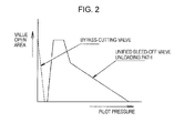
- Fig. 2 illustrates the opening characteristics of the unified bleed-off valves 27 and 28 and the bypass-cutting valves 35 and 36.
- the abscissa represents the pilot pressure generated by operating the remote-control valves, i.e., the spool stroke of the control valves 1 to 6.
- Second Embodiment (Fig. 3) is the pilot pressure generated by operating the remote-control valves, i.e., the spool stroke of the control valves 1 to 6.
- downstream pressures of the proportional solenoid valves 31 and 32 that control the unified bleed-off valves 27 and 28, respectively, are directly input to the bypass-cutting valves 35 and 36 as pilot pressures.
- a downstream pressure Pp of the switching-control valve 20 that controls the switching valve 18 is input to the bypass-cutting valves 35 and 36 as a pilot pressure.
- the controller 19 has a malfunction-detecting section 19a that detects abnormal conditions such as breaks in the wires in an output-signal system of the proportional solenoid valves 31 and 32 on the basis of reductions or the like in voltages or currents.
- the controller 19 stops outputting the signals to the switching-control valve 20, and the downstream pressure Pp of the switching-control valve 20 is reduced (becomes zero).
- the controller 19 stops outputting signals to the switching-control valve 20, and the downstream pressure Pp of the switching-control valve 20 is reduced as described above. With this, the bypass-cutting valves 35 and 36 operated by the downstream pressure Pp are switched to the corresponding unloading positions x, and the oil is unloaded through the central bypass lines 23 and 24.
- a common bypass-cutting valve 37 is disposed adjacent to the most downstream part of the central bypass lines 23 and 24.
- the bypass-cutting valve 37 opens or closes the central bypass lines 23 and 24 of the groups A and B, respectively, in a collective manner.
- the bypass-cutting valve 37 is controlled using the downstream pressure Pp of the switching-control valve 20 as in the second embodiment, and is switched from a blocking position y to an unloading position x so as to unload oil when the unified bleed-off valves 27 and 28 are switched to the fail-safe positions z due to an abnormality.
- the downstream pressures of the proportional solenoid valves 31 and 32 can be used as a pilot pressure for controlling the bypass-cutting valve 37 as in the first embodiment.
- bypass-cutting valves 38 and 39 are integrated into the control valves 3 and 6 disposed at the most downstream parts of the groups A and B, respectively, as sub-spools.
- the bypass-cutting valves 38 and 39 are switched according to the downstream pressures of the proportional solenoid valves 31 and 32 serving as the pilot pressures.
- the unified bleed-off valves 27 and 28 are configured to block the oil discharged from the pumps when the valves are in a neutral state.
- the unified bleed-off valves 27 and 28 can be configured to open the unloading paths thereof when the valves are in a neutral state, and the unloading paths can be connected to the central bypass lines 23 and 24.
- a hydraulic control device for a working machine includes control valves; hydraulic actuators controlled by corresponding control valves and divided into groups; unified bleed-off valves disposed on discharge lines of first and second hydraulic pumps; central bypass paths provided in the control valves, the central bypass paths of each group being connected in tandem so as to form a central bypass line; and bypass-cutting valves disposed on the central bypass lines, the bypass-cutting valves being automatically switched so as to open the central bypass lines when the unified bleed-off valves are not operated.
Landscapes
- Engineering & Computer Science (AREA)
- General Engineering & Computer Science (AREA)
- Mining & Mineral Resources (AREA)
- Civil Engineering (AREA)
- Structural Engineering (AREA)
- Physics & Mathematics (AREA)
- Fluid Mechanics (AREA)
- Mechanical Engineering (AREA)
- Fluid-Pressure Circuits (AREA)
- Operation Control Of Excavators (AREA)
Abstract
Description
- The present invention relates to hydraulic control devices for working machines such as hydraulic excavators.
- In hydraulic excavators, for example, some (surplus) oil discharged from pumps is returned (unloaded) to tanks (bleed-off control).
- In general, this control is performed by changing the opening areas of bleed-off paths formed in control valves for corresponding actuators in response to inputs through operating means.
- However, the length of the control valves is increased due to the length of the bleed-off paths in a spool shaft direction, resulting in an increase in cost and difficulty in assembling the control valves into machines.
- To date, in some technologies, a common unified bleed-off valve has been provided for a plurality of control valves (hydraulic actuators) instead of the above-described bleed-off paths for the corresponding control valves (unified bleed-off system).
- Moreover, a method for electronically controlling a hydraulic pilot valve serving as the unified bleed-off valve using a downstream pressure of a proportional solenoid valve that is controlled by a controller is often employed in such unified bleed-off systems (for example,
Japanese Unexamined Patent Application Publication No. 11-303809 - This unified bleed-off control method has high control flexibility compared with a hydraulic control method in which a pilot pressure according to the operation is directly input to the unified bleed-off valve.
- However, in this method, operation of the actuators may be hindered when the unified bleed-off valve fails.
- For example, if the unified bleed-off valve that blocks oil when it is in a neutral state fails while all the control valves are in a neutral state (all the actuators are not operated), a relief valve is operated and generates heat.
- In contrast, if the unified bleed-off valve that unloads oil when it is in a neutral state fails, the unloading state of the unified bleed-off valve is maintained. Thus, the actuators become inoperable, and the machine stops moving.
- In particular, in the above-described electronically controlled system, these problems are serious since the proportional solenoid valve often breaks down or the unified bleed-off valve often fails due to abnormalities such as breaks in wires that transmit control signals from the controller to the proportional solenoid valve in the control system.
- On the other hand, in hydraulic excavators, hydraulic actuators are divided into two groups, and the two groups are driven by separate pumps such that the total flow rate of the pumps is efficiently divided and distributed to the actuators in view of flow rates required for the hydraulic actuators, combined control, and the like.
- In this case, left and right driving motors (hydraulic motors) that drive crawler-mounted traveling sections belong to the separate groups, and are basically driven by the separate pumps.
- For example, in the case of the structure where oil discharged from two hydraulic pumps is distributed to two groups, it is preferable that the oil discharged from both pumps be merged and distributed to both groups for ensuring a required flow rate when control valves for both the driving motor and an attachment in the first group are operated at the same time (hereinafter referred to as a simultaneous operation).
- Therefore, a switching valve for switching flow channels is disposed at the discharge side of the pumps such that the oil discharged from both pumps is merged and distributed to both groups during the simultaneous operation.
- Accordingly, when the unified bleed-off control method is employed, the problems that occur during failure of the unified bleed-off valve must be solved with consideration of the above-described circuit structure.
- An object of the present invention is to provide a hydraulic control device for a working machine capable of ensuring the operation of hydraulic actuators and at the same time preventing heat caused by a relieving operation even when a unified bleed-off valve is not operated, the hydraulic actuators being divided into groups and driven by oil discharged from common pumps as required.
- First, the control device for controlling the oil pressure of the working machine includes the following basic structure.
- That is, the control device for controlling the oil pressure of the working machine includes control valves switched by operating means; hydraulic actuators separately controlled by corresponding control valves, the hydraulic actuators being divided into groups, oil discharged from common hydraulic pumps being supplied to the groups; unified bleed-off valves separately performing unified bleed-off operation on the groups on the basis of signals output from controlling means according to inputs from the operating means; central bypass paths provided in the control valves, the central bypass paths of each group being connected in tandem so as to form a central bypass line for unloading operation; and bypass-cutting valves disposed adjacent to the most downstream part of the central bypass lines for opening or closing the central bypass lines. The bypass-cutting valves are automatically switched on the basis of the signals output from controlling means, and open the central bypass lines when the unified bleed-off valves are not operated.
- With this structure, the oil discharged from the pumps is unloaded via the central bypass lines even when the unified bleed-off valves are not operated. Thus, even when the unified bleed-off valves are configured to block oil when it is in a neutral state, heat caused by a relieving operation can be prevented.
- Moreover, when the control valves are operated, the central bypass paths are closed such that the unloading operation via the central bypass lines is stopped, and the oil is supplied to the actuators. Thus, the operation of the actuators can be ensured.
- For example, it is assumed that hydraulic actuators are divided into first and second groups, and oil discharged from common pumps is distributed to both groups (a state where a switching valve for switching flow channels is switched to a simultaneous-operation position as described in a second aspect of the present invention). According to a known technology, the oil discharged from the pumps is unloaded via the central bypass line of the first group when all the control valves in the first group are in a neutral state. Therefore, the actuators in the second group cannot be operated.
- In contrast, according to the present invention including the bypass-cutting valves disposed adjacent to the most downstream part of the central bypass lines, the central bypass line in the first group is closed using the bypass-cutting valve, and thus the oil supply to the second group is ensured.
- That is, on the premise of a circuit structure in which the actuators are divided into multiple groups and the oil discharged from the common pumps is supplied to the groups, the unified bleed-off control method using unified bleed-off valves can be employed while heat caused by a relieving operation during failure of the unified bleed-off valves can be prevented and the operation of the actuators can be ensured both during failure and during normal operation of the unified bleed-off valves.
- Moreover, since the bypass-cutting valves are automatically switched on the basis of the signals output from the controlling means, the central bypass lines are appropriately and reliably opened or closed without switching errors.
- It is preferable that the control device further includes a switching valve for switching flow channels, the switching valve controlling the oil supply to the groups. Moreover, it is preferable that the hydraulic actuators for motors that drive left and right crawlers belong to separate groups, and the switching valve be switched to a simultaneous-operation position where oil discharged from the common hydraulic pumps is supplied to the groups when the control valve for one of the driving motors and the control valve for one of the other hydraulic actuators included in the same group are operated at the same time.
- It is preferable that the bypass-cutting valves be integrated into a common valve that opens or closes the central bypass lines of corresponding groups at the same time.
- With this structure, one bypass-cutting valve can suffice for the plurality of groups. This leads to a simplified circuit structure, and is advantageous costwise.
- It is preferable that the bypass-cutting valves be switched on the basis of signals common with those input to the unified bleed-off valves, and are opened when the unified bleed-off valves are not operated.
- With this structure, the bypass-cutting valves are drivingly connected to the unified bleed-off valve. Therefore, the oil discharged from the pumps can be reliably unloaded when the unified bleed-off valves are not operated.
- It is preferable that the bypass-cutting valves are integrated into the control valves disposed at the most downstream parts of the corresponding groups as sub-spools.
- This leads to space-saving and a simplified pipeline structure.
-
- Fig. 1 illustrates the circuit structure according to a first embodiment of the present invention;
- Fig. 2 illustrates opening characteristics of a unified bleed-off valve and a bypass-cutting valve according to the first embodiment;
- Fig. 3 illustrates the circuit structure according to a second embodiment of the present invention;
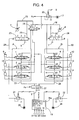
- Fig. 4 illustrates the circuit structure according to a third embodiment of the present invention; and
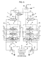
- Fig. 5 illustrates the circuit structure according to a fourth embodiment of the present invention.
- Embodiments of the present invention will now be described with reference to Figs. 1 to 5.
- In the following embodiments, the present invention is applied to a hydraulic excavator.
- In this embodiment, hydraulic actuators are grouped into a first group A including a right driving motor, a bucket cylinder, and boom cylinder (not shown), and
control valves control valves hydraulic pump 7, and the actuators in the second group B are driven by a secondhydraulic pump 8. Remote-control valves 9 to 14 are operating means for operating thecontrol valves 1 to 6, respectively. - A
switching valve 18 that switches flow channels is disposed ondischarge lines hydraulic pumps switching valve 18 is of the hydraulic pilot type, and is driven by a pilot-pressure source 17. This ensures the flow rate required for driving the hydraulic actuators when the two (or three) control valves for the hydraulic actuator for the traveling section and the other hydraulic actuator(s) included in the same group are operated at the same time (simultaneous operation). - The
switching valve 18 is switched between a normal position x and a simultaneous-operation position y. At the normal position x, oil discharged from the firsthydraulic pump 7 is supplied to the first group A including the right driving motor, and oil discharged from the secondhydraulic pump 8 is supplied to the second group B including the left driving motor. - In contrast, during the above-described simultaneous operation, the
switching valve 18 is switched from the normal position x to the simultaneous-operation position y by a pilot pressure supplied from a switching-control valve 20 of the proportional solenoid type to theswitching valve 18 on the basis of signals S output from acontroller 19 according to operating signals. - In this state, the oil discharged from both the
hydraulic pumps - In the group A, the
control valves 1 to 3 each have acentral bypass path 21. In the group B, thecontrol valves 4 to 6 each have acentral bypass path 22. Thecentral bypass paths 21 are connected in tandem so as to form acentral bypass line 23. At this time, thecontrol valve 1 for the driving motor is disposed at the most upstream part of thecentral bypass line 23. Similarly, thecentral bypass paths 22 are connected in tandem so as to form acentral bypass line 24. At this time, thecontrol valve 4 for the other driving motor is disposed at the most upstream part of thecentral bypass line 24. - In the first group A, the upstream portion of the
central bypass line 23 is connected to thedischarge line 15 of the firsthydraulic pump 7 via the switchingvalve 18. In the second group B, the upstream portion of thecentral bypass line 24 is directly connected to thedischarge line 16 of the secondhydraulic pump 8. The downstream portions of thecentral bypass lines - On the other hand, unified bleed-off
pipelines hydraulic pumps valves pipelines - The unified bleed-off
valves - Moreover, the unified bleed-off
valves -
Proportional solenoid valves controller 19 are disposed onpilot lines valves proportional solenoid valves valves Reference numbers proportional solenoid valves - Bypass-cutting
valves central bypass lines proportional solenoid valves valves - The bypass-cutting
valves proportional solenoid valves - When no downstream pressures are output from the
proportional solenoid valves valves valves central bypass lines - In a normal state, when the remote-
control valves 9 to 14 are operated, the corresponding control valves are actuated, and the corresponding hydraulic actuators are operated. At the same time, signals are output from thecontroller 19 to theproportional solenoid valves valves proportional solenoid valves - Moreover, the downstream pressures of the
proportional solenoid valves valves valves - When the switching
valve 18 is switched to the simultaneous-operation position y, oil discharged from thehydraulic pumps - At this time, the bypass-cutting
valves central bypass lines central bypass line 23 of the first group A, and the actuators in the second group B can be operated. - On the other hand, when an unusual event such as a break in the wires of a control system connecting the
controller 19 and theproportional solenoid valves proportional solenoid valves valves - In this state, the unloading paths of the unified bleed-off
valves - In this case, the bleed-off operation in the groups A and B is performed through the
central bypass paths control valves 1 to 3 and thecontrol valves 4 to 6, respectively. - That is, since the unified bleed-off
valves control valves 1 to 6. - If the
control valves 1 to 6 are configured to ensure necessary and sufficient bleed-off function, the length of thecontrol valves 1 to 6 in a spool shaft direction needs to be increased. This goes against the original object of reducing the size of the control valves by means of the unified bleed-offvalves - Therefore, the opening characteristics of the
control valves 1 to 6 and the unified bleed-offvalves central bypass paths control valves 1 to 6 is started, and that the bleed-off operation of the unified bleed-offvalves central bypass paths - Moreover, the opening characteristics of the bypass-cutting
valves control valves 1 to 6 in accordance with the closing of thecentral bypass paths - Fig. 2 illustrates the opening characteristics of the unified bleed-off
valves valves control valves 1 to 6. Second Embodiment (Fig. 3) - In the following embodiment, only differences from the first embodiment will be described.
- In the first embodiment, the downstream pressures of the
proportional solenoid valves valves valves control valve 20 that controls the switchingvalve 18 is input to the bypass-cuttingvalves - In this case, the
controller 19 has a malfunction-detectingsection 19a that detects abnormal conditions such as breaks in the wires in an output-signal system of theproportional solenoid valves controller 19 stops outputting the signals to the switching-control valve 20, and the downstream pressure Pp of the switching-control valve 20 is reduced (becomes zero). - With this structure, when the switching
valve 18 is switched to the simultaneous-operation position y, the bypass-cuttingvalves central bypass lines hydraulic pumps - On the other hand, when the unified bleed-off
valves controller 19 stops outputting signals to the switching-control valve 20, and the downstream pressure Pp of the switching-control valve 20 is reduced as described above. With this, the bypass-cuttingvalves central bypass lines - In a third embodiment, a common bypass-cutting
valve 37 is disposed adjacent to the most downstream part of thecentral bypass lines valve 37 opens or closes thecentral bypass lines - The bypass-cutting
valve 37 is controlled using the downstream pressure Pp of the switching-control valve 20 as in the second embodiment, and is switched from a blocking position y to an unloading position x so as to unload oil when the unified bleed-offvalves - With this structure, the two groups A and B share one bypass-cutting valve. This leads to a simplified circuit structure, and is advantageous costwise.
- The downstream pressures of the
proportional solenoid valves valve 37 as in the first embodiment. - In a fourth embodiment, bypass-cutting
valves control valves valves proportional solenoid valves - With this structure, no independent bypass-cutting valves are required. This leads to space-saving and a simplified pipeline structure.
- In the above-described embodiments, the unified bleed-off
valves valves central bypass lines - Although the invention has been described with reference to the preferred embodiments in the attached figures, it is noted that equivalents may be employed and substitutions made herein without departing from the scope of the invention as recited in the claims.
- A hydraulic control device for a working machine includes control valves; hydraulic actuators controlled by corresponding control valves and divided into groups; unified bleed-off valves disposed on discharge lines of first and second hydraulic pumps; central bypass paths provided in the control valves, the central bypass paths of each group being connected in tandem so as to form a central bypass line; and bypass-cutting valves disposed on the central bypass lines, the bypass-cutting valves being automatically switched so as to open the central bypass lines when the unified bleed-off valves are not operated.
Claims (5)
- A hydraulic control device for a working machine comprising:control valves switched by operating means;hydraulic actuators separately controlled by corresponding control valves, the hydraulic actuators being divided into groups, oil discharged from common hydraulic pumps being supplied to the groups;unified bleed-off valves separately performing unified bleed-off operation on the groups on the basis of signals output from controlling means according to inputs from the operating means;central bypass paths provided in the control valves, the central bypass paths of each group being connected in tandem so as to form a central bypass line for unloading operation; andbypass-cutting valves disposed adjacent to the most downstream part of the central bypass lines for opening or closing the central bypass lines, whereinthe bypass-cutting valves are automatically switched on the basis of the signals output from the controlling means, and are adapted to open the central bypass lines when the unified bleed-off valves are not operated.
- The hydraulic control device according to Claim 1, further comprising:a switching valve for switching flow channels, the switching valve controlling the oil supply to the groups, whereinthe hydraulic actuators for motors that drive left and right crawlers belong to separate groups; andthe switching valve is switched to a simultaneous-operation position where oil discharged from the common hydraulic pumps is supplied to the groups when the control valve for one of the driving motors and the control valve for one of the other hydraulic actuators included in the same group are operated at the same time.
- The hydraulic control device according to Claim 1, wherein the bypass-cutting valves are integrated into a common valve that opens or closes the central bypass lines of corresponding groups at the same time.
- The hydraulic control device according to Claim 3, wherein the bypass-cutting valves are switched on the basis of signals common with those input to the unified bleed-off valves, and are opened when the unified bleed-off valves are not operated.
- The hydraulic control device according to Claim 1, wherein the bypass-cutting valves are integrated into the control valves disposed at the most downstream parts of the corresponding groups as sub-spools.
Applications Claiming Priority (1)
| Application Number | Priority Date | Filing Date | Title |
|---|---|---|---|
| JP2006012206A JP4232784B2 (en) | 2006-01-20 | 2006-01-20 | Hydraulic control device for work machine |
Publications (3)
| Publication Number | Publication Date |
|---|---|
| EP1811185A2 true EP1811185A2 (en) | 2007-07-25 |
| EP1811185A3 EP1811185A3 (en) | 2009-11-04 |
| EP1811185B1 EP1811185B1 (en) | 2013-04-10 |
Family
ID=37768768
Family Applications (1)
| Application Number | Title | Priority Date | Filing Date |
|---|---|---|---|
| EP06127235.7A Not-in-force EP1811185B1 (en) | 2006-01-20 | 2006-12-27 | Hydraulic control device for working machine |
Country Status (4)
| Country | Link |
|---|---|
| US (1) | US7594395B2 (en) |
| EP (1) | EP1811185B1 (en) |
| JP (1) | JP4232784B2 (en) |
| CN (1) | CN101003977B (en) |
Cited By (2)
| Publication number | Priority date | Publication date | Assignee | Title |
|---|---|---|---|---|
| EP2863066A4 (en) * | 2012-06-15 | 2015-12-02 | Sumitomo Shi Constr Mach Co | HYDRAULIC CIRCUIT OF CONSTRUCTION MACHINE |
| EP3492661A4 (en) * | 2016-07-29 | 2019-08-07 | Sumitomo (S.H.I.) Construction Machinery Co., Ltd. | EXCAVATOR AND CONTROL VALVE FOR EXCAVATOR |
Families Citing this family (21)
| Publication number | Priority date | Publication date | Assignee | Title |
|---|---|---|---|---|
| JP4819510B2 (en) * | 2006-01-20 | 2011-11-24 | コベルコ建機株式会社 | Hydraulic control device for work machine |
| JP4232784B2 (en) | 2006-01-20 | 2009-03-04 | コベルコ建機株式会社 | Hydraulic control device for work machine |
| JP5216265B2 (en) | 2006-10-10 | 2013-06-19 | Necトーキン株式会社 | Inductance element, filter circuit, and noise filter |
| WO2013082331A1 (en) * | 2011-11-29 | 2013-06-06 | Vanguard Equipment, Inc. | Auxiliary flow valve system and method for managing load flow requirements for auxiliary functions on a tractor hydraulic system |
| CN102677733B (en) * | 2012-05-23 | 2014-12-03 | 徐州徐工挖掘机械有限公司 | Device and method for improving traveling and operating intuitiveness of excavator |
| JP5778086B2 (en) * | 2012-06-15 | 2015-09-16 | 住友建機株式会社 | Hydraulic circuit of construction machine and its control device |
| JP5985276B2 (en) * | 2012-07-02 | 2016-09-06 | 住友建機株式会社 | Hydraulic circuit of construction machine and its control device |
| JP6013888B2 (en) * | 2012-11-20 | 2016-10-25 | 株式会社Kcm | Hydraulic drive system and construction machine including the same |
| CA2893575C (en) * | 2012-12-14 | 2018-07-10 | Volvo Construction Equipment Ab | Hydraulic circuit for construction machines |
| CN103352886B (en) * | 2013-06-28 | 2015-12-23 | 山河智能装备股份有限公司 | Hydraulic control valve for energy recovery |
| EP3026181B1 (en) * | 2013-07-24 | 2018-11-14 | Volvo Construction Equipment AB | Hydraulic circuit for construction machine |
| KR102128630B1 (en) * | 2014-03-24 | 2020-06-30 | 두산인프라코어 주식회사 | control method for Swing motor of Hydraulic system |
| JP6013389B2 (en) | 2014-03-24 | 2016-10-25 | 日立建機株式会社 | Hydraulic system of work machine |
| JP6463649B2 (en) * | 2015-03-13 | 2019-02-06 | 川崎重工業株式会社 | Hydraulic drive system for construction machinery |
| EP3290595B1 (en) * | 2015-04-29 | 2021-02-17 | Volvo Construction Equipment AB | Flow rate control apparatus of construction equipment and control method therefor |
| JP6654521B2 (en) * | 2016-07-15 | 2020-02-26 | 日立建機株式会社 | Construction machinery |
| CN107725507A (en) * | 2017-11-22 | 2018-02-23 | 江苏恒立液压科技有限公司 | The control method of hydraulic control system |
| JP6924161B2 (en) | 2018-02-28 | 2021-08-25 | 川崎重工業株式会社 | Hydraulic system for construction machinery |
| JP7221101B2 (en) * | 2019-03-20 | 2023-02-13 | 日立建機株式会社 | excavator |
| US11965315B2 (en) * | 2021-03-09 | 2024-04-23 | Hitachi Construction Machinery Co., Ltd. | Work machine |
| US12313093B2 (en) * | 2021-08-10 | 2025-05-27 | Hd Hyundai Infracore Co., Ltd. | Hydraulic system |
Citations (1)
| Publication number | Priority date | Publication date | Assignee | Title |
|---|---|---|---|---|
| US20030037465A1 (en) | 2001-08-22 | 2003-02-27 | Kobelco Construction Machinery Co. Ltd., | Hydraulic system for construction machine |
Family Cites Families (15)
| Publication number | Priority date | Publication date | Assignee | Title |
|---|---|---|---|---|
| US4030623A (en) * | 1971-12-13 | 1977-06-21 | Caterpillar Tractor Co. | Hydraulic circuitry for an excavator |
| JP2654484B2 (en) * | 1988-08-04 | 1997-09-17 | 油谷重工株式会社 | Hydraulic circuit of construction machinery |
| JPH07116721B2 (en) * | 1989-01-31 | 1995-12-13 | 油谷重工株式会社 | Hydraulic circuit of hydraulic excavator |
| JPH11303809A (en) | 1998-04-20 | 1999-11-02 | Komatsu Ltd | Pump control device for hydraulic drive machine |
| JP4111286B2 (en) * | 1998-06-30 | 2008-07-02 | コベルコ建機株式会社 | Construction machine traveling control method and apparatus |
| JP2000170212A (en) | 1998-07-07 | 2000-06-20 | Yutani Heavy Ind Ltd | Hydraulic control equipment for work machines |
| JP3943779B2 (en) * | 1999-01-19 | 2007-07-11 | 日立建機株式会社 | Hydraulic drive system for civil engineering and construction machinery |
| JP3621601B2 (en) * | 1999-03-31 | 2005-02-16 | コベルコ建機株式会社 | Hydraulic circuit for construction machinery |
| JP3491600B2 (en) * | 2000-04-13 | 2004-01-26 | コベルコ建機株式会社 | Hydraulic control circuit for construction machinery |
| JP3649139B2 (en) * | 2001-03-15 | 2005-05-18 | コベルコ建機株式会社 | Travel control device |
| JP2003090302A (en) | 2001-07-09 | 2003-03-28 | Kobelco Contstruction Machinery Ltd | Hydraulic control circuit of construction machine |
| US7155909B2 (en) * | 2003-05-15 | 2007-01-02 | Kobelco Construction Machinery Co., Ltd. | Hydraulic controller for working machine |
| JP4096901B2 (en) * | 2004-03-17 | 2008-06-04 | コベルコ建機株式会社 | Hydraulic control device for work machine |
| US7178333B2 (en) * | 2004-03-18 | 2007-02-20 | Kobelco Construction Machinery Co., Ltd. | Hydraulic control system for hydraulic excavator |
| JP4232784B2 (en) | 2006-01-20 | 2009-03-04 | コベルコ建機株式会社 | Hydraulic control device for work machine |
-
2006
- 2006-01-20 JP JP2006012206A patent/JP4232784B2/en not_active Expired - Lifetime
- 2006-12-19 US US11/612,909 patent/US7594395B2/en active Active
- 2006-12-27 EP EP06127235.7A patent/EP1811185B1/en not_active Not-in-force
-
2007
- 2007-01-22 CN CN200710004431.5A patent/CN101003977B/en not_active Expired - Fee Related
Patent Citations (1)
| Publication number | Priority date | Publication date | Assignee | Title |
|---|---|---|---|---|
| US20030037465A1 (en) | 2001-08-22 | 2003-02-27 | Kobelco Construction Machinery Co. Ltd., | Hydraulic system for construction machine |
Cited By (4)
| Publication number | Priority date | Publication date | Assignee | Title |
|---|---|---|---|---|
| EP2863066A4 (en) * | 2012-06-15 | 2015-12-02 | Sumitomo Shi Constr Mach Co | HYDRAULIC CIRCUIT OF CONSTRUCTION MACHINE |
| EP3203086A1 (en) * | 2012-06-15 | 2017-08-09 | Sumitomo (S.H.I.) Construction Machinery Co., Ltd. | Hydraulic circuit for construction machine |
| EP3492661A4 (en) * | 2016-07-29 | 2019-08-07 | Sumitomo (S.H.I.) Construction Machinery Co., Ltd. | EXCAVATOR AND CONTROL VALVE FOR EXCAVATOR |
| US11078646B2 (en) | 2016-07-29 | 2021-08-03 | Sumitomo(S.H.I.) Construction Machinery Co., Ltd. | Shovel and control valve for shovel |
Also Published As
| Publication number | Publication date |
|---|---|
| EP1811185A3 (en) | 2009-11-04 |
| CN101003977A (en) | 2007-07-25 |
| US7594395B2 (en) | 2009-09-29 |
| CN101003977B (en) | 2013-01-16 |
| US20070169474A1 (en) | 2007-07-26 |
| JP4232784B2 (en) | 2009-03-04 |
| JP2007192344A (en) | 2007-08-02 |
| EP1811185B1 (en) | 2013-04-10 |
Similar Documents
| Publication | Publication Date | Title |
|---|---|---|
| US7594395B2 (en) | Hydraulic control device for working machine | |
| CN100385081C (en) | Hydraulic controls for work machines | |
| JP3689211B2 (en) | Flow confluence device for heavy equipment | |
| EP1820909B1 (en) | Hydraulic controlling device for a working machine | |
| EP2107170B1 (en) | Hydraulic drive system for a civil engineering or construction machine. | |
| CN104220763B (en) | Hydraulic circuit and control device of construction machinery | |
| CN107587548B (en) | Hydraulic circuit of construction machine | |
| EP1975324B1 (en) | Hydraulic circuit for construction equipment | |
| JP2005265016A (en) | Hydraulic control device for working machine | |
| EP3249117B1 (en) | Control system for construction machine | |
| US20100011757A1 (en) | Safety Device for Hydraulic Working Machine | |
| JP6463649B2 (en) | Hydraulic drive system for construction machinery | |
| US5568727A (en) | Straight travelling apparatus for heavy construction equipment | |
| US5680759A (en) | Straight travelling apparatus for heavy construction equipment | |
| KR100527378B1 (en) | hydraulic circuit of option device of heavy equipment of having spool boom joint | |
| WO2020031816A1 (en) | Construction-machinery hydraulic circuit | |
| JP2004360898A (en) | Hydraulic control device for working machine | |
| JP4819510B2 (en) | Hydraulic control device for work machine | |
| CN110226010B (en) | Hydraulic control system for construction machine | |
| EP4707475A2 (en) | Hydraulic circuit for construction machine | |
| JP2000192907A (en) | Operation device of pilot operation directional control valve | |
| JPH0112965B2 (en) |
Legal Events
| Date | Code | Title | Description |
|---|---|---|---|
| PUAI | Public reference made under article 153(3) epc to a published international application that has entered the european phase |
Free format text: ORIGINAL CODE: 0009012 |
|
| 17P | Request for examination filed |
Effective date: 20061227 |
|
| AK | Designated contracting states |
Kind code of ref document: A2 Designated state(s): AT BE BG CH CY CZ DE DK EE ES FI FR GB GR HU IE IS IT LI LT LU LV MC NL PL PT RO SE SI SK TR |
|
| AX | Request for extension of the european patent |
Extension state: AL BA HR MK YU |
|
| PUAL | Search report despatched |
Free format text: ORIGINAL CODE: 0009013 |
|
| AK | Designated contracting states |
Kind code of ref document: A3 Designated state(s): AT BE BG CH CY CZ DE DK EE ES FI FR GB GR HU IE IS IT LI LT LU LV MC NL PL PT RO SE SI SK TR |
|
| AX | Request for extension of the european patent |
Extension state: AL BA HR MK RS |
|
| 17Q | First examination report despatched |
Effective date: 20100608 |
|
| AKX | Designation fees paid |
Designated state(s): AT BE BG CH CY CZ DE DK EE ES FI FR GB GR HU IE IS IT LI LT LU LV MC NL PL PT RO SE SI SK TR |
|
| GRAP | Despatch of communication of intention to grant a patent |
Free format text: ORIGINAL CODE: EPIDOSNIGR1 |
|
| GRAS | Grant fee paid |
Free format text: ORIGINAL CODE: EPIDOSNIGR3 |
|
| GRAA | (expected) grant |
Free format text: ORIGINAL CODE: 0009210 |
|
| AK | Designated contracting states |
Kind code of ref document: B1 Designated state(s): AT BE BG CH CY CZ DE DK EE ES FI FR GB GR HU IE IS IT LI LT LU LV MC NL PL PT RO SE SI SK TR |
|
| REG | Reference to a national code |
Ref country code: GB Ref legal event code: FG4D |
|
| REG | Reference to a national code |
Ref country code: CH Ref legal event code: EP Ref country code: AT Ref legal event code: REF Ref document number: 606167 Country of ref document: AT Kind code of ref document: T Effective date: 20130415 |
|
| REG | Reference to a national code |
Ref country code: IE Ref legal event code: FG4D |
|
| REG | Reference to a national code |
Ref country code: DE Ref legal event code: R096 Ref document number: 602006035532 Country of ref document: DE Effective date: 20130606 |
|
| PG25 | Lapsed in a contracting state [announced via postgrant information from national office to epo] |
Ref country code: SI Free format text: LAPSE BECAUSE OF FAILURE TO SUBMIT A TRANSLATION OF THE DESCRIPTION OR TO PAY THE FEE WITHIN THE PRESCRIBED TIME-LIMIT Effective date: 20130410 |
|
| REG | Reference to a national code |
Ref country code: AT Ref legal event code: MK05 Ref document number: 606167 Country of ref document: AT Kind code of ref document: T Effective date: 20130410 |
|
| REG | Reference to a national code |
Ref country code: NL Ref legal event code: VDEP Effective date: 20130410 Ref country code: LT Ref legal event code: MG4D |
|
| PG25 | Lapsed in a contracting state [announced via postgrant information from national office to epo] |
Ref country code: FI Free format text: LAPSE BECAUSE OF FAILURE TO SUBMIT A TRANSLATION OF THE DESCRIPTION OR TO PAY THE FEE WITHIN THE PRESCRIBED TIME-LIMIT Effective date: 20130410 Ref country code: GR Free format text: LAPSE BECAUSE OF FAILURE TO SUBMIT A TRANSLATION OF THE DESCRIPTION OR TO PAY THE FEE WITHIN THE PRESCRIBED TIME-LIMIT Effective date: 20130711 Ref country code: SE Free format text: LAPSE BECAUSE OF FAILURE TO SUBMIT A TRANSLATION OF THE DESCRIPTION OR TO PAY THE FEE WITHIN THE PRESCRIBED TIME-LIMIT Effective date: 20130410 Ref country code: LT Free format text: LAPSE BECAUSE OF FAILURE TO SUBMIT A TRANSLATION OF THE DESCRIPTION OR TO PAY THE FEE WITHIN THE PRESCRIBED TIME-LIMIT Effective date: 20130410 Ref country code: AT Free format text: LAPSE BECAUSE OF FAILURE TO SUBMIT A TRANSLATION OF THE DESCRIPTION OR TO PAY THE FEE WITHIN THE PRESCRIBED TIME-LIMIT Effective date: 20130410 Ref country code: ES Free format text: LAPSE BECAUSE OF FAILURE TO SUBMIT A TRANSLATION OF THE DESCRIPTION OR TO PAY THE FEE WITHIN THE PRESCRIBED TIME-LIMIT Effective date: 20130721 Ref country code: IS Free format text: LAPSE BECAUSE OF FAILURE TO SUBMIT A TRANSLATION OF THE DESCRIPTION OR TO PAY THE FEE WITHIN THE PRESCRIBED TIME-LIMIT Effective date: 20130810 Ref country code: BE Free format text: LAPSE BECAUSE OF FAILURE TO SUBMIT A TRANSLATION OF THE DESCRIPTION OR TO PAY THE FEE WITHIN THE PRESCRIBED TIME-LIMIT Effective date: 20130410 Ref country code: NL Free format text: LAPSE BECAUSE OF FAILURE TO SUBMIT A TRANSLATION OF THE DESCRIPTION OR TO PAY THE FEE WITHIN THE PRESCRIBED TIME-LIMIT Effective date: 20130410 |
|
| PG25 | Lapsed in a contracting state [announced via postgrant information from national office to epo] |
Ref country code: BG Free format text: LAPSE BECAUSE OF FAILURE TO SUBMIT A TRANSLATION OF THE DESCRIPTION OR TO PAY THE FEE WITHIN THE PRESCRIBED TIME-LIMIT Effective date: 20130710 Ref country code: LV Free format text: LAPSE BECAUSE OF FAILURE TO SUBMIT A TRANSLATION OF THE DESCRIPTION OR TO PAY THE FEE WITHIN THE PRESCRIBED TIME-LIMIT Effective date: 20130410 Ref country code: PL Free format text: LAPSE BECAUSE OF FAILURE TO SUBMIT A TRANSLATION OF THE DESCRIPTION OR TO PAY THE FEE WITHIN THE PRESCRIBED TIME-LIMIT Effective date: 20130410 Ref country code: CY Free format text: LAPSE BECAUSE OF FAILURE TO SUBMIT A TRANSLATION OF THE DESCRIPTION OR TO PAY THE FEE WITHIN THE PRESCRIBED TIME-LIMIT Effective date: 20130410 |
|
| PG25 | Lapsed in a contracting state [announced via postgrant information from national office to epo] |
Ref country code: SK Free format text: LAPSE BECAUSE OF FAILURE TO SUBMIT A TRANSLATION OF THE DESCRIPTION OR TO PAY THE FEE WITHIN THE PRESCRIBED TIME-LIMIT Effective date: 20130410 Ref country code: CZ Free format text: LAPSE BECAUSE OF FAILURE TO SUBMIT A TRANSLATION OF THE DESCRIPTION OR TO PAY THE FEE WITHIN THE PRESCRIBED TIME-LIMIT Effective date: 20130410 Ref country code: DK Free format text: LAPSE BECAUSE OF FAILURE TO SUBMIT A TRANSLATION OF THE DESCRIPTION OR TO PAY THE FEE WITHIN THE PRESCRIBED TIME-LIMIT Effective date: 20130410 Ref country code: EE Free format text: LAPSE BECAUSE OF FAILURE TO SUBMIT A TRANSLATION OF THE DESCRIPTION OR TO PAY THE FEE WITHIN THE PRESCRIBED TIME-LIMIT Effective date: 20130410 |
|
| PLBE | No opposition filed within time limit |
Free format text: ORIGINAL CODE: 0009261 |
|
| STAA | Information on the status of an ep patent application or granted ep patent |
Free format text: STATUS: NO OPPOSITION FILED WITHIN TIME LIMIT |
|
| PG25 | Lapsed in a contracting state [announced via postgrant information from national office to epo] |
Ref country code: RO Free format text: LAPSE BECAUSE OF FAILURE TO SUBMIT A TRANSLATION OF THE DESCRIPTION OR TO PAY THE FEE WITHIN THE PRESCRIBED TIME-LIMIT Effective date: 20130410 |
|
| 26N | No opposition filed |
Effective date: 20140113 |
|
| REG | Reference to a national code |
Ref country code: DE Ref legal event code: R097 Ref document number: 602006035532 Country of ref document: DE Effective date: 20140113 |
|
| REG | Reference to a national code |
Ref country code: CH Ref legal event code: PL |
|
| PG25 | Lapsed in a contracting state [announced via postgrant information from national office to epo] |
Ref country code: LU Free format text: LAPSE BECAUSE OF FAILURE TO SUBMIT A TRANSLATION OF THE DESCRIPTION OR TO PAY THE FEE WITHIN THE PRESCRIBED TIME-LIMIT Effective date: 20131227 Ref country code: MC Free format text: LAPSE BECAUSE OF FAILURE TO SUBMIT A TRANSLATION OF THE DESCRIPTION OR TO PAY THE FEE WITHIN THE PRESCRIBED TIME-LIMIT Effective date: 20130410 |
|
| REG | Reference to a national code |
Ref country code: IE Ref legal event code: MM4A |
|
| PG25 | Lapsed in a contracting state [announced via postgrant information from national office to epo] |
Ref country code: LI Free format text: LAPSE BECAUSE OF NON-PAYMENT OF DUE FEES Effective date: 20131231 Ref country code: CH Free format text: LAPSE BECAUSE OF NON-PAYMENT OF DUE FEES Effective date: 20131231 Ref country code: IE Free format text: LAPSE BECAUSE OF NON-PAYMENT OF DUE FEES Effective date: 20131227 |
|
| PG25 | Lapsed in a contracting state [announced via postgrant information from national office to epo] |
Ref country code: TR Free format text: LAPSE BECAUSE OF FAILURE TO SUBMIT A TRANSLATION OF THE DESCRIPTION OR TO PAY THE FEE WITHIN THE PRESCRIBED TIME-LIMIT Effective date: 20130410 |
|
| PG25 | Lapsed in a contracting state [announced via postgrant information from national office to epo] |
Ref country code: HU Free format text: LAPSE BECAUSE OF FAILURE TO SUBMIT A TRANSLATION OF THE DESCRIPTION OR TO PAY THE FEE WITHIN THE PRESCRIBED TIME-LIMIT; INVALID AB INITIO Effective date: 20061227 |
|
| REG | Reference to a national code |
Ref country code: FR Ref legal event code: PLFP Year of fee payment: 10 |
|
| PG25 | Lapsed in a contracting state [announced via postgrant information from national office to epo] |
Ref country code: PT Free format text: LAPSE BECAUSE OF FAILURE TO SUBMIT A TRANSLATION OF THE DESCRIPTION OR TO PAY THE FEE WITHIN THE PRESCRIBED TIME-LIMIT Effective date: 20130410 |
|
| REG | Reference to a national code |
Ref country code: FR Ref legal event code: PLFP Year of fee payment: 11 |
|
| REG | Reference to a national code |
Ref country code: FR Ref legal event code: PLFP Year of fee payment: 12 |
|
| PGFP | Annual fee paid to national office [announced via postgrant information from national office to epo] |
Ref country code: GB Payment date: 20201216 Year of fee payment: 15 Ref country code: FR Payment date: 20201112 Year of fee payment: 15 Ref country code: IT Payment date: 20201110 Year of fee payment: 15 Ref country code: DE Payment date: 20201216 Year of fee payment: 15 |
|
| REG | Reference to a national code |
Ref country code: DE Ref legal event code: R119 Ref document number: 602006035532 Country of ref document: DE |
|
| GBPC | Gb: european patent ceased through non-payment of renewal fee |
Effective date: 20211227 |
|
| PG25 | Lapsed in a contracting state [announced via postgrant information from national office to epo] |
Ref country code: GB Free format text: LAPSE BECAUSE OF NON-PAYMENT OF DUE FEES Effective date: 20211227 Ref country code: DE Free format text: LAPSE BECAUSE OF NON-PAYMENT OF DUE FEES Effective date: 20220701 |
|
| PG25 | Lapsed in a contracting state [announced via postgrant information from national office to epo] |
Ref country code: FR Free format text: LAPSE BECAUSE OF NON-PAYMENT OF DUE FEES Effective date: 20211231 |
|
| PG25 | Lapsed in a contracting state [announced via postgrant information from national office to epo] |
Ref country code: IT Free format text: LAPSE BECAUSE OF NON-PAYMENT OF DUE FEES Effective date: 20211227 |