EP1810924A1 - Integrated package pacer for strapping machine - Google Patents
Integrated package pacer for strapping machine Download PDFInfo
- Publication number
- EP1810924A1 EP1810924A1 EP07100128A EP07100128A EP1810924A1 EP 1810924 A1 EP1810924 A1 EP 1810924A1 EP 07100128 A EP07100128 A EP 07100128A EP 07100128 A EP07100128 A EP 07100128A EP 1810924 A1 EP1810924 A1 EP 1810924A1
- Authority
- EP
- European Patent Office
- Prior art keywords
- package
- pacer
- pacing
- feed
- feed conveyor
- Prior art date
- Legal status (The legal status is an assumption and is not a legal conclusion. Google has not performed a legal analysis and makes no representation as to the accuracy of the status listed.)
- Granted
Links
- 102100026827 Protein associated with UVRAG as autophagy enhancer Human genes 0.000 title claims abstract description 57
- 101710102978 Protein associated with UVRAG as autophagy enhancer Proteins 0.000 title claims abstract description 57
- 238000004806 packaging method and process Methods 0.000 claims abstract description 5
- 238000011144 upstream manufacturing Methods 0.000 description 3
- 238000004519 manufacturing process Methods 0.000 description 2
- 230000003466 anti-cipated effect Effects 0.000 description 1
Images


Classifications
-
- B—PERFORMING OPERATIONS; TRANSPORTING
- B65—CONVEYING; PACKING; STORING; HANDLING THIN OR FILAMENTARY MATERIAL
- B65B—MACHINES, APPARATUS OR DEVICES FOR, OR METHODS OF, PACKAGING ARTICLES OR MATERIALS; UNPACKING
- B65B13/00—Bundling articles
- B65B13/02—Applying and securing binding material around articles or groups of articles, e.g. using strings, wires, strips, bands or tapes
- B65B13/04—Applying and securing binding material around articles or groups of articles, e.g. using strings, wires, strips, bands or tapes with means for guiding the binding material around the articles prior to severing from supply
- B65B13/06—Stationary ducts or channels
Definitions
- the present invention is directed to an improved feed system for a strapping machine. More particularly, the present invention is directed to a pacer that prevents overfeeding packages into a strapping machine.
- Strapping machines are in widespread use for securing straps around loads. Strappers are often used in production lines that operate at relatively high speeds. These lines are for the most part automated, however, operators are generally required at certain points along the line, including at the infeed to the strapper.
- a pacer that limits the rate at which packages are fed into the strapper.
- such a pacer provides a physical stop of the packages to prevent overloading the packages in the strapper.
- such a pacer is automated so that the sensing of the presence or absence of a package functions to permit or prevent movement of packages into the strapper.
- a package pacer is configured for use with an automatic strapping machine.
- the pacer provides a physical stop of packages to prevent overloading the packages in the strapper.
- Such a pacer is automated so that the sensing of the presence or absence of a package functions to permit or prevent movement of packages into the strapper.
- the strapping machine with which the pacer is used has a strap chute through which strap material is fed and from which strap material is tensioned onto the package.
- the strapping machine has an in-feed conveyor that defines a plane and is configured to automatically move the package into a packaging region bounded by the chute.
- the pacer includes a frame that is mounted to the strapping machine.
- a plurality of rollers is mounted to the frame in a stationary plane about coplanar with the in-feed conveyor plane.
- the rollers extend forwardly of the strapping machine and are configured to permit conveying the package therealong and onto the in-feed conveyor.
- a pacing element is movable between a stop position and a feed position. In the stop position, the pacer element is out of the in-feed conveyor plane and interferes with movement of the package onto the conveyor. In the feed position, the pacing element resides about coplanar with the planar stationary rollers and the in-feed conveyor to permit feed into the strapper. Preferably, the pacing element is a roller.
- the pacer includes means for moving the pacing roller between the stop position and the feed position.
- the pacing roller is mounted to a carrier (that is mounted to the pacer frame) and is configured to move the pacing roller between the stop position and the feed position.
- the carrier can be pivotally mounted to the frame and is driven by a reciprocating element such as a cylinder.
- a sensor can be operably connected to the moving cylinder to sense the presence or absence of a package to generate a signal to actuate the cylinder to move the pacing roller between the stop position and the feed position.
- FIG. 1 there is shown a strapping machine 10 having an integrated infeed package pacer 12 embodying the principles of the present invention.
- the strapping machine 10 shown is of a known type, such as the LBX-2300 Automatic Strapping Machine commercially available from ITW Signode of Glenview, Illinois.
- the strapping machine 10 includes generally, a frame 14, a strap chute 16, a strapping head 18, a strap supply or dispenser (not shown) and a control system 20.
- a work surface 22 is defined at the area within the chute 16 at which the strapping operation occurs (the strapping area, as indicated generally at 24)).
- the surface 22 can be formed as a portion of the chute 16 and can include one or more "hard" table-top like surfaces 26.
- the strapper 10 further includes an infeed conveyor 28, such as the illustrated belt-type conveyor.
- the conveyor 28 is configured to feed a load (such as a package) into the strapping area 24 for the strapping operation to occur.
- one or more sensors 30 can be positioned to determine the presence or absence of a package in the strapping area 24.
- the pacer 12 is mounted to the front 32 of the strapper 10, and essentially forms an integrated part of (or is integral with) the strapper 10.
- the pacer 12 forms an entrance to the strapper 10 and, when used in an arrangement with the feed conveyor 28, forms a bridge between the conveyor 28 and an upstream product feed or conveyor system, a portion of which is indicated at 34.
- the pacer 12 includes a frame 36 having a plurality of roller elements 38 mounted thereto to define a stationary planar conveying path 40.
- the path 40 aligns with (is substantially coplanar with) the strapper belt conveyor 28 and the product conveyor system 34.
- the pacer 12 includes a pacing roller element 42 that is mounted to a pivotal carriage 44.
- the carriage 44 pivots between a first position or feed position (FIG. 1 A) in which the pacing roller element 42 is about coplanar with the path 40 and a second or stop position (FIG. 1) in which the pacing roller 42 is moved up, above and out of the path 40.
- a first position or feed position (FIG. 1 A) in which the pacing roller element 42 is about coplanar with the path 40
- a second or stop position (FIG. 1) in which the pacing roller 42 is moved up, above and out of the path 40.
- In the feed position a package moving along the product conveyor 34 will roll over the pacing roller 42 and into the strapper 10.
- the carriage 44 pivots to move the pacing roller 42 up into the conveyor path 40, to stop the package from entering the strapper 10.
- the pivotal carriage 44 is mounted to the pacer frame 36 by pivot pins 46.
- the pins 46 are mounted by springs 48 so that the pivotal carriage 44 can move slightly side-to-side to accommodate any forces that may be exerted on the pacing roller 42 (for example, when a package is on the pacer 12), and maintain the pins 46 in place.
- the pacer 12 includes a drive 50 to pivot the carriage 44.
- the drive 50 is a pneumatic cylinder 52.
- the cylinder 52 includes a body 54 and a reciprocating rod 56.
- the rod 56 is mounted to the carriage 44 by a universal-type joint 58 (e.g., an eye 60 portion on the rod 56 and a pin 62 traversing the eye 60 and carriage 44) to permit the carriage 44 to freely move as the cylinder 52 reciprocates.
- the pneumatic system 64 is supplied by an air supply 66 and is controlled by the overall machine controller 20.
- the sensor 30 (or more than one sensor) is mounted to the machine 10 to determine the presence or absence of a package in the strapping area 24 and in the preparation area 70 just upstream from the strapping area 24. In this manner, the sensor 30 can be used to send a signal to the machine controller 20 to actuate the cylinder 52 to move the carriage 44 (and thus the pacer roller 42 into the feed or stop positions). This can be coordinated or indexed with the overall machine 10 operation.
- a second package is on the stationary pacer roller elements 38 and the strapper conveyor 28 (e.g., in the preparation area 70), ready to be moved into the strapping area 24.
- the sensor 30 senses the presence of a package in the preparation area 70 and the pacer roller 42 is in the stop position to prevent any upstream packages from moving into the strapper 10.
- the strapping machine conveyor 28 starts which moves the package in the strapping area 24 out of the strapping area 24 and moves the second package (in the preparation area 70) into the strapping area 24.
- the sensor 30 senses the absence of a package in the strapping area 24 and the pneumatic cylinder 52 is actuated to move the pacer element 24 into the feed position.
- the packages on the product conveyor 34 all move toward the strapper 10 and a subsequent package moves into the preparation area 70.
- the sensor 30 senses the presence of a package in the preparation area 70 and a signal is sent to the pneumatic actuator 52 to move the pacer element 42 into the stop position. This completes one cycle.
Landscapes
- Engineering & Computer Science (AREA)
- Mechanical Engineering (AREA)
- Basic Packing Technique (AREA)
Abstract
Description
- The present invention is directed to an improved feed system for a strapping machine. More particularly, the present invention is directed to a pacer that prevents overfeeding packages into a strapping machine.
- Strapping machines are in widespread use for securing straps around loads. Strappers are often used in production lines that operate at relatively high speeds. These lines are for the most part automated, however, operators are generally required at certain points along the line, including at the infeed to the strapper.
- At times these lines operate at speeds that are greater than those that the strapper can accommodate. To maintain line speeds, operators may be inclined to move packages into the strapper at a rate greater than that for which the strapper is designed. This can result in packages being conveying into the strapper prior to the strapping cycle for a previous package being completed.
- When packages are fed too quickly into a strapper, a number of problems can occur. First, the previous or prior package could be improperly or incompletely strapped. This is turn could result in damage to the package and/or contents, product returns and the like.
- While improper or incomplete strapping can compromise the integrity of a package, a more significant problem is the potential to misfeed or jam strap which could result in having to stop the strapping operation, possibly halting the production line.
- Accordingly, there is a need for a pacer that limits the rate at which packages are fed into the strapper. Desirably, such a pacer provides a physical stop of the packages to prevent overloading the packages in the strapper. More desirably, such a pacer is automated so that the sensing of the presence or absence of a package functions to permit or prevent movement of packages into the strapper.
- A package pacer is configured for use with an automatic strapping machine. The pacer provides a physical stop of packages to prevent overloading the packages in the strapper. Such a pacer is automated so that the sensing of the presence or absence of a package functions to permit or prevent movement of packages into the strapper.
- The strapping machine with which the pacer is used has a strap chute through which strap material is fed and from which strap material is tensioned onto the package. The strapping machine has an in-feed conveyor that defines a plane and is configured to automatically move the package into a packaging region bounded by the chute.
- The pacer includes a frame that is mounted to the strapping machine. A plurality of rollers is mounted to the frame in a stationary plane about coplanar with the in-feed conveyor plane. The rollers extend forwardly of the strapping machine and are configured to permit conveying the package therealong and onto the in-feed conveyor.
- A pacing element is movable between a stop position and a feed position. In the stop position, the pacer element is out of the in-feed conveyor plane and interferes with movement of the package onto the conveyor. In the feed position, the pacing element resides about coplanar with the planar stationary rollers and the in-feed conveyor to permit feed into the strapper. Preferably, the pacing element is a roller.
- The pacer includes means for moving the pacing roller between the stop position and the feed position. In a present embodiment, the pacing roller is mounted to a carrier (that is mounted to the pacer frame) and is configured to move the pacing roller between the stop position and the feed position.
- The carrier can be pivotally mounted to the frame and is driven by a reciprocating element such as a cylinder.
- A sensor can be operably connected to the moving cylinder to sense the presence or absence of a package to generate a signal to actuate the cylinder to move the pacing roller between the stop position and the feed position.
- Examples of the present invention will now be described in detail with reference to the accompanying drawings, in which:
- FIG. 1 is a perspective view of strapping machine having an infeed roller set and an infeed package pacer embodying the principles of the present invention, the pacer being shown in the stop position;
- FIG. 1 A is a partial perspective view of the pacer in the feed position;
- FIG. 2 is a bottom partial perspective view of the pacer showing the pacer actuator;
- FIG. 3 front view of the pacer showing the actuator and pivot frame;
- FIG. 4 is a partial perspective view similar to FIG. 2 showing the actuator (extending) moving to the feed position and the pacer plate pivoting downward, again to the feed position; and,
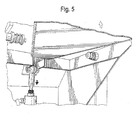
- FIG. 5 is a partial perspective view similar to FIGS. 2 and 4, but showing the actuator (retracting) moving to the stop position and the pacer plate pivoting upward, again to the stop position.
- Referring to the figures and in particular to FIG. 1, there is shown a strapping machine 10 having an integrated infeed package pacer 12 embodying the principles of the present invention. The strapping machine 10 shown is of a known type, such as the LBX-2300 Automatic Strapping Machine commercially available from ITW Signode of Glenview, Illinois.
- The strapping machine 10 includes generally, a frame 14, a strap chute 16, a strapping head 18, a strap supply or dispenser (not shown) and a control system 20. A work surface 22 is defined at the area within the chute 16 at which the strapping operation occurs (the strapping area, as indicated generally at 24)). The surface 22 can be formed as a portion of the chute 16 and can include one or more "hard" table-top like surfaces 26. The strapper 10 further includes an infeed conveyor 28, such as the illustrated belt-type conveyor. The conveyor 28 is configured to feed a load (such as a package) into the strapping area 24 for the strapping operation to occur. In such an arrangement, one or more sensors 30 can be positioned to determine the presence or absence of a package in the strapping area 24.
- The pacer 12 is mounted to the front 32 of the strapper 10, and essentially forms an integrated part of (or is integral with) the strapper 10. The pacer 12 forms an entrance to the strapper 10 and, when used in an arrangement with the feed conveyor 28, forms a bridge between the conveyor 28 and an upstream product feed or conveyor system, a portion of which is indicated at 34.
- The pacer 12 includes a frame 36 having a plurality of roller elements 38 mounted thereto to define a stationary planar conveying path 40. The path 40 aligns with (is substantially coplanar with) the strapper belt conveyor 28 and the product conveyor system 34.
- The pacer 12 includes a pacing roller element 42 that is mounted to a pivotal carriage 44. The carriage 44 pivots between a first position or feed position (FIG. 1 A) in which the pacing roller element 42 is about coplanar with the path 40 and a second or stop position (FIG. 1) in which the pacing roller 42 is moved up, above and out of the path 40. In the feed position a package moving along the product conveyor 34 will roll over the pacing roller 42 and into the strapper 10. In the stop position, the carriage 44 pivots to move the pacing roller 42 up into the conveyor path 40, to stop the package from entering the strapper 10.
- In a present pacer system 12, the pivotal carriage 44 is mounted to the pacer frame 36 by pivot pins 46. The pins 46 are mounted by springs 48 so that the pivotal carriage 44 can move slightly side-to-side to accommodate any forces that may be exerted on the pacing roller 42 (for example, when a package is on the pacer 12), and maintain the pins 46 in place.
- The pacer 12 includes a drive 50 to pivot the carriage 44. In a present system, the drive 50 is a pneumatic cylinder 52. The cylinder 52 includes a body 54 and a reciprocating rod 56. The rod 56 is mounted to the carriage 44 by a universal-type joint 58 (e.g., an eye 60 portion on the rod 56 and a pin 62 traversing the eye 60 and carriage 44) to permit the carriage 44 to freely move as the cylinder 52 reciprocates.
- The pneumatic system 64 is supplied by an air supply 66 and is controlled by the overall machine controller 20. The sensor 30 (or more than one sensor) is mounted to the machine 10 to determine the presence or absence of a package in the strapping area 24 and in the preparation area 70 just upstream from the strapping area 24. In this manner, the sensor 30 can be used to send a signal to the machine controller 20 to actuate the cylinder 52 to move the carriage 44 (and thus the pacer roller 42 into the feed or stop positions). This can be coordinated or indexed with the overall machine 10 operation.
- In an anticipated operating scheme, as a package is present in the strapping area 24, a second package is on the stationary pacer roller elements 38 and the strapper conveyor 28 (e.g., in the preparation area 70), ready to be moved into the strapping area 24. In this condition, the sensor 30 senses the presence of a package in the preparation area 70 and the pacer roller 42 is in the stop position to prevent any upstream packages from moving into the strapper 10.
- When the strapping operation is complete, the strapping machine conveyor 28 starts which moves the package in the strapping area 24 out of the strapping area 24 and moves the second package (in the preparation area 70) into the strapping area 24. As the second package moves passed the sensor 30, the sensor 30 senses the absence of a package in the strapping area 24 and the pneumatic cylinder 52 is actuated to move the pacer element 24 into the feed position. As this occurs, the packages on the product conveyor 34 all move toward the strapper 10 and a subsequent package moves into the preparation area 70. The sensor 30 senses the presence of a package in the preparation area 70 and a signal is sent to the pneumatic actuator 52 to move the pacer element 42 into the stop position. This completes one cycle.
Claims (12)
- A package pacer for use with an automatic strapping machine, the strapping machine having a strap chute through which strap material is fed and from which strap material is tensioned onto a package, the strapping machine having an in-feed conveyor defining a plane and configured to automatically move a package into a packaging region bounded by the chute, the pacer comprising:a frame, the frame mountable to the strapping machine;a plurality of rollers mounted to the frame in a stationary plane about coplanar with the in-feed conveyor plane, the rollers extending forwardly of the strapping machine, the rollers configured to permit conveyance of the package therealong and onto the in-feed conveyor;a pacing element movable between a stop position in which the pacer element is out of the in-feed conveyor plane and interferes with movement of the package onto the in-feed conveyor and a feed position in which the pacing element resides about coplanar with the planar stationary rollers and the in-feed conveyor; andmeans for moving the pacing element between the stop position and the feed position.
- The package pacer in accordance with claim 1, wherein the pacing element is a roller.
- The package pacer in accordance with claim 1, including a pacing element carriage mounted to pacer frame and configured to move the pacing element between the stop position and the feed position.
- The package pacer in accordance with claim 3, wherein the pacing element carriage is pivotally mounted to the frame.
- The package pacer in accordance with claim 1, wherein the means for moving the pacing element is a reciprocating cylinder.
- The package pacer in accordance with claim 5, wherein the cylinder is a pneumatic cylinder.
- The package pacer in accordance with claim 1, including a sensor operably connected to the moving means to sense the presence or absence of a package to generate a signal to move the pacing element between the stop position and the feed position.
- A package pacer for use with an automatic strapping machine, the strapping machine having a strap chute through which strap material is fed and from which strap material is tensioned onto a package, the strapping machine having an in-feed conveyor defining a plane and configured to automatically move a package into a packaging region bounded by the chute, the pacer comprising:a frame, the frame mountable to the strapping machine;a plurality of rollers mounted to the frame in a stationary plane about coplanar with the in-feed conveyor plane, the rollers extending forwardly of the strapping machine, the rollers configured to permit conveyance of the package therealong and onto the in-feed conveyor;a pacing roller movable between a stop position in which the pacer roller is out of the in-feed conveyor plane and interferes with movement of the package onto the in-feed conveyor and a feed position in which the pacing roller resides about coplanar with the planar stationary rollers and the in-feed conveyor;a pacing roller carriage pivotally mounted to pacer frame and configured to move the pacing roller between the stop position and the feed position;a drive operably connected to the pacing roller carriage to move the pacing roller between the stop position and the feed position.
- The package pacer in accordance with claim 8, wherein the means for moving the pacing roller is a reciprocating cylinder mounted to the carriage opposite of the pacing roller relative to the pivot.
- The package pacer in accordance with claim 8, including a sensor operably connected to the drive to sense the presence or absence of a package to generate a signal to move the pacing roller between the stop position and the feed position.
- A strapping machine configured to feed a strapping material around a load, position, tension and seal the strapping material around the load, comprising:a frame;a strap chute around which strapping material is conveyed and from which strapping material is pulled position and tension the strapping material;a driven in-feed conveyor, the in-feed conveyor defining a plane on which the load resides when the strapping material is positioned, tensioned and sealed around the load; anda package pacer having a frame mountable to the strapping machine, a plurality of rollers mounted to the frame in a stationary plane about coplanar with the in-feed conveyor plane, the rollers extending forwardly of the strapping machine, the rollers configured to permit conveyance of the load therealong and onto the in-feed conveyor, a pacing roller movable between a stop position in which the pacer roller is out of the in-feed conveyor plane and interferes with movement of the package onto the in-feed conveyor and a feed position in which the pacing roller resides about coplanar with the planar stationary rollers and the in-feed conveyor, a pacing roller carriage pivotally mounted to pacer frame and configured to move the pacing roller between the stop position and the feed position, and a drive operably connected to the pacing roller carriage to move the pacing roller between the stop position and the feed position.
- The packaging machine in accordance with claim 11, including a sensor operably connected to the drive to sense the presence or absence of a package to generate a signal to move the pacing roller between the stop position and the feed position.
Applications Claiming Priority (1)
| Application Number | Priority Date | Filing Date | Title |
|---|---|---|---|
| US11/306,981 US7270054B2 (en) | 2006-01-18 | 2006-01-18 | Integrated package pacer for strapping machine |
Publications (2)
| Publication Number | Publication Date |
|---|---|
| EP1810924A1 true EP1810924A1 (en) | 2007-07-25 |
| EP1810924B1 EP1810924B1 (en) | 2010-05-26 |
Family
ID=37898576
Family Applications (1)
| Application Number | Title | Priority Date | Filing Date |
|---|---|---|---|
| EP07100128A Not-in-force EP1810924B1 (en) | 2006-01-18 | 2007-01-04 | Integrated package pacer for strapping machine |
Country Status (3)
| Country | Link |
|---|---|
| US (1) | US7270054B2 (en) |
| EP (1) | EP1810924B1 (en) |
| DE (1) | DE602007006696D1 (en) |
Cited By (1)
| Publication number | Priority date | Publication date | Assignee | Title |
|---|---|---|---|---|
| CN103832944A (en) * | 2014-01-16 | 2014-06-04 | 合肥凯邦电机有限公司 | Lifting device for tool plate |
Families Citing this family (10)
| Publication number | Priority date | Publication date | Assignee | Title |
|---|---|---|---|---|
| CN101754917B (en) * | 2007-07-24 | 2013-04-10 | 莱特拉姆有限责任公司 | Accumulation-and-release conveyor |
| WO2012038027A1 (en) * | 2010-09-22 | 2012-03-29 | Bobst Sa | Strapping device for packaging machine |
| CH705743A2 (en) | 2011-11-14 | 2013-05-15 | Illinois Tool Works | Strapper. |
| PL3105128T3 (en) | 2014-02-10 | 2021-11-22 | Signode International Ip Holdings Llc | Strapping device having a strip feed device |
| USD864688S1 (en) | 2017-03-28 | 2019-10-29 | Signode Industrial Group Llc | Strapping device |
| CN107235442A (en) * | 2017-04-25 | 2017-10-10 | 广东天机工业智能系统有限公司 | Automatic lifting device |
| US10843883B2 (en) * | 2017-06-01 | 2020-11-24 | Usnr, Llc | Lapper assembly |
| CA192342S (en) * | 2019-07-22 | 2021-12-30 | Ergopack Deutschland Gmbh | Packaging machine |
| CN112141391B (en) * | 2020-10-19 | 2022-06-10 | 山东金号家纺集团有限公司 | A baling press for towel encapsulation |
| CN116253005A (en) * | 2023-02-07 | 2023-06-13 | 山东莱钢永锋钢铁有限公司 | Bundling mechanism for preventing bar from being jacked by steel and working method thereof |
Citations (4)
| Publication number | Priority date | Publication date | Assignee | Title |
|---|---|---|---|---|
| US3523618A (en) | 1967-08-25 | 1970-08-11 | Crisplant As | Feeder devices |
| GB2376675A (en) * | 2001-06-13 | 2002-12-24 | Tekpak Corp | Strapping machine with package detection mechanism |
| US20040099157A1 (en) | 2002-11-27 | 2004-05-27 | Illinois Tool Works, Inc. | Strapping machine having improved in-feed and out-feed |
| EP1489009A1 (en) * | 2003-06-17 | 2004-12-22 | Illinois Tool Works Inc. | Improved strap chute opening device for a strapping machine |
Family Cites Families (5)
| Publication number | Priority date | Publication date | Assignee | Title |
|---|---|---|---|---|
| US2636654A (en) * | 1949-06-03 | 1953-04-28 | Toronto Star Ltd | Conveyer control table |
| FR2568220B1 (en) * | 1984-07-27 | 1987-01-02 | Kronenbourg Brasseries | HIGH-THROUGHPUT AUTOMATIC STRAPPING MACHINE |
| US4721038A (en) * | 1986-10-22 | 1988-01-26 | Post Machinery, Inc. | Station for forming stacks of folded cartons |
| US6502373B1 (en) * | 1999-09-29 | 2003-01-07 | Illinois Tool Works Inc. | Insulation strapping machine |
| US6763930B2 (en) * | 2002-03-14 | 2004-07-20 | Rapistan Systems Advertising Corp. | Accumulation conveyor assembly |
-
2006
- 2006-01-18 US US11/306,981 patent/US7270054B2/en not_active Expired - Fee Related
-
2007
- 2007-01-04 DE DE602007006696T patent/DE602007006696D1/en active Active
- 2007-01-04 EP EP07100128A patent/EP1810924B1/en not_active Not-in-force
Patent Citations (4)
| Publication number | Priority date | Publication date | Assignee | Title |
|---|---|---|---|---|
| US3523618A (en) | 1967-08-25 | 1970-08-11 | Crisplant As | Feeder devices |
| GB2376675A (en) * | 2001-06-13 | 2002-12-24 | Tekpak Corp | Strapping machine with package detection mechanism |
| US20040099157A1 (en) | 2002-11-27 | 2004-05-27 | Illinois Tool Works, Inc. | Strapping machine having improved in-feed and out-feed |
| EP1489009A1 (en) * | 2003-06-17 | 2004-12-22 | Illinois Tool Works Inc. | Improved strap chute opening device for a strapping machine |
Cited By (2)
| Publication number | Priority date | Publication date | Assignee | Title |
|---|---|---|---|---|
| CN103832944A (en) * | 2014-01-16 | 2014-06-04 | 合肥凯邦电机有限公司 | Lifting device for tool plate |
| CN103832944B (en) * | 2014-01-16 | 2016-07-06 | 合肥凯邦电机有限公司 | The lifting device of working plate |
Also Published As
| Publication number | Publication date |
|---|---|
| EP1810924B1 (en) | 2010-05-26 |
| DE602007006696D1 (en) | 2010-07-08 |
| US20070163452A1 (en) | 2007-07-19 |
| US7270054B2 (en) | 2007-09-18 |
Similar Documents
| Publication | Publication Date | Title |
|---|---|---|
| EP2325087B1 (en) | Back-to-back bundle strapping machine | |
| US7270054B2 (en) | Integrated package pacer for strapping machine | |
| US7428865B1 (en) | Press-type strapping machine | |
| AU2002358360B2 (en) | Pack opening apparatus and method | |
| KR20190004036A (en) | Automatic packing apparatus for mask | |
| JP2000509683A (en) | Banding machine with primary and secondary tensioning units and control system therefor | |
| JPH0369414A (en) | In-line package cramping device | |
| KR101850384B1 (en) | Box sealing machine for sealing random size box | |
| CN106742310A (en) | A kind of paper lapping machine | |
| CA2401088A1 (en) | Device for packaging sheet-like folded packages | |
| AU2004201754B2 (en) | Bundling assembly for strapping machine | |
| US6851250B2 (en) | Package wrapping machine with automatic package positioning prior to wrapping | |
| KR101420577B1 (en) | Automatic bundle packing machine | |
| US20040045676A1 (en) | Synchronized stamp applicator machine and method of operating the same | |
| KR100748633B1 (en) | medicine bag conveying apparatus | |
| US6878222B1 (en) | Apparatus and method for applying indicia to packages enclosed within a container | |
| KR20200089466A (en) | Banding machine | |
| KR101242769B1 (en) | Bag compaction system | |
| CN111216970B (en) | Rice bagging-off baling equipment | |
| KR20170028550A (en) | Automatic measuring packing machine | |
| KR101367944B1 (en) | Sheet feeding device | |
| CN105501502B (en) | Dried noodle machine and its automatic feeding device | |
| JP2007106486A (en) | Horizontal pillow packaging machine | |
| FI104482B (en) | Device for dispensing packaging container blanks | |
| JPH0958606A (en) | Feeding device for tubular packaging material in bag making packaging machine |
Legal Events
| Date | Code | Title | Description |
|---|---|---|---|
| PUAI | Public reference made under article 153(3) epc to a published international application that has entered the european phase |
Free format text: ORIGINAL CODE: 0009012 |
|
| AK | Designated contracting states |
Kind code of ref document: A1 Designated state(s): AT BE BG CH CY CZ DE DK EE ES FI FR GB GR HU IE IS IT LI LT LU LV MC NL PL PT RO SE SI SK TR |
|
| AX | Request for extension of the european patent |
Extension state: AL BA HR MK YU |
|
| 17P | Request for examination filed |
Effective date: 20080114 |
|
| AKX | Designation fees paid |
Designated state(s): DE ES FR IT |
|
| 17Q | First examination report despatched |
Effective date: 20080709 |
|
| GRAP | Despatch of communication of intention to grant a patent |
Free format text: ORIGINAL CODE: EPIDOSNIGR1 |
|
| RIN1 | Information on inventor provided before grant (corrected) |
Inventor name: PEARSON, TIMOTHY B Inventor name: SICKELS, LAWRENCE G Inventor name: BOBREN, ALAN J |
|
| GRAS | Grant fee paid |
Free format text: ORIGINAL CODE: EPIDOSNIGR3 |
|
| GRAA | (expected) grant |
Free format text: ORIGINAL CODE: 0009210 |
|
| AK | Designated contracting states |
Kind code of ref document: B1 Designated state(s): DE ES FR IT |
|
| REF | Corresponds to: |
Ref document number: 602007006696 Country of ref document: DE Date of ref document: 20100708 Kind code of ref document: P |
|
| PG25 | Lapsed in a contracting state [announced via postgrant information from national office to epo] |
Ref country code: IT Free format text: LAPSE BECAUSE OF FAILURE TO SUBMIT A TRANSLATION OF THE DESCRIPTION OR TO PAY THE FEE WITHIN THE PRESCRIBED TIME-LIMIT Effective date: 20100526 |
|
| PLBE | No opposition filed within time limit |
Free format text: ORIGINAL CODE: 0009261 |
|
| STAA | Information on the status of an ep patent application or granted ep patent |
Free format text: STATUS: NO OPPOSITION FILED WITHIN TIME LIMIT |
|
| 26N | No opposition filed |
Effective date: 20110301 |
|
| REG | Reference to a national code |
Ref country code: DE Ref legal event code: R097 Ref document number: 602007006696 Country of ref document: DE Effective date: 20110228 |
|
| REG | Reference to a national code |
Ref country code: FR Ref legal event code: ST Effective date: 20110930 |
|
| PG25 | Lapsed in a contracting state [announced via postgrant information from national office to epo] |
Ref country code: FR Free format text: LAPSE BECAUSE OF NON-PAYMENT OF DUE FEES Effective date: 20110131 |
|
| REG | Reference to a national code |
Ref country code: DE Ref legal event code: R119 Ref document number: 602007006696 Country of ref document: DE Effective date: 20110802 |
|
| PG25 | Lapsed in a contracting state [announced via postgrant information from national office to epo] |
Ref country code: DE Free format text: LAPSE BECAUSE OF NON-PAYMENT OF DUE FEES Effective date: 20110802 |
|
| PG25 | Lapsed in a contracting state [announced via postgrant information from national office to epo] |
Ref country code: ES Free format text: LAPSE BECAUSE OF FAILURE TO SUBMIT A TRANSLATION OF THE DESCRIPTION OR TO PAY THE FEE WITHIN THE PRESCRIBED TIME-LIMIT Effective date: 20100906 |