EP1810914A1 - Canopy of working vehicle - Google Patents
Canopy of working vehicle Download PDFInfo
- Publication number
- EP1810914A1 EP1810914A1 EP04773045A EP04773045A EP1810914A1 EP 1810914 A1 EP1810914 A1 EP 1810914A1 EP 04773045 A EP04773045 A EP 04773045A EP 04773045 A EP04773045 A EP 04773045A EP 1810914 A1 EP1810914 A1 EP 1810914A1
- Authority
- EP
- European Patent Office
- Prior art keywords
- canopy
- seat
- frame
- roof
- pipes
- Prior art date
- Legal status (The legal status is an assumption and is not a legal conclusion. Google has not performed a legal analysis and makes no representation as to the accuracy of the status listed.)
- Withdrawn
Links
Images





Classifications
-
- B—PERFORMING OPERATIONS; TRANSPORTING
- B60—VEHICLES IN GENERAL
- B60R—VEHICLES, VEHICLE FITTINGS, OR VEHICLE PARTS, NOT OTHERWISE PROVIDED FOR
- B60R21/00—Arrangements or fittings on vehicles for protecting or preventing injuries to occupants or pedestrians in case of accidents or other traffic risks
- B60R21/02—Occupant safety arrangements or fittings, e.g. crash pads
- B60R21/11—Overhead guards, e.g. against loads falling down
-
- B—PERFORMING OPERATIONS; TRANSPORTING
- B62—LAND VEHICLES FOR TRAVELLING OTHERWISE THAN ON RAILS
- B62D—MOTOR VEHICLES; TRAILERS
- B62D33/00—Superstructures for load-carrying vehicles
- B62D33/06—Drivers' cabs
- B62D33/0617—Drivers' cabs for tractors or off-the-road vehicles
- B62D33/0625—Drivers' cabs for tractors or off-the-road vehicles open
-
- B—PERFORMING OPERATIONS; TRANSPORTING
- B60—VEHICLES IN GENERAL
- B60R—VEHICLES, VEHICLE FITTINGS, OR VEHICLE PARTS, NOT OTHERWISE PROVIDED FOR
- B60R21/00—Arrangements or fittings on vehicles for protecting or preventing injuries to occupants or pedestrians in case of accidents or other traffic risks
- B60R2021/0065—Type of vehicles
- B60R2021/0074—Utility vehicles
- B60R2021/0081—Working vehicles
-
- B—PERFORMING OPERATIONS; TRANSPORTING
- B62—LAND VEHICLES FOR TRAVELLING OTHERWISE THAN ON RAILS
- B62D—MOTOR VEHICLES; TRAILERS
- B62D27/00—Connections between superstructure or understructure sub-units
- B62D27/02—Connections between superstructure or understructure sub-units rigid
- B62D27/023—Assembly of structural joints
Definitions
- the present invention relates to a structure of a canopy arranged in a working vehicle, more specif ically, to a frame structure of the canopy having, therein, a rotatable seat.
- a work vehicle called Backhoe Loader is conventionally known in which a front loader is attached to the front part of the tractor vehicle body, and a backhoe is attached to the back part (see e.g., patent document 1).
- the operator's seat is disposed in a freely forward and backward reverse rotatable manner on the tractor vehicle body by way of a reverse rotation support device, where the operator's seat faces the front when the tractor is traveling or when using the front loader and the operator's seat faces the back when using the backhoe by the reverse rotation support device.
- the reverse rotation device of the operator's seat is configured by parallel links and a turntable.
- ROPS Roll Over Protective Structure
- the ROPS frame protects the operator from the front, back, left, right and above the operator's seat.
- the object of the present invention is to form the operator's seat to be reversely rotated in the working vehicle including the canopy, and to reduce the labor of the operator in reverse rotating the operator's seat by the shape of the safety frame of the canopy.
- the present invention relates to a canopy of a working vehicle having, therein, a rotatable seat; where frames forming the back part of the canopy are disposed radially from the rotating axis of the seat in the canopy in plan view.
- the frames forming the back part of the canopy are bent toward the inside of the canopy, and the heights of the bent point of the frames are generally aligned with the height of the seat surface of the seat disposed in the canopy.
- the present invention relates to a canopy of a working vehicle having, therein, a rotatable seat; where the canopy is formed by hollow pipes, the pipes being connected by arranging a three directional pipe joint at a connecting part of the pipes on the frames forming the canopy to form a canopy frame.
- the three directional pipe joint is formed by casting.
- a roof of the canopy is arranged on the three directional pipe joint, and a roof attachment seat of the canopy is integrally formed with the three directional pipe joint.
- the present invention relates to a canopy of a working vehicle having, therein, a rotatable seat; where a frame of the canopy is formed by four vertically arranged support columns and pipes connected to the upper ends of the four support columns to mount a roof of the canopy, the pipes for mounting the roof having a shape along a tangent line of a circumference having the rotating axis of the seat as the center.
- the present invention relates to a canopy of a working vehicle having, therein, a rotatable seat; where a frame of the canopy is formed by four support columns vertically arranged on the side part of the canopy, and pipes connected to the upper ends of the four support columns to mount a roof of the canopy; and an opening is formed at the upper end of the support column arranged at the back part of the vehicle to pass a harness into the support column.
- the present invention relates to a canopy of a working vehicle having, therein, a rotatable seat; where a frame of the canopy is formed by four vertically arranged support columns and pipes connected to the upper ends of the four support columns to mount a roof of the canopy, a plurality of pipes having the same cross sectional shape is lined and bridged across the pipes for mounting the roof to serve as reinforcement members of the pipes for mounting the roof .
- the present invention relates to a canopy of a working vehicle having, therein, a rotatable seat; where frames forming the back part of the canopy are disposed radially from the rotating axis of the seat in the canopy in plan view, and thus the space in the canopy is enlarged, the operator is able to easily rotate the seat while sitting on the seat, and the strength of the canopy is increased.
- the frames forming the back part of the canopy are bent toward the inside of the canopy, and the heights of the bent point of the frames are generally aligned with the height of the seat surface of the seat disposed in the canopy, and thus the knee etc. does not hit the frame while the operator is sitting on the seat, whereby the rotation of the seat is easily performed and the strength of the canopy is increased.
- the present invention relates to a canopy of a working vehicle having, therein, a rotatable seat; where the canopy is formed by hollow pipes, the pipes being connected by arranging a three directional pipe joint at a connecting part of the pipes on the frames forming the canopy to form a canopy frame, and thus the number of components forming the frame of the canopy is reduced, assembly is facilitated, and the manufacturing cost is reduced.
- the three directional pipe joint is formed by casting, and thus the number of components forming the frame of the canopy is reduced, assembly is facilitated, and the manufacturing cost is reduced.
- a roof of the canopy is arranged on the three directional pipe joint, and a roof attachment seat of the canopy is integrally formed with the three directional pipe join, and thus the number of components forming the frame of the canopy is reduced, and the aesthetic outer appearance of the canopy is improved.
- the present invention relates to a canopy of a working vehicle having, therein, a rotatable seat; where a frame of the canopy is formed by four vertically arranged support columns and pipes connected to the upper ends of the four support columns to mount a roof of the canopy, the pipes for mounting the roof having a shape along a tangent line of a circumference having the rotating axis of the seat as the center, and thus the support columns are more easily radially disposed in the canopy, and the strength of the canopy is easily increased.
- the present invention relates to a canopy of a working vehicle having, therein, a rotatable seat; where a frame of the canopy is formed by four support columns vertically arranged on the side part of the canopy, and pipes connected to the upper ends of the four support columns to mount a roof of the canopy; and an opening is formed at the upper end of the support column arranged at the back part of the vehicle to pass a harness into the support column, and thus the number of components configuring the canopy is reduced, a process of opening a hole for inserting the harness in the frame is unnecessary, and a well-looking canopy frame is formed with a few number of steps.
- the present invention relates to a canopy of a working vehicle having, therein, a rotatable seat; where a frame of the canopy is formed by four vertically arranged support columns and pipes connected to the upper ends of the four support columns to mount a roof of the canopy, a plurality of pipes having the same cross sectional shape is lined and bridged across the pipes for mounting the roof to serve as reinforcement members of the pipes for mounting the roof, and thus the rigidity of the frame forming the canopy is increased without increasing the types of components.
- Fig. 1 is a side view of the entire backhoe loader including a canopy.
- Fig. 1 is a side view of the entire backhoe loader including a canopy.
- the work vehicle 1 is a backhoe loader, where the loader 2 serving as a loading device and a drilling device 3 are attached to the work vehicle 1.
- a bracket 4 is arranged on both left and right sides of the bonnet of the work vehicle 1, which bracket 4 is fixed to the vehicle body frame of the work vehicle 1.
- a canopy 5 is arranged on the vehicle body frame, and the operator operates the work vehicle in the canopy 5.
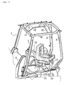
- Fig. 2 is a plan view showing the frame structure of the canopy
- Fig. 3 is a side view of the same
- Fig. 4 is a perspective view of the same
- Fig. 5 is a plan view showing the structure of the top frame.
- the canopy 5 is configured by front frames 7, 7, rear frames 8, 8, a top frame 16, and a front top frame 17.
- the front frame 7, the rear frame 8, the top frame 16, and the front top frame 17 are formed by square pipes, so that each frame is easily molded, and members are easily connected and arranged to each frame.
- the front frames 7, 7 and the rear frames 8, 8 are respectively connected by the top frame 16 at the upper end.
- the top frame 16 is formed into a U-shape in plan view, and an opening is formed facing the front side, which the opening side of the top frame 16 is closed by bridging the front top frame 17.
- the front frames 7, 7, the top frame 16 and the front top frame 17 are connected by two joints 15, 15.
- a roof 6 is arranged on the top frame 16.
- a reinforcement frame 18 is arranged in the left and right direction at the center of the top frame 16, and a top plate 19 is arranged between the front top frame 17 and the reinforcement frame 18.
- the roof 6 is arranged on the top plate 19.
- the canopy 5 is attached to the vehicle body frame 12 of the work vehicle, and the lower ends of the front frames 7 and the rear frames 8 are fixed to the vehicle body frame 12 arranged in the front and back direction of the work vehicle.
- a seat 9 on which the operator sits and the operation unit 10 of the work machine are arranged in the canopy 5, the seat 9 being positioned at approximately the center in the canopy 5.
- the operation unit 10 is positioned on the side of the seat 9.
- the operation unit 10 is attached to the vehicle body frame 12, and operation tools of the work machine such as operation lever is arranged at the upper part of the operation unit 10.
- the seat 9 is arranged by way of a seat pillar 11 on a beam 13 bridged between the vehicle body frames 12, 12 arranged on the left and the right.
- the seat pillar 11 is positioned on the shaft center of the rotation shaft 9b of the seat 9, the seat pillar 11 supporting the seat 9 in a freely rotatable manner. The operator rotates the seat 9 while sitting on the seat 9 and reversely rotates the seat 9 from the front towards the back or from the back towards the front.
- the front frames 7 are arranged in the up and down direction at the front part of the canopy 5.
- the front frames 7 are arranged with the upper ends tilted towards the rear side, and the lower parts of the front frames 7 are also fixed to the bracket 4 for supporting the front loader of the work vehicle.
- the rear frames 8 are arranged in the up and down direction at the back part of the canopy 5.
- the rear frames 8 have a configuration having the lower parts extended diagonally upward towards the rear side at the back part of the canopy 5, bent to a dogleg shape and then extended diagonally slightly towards the front side from the direction of immediately above.
- the bent point 8t of the rear frame 8 has a structure approximately aligned with the height 9h of the seat surface of the seat 9, so that the foot space of the operator sitting on the seat 9 is ensured.
- the bent point 8t of the rear frame 8 Since the bent point 8t of the rear frame 8 is positioned at the height 9h of the seat surface of the seat 9, the bent point 8t most distant from the seat 9 in the rear frame 8 becomes equal to the position of the knee of the operator sitting on the seat 9.
- the rear frames 8 avoid the knee of the operator when the seat 9 is reversely rotated, thereby facilitating the reverse rotation while sitting on the seat 9.
- the rear frame 8 has a square cross section when seen in plan view, the flat surface on the seat 9 side (side facing the seat) of the rear frame 8 is substantially orthogonal to the line connecting the rotating shaft 9b of the seat 9 and the rear frame 8, and the flat surface on the seat 9 side of the rear frame 8 is substantially parallel to the tangent line of a circle having the rotating shaft 9b as the center at the arrangement position of the rear frame 8. Therefore, the projection towards the seat 9 of the frame 8 is eliminated, and the operator is less likely to hit the frame 8 with his/her leg when reversely rotating the seat 9.
- the flat surface on the seat 9 side of the rear frame 8 is a flat surface in the longitudinal side in cross sectional view of the square pipe forming the rear frame 8, and thus resistance force in the front and back direction and left and right direction, and furthermore, in the twist direction is exhibited by arranging the rear frame 8.
- the foot space of the operator is ensured, the operator is able to rotate the seat 9 while sitting thereon, and the strength of the canopy 5 is increased since the frame 8 is radially arranged with the rotating shaft 9b of the seat 9 as the center in plan view.
- the rigidity is exhibited to the force in the traverse direction and the load in the front and back direction applied to the canopy 5 by arranging the rear frame 8 in the above manner.
- the frame for fixing the lower ends of the frames 8 must be extended to the rear side, and the strength in the left and right (or front and back) direction becomes inferior to the front and back (or left and right) direction. If the foot space is formed to be accommodated within the same left and right width, the space becomes narrower than in the present invention.
- the top frame 16 is formed into a shape that lies substantially along the tangent line of the circumference of the rotation of the seat 9, and configures the surface facing the back, surfaces facing the left and the right, and the surface diagonally facing the rear side at the back part of the canopy 5 .
- the rear frames 8 canbe easily arranged radially from the rotating center of the seat 9, the connection between the rear frame 8 and the top frame 16 is facilitated, and the connection between the rear frames 8 and the top frame 16 is easily performed by configuring the top frame 16 in such manner.
- the rear frame 8 is arranged radially with respect to the seat 9 in plan view, the concave side portion of the bent rear frame 8 is faced towards the seat 9, and the back part of the top frame 16 is formed into a circumferential shape that aligns with the rotating center of the seat 9, and thus the volume of the canopy 5 is increased, the distance between the frames is shortened, and a sufficient rigidity is provided to the canopy 5. That is, the canopy 5 can be miniaturized while enhancing the interior comfort of the canopy 5.
- Fig. 6 is a side view of the joint arranged at the upper right part of the canopy
- Fig. 7 is a perspective view of the joint arranged at the upper left part of the canopy
- Fig. 8 is a view of the roof viewed diagonally from the rear side
- Fig. 9 is a perspective view viewed diagonally from the front side showing an attachment structure of the roof by the joint.
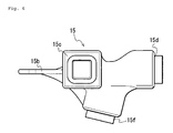
- the joint 15 is arranged to connect the frames extending in three directions at the upper front part of the canopy 5, the joint 15 connecting the front frame 7, the top frame 16, and the front top frame 17.
- the upper end of the front frame 7, the front end of the top frame 16, and the side end of the front top frame 17 are connected to the joint 15.
- the joint 15 is configured by a lower connecting part 15f, a rear connecting part 15d, a traverse connecting part 15c and a stay 15b.
- the lower connecting part 15f is formed diagonally downward towards the front side
- the rear connecting part 15d is formed towards the rear side
- the traverse connecting part 15c is formed towards the side.
- the stay 15b extends from the upper surface of the corner towards the front side in the horizontal direction as an attachment seat of the roof 6.
- the joint 15 is formed through casting, where fine angular adjustment in the joint 15 can be easily realized by cast.
- the frame of the canopy 5 can be assembled at high accuracy, and the manufacturing cost can be reduced.
- the front frame 7 is connected to the lower connecting part 15f, the top frame 16 to the rear connecting part 15d, the front top frame 17 to the traverse connecting part 15c, and the front part of the roof 6 arranged on the top frame 16 is attached to the stay 15b.
- the joint 15 includes a three directional pipe joint, where a step portion is arranged at each of the lower connecting part 15f, the rear connecting part 15d, and the traverse connecting part 15c, which are the pipe joints.
- the pipe joint portion is formed so that the diameter (cross sectional area) on the distal end side is small, and the pipes configuring the frame of the canopy are attached to the distal end side. That is, the pipe joint portion has a shape that complies with the inner shape of the pipe shaped frame of the canopy.
- connection of the frames is easily performed by fitting the pipes configuring the frame to the lower connecting part 15f, the rear connecting part 15d and the traverse connecting part 15c.
- the structure of the connecting part of each frame can be simplified by forming the coupling portions of the pipes to be coupled at a complex angle with the joint 15, or the molded article. Manufacturing is thus easily realized with reduced number of components of welded structure, reduced labor for positioning etc. in time of welding, and enhanced assembly of the canopy
- the roof 6 is arranged on the joint 15, and the front part of the roof 6 is fixed by the stay 15b of the joint 15.
- the stay 15b extends horizontally towards the outward front side in the diagonal direction from the joint 15.
- a hole opened in the up and down direction is formed in the stay 15b, where a bolt is inserted and fitted to the hole to fix the roof 6 to the joint 15.
- the number of components configuring the canopy 5 are reduced, the portion to be welding is reduced and the assembly is enhanced since the roof 6 is attached by means of the stay 15b integrally formed with the joint 15 for connecting the frames configuring the canopy 5.
- the aesthetic appearance of the canopy 5 is thereby also enhanced. In terms of workability, the vision in the canopy 5 is less likely to be inhibited by the joint 15, and a satisfactory vision is ensured since the sites that project downward are reduced at the joint 15 disposed at the upper front part of the canopy 5.
- Fig. 10 is a cross sectional side view of the roof and Fig. 11 is a perspective view showing the structure of the lower surface of the roof.
- the roof 6 is arranged on the frame of the canopy 5.
- the roof 6 forms a concave part having the lower side opened at the center of the lower surface, and the top frame 16 and the front top frame 17 are arranged along the inner side of the periphery of the roof 6.
- the reinforcement frame 18 bridged in the left and right direction is formed by lining two square pipes in the front and back direction at the middle in the front and back direction between left and right top frames 16, and the two pipes are coupled to each other through welding.
- the reinforcement frame 18 is welded and fixed to the top frame 16 at both ends.
- the square pipe configuring the reinforcement frame 18 is the same square pipe configuring the top frame 16, and thus dimensional adjustment in time of connection is easily performed.
- the frame of the upper part of the canopy 5 is inexpensively reinforced, and the rigidity of the structure can be enhanced without increasing the type of constituting members.
- the reinforcement frame 18 has an arch shape projecting upward from the top frame 16 at the middle in the left and right direction, where the upper surface at the middle part in the left and right direction of the reinforcement frame 18 and the upper surface at the middle part in the left and right direction of the of the front top frame 17 are connected by a top plate 19, thus also contributing to reinforcement.
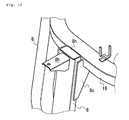
- Fig. 12 is a view showing an opening of the rear frame.
- the top frame 16 has a polygonal shape similar to the circumference having the rotating axis of the seat 9 as the center, and the rear frame 8 is fixed to the outer surface of the top frame 16 through welding.
- a bracket 8c is attached to the rear frame 8, thereby increasing the rigidity of the connection with the top frame 16.
- a stay 8b diagonally extending to the rear side is attached to the upper end of the rear frame 8.
- the back part of the roof 6 is fixed by the stay 8b. That is, the roof 6 is fixed to the frame of the canopy 5 configuring the safety frame, thereby reducing oscillation of the roof 6 and improving silence in traveling.
- the upper end of the rear frame 8 is opened upward, and the wirings of electrical components such as illumination arranged at the upper part of the canopy 5 are passed to the rear frame 8 through the opening on the upper end.
- the harness is protected by the rear frame 8, a process of opening a hole for passing the harness in the upper part of the rear frame 8 is not necessary, fixation along the frame is not necessary, and a frame of satisfactory appearance is realized with a small number of processing.
- the upper end of the rear frame 8 is fixed through welding to the outer surface at a position coinciding with the upper surface of the top frame 16, and thus the contacting surface of the rear frame and the top frame is large, whereby the rigidity of connection is high, the dimension error in assembling the frame is absorbed in the connection of the frame 16 and the rear frame 8, and the labor required in manufacturing is reduced.
- the space in the canopy can be enlarged, and thus workability in reverse rotating the operator's seat in the working vehicle is extensively enhanced.
Landscapes
- Engineering & Computer Science (AREA)
- Mechanical Engineering (AREA)
- Chemical & Material Sciences (AREA)
- Combustion & Propulsion (AREA)
- Transportation (AREA)
- Body Structure For Vehicles (AREA)
- Component Parts Of Construction Machinery (AREA)
Abstract
Description
- The present invention relates to a structure of a canopy arranged in a working vehicle, more specif ically, to a frame structure of the canopy having, therein, a rotatable seat.
- A work vehicle called Backhoe Loader is conventionally known in which a front loader is attached to the front part of the tractor vehicle body, and a backhoe is attached to the back part (see e.g., patent document 1). In the backhoe loader, the operator's seat is disposed in a freely forward and backward reverse rotatable manner on the tractor vehicle body by way of a reverse rotation support device, where the operator's seat faces the front when the tractor is traveling or when using the front loader and the operator's seat faces the back when using the backhoe by the reverse rotation support device. The reverse rotation device of the operator's seat is configured by parallel links and a turntable. ROPS (Roll Over Protective Structure) frame, which is a safety frame, is arranged in the vicinity of the operator's seat. The ROPS frame protects the operator from the front, back, left, right and above the operator's seat.
[Patent document 1] Japanese Laid-Open Patent Publication No.5-229377 - However, in the tractor disclosed in patent document 1, the space between the operator's seat and the safety frame is narrow, and thus is troublesome when the operator reverse operates the operator's seat and again sits on the operator's seat. The workability of when reverse rotating the operator' s seat is thus low. In particular, in the tractor in which the canopy is formed around the operator's seat, the knee tends to hit the canopy frame and the operator must adjust oneself when rotating the operator's seat while sitting thereon in rotating the operator's seat to reverse rotate the same.
- The object of the present invention is to form the operator's seat to be reversely rotated in the working vehicle including the canopy, and to reduce the labor of the operator in reverse rotating the operator's seat by the shape of the safety frame of the canopy.
- The present invention relates to a canopy of a working vehicle having, therein, a rotatable seat; where frames forming the back part of the canopy are disposed radially from the rotating axis of the seat in the canopy in plan view.
- In the present invention, the frames forming the back part of the canopy are bent toward the inside of the canopy, and the heights of the bent point of the frames are generally aligned with the height of the seat surface of the seat disposed in the canopy.
- The present invention relates to a canopy of a working vehicle having, therein, a rotatable seat; where the canopy is formed by hollow pipes, the pipes being connected by arranging a three directional pipe joint at a connecting part of the pipes on the frames forming the canopy to form a canopy frame.
- In the present invention, the three directional pipe joint is formed by casting.
- In the present invention, a roof of the canopy is arranged on the three directional pipe joint, and a roof attachment seat of the canopy is integrally formed with the three directional pipe joint.
- The present invention relates to a canopy of a working vehicle having, therein, a rotatable seat; where a frame of the canopy is formed by four vertically arranged support columns and pipes connected to the upper ends of the four support columns to mount a roof of the canopy, the pipes for mounting the roof having a shape along a tangent line of a circumference having the rotating axis of the seat as the center.
- The present invention relates to a canopy of a working vehicle having, therein, a rotatable seat; where a frame of the canopy is formed by four support columns vertically arranged on the side part of the canopy, and pipes connected to the upper ends of the four support columns to mount a roof of the canopy; and an opening is formed at the upper end of the support column arranged at the back part of the vehicle to pass a harness into the support column.
- The present invention relates to a canopy of a working vehicle having, therein, a rotatable seat; where a frame of the canopy is formed by four vertically arranged support columns and pipes connected to the upper ends of the four support columns to mount a roof of the canopy, a plurality of pipes having the same cross sectional shape is lined and bridged across the pipes for mounting the roof to serve as reinforcement members of the pipes for mounting the roof .
- The present invention relates to a canopy of a working vehicle having, therein, a rotatable seat; where frames forming the back part of the canopy are disposed radially from the rotating axis of the seat in the canopy in plan view, and thus the space in the canopy is enlarged, the operator is able to easily rotate the seat while sitting on the seat, and the strength of the canopy is increased.
- In the present invention, the frames forming the back part of the canopy are bent toward the inside of the canopy, and the heights of the bent point of the frames are generally aligned with the height of the seat surface of the seat disposed in the canopy, and thus the knee etc. does not hit the frame while the operator is sitting on the seat, whereby the rotation of the seat is easily performed and the strength of the canopy is increased.
- The present invention relates to a canopy of a working vehicle having, therein, a rotatable seat; where the canopy is formed by hollow pipes, the pipes being connected by arranging a three directional pipe joint at a connecting part of the pipes on the frames forming the canopy to form a canopy frame, and thus the number of components forming the frame of the canopy is reduced, assembly is facilitated, and the manufacturing cost is reduced.
- In the present invention, the three directional pipe joint is formed by casting, and thus the number of components forming the frame of the canopy is reduced, assembly is facilitated, and the manufacturing cost is reduced.
- In the present invention, a roof of the canopy is arranged on the three directional pipe joint, and a roof attachment seat of the canopy is integrally formed with the three directional pipe join, and thus the number of components forming the frame of the canopy is reduced, and the aesthetic outer appearance of the canopy is improved.
- The present invention relates to a canopy of a working vehicle having, therein, a rotatable seat; where a frame of the canopy is formed by four vertically arranged support columns and pipes connected to the upper ends of the four support columns to mount a roof of the canopy, the pipes for mounting the roof having a shape along a tangent line of a circumference having the rotating axis of the seat as the center, and thus the support columns are more easily radially disposed in the canopy, and the strength of the canopy is easily increased.
- The present invention relates to a canopy of a working vehicle having, therein, a rotatable seat; where a frame of the canopy is formed by four support columns vertically arranged on the side part of the canopy, and pipes connected to the upper ends of the four support columns to mount a roof of the canopy; and an opening is formed at the upper end of the support column arranged at the back part of the vehicle to pass a harness into the support column, and thus the number of components configuring the canopy is reduced, a process of opening a hole for inserting the harness in the frame is unnecessary, and a well-looking canopy frame is formed with a few number of steps.
- The present invention relates to a canopy of a working vehicle having, therein, a rotatable seat; where a frame of the canopy is formed by four vertically arranged support columns and pipes connected to the upper ends of the four support columns to mount a roof of the canopy, a plurality of pipes having the same cross sectional shape is lined and bridged across the pipes for mounting the roof to serve as reinforcement members of the pipes for mounting the roof, and thus the rigidity of the frame forming the canopy is increased without increasing the types of components.
- Fig. 1 is a side view of the entire backhoe loader including a canopy.
- Fig. 2 is a plan view showing a frame structure of a canopy.
- Fig. 3 is a side view showing a frame structure of a canopy.
- Fig. 4 is a perspective view showing a frame structure of a canopy.
- Fig. 5 is a plan view showing a structure of a top frame.
- Fig. 6 is a side view of a joint arranged on the upper right part of the canopy.
- Fig. 7 is a perspective view of the joint arranged on the upper left part of the canopy.
- Fig. 8 is a view of a roof viewed diagonally from the rear side.
- Fig. 9 is a perspective view viewed diagonally from the front side showing an attachment structure of the roof by the joint.
- Fig. 10 is a cross sectional side view of the roof.
- Fig. 11 is a perspective view showing the structure of the lower surface of the roof.
- Fig. 12 is a view showing an opening of the rear frame.
-
- 1
- working vehicle
- 2
- loader
- 3
- drilling device
- 4
- bracket
- 5
- canopy
- 6
- roof
- 7
- front frame
- 8
- rear frame
- 9
- seat
- 10
- operation unit
- 11
- seat pillar
- 12
- vehicle body frame
- 13
- beam
- 15
- joint
- 16
- top frame
- 17
- front top frame
- 18
- reinforcement frame
- 19
- top plate
- An example of the present invention will now be described using the figures. Fig. 1 is a side view of the entire backhoe loader including a canopy. The work vehicle 1 is a backhoe loader, where the
loader 2 serving as a loading device and adrilling device 3 are attached to the work vehicle 1. A bracket 4 is arranged on both left and right sides of the bonnet of the work vehicle 1, which bracket 4 is fixed to the vehicle body frame of the work vehicle 1. A canopy 5 is arranged on the vehicle body frame, and the operator operates the work vehicle in the canopy 5. - The structure of the frame configuring the canopy will now be described using Figs. 2 to 4. Fig. 2 is a plan view showing the frame structure of the canopy, Fig. 3 is a side view of the same, Fig. 4 is a perspective view of the same, and Fig. 5 is a plan view showing the structure of the top frame. The canopy 5 is configured by
front frames rear frames top frame 16, and a fronttop frame 17. Thefront frame 7, therear frame 8, thetop frame 16, and the fronttop frame 17 are formed by square pipes, so that each frame is easily molded, and members are easily connected and arranged to each frame. The front frames 7, 7 and therear frames top frame 16 at the upper end. Thetop frame 16 is formed into a U-shape in plan view, and an opening is formed facing the front side, which the opening side of thetop frame 16 is closed by bridging the fronttop frame 17. The front frames 7, 7, thetop frame 16 and the fronttop frame 17 are connected by twojoints roof 6 is arranged on thetop frame 16. Areinforcement frame 18 is arranged in the left and right direction at the center of thetop frame 16, and atop plate 19 is arranged between the fronttop frame 17 and thereinforcement frame 18. Theroof 6 is arranged on thetop plate 19. - The canopy 5 is attached to the
vehicle body frame 12 of the work vehicle, and the lower ends of thefront frames 7 and therear frames 8 are fixed to thevehicle body frame 12 arranged in the front and back direction of the work vehicle. Aseat 9 on which the operator sits and theoperation unit 10 of the work machine are arranged in the canopy 5, theseat 9 being positioned at approximately the center in the canopy 5. Theoperation unit 10 is positioned on the side of theseat 9. Theoperation unit 10 is attached to thevehicle body frame 12, and operation tools of the work machine such as operation lever is arranged at the upper part of theoperation unit 10. Theseat 9 is arranged by way of aseat pillar 11 on abeam 13 bridged between the vehicle body frames 12, 12 arranged on the left and the right. Theseat pillar 11 is positioned on the shaft center of therotation shaft 9b of theseat 9, theseat pillar 11 supporting theseat 9 in a freely rotatable manner. The operator rotates theseat 9 while sitting on theseat 9 and reversely rotates theseat 9 from the front towards the back or from the back towards the front. - The front frames 7 are arranged in the up and down direction at the front part of the canopy 5. The front frames 7 are arranged with the upper ends tilted towards the rear side, and the lower parts of the
front frames 7 are also fixed to the bracket 4 for supporting the front loader of the work vehicle. The rear frames 8 are arranged in the up and down direction at the back part of the canopy 5. The rear frames 8 have a configuration having the lower parts extended diagonally upward towards the rear side at the back part of the canopy 5, bent to a dogleg shape and then extended diagonally slightly towards the front side from the direction of immediately above. Thebent point 8t of therear frame 8 has a structure approximately aligned with theheight 9h of the seat surface of theseat 9, so that the foot space of the operator sitting on theseat 9 is ensured. Since thebent point 8t of therear frame 8 is positioned at theheight 9h of the seat surface of theseat 9, thebent point 8t most distant from theseat 9 in therear frame 8 becomes equal to the position of the knee of the operator sitting on theseat 9. Thus, therear frames 8 avoid the knee of the operator when theseat 9 is reversely rotated, thereby facilitating the reverse rotation while sitting on theseat 9. - The
rear frame 8 has a square cross section when seen in plan view, the flat surface on theseat 9 side (side facing the seat) of therear frame 8 is substantially orthogonal to the line connecting therotating shaft 9b of theseat 9 and therear frame 8, and the flat surface on theseat 9 side of therear frame 8 is substantially parallel to the tangent line of a circle having therotating shaft 9b as the center at the arrangement position of therear frame 8. Therefore, the projection towards theseat 9 of theframe 8 is eliminated, and the operator is less likely to hit theframe 8 with his/her leg when reversely rotating theseat 9. The flat surface on theseat 9 side of therear frame 8 is a flat surface in the longitudinal side in cross sectional view of the square pipe forming therear frame 8, and thus resistance force in the front and back direction and left and right direction, and furthermore, in the twist direction is exhibited by arranging therear frame 8. The foot space of the operator is ensured, the operator is able to rotate theseat 9 while sitting thereon, and the strength of the canopy 5 is increased since theframe 8 is radially arranged with therotating shaft 9b of theseat 9 as the center in plan view. The rigidity is exhibited to the force in the traverse direction and the load in the front and back direction applied to the canopy 5 by arranging therear frame 8 in the above manner. That is, if theframe 8 is configured standing at both rear corners, the frame for fixing the lower ends of theframes 8 must be extended to the rear side, and the strength in the left and right (or front and back) direction becomes inferior to the front and back (or left and right) direction. If the foot space is formed to be accommodated within the same left and right width, the space becomes narrower than in the present invention. - The
top frame 16 is formed into a shape that lies substantially along the tangent line of the circumference of the rotation of theseat 9, and configures the surface facing the back, surfaces facing the left and the right, and the surface diagonally facing the rear side at the back part of the canopy 5 . The rear frames 8 canbe easily arranged radially from the rotating center of theseat 9, the connection between therear frame 8 and thetop frame 16 is facilitated, and the connection between therear frames 8 and thetop frame 16 is easily performed by configuring thetop frame 16 in such manner. Therear frame 8 is arranged radially with respect to theseat 9 in plan view, the concave side portion of the bentrear frame 8 is faced towards theseat 9, and the back part of thetop frame 16 is formed into a circumferential shape that aligns with the rotating center of theseat 9, and thus the volume of the canopy 5 is increased, the distance between the frames is shortened, and a sufficient rigidity is provided to the canopy 5. That is, the canopy 5 can be miniaturized while enhancing the interior comfort of the canopy 5. - The configuration of the joint 15 will now be described. Fig. 6 is a side view of the joint arranged at the upper right part of the canopy, Fig. 7 is a perspective view of the joint arranged at the upper left part of the canopy, Fig. 8 is a view of the roof viewed diagonally from the rear side, and Fig. 9 is a perspective view viewed diagonally from the front side showing an attachment structure of the roof by the joint. The joint 15 is arranged to connect the frames extending in three directions at the upper front part of the canopy 5, the joint 15 connecting the
front frame 7, thetop frame 16, and the fronttop frame 17. The upper end of thefront frame 7, the front end of thetop frame 16, and the side end of the fronttop frame 17 are connected to the joint 15. The joint 15 is configured by a lower connectingpart 15f, arear connecting part 15d, atraverse connecting part 15c and astay 15b. The lower connectingpart 15f is formed diagonally downward towards the front side, therear connecting part 15d is formed towards the rear side, and thetraverse connecting part 15c is formed towards the side. Thestay 15b extends from the upper surface of the corner towards the front side in the horizontal direction as an attachment seat of theroof 6. The joint 15 is formed through casting, where fine angular adjustment in the joint 15 can be easily realized by cast. Thus, the frame of the canopy 5 can be assembled at high accuracy, and the manufacturing cost can be reduced. - The
front frame 7 is connected to the lower connectingpart 15f, thetop frame 16 to therear connecting part 15d, the fronttop frame 17 to thetraverse connecting part 15c, and the front part of theroof 6 arranged on thetop frame 16 is attached to thestay 15b. The joint 15 includes a three directional pipe joint, where a step portion is arranged at each of the lower connectingpart 15f, therear connecting part 15d, and thetraverse connecting part 15c, which are the pipe joints. The pipe joint portion is formed so that the diameter (cross sectional area) on the distal end side is small, and the pipes configuring the frame of the canopy are attached to the distal end side. That is, the pipe joint portion has a shape that complies with the inner shape of the pipe shaped frame of the canopy. Thus, the connection of the frames is easily performed by fitting the pipes configuring the frame to the lower connectingpart 15f, therear connecting part 15d and thetraverse connecting part 15c. The structure of the connecting part of each frame can be simplified by forming the coupling portions of the pipes to be coupled at a complex angle with the joint 15, or the molded article. Manufacturing is thus easily realized with reduced number of components of welded structure, reduced labor for positioning etc. in time of welding, and enhanced assembly of the canopy - The
roof 6 is arranged on the joint 15, and the front part of theroof 6 is fixed by thestay 15b of the joint 15. Thestay 15b extends horizontally towards the outward front side in the diagonal direction from the joint 15. A hole opened in the up and down direction is formed in thestay 15b, where a bolt is inserted and fitted to the hole to fix theroof 6 to the joint 15. The number of components configuring the canopy 5 are reduced, the portion to be welding is reduced and the assembly is enhanced since theroof 6 is attached by means of thestay 15b integrally formed with the joint 15 for connecting the frames configuring the canopy 5. The aesthetic appearance of the canopy 5 is thereby also enhanced. In terms of workability, the vision in the canopy 5 is less likely to be inhibited by the joint 15, and a satisfactory vision is ensured since the sites that project downward are reduced at the joint 15 disposed at the upper front part of the canopy 5. - The configuration of the
roof 6 will now be described. Fig. 10 is a cross sectional side view of the roof and Fig. 11 is a perspective view showing the structure of the lower surface of the roof. Theroof 6 is arranged on the frame of the canopy 5. Theroof 6 forms a concave part having the lower side opened at the center of the lower surface, and thetop frame 16 and the fronttop frame 17 are arranged along the inner side of the periphery of theroof 6. Thereinforcement frame 18 bridged in the left and right direction is formed by lining two square pipes in the front and back direction at the middle in the front and back direction between left and right top frames 16, and the two pipes are coupled to each other through welding. Thereinforcement frame 18 is welded and fixed to thetop frame 16 at both ends. The square pipe configuring thereinforcement frame 18 is the same square pipe configuring thetop frame 16, and thus dimensional adjustment in time of connection is easily performed. Thus, the frame of the upper part of the canopy 5 is inexpensively reinforced, and the rigidity of the structure can be enhanced without increasing the type of constituting members. - The
reinforcement frame 18 has an arch shape projecting upward from thetop frame 16 at the middle in the left and right direction, where the upper surface at the middle part in the left and right direction of thereinforcement frame 18 and the upper surface at the middle part in the left and right direction of the of the fronttop frame 17 are connected by atop plate 19, thus also contributing to reinforcement. - The attachment of harness in the
rear frame 8 will now be described. Fig. 12 is a view showing an opening of the rear frame. Thetop frame 16 has a polygonal shape similar to the circumference having the rotating axis of theseat 9 as the center, and therear frame 8 is fixed to the outer surface of thetop frame 16 through welding. Abracket 8c is attached to therear frame 8, thereby increasing the rigidity of the connection with thetop frame 16. Astay 8b diagonally extending to the rear side is attached to the upper end of therear frame 8. The back part of theroof 6 is fixed by thestay 8b. That is, theroof 6 is fixed to the frame of the canopy 5 configuring the safety frame, thereby reducing oscillation of theroof 6 and improving silence in traveling. The upper end of therear frame 8 is opened upward, and the wirings of electrical components such as illumination arranged at the upper part of the canopy 5 are passed to therear frame 8 through the opening on the upper end. Thus, the harness is protected by therear frame 8, a process of opening a hole for passing the harness in the upper part of therear frame 8 is not necessary, fixation along the frame is not necessary, and a frame of satisfactory appearance is realized with a small number of processing. In configuring the canopy 5, the upper end of therear frame 8 is fixed through welding to the outer surface at a position coinciding with the upper surface of thetop frame 16, and thus the contacting surface of the rear frame and the top frame is large, whereby the rigidity of connection is high, the dimension error in assembling the frame is absorbed in the connection of theframe 16 and therear frame 8, and the labor required in manufacturing is reduced. - In the canopy of the working vehicle of the present invention, the space in the canopy can be enlarged, and thus workability in reverse rotating the operator's seat in the working vehicle is extensively enhanced.
Claims (8)
- A canopy of a working vehicle having, therein, a rotatable seat; wherein
frames forming the back part of the canopy are disposed radially from the rotating axis of the seat in the canopy in plan view. - The canopy of the working vehicle according to claim 1, wherein the frames forming the back part of the canopy are bent toward the inside of the canopy, and the heights of the bent point of the frames are generally aligned with the height of the seat surface of the seat disposed in the canopy.
- A canopy of a working vehicle having, therein, a rotatable seat; wherein
the canopy is formed by hollow pipes, the pipes being connected by arranging a three directional pipe joint at a connecting part of the pipes on the frames forming the canopy to form a canopy frame. - The canopy of the working vehicle according to claim 3, wherein the three directional pipe joint is formed by casting.
- The canopy of the working vehicle according to claim 3 or 4, wherein a roof of the canopy is arranged on the three directional pipe joint, and a roof attachment seat of the canopy is integrally formed with the three directional pipe joint.
- A canopy of a working vehicle having, therein, a rotatable seat; wherein
a frame of the canopy is formed by fourverticallyarranged support columns and pipes connected to the upper ends of the four support columns to mount a roof of the canopy, the pipes for mounting the roof having a shape along a tangent line of a circumference having the rotating axis of the seat as the center. - A canopy of a working vehicle having, therein, a rotatable seat; wherein
a frame of the canopy is formed by four support columns vertically arranged on the side part of the canopy, and pipes connected to the upper ends of the four support columns to mount a roof of the canopy; and an opening is formed at the upper end of the support column arranged at the back part of the vehicle to pass a harness into the support column. - A canopy of a working vehicle having, therein, a rotatable seat; wherein
a frame of the canopy is formed by fourverticallyarranged support columns and pipes connected to the upper ends of the four support columns to mount a roof of the canopy, a plurality of pipes having the same cross sectional shape is lined and bridged across the pipes for mounting the roof to serve as reinforcement members of the pipes for mounting the roof.
Applications Claiming Priority (2)
| Application Number | Priority Date | Filing Date | Title |
|---|---|---|---|
| JP2004244474A JP4257276B2 (en) | 2004-08-24 | 2004-08-24 | Backhoe loader canopy |
| PCT/JP2004/013372 WO2006022033A1 (en) | 2004-08-24 | 2004-09-14 | Canopy of working vehicle |
Publications (2)
| Publication Number | Publication Date |
|---|---|
| EP1810914A1 true EP1810914A1 (en) | 2007-07-25 |
| EP1810914A4 EP1810914A4 (en) | 2008-01-23 |
Family
ID=35967256
Family Applications (1)
| Application Number | Title | Priority Date | Filing Date |
|---|---|---|---|
| EP04773045A Withdrawn EP1810914A4 (en) | 2004-08-24 | 2004-09-14 | Canopy of working vehicle |
Country Status (4)
| Country | Link |
|---|---|
| US (1) | US7631927B2 (en) |
| EP (1) | EP1810914A4 (en) |
| JP (1) | JP4257276B2 (en) |
| WO (1) | WO2006022033A1 (en) |
Families Citing this family (12)
| Publication number | Priority date | Publication date | Assignee | Title |
|---|---|---|---|---|
| FR2899197B1 (en) * | 2006-04-04 | 2009-03-20 | Jean Naud | VEHICLE HABITACLE WITH ADAPTABLE OPENING |
| US8485589B2 (en) * | 2010-03-30 | 2013-07-16 | Kubota Corporation | Cabin system |
| DE102011105556B4 (en) * | 2011-06-25 | 2023-04-13 | Abg Allgemeine Baumaschinen-Gesellschaft Mbh | road construction machine |
| US8851555B2 (en) * | 2013-02-07 | 2014-10-07 | Caterpillar Inc. | Cab rollover protective structure for enhanced visibility |
| US8702154B1 (en) * | 2013-02-07 | 2014-04-22 | Caterpillar Inc. | Cab frame with integrated rollover protective structure |
| US9315219B2 (en) * | 2013-10-18 | 2016-04-19 | Yanmar Co., Ltd. | Tractor |
| DE102015012560A1 (en) * | 2014-10-07 | 2016-04-07 | Bomag Gmbh | Control station for a construction machine and construction machine with a control station |
| US9855972B2 (en) * | 2015-04-16 | 2018-01-02 | Ford Global Technologies, Llc | Vehicle roof with truss structure |
| US9849919B2 (en) | 2015-12-08 | 2017-12-26 | Ford Global Technologies, Llc | Vehicle roof structure |
| IT202100008540A1 (en) * | 2021-04-06 | 2022-10-06 | Manitou Italia Srl | TELEHANDLER WITH EASY GETTING UP AND DOWN. |
| JP7555319B2 (en) * | 2021-09-21 | 2024-09-24 | 株式会社クボタ | ROPS FRAME FOR WORK VEHICLE AND WORK VEHICLE |
| USD1116978S1 (en) * | 2022-02-02 | 2026-03-10 | The Toro Company | Shade |
Family Cites Families (12)
| Publication number | Priority date | Publication date | Assignee | Title |
|---|---|---|---|---|
| DE1267109B (en) * | 1965-12-17 | 1968-04-25 | Fritzmeier Kg Georg | Roll-over protection frame for mobile machines, especially tractors |
| FR2261164A1 (en) * | 1974-02-15 | 1975-09-12 | Ffsa | Versatile self powered agricultural machine - drivers cabin slides and can face front or rear, implement front or rear |
| GB1561940A (en) * | 1977-11-03 | 1980-03-05 | Versatile Mfg Ltd | Reversible seat and steering console for tracotrs |
| US5086869A (en) * | 1990-08-14 | 1992-02-11 | Ford New Holland, Inc. | Rotatable operator control station |
| US5036942A (en) | 1990-08-14 | 1991-08-06 | Ford New Holland, Inc. | Rotatable operator control unlocking mechanism |
| US5052512A (en) * | 1990-08-14 | 1991-10-01 | Ford New Holland, Inc. | Reversible control level linkage |
| JP2984592B2 (en) | 1995-12-11 | 1999-11-29 | 新キャタピラー三菱株式会社 | Cabin for construction machinery |
| JP4113925B2 (en) | 2000-01-19 | 2008-07-09 | ヤンマー株式会社 | Backhoe cabin |
| JP4321975B2 (en) | 2001-05-23 | 2009-08-26 | 株式会社クボタ | Working vehicle structure |
| JP4397147B2 (en) | 2002-07-10 | 2010-01-13 | 株式会社小松製作所 | Working vehicle cab |
| JP2004042739A (en) * | 2002-07-10 | 2004-02-12 | Komatsu Ltd | Driver's cab in work vehicle |
| JP2004161114A (en) | 2002-11-12 | 2004-06-10 | Hitachi Constr Mach Co Ltd | Cab for construction machine |
-
2004
- 2004-08-24 JP JP2004244474A patent/JP4257276B2/en not_active Expired - Fee Related
- 2004-09-14 EP EP04773045A patent/EP1810914A4/en not_active Withdrawn
- 2004-09-14 US US11/574,229 patent/US7631927B2/en not_active Expired - Fee Related
- 2004-09-14 WO PCT/JP2004/013372 patent/WO2006022033A1/en not_active Ceased
Also Published As
| Publication number | Publication date |
|---|---|
| US7631927B2 (en) | 2009-12-15 |
| JP4257276B2 (en) | 2009-04-22 |
| WO2006022033A1 (en) | 2006-03-02 |
| EP1810914A4 (en) | 2008-01-23 |
| JP2006062423A (en) | 2006-03-09 |
| US20080007090A1 (en) | 2008-01-10 |
Similar Documents
| Publication | Publication Date | Title |
|---|---|---|
| EP2186665B1 (en) | Rear door structure | |
| US7131687B2 (en) | Work vehicle | |
| US7631927B2 (en) | Canopy of working vehicle | |
| US7665801B2 (en) | Structure of upper frame for supporting cabin of construction machinery | |
| EP3756987A1 (en) | Leaning vehicle | |
| KR100652086B1 (en) | Cap for construction machinery | |
| EP1602563B1 (en) | Rops canopy of hydraulic shovel | |
| US20060017308A1 (en) | Driver's cabin of construction machine | |
| EP2749479B1 (en) | Kick-up frame connection structure | |
| KR100602666B1 (en) | Steering column fixing panel of cowl crossmember | |
| CN110937024B (en) | Steering support structure | |
| JP2000309946A (en) | Canopy support structure for rotating working vehicle | |
| JP4156987B2 (en) | Cab interior reinforcement structure | |
| JP3514055B2 (en) | Mounting structure of suspension lower link | |
| EP4023819B1 (en) | Working machine | |
| JPH0710996Y2 (en) | Steering column device | |
| JPH0710998Y2 (en) | Steering column device | |
| JP2012126309A (en) | Hood latch mounting structure | |
| US20240400137A1 (en) | First joining member, second joining member, and joining structure | |
| JP2004076455A (en) | Revolving construction machine | |
| JP5716583B2 (en) | Vehicle seat frame structure | |
| KR100440311B1 (en) | a mounting structure of front shock absorber and upper arm in vehicles | |
| JP6102965B2 (en) | Boom foot part of work machine | |
| JP2025134456A (en) | Pipe nut fixing structure | |
| JP6090353B2 (en) | Boom foot part of work machine |
Legal Events
| Date | Code | Title | Description |
|---|---|---|---|
| PUAI | Public reference made under article 153(3) epc to a published international application that has entered the european phase |
Free format text: ORIGINAL CODE: 0009012 |
|
| 17P | Request for examination filed |
Effective date: 20070326 |
|
| AK | Designated contracting states |
Kind code of ref document: A1 Designated state(s): DE FR GB IT |
|
| DAX | Request for extension of the european patent (deleted) | ||
| RBV | Designated contracting states (corrected) |
Designated state(s): DE FR GB IT |
|
| A4 | Supplementary search report drawn up and despatched |
Effective date: 20071227 |
|
| RIC1 | Information provided on ipc code assigned before grant |
Ipc: B62D 25/08 20060101AFI20060321BHEP Ipc: B62D 1/22 20060101ALI20071218BHEP |
|
| RBV | Designated contracting states (corrected) |
Designated state(s): DE FR GB IT |
|
| 17Q | First examination report despatched |
Effective date: 20080624 |
|
| STAA | Information on the status of an ep patent application or granted ep patent |
Free format text: STATUS: THE APPLICATION IS DEEMED TO BE WITHDRAWN |
|
| 18D | Application deemed to be withdrawn |
Effective date: 20140401 |