EP1810793A1 - Cassette type stapler - Google Patents
Cassette type stapler Download PDFInfo
- Publication number
- EP1810793A1 EP1810793A1 EP04793267A EP04793267A EP1810793A1 EP 1810793 A1 EP1810793 A1 EP 1810793A1 EP 04793267 A EP04793267 A EP 04793267A EP 04793267 A EP04793267 A EP 04793267A EP 1810793 A1 EP1810793 A1 EP 1810793A1
- Authority
- EP
- European Patent Office
- Prior art keywords
- slider
- handle
- guide
- guide portion
- swaying member
- Prior art date
- Legal status (The legal status is an assumption and is not a legal conclusion. Google has not performed a legal analysis and makes no representation as to the accuracy of the status listed.)
- Withdrawn
Links
Images


Classifications
-
- B—PERFORMING OPERATIONS; TRANSPORTING
- B25—HAND TOOLS; PORTABLE POWER-DRIVEN TOOLS; MANIPULATORS
- B25C—HAND-HELD NAILING OR STAPLING TOOLS; MANUALLY OPERATED PORTABLE STAPLING TOOLS
- B25C5/00—Manually operated portable stapling tools; Hand-held power-operated stapling tools; Staple feeding devices therefor
- B25C5/02—Manually operated portable stapling tools; Hand-held power-operated stapling tools; Staple feeding devices therefor with provision for bending the ends of the staples on to the work
- B25C5/0221—Stapling tools of the table model type, i.e. tools supported by a table or the work during operation
- B25C5/0242—Stapling tools of the table model type, i.e. tools supported by a table or the work during operation having a pivoting upper leg and a leg provided with an anvil supported by the table or work
- B25C5/025—Stapling tools of the table model type, i.e. tools supported by a table or the work during operation having a pivoting upper leg and a leg provided with an anvil supported by the table or work the plunger being manually operated
-
- B—PERFORMING OPERATIONS; TRANSPORTING
- B25—HAND TOOLS; PORTABLE POWER-DRIVEN TOOLS; MANIPULATORS
- B25C—HAND-HELD NAILING OR STAPLING TOOLS; MANUALLY OPERATED PORTABLE STAPLING TOOLS
- B25C5/00—Manually operated portable stapling tools; Hand-held power-operated stapling tools; Staple feeding devices therefor
- B25C5/10—Driving means
- B25C5/11—Driving means operated by manual or foot power
Definitions
- the present invention relates to a stapler which, when stapling a sheet bundle composed of a plurality of sheets stacked together by means of a staple, can clinch the leg portions of the staple flat along the lower surface of the sheet bundle, that is, a flat clinch type stapler.
- stapling is effected in two stages: a stage in which the leg portions of the staple penetrate the sheet bundle, and a stage in which the leg portions having penetrated the sheet bundle are flinched.
- the first stage by pushing down a handle, the handle and a staple box containing staples are brought close to each other.
- a blade provided on the inner side of the handle pushes out a staple in the staple box, and the leg portions of the staple penetrate the sheet bundle.
- the member receiving the sheets is prevented from descending by a member (slider) preventing descent of the swaying member, and the blade cannot reach the anvil.
- the stapler is restored to the state before the operation; that is, the slider is caused to advance to relatively ascend the swaying member, restoring the state in which descent of the swaying member is prevented.
- the advancement of the slider and the ascent of the swaying member in this process are effected by providing a mechanism which is separate from the mechanism for lowering the swaying member and which uses a coil spring, a plate spring, etc.
- the motion of the handle is transmitted to the slider by way of a plurality of components added to the handle, frame, magazine, etc.
- the handle descent motion is transmitted to the slider; in the mechanism for raising the swaying member, there are used a plurality of springs, pins, and rivets.
- the flat clinch type stapler Although popular in the market, the flat clinch type stapler involves a rather complicated construction and a large number of indispensable components as stated above, inevitably resulting in a complicated manufacturing process and high product price, which constitute an obstacle to its sufficiently widespread use.
- Another object of the present invention is to provide a stapler which is of a simple construction as described above and which only involves a small number indispensable components, thereby making it possible to provide a product that is easy to manufacture and of low price in the market.
- Still another object of the present invention is to provide a product which is relatively free from failure owing to the simple construction and the small number of components.
- a further object of the present invention is to provide a product which helps to maintain a stable stapling performance.
- a still further object of the present invention is to provide a product in which the number of components is reduced to thereby make it possible to reduce the time required to maintain the requisite level of component precision.
- a stapler including: a base mechanism equipped with an anvil mechanism; a staple box mechanism rotatably mounted to the base mechanism; a handle mechanism rotatably mounted to the base mechanism, situated above the stable boxmechanism, and equipped with a blade; and a flat clinch mechanism, the flat clinch mechanism having a swaying member and a slider, the slider existing under the swaying member to prevent descent of the swaying member while leg portions of a staple contained in the staple box mechanism penetrate a sheet bundle through descent of the blade, descent prevention for the swaying member being canceled by displacing the slider from under the swaying member, the blade pushing out, through descent of the swaying member, the staple such that forward ends of the leg portions of the staple having penetrated the sheet bundle reach the position where the anvil mechanism exists, the staple binding the sheet bundle through clinching of the leg portions of the staple through engagement of the leg portions of the staple with the anvil mechanism,
- the stapleboxmechanism refers toabox-shapedmechanism loaded with staples.
- the present invention is applicable to both of the following systems; one in which the box is provided in the stapler main body and in which when the staples have been consumed, the box is newly loaded with staples alone; and one in which a holder for receiving the box is provided in the staple main body and in which when the staples have been consumed, a box loaded with staples is introduced in its entirety into the holder, that is, the cassette type system.
- the present invention features a special flat clinching mechanism, in particular, a special sliding mechanism for the slider. That is, the slider slides in one longitudinal direction on the base, whereby the descent prevention for the swaying member is canceled, and the swaying member is allowed to descend.
- this sliding of the slider is effected by providing the slider with a spring, etc. dedicated to the sliding of the slider.
- the means for sliding the slider in one direction and the means for sliding it in the other direction are formed by a single mechanism which converts vertical motion of the handle to longitudinal motion of the slider.
- one direction refers, for example, to the forward direction, in which case the other direction refers to the backward direction.
- the other direction refers to the forward direction.
- the vertical motion of the handle implies the motion generated when the user grasping the handle pushes it down to use the stapler and the motion generated when the handle is raised by a handle spring.
- Such vertical motion is converted to longitudinal motion of the slider by a single mechanism. Owing to the single mechanism, when the handle is further raised by the handle spring, this vertical motion is converted to a longitudinal motion of the slider by the single mechanism, and the slider slides on the base to return to the former position.
- the return of the slider to the former position means the return of the slider to the position where descent of the swaying member is prevented.
- the problems are solved by the stapler the stapler according to the first aspect of the invention, characterized in that the handle is provided with a first handle guide portion and a second handle guide portion, that the slider is provided with a first slider guide portion and a second slider guide portion, that, in the one mechanism, through descent of the handle, the first handle guide portion and the first slider guide portion are engaged with each other and the descending motion of the handle is converted to a motion causing the slider to slide in one direction, and that, through ascent of the handle, the second handle guide portion and the second slider guide portion are engaged with each other and the ascending motion of the handle is converted to a motion causing the slider to slide in the other direction.
- the first handle guide portion is a portion which, when the handle descends, transmits the descending motion to the slider and which is indicated by, for example, reference numerals 37 (Fig. 2), 89 (Fig. 19), and 96 (Fig. 27) referred to below.
- the descending motion of the handle is received by the first slider guide portion as indicated by, for example, reference numerals 21 (Fig. 3), 74 (Fig. 18), and 109 (Fig. 26) referred to below.
- the first handle guide portion When the handle starts to descend, the first handle guide portion is first engaged with the first slider guide portion. Further, the first handle guide portion continues to impart a force causing the slider to descend through the descent of the handle.
- the first handle guide member has a distinctive guide surface, and the motion in the direction in which the handle descends is converted to a motion in the direction in which the slider moves backwards.
- the second handle guide portion is a portion which, when the handles ascends, transmits the ascending motion to the slider, and which is indicated by, for example, reference numerals 36 (Fig. 2), 90 (Fig. 21), and 97 (Fig. 27) referred to below.
- the ascending motion of the handle is received by the second slider guide portion as indicated by, for example, reference numerals 20 (Fig. 14), 79 (Fig. 21), 114 (Fig. 26), and 115 (Fig. 34) referred to below.
- the second handle guide portion When the handle starts to ascend, the second handle guide portion is first engaged with the second slider guide portion. Further, the second handle guide portion continues to impart a force causing a protruding member to ascend through the ascent of the handle.
- the second handle guide member has a distinctive guide surface, and the motion in the direction in which the protruding member ascends is converted to a mot ion in the direction in which the slider moves forwards.
- the first handle guide portion and the second handle guide portion may be provided as spaces in the handle itself, or may be provided so as to protrude from the right-hand side surface and the left-hand side surface of the handle. They may also be provided on a leg portion of the handle.
- the configuration of the first handle guide portion and the second handle guide portion may, for example, be rectangular or circular.
- the slider guide portion and the second handle guide portion may be provided directly in the slider main body portion in the form of cutouts or protrusions.
- the problems are solved by the stapler according to the second aspect of the invention, characterized in that both the first handle guide portion and the second handle guide portion are provided on a leg portion of the handle, and that both the first slider guide portion and the second slider guide portion are surfaces provided on the slider.
- the leg portion of the handle is a member protruding downwards from the handle like a leg.
- the configuration of the leg portion is not restricted to a rectangular one; it may also be triangular, spherical, etc.
- the configuration of the slider guide portion is in conformity with the configuration of the leg portion so as to allow engagement of the first handle guide portion with the first slider portion, and engagement of the second handle portion with the second slider portion.
- the problems are solved by the stapler according to the third aspect of the invention, characterized in that the first handle guide portion is a rear end of a lower end of the leg portion of the handle, that the second handle guide portion is a front end of the lower end of the leg portion of the handle, that the first slider guide portion is a front surface of a first protrusion provided at a rear of the slider, and that the second slider guide portion is a rear surface of a second protrusion provided at the rear of the slider.
- the leg portion is of a boot-like configuration.
- the boot heel portion constitutes the first handle guide portion, and the boot toe portion constitutes the second handle guide portion.
- the corner portions of those guide portions it is desirable for the corner portions of those guide portions not to be sharp but rounded.
- two pairs of upwardly extending protrusions are arranged longitudinally.
- the rear surface of the front protrusion constitutes the second slider guide portion, and the front surface of the rear protrusion constitutes the first slider guide portion.
- the positions and configuration of these two pairs of protrusions and the configuration of the leg portion of the handle convert vertical motion of the handle to longitudinal motion of the slider.
- the problems are solved by the stapler according to the second aspect of the invention, characterized in that the first handle guide portion and the second handle guide portion are formed by an inner peripheral surface of an opening provided in the handle, and that the first slider guide portion and the second slider guide portion exist on a protruding portion of a protruding member engaged with a stopper one end of which is fixed to the slider and the other end of which is fixed to the base.
- the inner peripheral surface of the opening provided in the handle is of a distinctive configuration; this configuration converts vertical motion of the handle to longitudinal motion of the slider.
- the "protruding member” is of a configuration whose central portion protrudes, such as an arcuate one or an Inverted V-shaped one.
- the “protruding portion of the protruding member” means the central portion in the case of an arcuate configuration, and the crest of an Inverted V-shaped chevron in the case of an Inverted V-shaped member.
- the problems are solved by the stapler according to the fifth aspect of the invention, characterized in that the first handle guide portion is an upper surface of the inner peripheral surface of the opening, that the second handle guide portion is a lower surface of the inner peripheral surface of the opening, and that the protruding member is an Inverted V-shaped member, with the first slider guide portion existing at the external angle of the apex of the Inverted V-shaped member, and the second slider guide portion existing at the internal angle of the apex of the Inverted V-shaped member.
- the bent portion refers to the apex portion of the Inverted V-shaped member.
- One end of the Inverted V-shaped member is fixed to the slider, and the other end of the Inverted V-shaped member is a free end, and this free end portion is engaged with the stopper fixed to the base.
- the outer side of the apex of the Inverted V-shaped member is engaged with the first handle guide portion as the first slider guide portion, and receives a downwardly directed force.
- the other end of the Inverted V-shaped member is engaged with the stopper fixed to the base, the downwardly directed force escapes in the direction of one end of the Inverted V-shaped member fixed to the slider. As a result, the slider slides backwards on the base.
- the second slider portion is borne by the inside portion of the apex of the Inverted V-shaped member.
- the second handle guide portion is engaged with the second slider portion, and tries to lift the Inverted V-shaped member as the handle ascends.
- the lifting motion is converted to a motion causing the slider to slide forwards on the base.
- the problems are solved by the stapler according to the fifth aspect of the invention, characterized in that the stopper exists in front of the protruding member, and that a downward motion of the handle is converted to a motion causing the slider to slide backwards.
- the positions of one end of the Inverted V-shaped member fixed to the slider and the other end thereof engaged with the stopper are longitudinally reversed from those according to the sixth aspect of the invention.
- the downward motion of the handle is converted to a motion causing the slider to slide backwards
- the vertical motion of the handle is converted to a motion causing the slider to slide forwards.
- the problems are solved by the stapler according to the fourth or seventh aspect of the invention, characterized in that the a swaying member guide is provided in front of and below the swaying member, that, when the slider slides backwards on the base, a front upper end of the slider moves along the swaying member guide, the swaying member descending to a lowermost position when the front upper end of the slider is situated at the rear end of the swaying member guide, and that, when the slider slides forwards on the base, the front upper end of the slider moves along the swaying member guide, the slider preventing descent of the swaying member when the front upper end of the slider is situated on the front side of the forward end of the swaying member guide.
- the swaying member guide is a guide surface by which a corner of the slider is guided when the prevention by the slider is canceled and the swaying member descends. It is necessary for the configuration of this surface to be one suitable for effecting the descent smoothly. Depending on the length of the staple legs, the descending distance differs; this also indicates that there are various configurations suitable for smooth descent.
- the swaying member guide may be configured into a convex surface, a concave surface, or a sigma-shaped surface.
- Such a guide surface may be provided not on the swaying member but on the slider.
- a ninth aspect of the present invention describes the case in which it is provided on the slider.
- the problems are solved by the stapler according to the fourth or seventh aspect of the invention, characterized in that a slider guide is provided above the forward end of the slider, that, when the slider slides backwards on the base, a guide end provided in front of and below the swaying member moves along the slider guide, the swaying member descending to a lowermost position when the guide end is situated at the forward end of the slider guide, and that, when the slider slides forwards on the base, the guide end moves along the slider guide, the slider preventing descent of the swaying member when the guide end is situated on the rear side of the slider guide.
- the problems are solved by the stapler according to the fifth aspect of the invention, characterized in that the stopper exists at a rear of the protruding member, and that a downward motion of the handle is converted to a motion causing the slider to slide forwards.
- the problems are solved by the stapler according to the tenth aspect of the invention, characterized in that a slider guide is provided above a front end of the slider, that, when the slider slides forwards on the base, a guide end provided in front of and below the swaying member moves along the slider guide, the swaying member descending to a lowermost position when the guide end is situated at the front end of the slider guide, and that, when the slider slides backwards on the base, the guide end moves along the slider guide, the swaying member preventing descent of the slider when the guide member is situated on the rear side of the rear end of the slider guide.
- the problems are solved by the stapler according to the first aspect of the invention, characterized in that the handle is equipped with a first handle guide portion and a second handle guide portion, that the slider is equipped with a first slider guide portion and a second slider guide portion, that, in the single mechanism, through descent of the handle, the first handle guide portion and the first slider guide portion are engaged with each other through a handle-slider guide member to convert the descending motion of the handle to a motion causing the slider to slide backwards, and that, through ascent of the handle, the second handle guide portion and the second slider guide portion are engaged with each other through the handle-slider guide member to convert the ascending motion of the handle to a motion causing the slider to slide forwards.
- the invention according to the twelfth aspect of the invention is characterized in that the first and second handle guide members and the first and second slider guide members are engaged through the intermediation of the handle-slider guide member, which is a separate member.
- the invention according to the twelfth aspect of the invention is characterized in that the degree of freedom in the design of the stapler is enhanced.
- the leg length of the handle-slider guide member is adjusted by the principles of the lever, whereby it is possible to increase or reduce the sliding distance of the slider.
- the magnitude of the handle stroke and the magnitude of the force to be imparted to the handle can be adjusted through the leg length, so it is possible to achieve a high degree of freedom in design.
- the present invention is easily applicable to various staplers ranging from small staplers to large staplers for stapling thick sheet bundles.
- the problems are solved by the stapler according to the twelfth aspect of the invention, characterized in that the handle-slider guide member is rotatably fixed to a base column provided on the base, that the first handle guide portion and the second handle guide portion are formed by an inner peripheral surface of an opening provided in the handle, that one end of the handle-slider guide member is engaged with the inner peripheral surface, that the first slider guide member and the second slider guide member exist in a cutout provided in the slider, and that the other end of the handle-slider guide member is engaged with the cutout.
- the inner peripheral surface of the opening provided in the handle is of a distinctive configuration, and one end of the handle-slider guide member is engaged with the inner peripheral surface to be guided by a path along the inner peripheral surface, so the vertical motion of the handle is converted to the longitudinal motion of the slider.
- the user experiences a snapping shock when the swaying member is detached from the holder.
- a shock is substantiallymitigated.
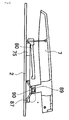
- Figs. 1 through 13 show Embodiment 1.
- contact between the handle leg and the slider rear portion converts the descending motion of the handle to longitudinal sliding motion of the slider.
- the slider slides backwards, and the guide surface for gently lowering the swaying member is provided on the swaying member.
- the side of the stapler as seen in the long-axis direction where the blade exists is referred to as the front side, and the side thereof where the handle and the base are rotatably fixed is referred to as the rear side; the side where the handle exists is referred to as the upper side and the side where the base exists is referred to as the lower side; and the right-hand side and the left-hand side are those as seen from above.
- a stapler 1 is composed of a base 2, a slider 4, a swaying member 5, a base cover 3, a staple case 8, a frame 6, and a handle 7.
- a handle spring 40 is provided inside the handle, and urges the handle away from the frame.
- a base spring 43 is provided under the frame, urging the base away from the frame.
- a staple case spring 42 At the rear of the staple case, there is provided a staple case spring 42, urging the staple case so as to push it forwards.
- an anvil base 10 is provided on the front portion of the base 2, and an iron anvil 11 is fitted in at this position.
- the slider 4 has a recess 16 in its front portion.
- the recess 16 is provided for the purpose of keeping off from the anvil 11 for stapling when the stapler is assembled.
- the slider 4 has a recess 22 in its rear portion.
- the recess 22 is provided for the purpose of keeping off from the swaying member base 12 when the stapler is assembled.
- a handle leg guide mechanism for guiding the handle leg. That is, there are provided handle leg guides 18 extending upwards, and handle leg guides 19 extending upwards likewise. Guide surfaces 20 and 21, formed by the leg guide, guide handle legs 35 as described below.
- the slider 4 is placed on the base such that its right and left outer walls extend along the slider guides 14 of the base 2.
- the swaying member 5 has a leg 25 in the rear portion thereof.
- the leg 25 has a hole 26.
- the hole 26 corresponds to the swaying member support shafts 13 provided on the swaying member base 12 on the base 2 (Fig. 4).
- Figs. 6 through 12 show changes in the positional relationship between the handle, the swaying member, and the slider at the time of stapling.
- Fig. 13 is an explanatory partial sectional view showing changes in the positional relationship at the time of stapling including changes in the positional relationship of the staple case.
- leg front ends 36 of the handle legs 35 are engaged with the guide surfaces 20 of the handle leg guides 18 of the slider 4, so the slider 4 is at the foremost position; at this time, descent of the swaying member 5 is prevented.
- the slider 4 When the handle is further lowered as shown in Fig. 9, the slider 4 further slides backwards, and descends along the curve provided on the lower surface of the swaying member. When the swaying member is brought to the lowermost position, the staple is clinched flat along the back surface of the sheet. At this time, the stapler is in the state as shown in portion E of Fig. 13.
- the handle As shown in Fig. 10, by releasing the handle, the handle is raised by the handle spring (Fig. 1) ; when the handle is raised, the front leg ends 36 of the handle legs 35 push the guide surfaces 20 of the slider 4 forwards, and the slider 4 slides forwards a little.
- Embodiment 1 provides the following effects.
- the slider and the swaying member are constantly held in contact with each other by virtue of the guide surfaces provided on the swaying member, so no shock or noise is generated. Further, the operation of the swaying member is adjusted to the kind of staple, the length of the staple legs, the hardness of the staple, etc., so an optimum flat clinching effect is to be expected, making it possible to provide a stapler of a satisfactory stapling performance.
- the swaying member is rotatably supported by a bearing integrally formed on the base, so no such components as a pin is required, with the result that the assembly is facilitated, and the stapler is made less subject to failure.
- the slider is simply placed on the base 2, so the assembly is facilitated, and the stapler is made less subject to failure.
- Reliable positioning for the slider is established by a slider guide integrally formed on the base or a guide device of perfect accuracy integrally formed on the bases such as the anvil base and the swaying member base, so it is possible to automatically effect a stable sliding.
- the sliding distance of the slider can be adjusted easily, so the design of a product in conformity with staple leg length is facilitated.
- Embodiment 2 is the same as Embodiment 1 in that it adopts a mechanism for converting vertical motion of the handle to longitudinal motion of the slider; it differs from Embodiment 1 in that the guide surface for gently lowering the swaying member is provided not on the swaying member but on the slider.
- Embodiment 2 provides the following effects.
- Embodiment 3 adopts a mechanism formed by a stopper provided on the base and an Inverted V-shaped member provided on the slider. Further, at the time of clinching, the slider slides backwards, and the guide surface for gently lowering the swaying member is provided on the swaying member.
- each Inverted V-shaped member 76 is mounted to the rear end of a slider 75.
- the forward end of each Inverted V-shaped member 76 is a free end.
- a stopper 82 is fixed to the base 2, and the slider 75 is placed at a position such that the forward, free end of the Inverted V-shaped member is held in contact with the stopper 82. Further, when the slider is placed on the base 2, the swaying member mounted on the base is held in contact with the slider at the position as shown in Figs. 18 and 22.
- the swaying member is rotatably fixed to the base cover 3 at a position indicated by numeral 112. While Fig. 26 shows Embodiment 4, the positional relationship between the swaying member and the base cover is the same in Embodiment 3 and Embodiment 4.
- FIGs. 19 through 25 sequentially illustrate the mechanism of the stapler of Embodiment 3 at the time of operation.
- a recess 88 is formed by a handle guide member 87 provided on the handle member 7, and a guide shaft 79 formed of an Inverted V-shaped member is engaged with the recess 88.
- the apex of the Inverted V-shaped member 74 is engaged with an upper inner wall 89 of the recess 88, whereby a force is exerted so as to spread the legs of the Inverted V-shaped member.
- the front end of the Inverted V-shaped member is engaged with the stopper 82 of the base 2, and the Inverted V-shaped member is mounted to the slider 75, whereby the slider 75 slides backwards on the base 2 (Figs. 19 through 21) to lower the swaying member (Fig. 22) .
- a lower inner wall 90 of the recess 88 and the Inverted V-shaped guide member 79 are engaged with each other, and, as the handle member ascends, a force is exerted so as to bring the distal ends of the legs of the Inverted V-shaped member closer to each other, and the slider 75 slides forwards on the base 2 (Figs. 23 and 24), and the swaying member 80 is placed on the slider 75 again (Fig. 25).
- Embodiment 3 provides the following effects.
- the movement of the slider can be made light and smooth.
- the width of the slider movement can be easily adjusted according to the angle of the Inverted V-shapedportion of the Inverted V-shaped member. That is, the width of the movement of the slider depends upon the staple leg length, that is, the thickness of the object to be stapled. Thus, the force with which the slider is caused to slide can be made large or small according to the angle of the Inverted V-shaped portion of the Inverted V-shaped member.
- Embodiment 4 is the same as Embodiment 3 in that it employs a mechanism for converting vertical motion of the handle to longitudinal motion of the slider; it differs from Embodiment 3 in the positional relationship between the stopper and the slider. Owing to this difference, at the time of clinching, the slider slides forwards.
- the guide surface for lowering the swaying member is provided on the slider.
- Figs. 27 through 33 sequentially illustrate the stapler mechanism of Embodiment 4 at the time of operation. That is, a recess 95 is formed owing to the handle guide member provided on the handle member 7, and the recess 95 is engaged with a guide shaft 94 provided near the apex 109 of the Inverted V-shaped member. By pushing down the handle 7, the apex 109 of the Inverted V-shaped member is engaged with an upper inner wall 96 of the recess 95, whereby a force is exerted so as to spread the legs of the Inverted V-shaped member.
- the rear end of the Inverted V-shaped member is engaged with a stopper 113 on the base 2, and the Inverted V-shaped member is mounted to the slider 99, whereby the slider 99 slides forwards on the base 2 (Figs. 31 through 33), causing the swaying member to descend (Fig. 31). After this, as the handle member ascends, the slider 99 slides backwards on the base 2 (Figs. 32 and 33), and the swaying member 98 is placed on the slider 99 again (Fig. 27).
- Embodiment 4 provides the following effect: Since the guide surface of the slider and the forward end of the bottom surface of the swaying member move while in contact with each other, the slider moves smoothly forwards. Since the guide surface of the slider and the forward end of the bottom surface of the swaying member are constantly held in contact with each other, no shock or noise is generated until the completion of stapling.
- Embodiment 5 is the same as Embodiment 4 in that it employs a mechanism (the Inverted V-shaped member 107, the stopper 82, etc.) for converting vertical motion of the handle to longitudinal motion of the slider; it differs from Embodiment 4 in that the guide surface for gently lowering the swaying member is provided on the slider.
- a mechanism the Inverted V-shaped member 107, the stopper 82, etc.
- Embodiment 5 at the time of completion of stapling, the forward end of a slider 106 causes a swaying member 105 to descend gently and smoothly, and the bottom surface of the swaying member is gently received by the forward end, so there is no need to provide a cushion member or the like.
- the rear bottom surface of the swaying member is constantly held in contact with the slider, so there is generated no shock until the swaying member reaches the lowermost point; thus, no uncomfortable noise is generated, and a smooth operation is always to be expected.
- Embodiment 6 employs an arm mechanism; at the time of clinching, the slider slides backwards, and the guide surface for gently lowering the swaying member is provided on the swaying member.
- an arm 69 is equipped with a pair of upper arms 66, a central arm 68, and a lower arm 69 engaged with the slider.
- the slider 60 has recesses 61, 62 similar to those of the slider of Embodiment 1. That is, the positional relationship between the slider and the swaying member is the same as that in Embodiment 1; the recess 61 is a recess for mounting the swaying member to the base 2, and the recess 62 is a recess for an anvil base.
- Arm supports 55 are provided on the base 2, and holes 56 of the arm supports 55 are engaged with the arm.
- an arm support 63 At the rear of the slider 60, there is provided an arm support 63, which is engaged with the lower arm 69.
- the handle 7 is equipped with a handle guide member 70, and a space 71 is provided between it and the handle 7.
- An arm guide shaft 67 is engaged with the space 71.
- the positional relationship between the arm guide shaft 67 and the space 71 of the handle guide member 70 when the handle 7 is rotated is as shown in Figs. 46 through 49, and the corresponding positional relationship between the slider 60 and the swaying member 58 is as shown in Figs. 40 through 45. That is, by downwardly rotating the handle, the slider 60 slides backwards (Fig. 42), and, by further rotating the handle downwardly to cause the slider 60 to slide backwards, the engagement between the slider 60 and the swaying member 58 is canceled, and the swaying member 58 descends (Fig. 44). By upwardly rotating the handle, the arm causes the slider 60 to slide forwards (Fig. 45), with the result that the swaying member is placed on the slider, and the state prior to the operation is restored (Fig. 40).
- the handle guide member 70 is mounted so as to protrude sidewise with respect to the handle 7.
- the upwardly facing surface of the handle guide member 70 constitutes a lower guide surface 73
- the downwardly facing surface of the handle 7 constitutes an upper guide surface 72. That is, the upper surface of the upper arm 66 is in contact with the upper guide surface 72, and the lower surface of the guide shaft 67 protruding sidewise from the arm 66 is in contact with the lower guide surface 73 of the space 71.
- Embodiment 6 provides the following specific effects. Since the arm utilizes the principles of the lever, the arm can transmit the movement of the handle to the slider smoothly and lightly.
- the movement of the handle is transmitted to the slider through the arm.
- the movement width of the slider can be enlarged, so the embodiment is also applicable to long-leg staples for thick paper sheets.
- Embodiment 6 is advantageous in that it makes it possible to achieve a higher degree of freedom in terms of stapler design.
- the handle-slider guide member owing to the principles of the lever, it is possible to cause the slider to slide greatly by small movement of the handle. Further, it is possible to cause the slider to slide to a small degree by a great movement of the handle.
- this embodiment can be easily applicable to various designs from a small size stapler to a large size stapler for stapling thick sheet bundles.
- the position of the handle guide member can be freely changed in the longitudinal direction.
- Embodiment 7 adopts an arm member mechanism; at the time of clinching, the slider slides backwards, and the guide surface for gently lowering the swaying member is provided on the slider.
- the effect obtained by using a separate member, that is, the arm member mechanism, is the same as that of Embodiment 6.
- the guide surface is provided on the slider, so the descent and ascent of the sliding member can be made light and smooth and quiet, with the impact sound being reduced.
- the present invention is to be utilized in the flat clinching mechanism of a flat clinch type stapler.
Landscapes
- Engineering & Computer Science (AREA)
- Mechanical Engineering (AREA)
- Portable Nailing Machines And Staplers (AREA)
Abstract
Description
- The present invention relates to a stapler which, when stapling a sheet bundle composed of a plurality of sheets stacked together by means of a staple, can clinch the leg portions of the staple flat along the lower surface of the sheet bundle, that is, a flat clinch type stapler.
- The following documents disclose flat clinch type staplers.
- [0003] [Patent Document 1]
Japanese Utility Model Application Laid-open No. Sho 62-35779 - [Patent Document 2]
Japanese Utility Model Application Laid-open No. Sho 62-35780 - [Patent Document 3]
Japanese Utility Model Application Laid-open No. Sho 62-92173 - [Patent Document 4]
JP 01-84982 - [Patent Document 5]
Japanese Utility Model Application Laid-open No. Hei 01-132379 - [Patent Document 6]
JP 01-295769 - [Patent Document 7]
Japanese Utility Model Application Laid-open No. Hei 04-112784 - [Patent Document 8]
JP 2001-191264 - In all of the staplers as disclosed in the above-mentioned documents, stapling is effected in two stages: a stage in which the leg portions of the staple penetrate the sheet bundle, and a stage in which the leg portions having penetrated the sheet bundle are flinched. In the first stage, by pushing down a handle, the handle and a staple box containing staples are brought close to each other. By further pushing down the handle, a blade provided on the inner side of the handle pushes out a staple in the staple box, and the leg portions of the staple penetrate the sheet bundle. At this time, the member receiving the sheets (swaying member) is prevented from descending by a member (slider) preventing descent of the swaying member, and the blade cannot reach the anvil. As a result, it is only the operation of causing the staple leg portions to penetrate the sheet bundle that is effected. When the first stage is completed, there is effected transition to the second stage, that is, the stage in which the slider is moved backwards to cancel the descent prevention for the swaying member and in which the staple leg portions are clinched through engagement between the swaying member and the anvil.
- Further, after completion of the second stage, the stapler is restored to the state before the operation; that is, the slider is caused to advance to relatively ascend the swaying member, restoring the state in which descent of the swaying member is prevented. In the above-mentioned prior arts, the advancement of the slider and the ascent of the swaying member in this process are effected by providing a mechanism which is separate from the mechanism for lowering the swaying member and which uses a coil spring, a plate spring, etc.
- That is, in conventional flat clinch type staplers, the motion of the handle is transmitted to the slider by way of a plurality of components added to the handle, frame, magazine, etc. When causing the slider to retreat to lower the swaying member, the handle descent motion is transmitted to the slider; in the mechanism for raising the swaying member, there are used a plurality of springs, pins, and rivets.
- As a result, the construction of the stapler is rather complicated, and the number of indispensable components is inevitably rather large.
- Although popular in the market, the flat clinch type stapler involves a rather complicated construction and a large number of indispensable components as stated above, inevitably resulting in a complicated manufacturing process and high product price, which constitute an obstacle to its sufficiently widespread use.
- Further, the complicated construction and the large number of components lead to a factor leading to product failure.
- Further, this makes it rather difficult to maintain a stable stapling performance.
- Further, it is necessary to spend much cost and labor to maintain the requisite precision of each component. If the precision of each component is of an insufficient level, warpage in one component will be transformed into warpage in the assemblage of components put together, resulting in a serious defect.
- Further, in order to restore the slider and the swaying member to their home positions, a plurality of springs are used, and the forces of those springs may cause a force to be exerted so as to push up the handle at the time of stapling. As a result, there is a problem in that a large resistance is involved when pushing down the handle.
- It is an object of the present invention to provide a stapler which, when stapling a sheet bundle composed of a plurality of sheets stacked together by means of a staple, can flinch the leg portions of the staple flat along the lower surface of the sheet bundle, in which the stapler construction is simplified by simplifying the mechanism for restoring the slider to the former position after clinching flat the staple leg portions having penetrated the sheet bundle, and in which it is possible to attain high quality owing to such a simplified mechanism, making the stapler relatively free from clinching failure.
- Another object of the present invention is to provide a stapler which is of a simple construction as described above and which only involves a small number indispensable components, thereby making it possible to provide a product that is easy to manufacture and of low price in the market.
- Still another object of the present invention is to provide a product which is relatively free from failure owing to the simple construction and the small number of components.
- A further object of the present invention is to provide a product which helps to maintain a stable stapling performance.
- A still further object of the present invention is to provide a product in which the number of components is reduced to thereby make it possible to reduce the time required to maintain the requisite level of component precision.
- According to a first aspect of the present invention, problems described above are solved by a stapler including: a base mechanism equipped with an anvil mechanism; a staple box mechanism rotatably mounted to the base mechanism; a handle mechanism rotatably mounted to the base mechanism, situated above the stable boxmechanism, and equipped with a blade; and a flat clinch mechanism, the flat clinch mechanism having a swaying member and a slider, the slider existing under the swaying member to prevent descent of the swaying member while leg portions of a staple contained in the staple box mechanism penetrate a sheet bundle through descent of the blade, descent prevention for the swaying member being canceled by displacing the slider from under the swaying member, the blade pushing out, through descent of the swaying member, the staple such that forward ends of the leg portions of the staple having penetrated the sheet bundle reach the position where the anvil mechanism exists, the staple binding the sheet bundle through clinching of the leg portions of the staple through engagement of the leg portions of the staple with the anvil mechanism, the swaying member ascending after the binding so that the slider may exist under the swaying member to re-effect descent prevention for the swaying member, characterized in that the slider slides in one longitudinal direction on the base to cancel the descent prevention for the swaying member, allowing the swaying member to descend, that the slider slides in the other longitudinal direction on the base to cause the swaying member to ascend, thus re-effecting the descent prevention for the swaying member, and that a means for causing the slider to slide in one direction and a means for causing the slider to slide in the other direction are formed of a single mechanism which converts vertical motion of the handle to longitudinal motion of the slider.
- The stapleboxmechanismrefers toabox-shapedmechanism loaded with staples. The present invention is applicable to both of the following systems; one in which the box is provided in the stapler main body and in which when the staples have been consumed, the box is newly loaded with staples alone; and one in which a holder for receiving the box is provided in the staple main body and in which when the staples have been consumed, a box loaded with staples is introduced in its entirety into the holder, that is, the cassette type system.
- The present invention features a special flat clinching mechanism, in particular, a special sliding mechanism for the slider. That is, the slider slides in one longitudinal direction on the base, whereby the descent prevention for the swaying member is canceled, and the swaying member is allowed to descend. In the conventional mechanism, this sliding of the slider is effected by providing the slider with a spring, etc. dedicated to the sliding of the slider.
- When the slider slides in the other longitudinal direction on the base, the swaying member ascends, and descent prevention for the swaying member is re-effected. As stated above, in the conventional mechanism, this sliding of the slider is effected by a mechanism, such as a spring, with which the slider is equipped. Further, sliding of the slider does not constitute a factor causing the swaying member to ascend. In contrast, in the present invention, when the slider slides in the direction opposite to the "one direction" mentioned above, that is, in "the other direction", the slider gets under the swaying member to raise the same. As a result, there is no need for the conventionally required mechanism for raising the swaying member such as a spring.
- Further, the means for sliding the slider in one direction and the means for sliding it in the other direction are formed by a single mechanism which converts vertical motion of the handle to longitudinal motion of the slider.
- Here, the term "one direction" refers, for example, to the forward direction, in which case the other direction refers to the backward direction. When one direction refers to the backward direction, the other direction refers to the forward direction.
- The vertical motion of the handle implies the motion generated when the user grasping the handle pushes it down to use the stapler and the motion generated when the handle is raised by a handle spring. Such vertical motion is converted to longitudinal motion of the slider by a single mechanism. Owing to the single mechanism, when the handle is further raised by the handle spring, this vertical motion is converted to a longitudinal motion of the slider by the single mechanism, and the slider slides on the base to return to the former position. The return of the slider to the former position means the return of the slider to the position where descent of the swaying member is prevented.
- That is, while in the prior arts the longitudinal motion of the slider and the vertical motion of the swaying member are effected by special spring mechanisms provided for those purposes, in the present invention, there is no need for such spring mechanisms.
- As a result, it is possible to reduce the number of components. It is also possible to reduce the number of assembly steps. Thus, a substantial improvement in terms of product performance is achieved. Further, the failure factors are reduced.
- According to a second aspect of the present invention, the problems are solved by the stapler the stapler according to the first aspect of the invention, characterized in that the handle is provided with a first handle guide portion and a second handle guide portion, that the slider is provided with a first slider guide portion and a second slider guide portion, that, in the one mechanism, through descent of the handle, the first handle guide portion and the first slider guide portion are engaged with each other and the descending motion of the handle is converted to a motion causing the slider to slide in one direction, and that, through ascent of the handle, the second handle guide portion and the second slider guide portion are engaged with each other and the ascending motion of the handle is converted to a motion causing the slider to slide in the other direction.
- The first handle guide portion is a portion which, when the handle descends, transmits the descending motion to the slider and which is indicated by, for example, reference numerals 37 (Fig. 2), 89 (Fig. 19), and 96 (Fig. 27) referred to below. At this time, the descending motion of the handle is received by the first slider guide portion as indicated by, for example, reference numerals 21 (Fig. 3), 74 (Fig. 18), and 109 (Fig. 26) referred to below.
- When the handle starts to descend, the first handle guide portion is first engaged with the first slider guide portion. Further, the first handle guide portion continues to impart a force causing the slider to descend through the descent of the handle. In this connection, the first handle guide member has a distinctive guide surface, and the motion in the direction in which the handle descends is converted to a motion in the direction in which the slider moves backwards.
- The second handle guide portion is a portion which, when the handles ascends, transmits the ascending motion to the slider, and which is indicated by, for example, reference numerals 36 (Fig. 2), 90 (Fig. 21), and 97 (Fig. 27) referred to below. At this time, the ascending motion of the handle is received by the second slider guide portion as indicated by, for example, reference numerals 20 (Fig. 14), 79 (Fig. 21), 114 (Fig. 26), and 115 (Fig. 34) referred to below.
- When the handle starts to ascend, the second handle guide portion is first engaged with the second slider guide portion. Further, the second handle guide portion continues to impart a force causing a protruding member to ascend through the ascent of the handle. In this connection, the second handle guide member has a distinctive guide surface, and the motion in the direction in which the protruding member ascends is converted to a mot ion in the direction in which the slider moves forwards.
- The first handle guide portion and the second handle guide portion may be provided as spaces in the handle itself, or may be provided so as to protrude from the right-hand side surface and the left-hand side surface of the handle. They may also be provided on a leg portion of the handle. The configuration of the first handle guide portion and the second handle guide portion may, for example, be rectangular or circular. The slider guide portion and the second handle guide portion may be provided directly in the slider main body portion in the form of cutouts or protrusions.
- According to a third aspect of the present invention, the problems are solved by the stapler according to the second aspect of the invention, characterized in that both the first handle guide portion and the second handle guide portion are provided on a leg portion of the handle, and that both the first slider guide portion and the second slider guide portion are surfaces provided on the slider.
- The leg portion of the handle is a member protruding downwards from the handle like a leg. The configuration of the leg portion is not restricted to a rectangular one; it may also be triangular, spherical, etc. The configuration of the slider guide portion is in conformity with the configuration of the leg portion so as to allow engagement of the first handle guide portion with the first slider portion, and engagement of the second handle portion with the second slider portion.
- According to a fourth aspect of the present invention, the problems are solved by the stapler according to the third aspect of the invention, characterized in that the first handle guide portion is a rear end of a lower end of the leg portion of the handle, that the second handle guide portion is a front end of the lower end of the leg portion of the handle, that the first slider guide portion is a front surface of a first protrusion provided at a rear of the slider, and that the second slider guide portion is a rear surface of a second protrusion provided at the rear of the slider.
- In the fourth aspect of the invention, it is assumed that the leg portion is of a boot-like configuration. The boot heel portion constitutes the first handle guide portion, and the boot toe portion constitutes the second handle guide portion. To prevent injury, it is desirable for the corner portions of those guide portions not to be sharp but rounded.
- At the rear of the slider, two pairs of upwardly extending protrusions are arranged longitudinally. The rear surface of the front protrusion constitutes the second slider guide portion, and the front surface of the rear protrusion constitutes the first slider guide portion. The positions and configuration of these two pairs of protrusions and the configuration of the leg portion of the handle convert vertical motion of the handle to longitudinal motion of the slider.
- According to a fifth aspect of the present invention, the problems are solved by the stapler according to the second aspect of the invention, characterized in that the first handle guide portion and the second handle guide portion are formed by an inner peripheral surface of an opening provided in the handle, and that the first slider guide portion and the second slider guide portion exist on a protruding portion of a protruding member engaged with a stopper one end of which is fixed to the slider and the other end of which is fixed to the base.
- The inner peripheral surface of the opening provided in the handle is of a distinctive configuration; this configuration converts vertical motion of the handle to longitudinal motion of the slider.
- The "protruding member" is of a configuration whose central portion protrudes, such as an arcuate one or an Inverted V-shaped one. The "protruding portion of the protruding member" means the central portion in the case of an arcuate configuration, and the crest of an Inverted V-shaped chevron in the case of an Inverted V-shaped member.
- According to a sixth aspect of the present invention, the problems are solved by the stapler according to the fifth aspect of the invention, characterized in that the first handle guide portion is an upper surface of the inner peripheral surface of the opening, that the second handle guide portion is a lower surface of the inner peripheral surface of the opening, and that the protruding member is an Inverted V-shaped member, with the first slider guide portion existing at the external angle of the apex of the Inverted V-shaped member, and the second slider guide portion existing at the internal angle of the apex of the Inverted V-shaped member.
- The bent portion refers to the apex portion of the Inverted V-shaped member. One end of the Inverted V-shaped member is fixed to the slider, and the other end of the Inverted V-shaped member is a free end, and this free end portion is engaged with the stopper fixed to the base. When the handle descends, the outer side of the apex of the Inverted V-shaped member is engaged with the first handle guide portion as the first slider guide portion, and receives a downwardly directed force. However, since the other end of the Inverted V-shaped member is engaged with the stopper fixed to the base, the downwardly directed force escapes in the direction of one end of the Inverted V-shaped member fixed to the slider. As a result, the slider slides backwards on the base.
- The second slider portion is borne by the inside portion of the apex of the Inverted V-shaped member. The second handle guide portion is engaged with the second slider portion, and tries to lift the Inverted V-shaped member as the handle ascends. However, since one end of the Inverted V-shaped member is fixed to the slider and the other end thereof is engaged with the stopper of the base, the lifting motion is converted to a motion causing the slider to slide forwards on the base.
- According to a seventh aspect of the present invention, the problems are solved by the stapler according to the fifth aspect of the invention, characterized in that the stopper exists in front of the protruding member, and that a downward motion of the handle is converted to a motion causing the slider to slide backwards.
- In the seventh aspect, the positions of one end of the Inverted V-shaped member fixed to the slider and the other end thereof engaged with the stopper are longitudinally reversed from those according to the sixth aspect of the invention. Thus, the downward motion of the handle is converted to a motion causing the slider to slide backwards, and the vertical motion of the handle is converted to a motion causing the slider to slide forwards.
- According to an eighth aspect of the present invention, the problems are solved by the stapler according to the fourth or seventh aspect of the invention, characterized in that the a swaying member guide is provided in front of and below the swaying member, that, when the slider slides backwards on the base, a front upper end of the slider moves along the swaying member guide, the swaying member descending to a lowermost position when the front upper end of the slider is situated at the rear end of the swaying member guide, and that, when the slider slides forwards on the base, the front upper end of the slider moves along the swaying member guide, the slider preventing descent of the swaying member when the front upper end of the slider is situated on the front side of the forward end of the swaying member guide.
- The swaying member guide is a guide surface by which a corner of the slider is guided when the prevention by the slider is canceled and the swaying member descends. It is necessary for the configuration of this surface to be one suitable for effecting the descent smoothly. Depending on the length of the staple legs, the descending distance differs; this also indicates that there are various configurations suitable for smooth descent. The swaying member guide may be configured into a convex surface, a concave surface, or a sigma-shaped surface.
- Such a guide surface may be provided not on the swaying member but on the slider. A ninth aspect of the present invention describes the case in which it is provided on the slider.
- According to the ninth aspect of the invention, the problems are solved by the stapler according to the fourth or seventh aspect of the invention, characterized in that a slider guide is provided above the forward end of the slider, that, when the slider slides backwards on the base, a guide end provided in front of and below the swaying member moves along the slider guide, the swaying member descending to a lowermost position when the guide end is situated at the forward end of the slider guide, and that, when the slider slides forwards on the base, the guide end moves along the slider guide, the slider preventing descent of the swaying member when the guide end is situated on the rear side of the slider guide.
- According to a tenth aspect of the present invention, the problems are solved by the stapler according to the fifth aspect of the invention, characterized in that the stopper exists at a rear of the protruding member, and that a downward motion of the handle is converted to a motion causing the slider to slide forwards.
- According to an eleventh aspect of the present invention, the problems are solved by the stapler according to the tenth aspect of the invention, characterized in that a slider guide is provided above a front end of the slider, that, when the slider slides forwards on the base, a guide end provided in front of and below the swaying member moves along the slider guide, the swaying member descending to a lowermost position when the guide end is situated at the front end of the slider guide, and that, when the slider slides backwards on the base, the guide end moves along the slider guide, the swaying member preventing descent of the slider when the guide member is situated on the rear side of the rear end of the slider guide.
- According to a twelfth aspect of the present invention, the problems are solved by the stapler according to the first aspect of the invention, characterized in that the handle is equipped with a first handle guide portion and a second handle guide portion, that the slider is equipped with a first slider guide portion and a second slider guide portion, that, in the single mechanism, through descent of the handle, the first handle guide portion and the first slider guide portion are engaged with each other through a handle-slider guide member to convert the descending motion of the handle to a motion causing the slider to slide backwards, and that, through ascent of the handle, the second handle guide portion and the second slider guide portion are engaged with each other through the handle-slider guide member to convert the ascending motion of the handle to a motion causing the slider to slide forwards.
- The invention according to the twelfth aspect of the invention is characterized in that the first and second handle guide members and the first and second slider guide members are engaged through the intermediation of the handle-slider guide member, which is a separate member.
- Owing to the adoption of a separate member, the invention according to the twelfth aspect of the invention is characterized in that the degree of freedom in the design of the stapler is enhanced. When using the handle-slider guide member, the leg length of the handle-slider guide member is adjusted by the principles of the lever, whereby it is possible to increase or reduce the sliding distance of the slider. Further, the magnitude of the handle stroke and the magnitude of the force to be imparted to the handle can be adjusted through the leg length, so it is possible to achieve a high degree of freedom in design. As a result, the present invention is easily applicable to various staplers ranging from small staplers to large staplers for stapling thick sheet bundles.
- According to a thirteenthaspect of the present invention, the problems are solved by the stapler according to the twelfth aspect of the invention, characterized in that the handle-slider guide member is rotatably fixed to a base column provided on the base, that the first handle guide portion and the second handle guide portion are formed by an inner peripheral surface of an opening provided in the handle, that one end of the handle-slider guide member is engaged with the inner peripheral surface, that the first slider guide member and the second slider guide member exist in a cutout provided in the slider, and that the other end of the handle-slider guide member is engaged with the cutout.
- The inner peripheral surface of the opening provided in the handle is of a distinctive configuration, and one end of the handle-slider guide member is engaged with the inner peripheral surface to be guided by a path along the inner peripheral surface, so the vertical motion of the handle is converted to the longitudinal motion of the slider.
- Since there is no need for the spring for longitudinally sliding the slider or the spring for maintaining the swaying member at the raised position, it is possible to reduce the number of components. Further, the number of assembly steps is also reduced. As a result, a substantial improvement in product performance is achieved. Further, the failure factors are reduced.
- Conventionally, the user experiences a snapping shock when the swaying member is detached from the holder. In the present invention, in contrast, owing to the guide surface provided on the swaying member or the slider, such a shock is substantiallymitigated.
- Since the slider and the swaying member are constantly held in contact with each other by the guide surface, smoothening in stapling performance can be achieved.
- Owing to the guide surface provided on the slider or the swaying member, there is no need for the spring for restoring the swaying member to the former position after stapling. Thus, it is possible to cause a stapler to more reliably function as such by using none of the spring for returning the slider in the longitudinal direction and the spring for returning the swaying member to the former position, which springs have been indispensable for all conventional flat clinch staplers. Since the resistance caused by the springs is reduced, it is possible to reduce the requisite force for performing stapling.
- All the inventions according to Embodiments 1 through 7 constitute the best mode for carrying out the present invention.
- Figs. 1 through 13 show Embodiment 1. In Embodiment 1, contact between the handle leg and the slider rear portion converts the descending motion of the handle to longitudinal sliding motion of the slider. At the time of clinching, the slider slides backwards, and the guide surface for gently lowering the swaying member is provided on the swaying member.
- In the specification, the claims, and the drawings, the side of the stapler as seen in the long-axis direction where the blade exists is referred to as the front side, and the side thereof where the handle and the base are rotatably fixed is referred to as the rear side; the side where the handle exists is referred to as the upper side and the side where the base exists is referred to as the lower side; and the right-hand side and the left-hand side are those as seen from above.
- Referring to Figs. 1 through 5, a stapler 1 is composed of a
base 2, aslider 4, a swayingmember 5, abase cover 3, astaple case 8, aframe 6, and ahandle 7. Ahandle spring 40 is provided inside the handle, and urges the handle away from the frame. Abase spring 43 is provided under the frame, urging the base away from the frame. At the rear of the staple case, there is provided astaple case spring 42, urging the staple case so as to push it forwards. In the example shown in Fig. 1, use of a cassette type stapler is assumed, in which the replenishment and replacement of staples are effected by putting in and out a cassette loaded with staples; thus, thestaple case spring 42 is provided; however, the present invention is also applicable to a stapler of the type in which staples themselves in the staple case are replenished without putting in and out the staple case as a cassette. In the case of a stapler which is not of the cassette type, there is no need to provide thestaple case spring 42. - Referring to Fig. 3, an
anvil base 10 is provided on the front portion of thebase 2, and aniron anvil 11 is fitted in at this position. On the rear portion of thebase 2, there are provided a pair of swayingmember bases 12, and swayingmember support shafts 13 are provided on the swaying member bases 12. On thebase 2, there are provided a pair of slider guides 14 in the long-axis direction. - Referring to Fig. 3, the
slider 4 has arecess 16 in its front portion. Therecess 16 is provided for the purpose of keeping off from theanvil 11 for stapling when the stapler is assembled. Theslider 4 has arecess 22 in its rear portion. Therecess 22 is provided for the purpose of keeping off from the swayingmember base 12 when the stapler is assembled. At the rear of theslider 4, there is provided a handle leg guide mechanism for guiding the handle leg. That is, there are provided handle leg guides 18 extending upwards, and handle leg guides 19 extending upwards likewise. Guide surfaces 20 and 21, formed by the leg guide, guide handlelegs 35 as described below. - Referring to Figs. 4 and 5, the
slider 4 is placed on the base such that its right and left outer walls extend along the slider guides 14 of thebase 2. - Referring to Fig. 3, the swaying
member 5 has aleg 25 in the rear portion thereof. Theleg 25 has ahole 26. When the swaying member is mounted to the base, thehole 26 corresponds to the swayingmember support shafts 13 provided on the swayingmember base 12 on the base 2 (Fig. 4). - Referring to Figs. 4 and 5, after mounting the slider and the swaying member to the
base 2, thebase cover 3 is put thereon, and, further, theframe 6 is placed thereon. After this, the rear end of the handle is mounted to the frame by a pin or rotatably fixed thereto, whereby the stapler is completed. - Figs. 6 through 12 show changes in the positional relationship between the handle, the swaying member, and the slider at the time of stapling. Fig. 13 is an explanatory partial sectional view showing changes in the positional relationship at the time of stapling including changes in the positional relationship of the staple case.
- When the stapler is not being used, that is, when the handle is up, leg front ends 36 of the
handle legs 35 are engaged with the guide surfaces 20 of the handle leg guides 18 of theslider 4, so theslider 4 is at the foremost position; at this time, descent of the swayingmember 5 is prevented. - As shown in Fig. 7, when the
handle 7 is lowered a little, leg rear ends 37 of thehandle legs 35 are engaged with the guide surfaces 21 of the handle leg guides 19 of theslider 4. At this time, the positional relationship with the staple case is as shown in portions A through C of Fig. 13; thestaple case 8, which has not been out of contact with the swaying member, is brought into contact therewith, and the staple legs penetrate the sheet bundle. - As shown in Fig. 8, when the handle is further lowered, the rear leg ends 37 of the
handle legs 35 push the guide surfaces 21 of the handle leg guides 19 backwards, so theslider 4 slides backwards a little. At this time, the positional relationship with the staple case is as shown in portion D of Fig. 13, in which the clinching of the staple is about to start. - When the handle is further lowered as shown in Fig. 9, the
slider 4 further slides backwards, and descends along the curve provided on the lower surface of the swaying member. When the swaying member is brought to the lowermost position, the staple is clinched flat along the back surface of the sheet. At this time, the stapler is in the state as shown in portion E of Fig. 13. - As shown in Fig. 10, by releasing the handle, the handle is raised by the handle spring (Fig. 1) ; when the handle is raised, the front leg ends 36 of the
handle legs 35 push the guide surfaces 20 of theslider 4 forwards, and theslider 4 slides forwards a little. - As shown in Fig. 11, when the handle is further raised, the front leg ends 36 of the
handle legs 35 push the guide surfaces 20 of the slider further forwards, and the swayingmember 5 climbs up theslider 4 along the curve provided on the lower surface of the swaying member. As shown in Fig. 12, when the handle is further raised, the swayingmember 5 is completely placed on theslider 4. After this, the handle is further raised, and the stapler is restored to the state shown in Fig. 6. - Embodiment 1 provides the following effects.
- Since the handle and the slider are directly engaged with each other, it is possible to reliably prevent descent of the swaying member until the forward ends of the staple legs penetrate the sheet bundle and the back of the staple comes into contact with the sheet bundle.
- The slider and the swaying member are constantly held in contact with each other by virtue of the guide surfaces provided on the swaying member, so no shock or noise is generated. Further, the operation of the swaying member is adjusted to the kind of staple, the length of the staple legs, the hardness of the staple, etc., so an optimum flat clinching effect is to be expected, making it possible to provide a stapler of a satisfactory stapling performance.
- Since no springs are used to move the slider and the swaying member, no spring resistance is involved. Further, during stapling, the staple box constantly keeps pressing the swaying member downwards, so, in addition to the operation of the device for sliding the slider provided on the handle, the curving or slight rounding of the swaying member directly generates a force for causing the slider to slide backwards or forwards. As a result, the requisite force for depressing the handle at the time of stapling is reduced.
- The swaying member is rotatably supported by a bearing integrally formed on the base, so no such components as a pin is required, with the result that the assembly is facilitated, and the stapler is made less subject to failure.
- At the time of production, the slider is simply placed on the
base 2, so the assembly is facilitated, and the stapler is made less subject to failure. - Reliable positioning for the slider is established by a slider guide integrally formed on the base or a guide device of perfect accuracy integrally formed on the bases such as the anvil base and the swaying member base, so it is possible to automatically effect a stable sliding.
- The sliding distance of the slider can be adjusted easily, so the design of a product in conformity with staple leg length is facilitated.
- Figs. 14 and 15
show Embodiment 2.Embodiment 2 is the same as Embodiment 1 in that it adopts a mechanism for converting vertical motion of the handle to longitudinal motion of the slider; it differs from Embodiment 1 in that the guide surface for gently lowering the swaying member is provided not on the swaying member but on the slider. -
Embodiment 2 provides the following effects. - Since the forward end portion (the end portion nearer to the blade) of the slider is firmly held in contact with the
base 2, the operation of the swaying member is stabilized. Owing to the satisfactory stability in the operation of the swaying member, this embodiment proves effective for a relatively thick sheet bundle. Owing to the high stability of the slider, the durability of the swaying member is improved substantially. - Figs. 16 through 25
show Embodiment 3.Embodiment 3 adopts a mechanism formed by a stopper provided on the base and an Inverted V-shaped member provided on the slider. Further, at the time of clinching, the slider slides backwards, and the guide surface for gently lowering the swaying member is provided on the swaying member. - As shown in Figs. 17 and 18, one
end 77 of each Inverted V-shapedmember 76 is mounted to the rear end of aslider 75. The forward end of each Inverted V-shapedmember 76 is a free end. - A
stopper 82 is fixed to thebase 2, and theslider 75 is placed at a position such that the forward, free end of the Inverted V-shaped member is held in contact with thestopper 82. Further, when the slider is placed on thebase 2, the swaying member mounted on the base is held in contact with the slider at the position as shown in Figs. 18 and 22. - As shown in Fig. 26, the swaying member is rotatably fixed to the
base cover 3 at a position indicated bynumeral 112. While Fig. 26 showsEmbodiment 4, the positional relationship between the swaying member and the base cover is the same inEmbodiment 3 andEmbodiment 4. - Figs. 19 through 25 sequentially illustrate the mechanism of the stapler of
Embodiment 3 at the time of operation. Arecess 88 is formed by ahandle guide member 87 provided on thehandle member 7, and aguide shaft 79 formed of an Inverted V-shaped member is engaged with therecess 88. By downwardly rotating thehandle 7, the apex of the Inverted V-shapedmember 74 is engaged with an upperinner wall 89 of therecess 88, whereby a force is exerted so as to spread the legs of the Inverted V-shaped member. The front end of the Inverted V-shaped member is engaged with thestopper 82 of thebase 2, and the Inverted V-shaped member is mounted to theslider 75, whereby theslider 75 slides backwards on the base 2 (Figs. 19 through 21) to lower the swaying member (Fig. 22) . After this, when the handle member ascends, a lowerinner wall 90 of therecess 88 and the Inverted V-shapedguide member 79 are engaged with each other, and, as the handle member ascends, a force is exerted so as to bring the distal ends of the legs of the Inverted V-shaped member closer to each other, and theslider 75 slides forwards on the base 2 (Figs. 23 and 24), and the swayingmember 80 is placed on theslider 75 again (Fig. 25). -
Embodiment 3 provides the following effects. - Since the push-down force of the handle is directly applied to the apex of the Inverted V-shaped member, the movement of the slider can be made light and smooth.
- The width of the slider movement can be easily adjusted according to the angle of the Inverted V-shapedportion of the Inverted V-shaped member. That is, the width of the movement of the slider depends upon the staple leg length, that is, the thickness of the object to be stapled. Thus, the force with which the slider is caused to slide can be made large or small according to the angle of the Inverted V-shaped portion of the Inverted V-shaped member.
- When the Inverted V-shaped member is endowed with a spring effect, a spring effect is to be expected, so the handle return force is strengthened. In this case, the force with which the slider advances is also strengthened, so the swaying member is reliably restored.
- Figs. 26 through 33
show Embodiment 4.Embodiment 4 is the same asEmbodiment 3 in that it employs a mechanism for converting vertical motion of the handle to longitudinal motion of the slider; it differs fromEmbodiment 3 in the positional relationship between the stopper and the slider. Owing to this difference, at the time of clinching, the slider slides forwards. The guide surface for lowering the swaying member is provided on the slider. - Figs. 27 through 33 sequentially illustrate the stapler mechanism of
Embodiment 4 at the time of operation. That is, arecess 95 is formed owing to the handle guide member provided on thehandle member 7, and therecess 95 is engaged with aguide shaft 94 provided near the apex 109 of the Inverted V-shaped member. By pushing down thehandle 7, theapex 109 of the Inverted V-shaped member is engaged with an upperinner wall 96 of therecess 95, whereby a force is exerted so as to spread the legs of the Inverted V-shaped member. The rear end of the Inverted V-shaped member is engaged with astopper 113 on thebase 2, and the Inverted V-shaped member is mounted to theslider 99, whereby theslider 99 slides forwards on the base 2 (Figs. 31 through 33), causing the swaying member to descend (Fig. 31). After this, as the handle member ascends, theslider 99 slides backwards on the base 2 (Figs. 32 and 33), and the swayingmember 98 is placed on theslider 99 again (Fig. 27). -
Embodiment 4 provides the following effect: Since the guide surface of the slider and the forward end of the bottom surface of the swaying member move while in contact with each other, the slider moves smoothly forwards. Since the guide surface of the slider and the forward end of the bottom surface of the swaying member are constantly held in contact with each other, no shock or noise is generated until the completion of stapling. - Figs. 34 through 35
show Embodiment 5.Embodiment 5 is the same asEmbodiment 4 in that it employs a mechanism (the Inverted V-shapedmember 107, thestopper 82, etc.) for converting vertical motion of the handle to longitudinal motion of the slider; it differs fromEmbodiment 4 in that the guide surface for gently lowering the swaying member is provided on the slider. - In
Embodiment 5, at the time of completion of stapling, the forward end of aslider 106 causes a swayingmember 105 to descend gently and smoothly, and the bottom surface of the swaying member is gently received by the forward end, so there is no need to provide a cushion member or the like. - In
Embodiment 5, the rear bottom surface of the swaying member is constantly held in contact with the slider, so there is generated no shock until the swaying member reaches the lowermost point; thus, no uncomfortable noise is generated, and a smooth operation is always to be expected. - Figs. 37 through 49
show Embodiment 6.Embodiment 6 employs an arm mechanism; at the time of clinching, the slider slides backwards, and the guide surface for gently lowering the swaying member is provided on the swaying member. - Referring to Fig. 39, an
arm 69 is equipped with a pair ofupper arms 66, acentral arm 68, and alower arm 69 engaged with the slider. Theslider 60 hasrecesses recess 61 is a recess for mounting the swaying member to thebase 2, and therecess 62 is a recess for an anvil base. - Arm supports 55 are provided on the
base 2, and holes 56 of the arm supports 55 are engaged with the arm. At the rear of theslider 60, there is provided anarm support 63, which is engaged with thelower arm 69. - As shown in Figs. 37 and 38, the
handle 7 is equipped with ahandle guide member 70, and aspace 71 is provided between it and thehandle 7. Anarm guide shaft 67 is engaged with thespace 71. - The positional relationship between the
arm guide shaft 67 and thespace 71 of thehandle guide member 70 when thehandle 7 is rotated is as shown in Figs. 46 through 49, and the corresponding positional relationship between theslider 60 and the swayingmember 58 is as shown in Figs. 40 through 45. That is, by downwardly rotating the handle, theslider 60 slides backwards (Fig. 42), and, by further rotating the handle downwardly to cause theslider 60 to slide backwards, the engagement between theslider 60 and the swayingmember 58 is canceled, and the swayingmember 58 descends (Fig. 44). By upwardly rotating the handle, the arm causes theslider 60 to slide forwards (Fig. 45), with the result that the swaying member is placed on the slider, and the state prior to the operation is restored (Fig. 40). - The engagement between the
guide shaft 67 and thehandle guide member 70 in the above series of operations will be described in detail with reference to Figs. 46 through 49. As shown in Fig. 38, thehandle guide member 70 is mounted so as to protrude sidewise with respect to thehandle 7. As a result, of the surfaces forming thespace 71, the upwardly facing surface of thehandle guide member 70 constitutes alower guide surface 73, and the downwardly facing surface of thehandle 7 constitutes anupper guide surface 72. That is, the upper surface of theupper arm 66 is in contact with theupper guide surface 72, and the lower surface of theguide shaft 67 protruding sidewise from thearm 66 is in contact with thelower guide surface 73 of thespace 71. When thehandle 7 descends, theupper guide surface 72 of thespace 71 pushes the upper surface of theupper arm 66, and, as the arm engaged with thespace 71 by means of theguide shaft 67 sequentially changes its position in the order as shown in Fig. 46, Fig. 47, Fig. 48, and Fig. 49, theslider 60 slides backwards on the base through the engagement between thearm receiver 63 of theslider 60 and thelower arm 69 . Subsequently, when thehandle 7 ascends, thelower guide surface 73 of thespace 71 pushes up the lower surface of theguide shaft 67, and, as the arm engaged with thespace 71 changes its position in the order as shown in Figs. 49, 50, 51, and 52, theslider 60 slides forwards on the base. -
Embodiment 6 provides the following specific effects.
Since the arm utilizes the principles of the lever, the arm can transmit the movement of the handle to the slider smoothly and lightly. - Since the movement of the slider can be made light and smooth, the handle operation at the time of stapling is facilitated.
- The movement of the handle is transmitted to the slider through the arm. Thus, the movement width of the slider can be enlarged, so the embodiment is also applicable to long-leg staples for thick paper sheets.
- That is,
Embodiment 6 is advantageous in that it makes it possible to achieve a higher degree of freedom in terms of stapler design. When using the handle-slider guide member, owing to the principles of the lever, it is possible to cause the slider to slide greatly by small movement of the handle. Further, it is possible to cause the slider to slide to a small degree by a great movement of the handle. As a result, this embodiment can be easily applicable to various designs from a small size stapler to a large size stapler for stapling thick sheet bundles. That is, through adjustment of the length of thelower arm 69 and the length of theupper arm 66, it is possible to easily change the distance from the fulcrum (central arm 68) to the force application point (the guide surface 57), and the distance from the fulcrum (central arm 68) to the point of application (the distal end of the lower arm 69), and the sliding distance of the slider can be made large or small by the principles of the lever. Further, the position of the handle guide member can be freely changed in the longitudinal direction. - Fig. 50 shows
Embodiment 7.Embodiment 7 adopts an arm member mechanism; at the time of clinching, the slider slides backwards, and the guide surface for gently lowering the swaying member is provided on the slider. The effect obtained by using a separate member, that is, the arm member mechanism, is the same as that ofEmbodiment 6. InEmbodiment 7, the guide surface is provided on the slider, so the descent and ascent of the sliding member can be made light and smooth and quiet, with the impact sound being reduced. - The present invention is to be utilized in the flat clinching mechanism of a flat clinch type stapler.
-
- [Fig. 1] A general explanatory sectional view of a stapler (Embodiment 1).
- [Fig. 2] A diagram illustrating a handle (Embodiment 1).
- [Fig. 3] A diagram illustrating a base 1, a slider, and a swaying member (Embodiment 1).
- [Fig. 4] A diagram illustrating the base 1, the slider, and the swaying member as assembled (Embodiment 1).
- [Fig. 5] A diagram illustrating how a base cover and a
base 2 are further mounted to what is shown in Fig. 1 (Embodiment 1). - [Fig. 6] A diagram illustrating the stapler being used (Embodiment 1).
- [Fig. 7] A diagram illustrating the stapler being used (Embodiment 1).
- [Fig. 8] A diagram illustrating the stapler being used (Embodiment 1).
- [Fig. 9] A diagram illustrating the stapler being used (Embodiment 1).
- [Fig. 10] A diagram illustrating the stapler being used (Embodiment 1).
- [Fig. 11] A diagram illustrating the stapler being used (Embodiment 1).
- [Fig. 12] A diagram illustrating the stapler being used (Embodiment 1).
- [Fig. 13] An explanatory sectional view illustrating the stapler being used (Embodiment 1).
- [Fig. 14] A diagram illustrating a slider and a swaying member (Embodiment 2).
- [Fig. 15] An explanatory sectional view illustrating the stapler being used (Embodiment 2).
- [Fig. 16] A general explanatory sectional view of a stapler (Embodiment 3).
- [Fig. 17] A diagram illustrating a slider (Embodiment 3).
- [Fig. 18] A diagram illustrating the positional relationship between what is obtained by assembling together the base 1, the slider, and the swaying member and the swaying member.
- [Fig. 19] A diagram illustrating the stapler being used (Embodiment 3).
- [Fig. 20] A diagram illustrating the stapler being used (Embodiment 3).
- [Fig. 21] A diagram illustrating the stapler being used (Embodiment 3).
- [Fig. 22] A diagram illustrating the stapler being used (Embodiment 3).
- [Fig. 23] A diagram illustrating the stapler being used (Embodiment 3).
- [Fig. 24] A diagram illustrating the stapler being used (Embodiment 3).
- [Fig. 25] A diagram illustrating the stapler being used (Embodiment 3).
- [Fig. 26] A diagram illustrating a base 1, a slider, and a swaying member as assembled together (Embodiment 4).
- [Fig. 27] A diagram illustrating the stapler being used (Embodiment 4).
- [Fig. 28] A diagram illustrating the stapler being used (Embodiment 4).
- [Fig. 29] A diagram illustrating the stapler being used (Embodiment 4).
- [Fig. 30] A diagram illustrating the stapler being used (Embodiment 4).
- [Fig. 31] A diagram illustrating the stapler being used (Embodiment 4).
- [Fig. 32] A diagram illustrating the stapler being used (Embodiment 4).
- [Fig. 33] A diagram illustrating the stapler being used (Embodiment 4).
- [Fig. 34] A diagram illustrating a base 1, a slider, and a swaying member as assembled together (Embodiment 5).
- [Fig. 35] A diagram illustrating the stapler being used (Embodiment 5).
- [Fig. 36] A diagram illustrating how a
base 2 is mounted (Embodiment 5). - [Fig. 37] A general explanatory sectional view of a stapler (Embodiment 6).
- [Fig. 38] A diagram illustrating a handle (Embodiment 6).
- [Fig. 39] A diagram illustrating a base 1, a slider, a swaying member, and an arm as assembled together (Embodiment 3).
- [Fig. 40] A diagram illustrating the stapler being used (Embodiment 6).
- [Fig. 41] A diagram illustrating the stapler being used (Embodiment 6).
- [Fig. 42] A diagram illustrating the stapler being used (Embodiment 6).
- [Fig. 43] A diagram illustrating the stapler being used (Embodiment 6).
- [Fig. 44] A diagram illustrating the stapler being used (Embodiment 6).
- [Fig. 45] A diagram illustrating the stapler being used (Embodiment 6).
- [Fig. 46] A diagram illustrating the condition of a handle guide member during use (Embodiment 6).
- [Fig. 47] A diagram illustrating the condition of a handle guide member during use (Embodiment 6).
- [Fig. 48] A diagram illustrating the condition of a handle guide member during use (Embodiment 6).
- [Fig. 49] A diagram illustrating the condition of a handle guide member during use (Embodiment 6).
- [Fig. 50] A diagram illustrating a base, a slider, a swaying member, and an arm as assembled together (Embodiment 7).
-
- 1
- stapler
- 2
- base
- 3
- base cover
- 4
- slider
- 5
- swaying member
- 6
- frame
- 7
- handle
- 8
- staple case
- 10
- anvil base
- 11
- anvil
- 12
- swaying member base
- 13
- swaying member support shaft
- 14
- slider guide surface
- 15
- swaying member guide surface
- 16
- recess
- 17
- slider front end
- 18
- handle leg guide
- 19
- handle leg guide
- 20
- guide surface
- 21
- guide surface
- 22
- recess
- 25
- leg
- 26
- hole
- 27
- recess
- 28
- recess
- 29
- swaying member guide surface
- 30
- swaying member front end
- 35
- handle leg
- 36
- leg front end
- 37
- leg rear end
- 40
- handle spring
- 41
- spring
- 42
- cassette spring
- 43
- base spring
- 45
- engagement member
- 48
- sheet
- 50
- blade
- 51
- blade hole
- 52
- staple
- 55
- arm support
- 56
- support hole
- 57
- guide surface
- 58
- swaying member
- 60
- slider
- 61
- recess
- 62
- recess
- 63
- arm support
- 65
- arm
- 66
- upper arm
- 67
- guide shaft
- 68
- central arm
- 69
- lower arm
- 70
- handle guide member
- 71
- space
- 72
- upper guide surface
- 73
- lower guide surface
- 74
- Inverted V-shaped member apex
- 75
- slider
- 76
- Inverted V-shaped member
- 77
- Inverted V-shaped member rear end
- 78
- recess
- 79
- guide shaft
- 80
- swaying member
- 82
- base stopper
- 85
- base cover
- 87
- handle guide member
- 88
- recess
- 89
- upper guide surface
- 90
- lower guide surface
- 95
- recess
- 96
- upper guide surface
- 97
- lower guide surface
- 98
- swaying member
- 99
- slider
- 105
- swaying member
- 106
- slider
- 107
- Inverted V-shaped member
- 108
- Inverted V-shaped member apex
- 109
- Inverted V-shaped member apex
- 110
- Inverted V-shaped member
- 111
- Inverted V-shaped member front end
- 112
- screwed portion between swaying member and base cover
- 113
- base stopper
- 114
- guide shaft
- 115
- guide shaft
Claims (13)
- A stapler comprising:a base mechanism equipped with an anvil mechanism;a staple box mechanism rotatably mounted to the base mechanism;a handle mechanism rotatably mounted to the base mechanism, situated above the stable box mechanism, and equipped with a blade; anda flat clinch mechanism,
the flat clinch mechanism having a swaying member and a slider,
the slider existing under the swaying member to prevent descent of the swaying member while leg portions of a staple contained in the staple box mechanism penetrate a sheet bundle through descent of the blade,
descent prevention for the swaying member being canceled by displacing the slider from under the swaying member,
the blade pushing out, through descent of the swaying member, the staple such that forward ends of the leg portions of the staple having penetrated the sheet bundle reach the position where the anvil mechanism exists,
the staple binding the sheet bundle through clinching of the leg portions of the staple through engagement of the leg portions of the staple with the anvil mechanism,
the swaying member ascending after the binding so that the slider may exist under the swaying member to re-effect descent prevention for the swaying member,wherein:the slider slides in one longitudinal direction on the base to cancel the descent prevention for the swaying member, allowing the swaying member to descend;the slider slides in the other longitudinal direction on the base to cause the swaying member to ascend, thus re-effecting the descent prevention for the swaying member; andmeans for causing the slider to slide in one direction and means for causing the slider to slide in the other direction are formed of a single mechanism which converts vertical motion of the handle to longitudinal motion of the slider. - A stapler according to Claim 1, wherein:the handle is equipped with a first handle guide portion and a second handle guide portion;the slider is equipped with a first slider guide portion and a second slider guide portion;in the single mechanism, through descent of the handle, the first handle guide portion and the first slider guide portion are engaged with each other to convert the descending motion of the handle to a motion causing the slider to slide in one direction; andthrough ascent of the handle, the second handle guide portion and the second slider guide portion are engaged with each other to convert the ascending motion of the handle to a motion causing the slider to slide in the other direction.
- A stapler according to Claim 2, wherein:both the first handle guide portion and the second handle guide portion are provided on a leg portion of the handle; andboth the first slider guide portion and the second slider guide portion are surfaces provided on the slider.
- A stapler according to Claim 3, wherein:the first handle guide portion is a rear end of a lower end of the leg portion of the handle,the second handle guide portion is a front end of the lower end of the leg portion of the handle;the first slider guide portion is a front surface of a first protrusion provided at a rear of the slider; andthe second slider guide portion is a rear surface of a second protrusion provided at the rear of the slider.
- A stapler according to Claim 2, wherein:the first handle guide portion and the second handle guide portion are formed by an inner peripheral surface of an opening provided in the handle; andthe first slider guide portion and the second slider guide portion exist on a protruding portion of a protruding member engaged with a stopper one end of which is fixed to the slider and the other end of which is fixed to the base.
- A stapler according to Claim 5, wherein:the first handle guide portion is an upper surface of the inner peripheral surface of the opening, and the second handle guide portion is a lower surface of the inner peripheral surface of the opening; andthe protruding member is an InvertedV-shaped member, the first slider guide portion exists at the external angle of the apex of the Inverted V-shaped member, and the second slider guide portion exists at the internal angle of the apex of the Inverted V-shaped member.
- A stapler according to Claim 5, wherein the stopper exists in front of the protruding member, and a downward motion of the handle is converted to a motion causing the slider to slide backwards.
- A stapler according to Claim 4 or Claim 7, wherein a swaying member guide is provided in front of and below the swaying member,
that, when the slider slides backwards on the base, a front upper end of the slider moves along the swaying member guide, the swaying member descending to a lowermost position when the front upper end of the slider is situated at the rear end of the swaying member guide, and
that, when the slider slides forwards on the base, the front upper end of the slider moves along the swaying member guide, the slider preventing descent of the swaying member when the front upper end of the slider is situated on the front side of the forward end of the swaying member guide. - A stapler according to Claim 4 or Claim 7, wherein:a slider guide is provided above the forward end of the slider;a guide end provided in front of and below the swaying member moves along the slider guide when the slider slides backwards on the base, and the swaying member descends to a lowermost position when the guide end is situated at the forward end of the slider guide; andthe guide end moves along the slider guide when the slider slides forwards on the base, and the slider prevents descent of the swaying member when the guide end is situated on the rear side of the slider guide.
- A stapler according to Claim 5, wherein the stopper exists at a rear of the protruding member, and a downward motion of the handle is converted to a motion causing the slider to slide forwards.
- A stapler according to Claim 10, wherein:a slider guide is provided above a front end of the slider;a guide end provided in front of and below the swaying member moves along the slider guide when the slider slides forwards on the base, and the swaying member descends to a lowermost position when the guide end is situated at the front end of the slider guide; andthe guide end moves along the slider guide when the slider slides backwards on the base, and the swaying member prevents descent of the slider when the guide member is situated on the rear side of the rear end of the slider guide.
- A stapler according to Claim 1, wherein:the handle is equipped with a first handle guide portion and a second handle guide portion;the slider is equipped with a first slider guide portion and a second slider guide portion;in the single mechanism, through descent of the handle, the first handle guide portion and the first slider guide portion are engaged with each other through a handle-slider guide member to convert the descending motion of the handle to a motion causing the slider to slide backwards; andthrough ascent of the handle, the second handle guide portion and the second slider guide portion are engaged with each other through the handle-slider guide member to convert the ascending motion of the handle to a motion causing the slider to slide forwards.
- A stapler according to Claim 12, wherein:the handle-slider guide member is rotatably fixed to a base column provided on the base;the first handle guide portion and the second handle guide portion are formed by an inner peripheral surface of an opening provided in the handle;one end of the handle-slider guide member is engaged with the inner peripheral surface;the first slider guide member and the second slider guide member exist in a cutout provided in the slider; andthe other end of the handle-slider guide member is engaged with the cutout.
Applications Claiming Priority (1)
| Application Number | Priority Date | Filing Date | Title |
|---|---|---|---|
| PCT/JP2004/016166 WO2006046310A1 (en) | 2004-10-29 | 2004-10-29 | Cassette type stapler |
Publications (1)
| Publication Number | Publication Date |
|---|---|
| EP1810793A1 true EP1810793A1 (en) | 2007-07-25 |
Family
ID=36227562
Family Applications (1)
| Application Number | Title | Priority Date | Filing Date |
|---|---|---|---|
| EP04793267A Withdrawn EP1810793A1 (en) | 2004-10-29 | 2004-10-29 | Cassette type stapler |
Country Status (4)
| Country | Link |
|---|---|
| EP (1) | EP1810793A1 (en) |
| JP (1) | JPWO2006046310A1 (en) |
| CA (1) | CA2585567A1 (en) |
| WO (1) | WO2006046310A1 (en) |
Family Cites Families (1)
| Publication number | Priority date | Publication date | Assignee | Title |
|---|---|---|---|---|
| JP3013200U (en) * | 1994-12-28 | 1995-07-11 | 株式会社羽生田製作所 | stapler |
-
2004
- 2004-10-29 CA CA002585567A patent/CA2585567A1/en not_active Abandoned
- 2004-10-29 JP JP2006542187A patent/JPWO2006046310A1/en active Pending
- 2004-10-29 EP EP04793267A patent/EP1810793A1/en not_active Withdrawn
- 2004-10-29 WO PCT/JP2004/016166 patent/WO2006046310A1/en active Application Filing
Non-Patent Citations (1)
| Title |
|---|
| See references of WO2006046310A1 * |
Also Published As
| Publication number | Publication date |
|---|---|
| WO2006046310A1 (en) | 2006-05-04 |
| CA2585567A1 (en) | 2006-05-04 |
| JPWO2006046310A1 (en) | 2008-08-07 |
Similar Documents
| Publication | Publication Date | Title |
|---|---|---|
| US7178709B2 (en) | Spring energized desktop stapler | |
| US5427299A (en) | Forward acting, staple machine with passive release | |
| EP1979133B1 (en) | High-start spring energized stapler | |
| CA2155600C (en) | Manually operated fastening device | |
| US20080156844A1 (en) | Staple gun | |
| GB2130519A (en) | Staple forming and driving machine | |
| EP2155440B1 (en) | Spring actuated stapling device | |
| JP5906925B2 (en) | Paper processing device | |
| US7731071B2 (en) | Staple leg guide | |
| US20080011808A1 (en) | Staple guide track | |
| EP1810793A1 (en) | Cassette type stapler | |
| JP5080142B2 (en) | Stapler | |
| US20080302853A1 (en) | Contoured base for desktop stapler | |
| AU2005266928B2 (en) | Spring actuated stapler | |
| CA2506783C (en) | Manually operated fastening device |
Legal Events
| Date | Code | Title | Description |
|---|---|---|---|
| PUAI | Public reference made under article 153(3) epc to a published international application that has entered the european phase |
Free format text: ORIGINAL CODE: 0009012 |
|
| 17P | Request for examination filed |
Effective date: 20070529 |
|
| AK | Designated contracting states |
Kind code of ref document: A1 Designated state(s): ES FR GB |
|
| RBV | Designated contracting states (corrected) |
Designated state(s): ES FR GB |
|
| RIN1 | Information on inventor provided before grant (corrected) |
Inventor name: EBIHARA, YOSHIYUKIC/O E-TOP CORPORATION, |
|
| RBV | Designated contracting states (corrected) |
Designated state(s): ES FR GB |
|
| DAX | Request for extension of the european patent (deleted) | ||
| RBV | Designated contracting states (corrected) |
Designated state(s): ES FR GB |
|
| STAA | Information on the status of an ep patent application or granted ep patent |
Free format text: STATUS: THE APPLICATION IS DEEMED TO BE WITHDRAWN |
|
| 18D | Application deemed to be withdrawn |
Effective date: 20090501 |
|
| R18D | Application deemed to be withdrawn (corrected) |
Effective date: 20090505 |