EP1809855B1 - Dispositif pivotant de manipulation de tiges de forage utilise dans la reparation hors ligne de joints de tiges de forage - Google Patents
Dispositif pivotant de manipulation de tiges de forage utilise dans la reparation hors ligne de joints de tiges de forage Download PDFInfo
- Publication number
- EP1809855B1 EP1809855B1 EP05808892.3A EP05808892A EP1809855B1 EP 1809855 B1 EP1809855 B1 EP 1809855B1 EP 05808892 A EP05808892 A EP 05808892A EP 1809855 B1 EP1809855 B1 EP 1809855B1
- Authority
- EP
- European Patent Office
- Prior art keywords
- tubular
- pivoting section
- door ramp
- section
- pivoting
- Prior art date
- Legal status (The legal status is an assumption and is not a legal conclusion. Google has not performed a legal analysis and makes no representation as to the accuracy of the status listed.)
- Active
Links
Images


Classifications
-
- E—FIXED CONSTRUCTIONS
- E21—EARTH DRILLING; MINING
- E21B—EARTH DRILLING, e.g. DEEP DRILLING; OBTAINING OIL, GAS, WATER, SOLUBLE OR MELTABLE MATERIALS OR A SLURRY OF MINERALS FROM WELLS
- E21B19/00—Handling rods, casings, tubes or the like outside the borehole, e.g. in the derrick; Apparatus for feeding the rods or cables
- E21B19/18—Connecting or disconnecting drill bit and drilling pipe
Definitions
- the present invention relates to a pipe handling system for use in the off-line make-up of drill pipe stands that are used in the exploration and production of oil and gas reserves.
- the invention relates to a unique pipe handling system in which a section of the V-door ramp attached to a drilling rig structure pivots to allow one or more joints of drill pipe to be placed in a vertical position for off-line make-up with additional joints of drill pipe.
- the drill pipe joints are typically coupled together using threaded connections, known as tool joints, in which the male end, or pin member, of one pipe joint is threadably connected to the female end, or box member, of an adjacent pipe joint.
- threaded connections known as tool joints
- the process of threadably coupling adjacent pipe joints together is a time consuming process that requires a significant amount of pipe handling by the drilling rig's crew.
- Drill collars - which are essentially thick-walled sections of drill pipe - are connected together to form the bottom hole assembly section of the drill string.
- the drill collars are used to provide sufficient weight on the drill bit as the drill bit is rotated in the borehole to drill deeper.
- a top drive unit may be used to provide the rotational force to the drill string.
- Top drive units are connected between the swivel and the crown block in the mast.
- the making-up of the drill string requires a substantial amount of drill pipe handling by the drilling rig crew. Given the equipment used to make-up the drill string, the size and weight of the pipe joints used, and the time pressure under which the drilling crew operates, the substantial amount of pipe handling required to drill the well bore provides ample opportunity for injury to the drilling rig personnel.
- drilling rig manufacturers have begun to design rigs with the ability to make-up "stands” of drill pipe "off-line” - i.e., to make-up joints of drill pipe with equipment other than the main drilling equipment.
- These drill pipe stands typically consist of two, three, or even four pipe joints threadably connected together.
- the size of the drill pipe stands that can be assembled off line is primarily dependent on the size of the drilling rig's mast or derrick (hereinafter collectively referred to as "mast").
- prior art off-line pipe make-up systems provide the ability to make-up stands of drill pipe off-line, the prior art systems still require a significant amount of pipe handling by the drilling rig crew.
- the prior art systems typically require two "off-line holes", equivalent to the mousehole in the drilling rig, for placement of the drill pipe joints prior to make-up. Specifically, in the prior art systems, a first joint of drill pipe is lifted from the V-door ramp of the drilling rig and placed in a first off line hole in a platform attached to the drilling rig that supports an off-line roughneck. A second joint of drill pipe is then lifted from the V-door ramp and placed in a second off-line hole in the off-line roughneck platform.
- a third joint of drill pipe is then lifted from the V-door ramp and swung into engagement with the first joint of drill pipe - which is positioned in the off-line hole closest to the offline roughneck.
- the two joints are then made up using the off-line roughneck, lifted above the off-line roughneck, and swung into position above the third pipe joint.
- the two connected joints are made up with the third joint in the second off-line hole.
- the drill pipe stand is then lifted from the off-line roughneck and positioned in a racking board for subsequent use.
- the prior art off-line make-up systems require a significant amount of pipe handling by the drilling rig's crew. Further, the prior art systems require off-line holes that are potential hazards to the rig crew performing the off-line make-up operations.
- the present invention is designed to address these and other known problems with the prior art systems. What is needed is an apparatus and method for off-line make-up of drill pipe stands that allows for less pipe handling by a drilling rig's crew and, thus, allows for a safer and more efficient off-line make-up operation. It is an object of the present invention to provide such an apparatus and method for off-line make-up of drill pipe stands. Those and other objectives will become apparent to those of skill in the art from a review of the specification below.
- the disclosed invention is a unique pipe handling system in which a section of the V-door ramp attached to a drilling rig structure pivots to allow one or more joints of drill pipe to be placed in a vertical position for off-line make-up with additional joints of drill pipe.
- a support cylinder connecting the pivoting section to the drilling rig structure supports the pivoting section in the horizontal position. After a pipe joint is rolled onto the pivoting section of the V-door ramp, the support cylinder retracts, thereby allowing the pivoting section of the V-door ramp to pivot downwardly until the pipe joint is in the vertical position.
- the pipe joint is maintained in the vertical position within the pivoting section of the V-door ramp by a holding means. Further, while in the vertical position, the pipe joint can be raised or lowered to the proper position through the use of a cylinder located in the pivoting section.
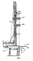
- Figure 1 is a side view of a typical drilling rig structure showing a V-door ramp in accordance with one embodiment of the present invention connected to the drilling rig structure.
- Figure 1 also shows two racking boards attached to and extending outwardly from the drilling rig's mast.
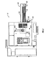
- Figure 2 is a top view of the drilling rig's floor showing the V-door ramp in accordance with one embodiment of the present invention connected to the drilling rig structure.
- FIG. 3 is a close-up top view of the V-door ramp showing the stationary section and the pivoting section of the V-door ramp in accordance with one embodiment of the present invention.
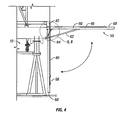
- FIG. 4 is a close-up side view of the V-door ramp showing the stationary section and the pivoting section of the V-door ramp in accordance with one embodiment of the present invention.
- Figure 5 is a detailed side view of the pivoting section of the V-door ramp according to one embodiment of the present invention showing the support cylinder connected between the drilling rig structure and the pivoting section of the V-door ramp in the extended position whereby the pivoting section of the V-door ramp is in the horizontal position.
- Figure 6 is a detailed side view of the pivoting section of the V-door ramp according to one embodiment of the present invention showing the support cylinder connected between the drilling rig structure and the pivoting section of the V-door ramp in the retracted position whereby the pivoting section of the V-door ramp is in the vertical position.
- V-door ramp 50 is shown connected to a drilling rig structure 10.
- Drilling rig structure 10 can be either a land based drilling rig or an offshore drilling rig.
- V-door ramp 50 is comprised of two sections - stationary section 55 and pivoting section 60.
- Stationary section 55 is supported in the horizontal position as shown in Figure 1 by support member 62 that is connected between V-door ramp 50 and rig structure 10.
- support member 62 that is connected between V-door ramp 50 and rig structure 10.
- a plurality of support members 62 may be necessary to support the combined weight of stationary section 55 and the drill pipe joints.
- V-door ramp 50 can be a "slanted" ramp that is connected on one end to rig structure 10 while the other end slants diagonally toward the ground (if used on a land based drilling rig) or toward a lower, pipe deck (if used on an offshore drilling rig).
- V-door ramp 50 is a horizontal ramp or a slanted ramp.
- Pivoting section 60 of V-door ramp 50 is shown in Figure 1 in both the horizontal position (solid lines) and in the vertical position (dashed lines). As discussed in more detail with reference to Figures 4 through 6 , pivoting section 60 is supported in both the horizontal and vertical positions by support cylinder 64. If V-door ramp 50 is a slanted ramp (as discussed in the preceding paragraph), pivoting section 60 will be sized such that it can pivot from the slanted position to the vertical position as required to achieve the objectives of the present invention.
- Figure 1 also shows two racking boards - 200 and 210 - attached to the mast 20 of the rig structure 10.
- Racking board 200 is used to store, or "rack", stands of drill pipe that consist of three joints of drill pipe connected together and, thus, measure approximately 90 feet in length.
- Racking board 210 is used to rack stands of drill pipe that consist of four joints of drill pipe connected together and, thus, measure approximately 120 feet in length.
- a lower racking board may be attached to the drilling rig mast to rack stands of drill pipe that consist of two joints of drill pipe connected together and, thus, measure approximately 60 feet in length.
- the size of the drill pipe stands to be made-up using the present invention will depend primarily on the size of the drilling rig's mast.
- FIG 2 is a top view of the rig floor of rig structure 10 showing V-door ramp 50 attached to rig structure 10.
- V-door ramp 50 consists of stationary section 55 and pivoting section 60.
- V-door ramp 50 is used to support the individual pipe joints 40 that are used to make-up the drill string during drilling operations.
- Figure 2 also shows positioning cylinder 68 within pivoting section 60 used for positioning pipe joint(s) 40 vertically at the proper height during the off-line make-up operation (as discussed in more detail with reference to Figures 3 through 6 ).
- Figure 2 shows off-line roughneck 100 mounted on an elevated platform 105 that is connected to rig structure 10 near V-door ramp 50.
- the borehole will be drilled using the main drilling equipment of rig structure 10 (as discussed previously). While the main drilling equipment drills the borehole, crew members can prepare for the connection of additional pipe joints to the drill string using the off-line make-up system of the present invention. As noted, 60-foot drill pipe stands, 90-foot drill pipe stands, or 120-foot drill pipe stands can be assembled using the off-line make-up system of the present invention. One of skill in the art will appreciate, however, that if the mast of a drilling rig increases in size, it is possible that even longer stands may be assembled using the off-line make-up system of the present invention.
- pivoting section 60 of V-door ramp 50 can be sized to hold either one or two joints of drill pipe.
- pivoting section 60 can be sized to hold one pipe joint 40.
- pivoting section 60 can be sized to hold two pipe joints 40.
- pivoting section 60 can be sized to hold three or even four pipe joints 40 depending on the size of the drill pipe stands to be assembled off-line.
- the holding means comprises a hinged bar that is attached to one side of pivoting section 60 such that the bar can be "swung” over the top of the pipe joints 40 into a latching mechanism on the opposite side of pivoting section 60.
- the holding means maintains the pipe joints 40 in the vertical position when pivoting section 60 is pivoted downwardly.
- the holding means can be either automatically “triggered” to close over the top of pipe joints 40 when they are rolled onto pivoting section 60, or it can be manually closed over the top of the pipe joints 40 by members of the drilling rig crew.
- pivoting section 60 is pivoted downwardly until the pipe joints 40 are in the vertical position.
- the holding means prevents the pipe joints 40 from falling out of pivoting section 60 when in the vertical position.
- Positioning cylinder 68 is used to raise or lower the pipe joints 40 to the proper position for connection to off-line roughneck 100.
- a third pipe joint 40 is lifted from the stationary section 55 of V-door ramp 50 and raised above the area around platform 105 and V-door ramp 50.
- the third pipe joint 40 is lifted from the stationary section 55 of V-door ramp 50 by connecting tool joint 42 of the third pipe joint 40 to an off-line drill pipe elevator.
- the off-line drill pipe elevator is then raised by either a winch located in mast 20 or located on the rig floor of rig structure 10, or by a bridge trolley (shown as 205 in Figure 1 ) mounted on an elevated platform attached to mast 20.
- Third pipe joint 40 is then positioned above the pipe joints 40 in pivoting section 60 (which is in the vertical position) that is closest to off-line roughneck 100.
- the third pipe joint 40 is then lowered via the off-line drill pipe elevator such that the lower end of the third pipe joint 40 engages one of the vertically held pipe joints 40.
- Off-line roughneck 100 is then moved forward toward pivoting section 60 until it reaches the engaged pipe joints 40.
- the upper tongs of off-line roughneck 100 "grab" the bottom portion of the third pipe joint (which is held in place by the off-line drill pipe elevator), while the lower tongs of off-line roughneck 100 "grab” the top portion of the engaged pipe joint 40 held in the vertical position within pivoting section 60.
- Off-line roughneck 100 is then used to apply the necessary rotation to the engaged pipe joints 40 for the initial make-up of the connection and to apply the necessary final make-up torque to the threaded connection.
- One of skill in the art will appreciate that numerous movable or "extendable" iron roughnecks exist that can be used for off-line roughneck 100 in the present invention, one such roughneck being National-Oilwell's IR30-80 Roughneck.
- off-line roughneck 100 After off-line roughneck 100 makes-up the connection, it is disengaged from the pipe joints 40, and the off-line drill pipe elevator is used to lift the connected pipe joints 40 above platform 105. The connected pipe joints 40 are then positioned above the remaining pipe joint 40 held in the vertical position within pivoting section 60. The lower end of the connected pipe joints 40 is then lowered via the off-line drill pipe elevator such that the lower end of the connected pipe joints 40 engages the remaining vertically held pipe joint 40. Off-line roughneck 100 is then moved forward toward pivoting section 60 until it reaches the engaged pipe joints 40.
- Off-line roughneck 100 is then used to apply the necessary rotation to the engaged pipe joints 40 for the initial make-up of the connection and to apply the necessary final make-up torque to the threaded connection.
- off-line roughneck 100 releases the connected joints of drill pipe, and the stand of drill pipe - now measuring 90 feet in length - is moved into position for storage in racking board 200 (shown in Figure 1 ) through use of the off-line drill pipe elevator.
- a 60-foot drill pipe stand can be assembled.
- a 60-foot stand only one pipe joint 40 is rolled onto pivoting section 60 of V-door ramp 50 and pivoted downwardly until it is in a vertical position.
- the pipe joint 40 held in the vertical position in pivoting section 60 can then be attached to a second pipe joint 40 lifted directly from the stationary section 55 of V-door ramp 50 in the manner described above.
- pivoting section 60 of V-door ramp 50 can be designed to hold only one pipe joint 40.
- a fourth pipe joint 40 can be attached to the 90-foot drill pipe stand to form a 120-foot drill pipe stand.
- a fourth pipe joint 40 is rolled onto pivoting section 60 of V-door ramp 50 and pivoted downwardly until it is in the vertical position.
- the pipe joint 40 held in the vertical position in pivoting section 60 can then be attached to the three pipe joint section that has been previously made up in the manner described above with respect to the 90-foot drill pipe stand.
- the 120-foot drill pipe stand can than be moved into position for storage in racking board 210 (shown in Figure 1 ) through use of the off line drill pipe elevator.
- pivoting section 60 is connected to rig structure 10 via pin connection 52.
- Pin connection 52 allows pivoting section 60 to rotate downwardly while remaining connected to rig structure 10.
- Similar pin connections 65 and 66 are used to connect support cylinder 64 to pivoting section 60 and rig structure 10 respectively.
- pivoting section 60 is shown in the horizontal position. In this position, support cylinder 64 is in the fully extended position. To “pivot" pivoting section 60 downwardly, support cylinder 64 is slowly retracted. As support cylinder 64 is retracted, pivoting section 60 rotates about pin connector 52 and begins to lower toward the vertical position shown in Figure 6 . As support cylinder 64 continues to retract, support cylinder 64 is allowed to rotate about its connection points to the pivoting section 60 (via pin connection 65) and the rig structure 10 (via pin connection 66) such that pin connection 65 forces support cylinder 64 toward rig structure 10. In the preferred embodiment, support cylinder 64 is specifically sized to be fully retracted (or “bottomed out") when pivoting section 60 is in the vertical position, as shown in Figure 6 .
- the present invention significantly reduces the amount of pipe handling required to assemble drill pipe stands off-line. This reduction in pipe handling allows for a more efficient and safer off-line make-up operation. Further, it will be appreciated that the pivoting V-door ramp section of the present invention alleviates the need for the "off line holes" used in the prior art, thereby removing another safety concern found in the prior art.
Claims (49)
- Système destiné à la réparation hors ligne de joints de tubulaires de champs de pétrole sur une structure d'appareil de forage comprenant :une rampe de porte en V reliée à la structure d'appareil de forage, la rampe de porte en V ayant une section immobile et une section pivotante, dans lequel la section pivotante est apte à pivoter entre une première position et une deuxième position ;au moins un cylindre de support ayant une première extrémité et une deuxième extrémité, dans lequel la première extrémité est reliée de manière à pouvoir pivoter à la structure d'appareil de forage et la deuxième extrémité est reliée de manière à pouvoir pivoter à la section pivotante de la rampe de porte en V ;caractérisé en ce que la structure comprend en outre :un moyen de maintien pour fixer au moins un joint de tubulaire dans la section pivotante de la rampe de porte en V lorsque la section pivotante se trouve à la deuxième position ; etun cylindre de positionnement relié à la section pivotante de la rampe de porte en V, dans lequel le cylindre de positionnement est apte à positionner l'au moins un joint de tubulaire dans la section pivotante.
- Système selon la revendication 1, dans lequel la section pivotante de la rampe de porte en V est en ligne avec la section immobile de la rampe de porte en V à la première position.
- Système selon la revendication 2, dans lequel l'au moins un cylindre de support se trouve à une position étendue lorsque la section pivotante de la rampe de porte en V se trouve à la première position.
- Système selon la revendication 1, dans lequel la section pivotante de la rampe de porte en V se trouve à une position sensiblement verticale à la deuxième position.
- Système selon la revendication 4, dans lequel l'au moins un cylindre de support se trouve à une position entièrement rétractée lorsque la section pivotante de la rampe de porte en V se trouve à la deuxième position.
- Système selon la revendication 1, dans lequel le moyen de maintien comprend une barre reliée en charnière à la section pivotante de la rampe de porte en V et un mécanisme de verrou.
- Système selon la revendication 6, dans lequel la barre du moyen de maintien est déplacée à partir d'une première position à laquelle la section pivotante de la rampe de porte en V est en mesure de recevoir l'au moins un joint de tubulaire jusqu'à une deuxième position à laquelle la barre se met en prise avec le mécanisme de verrou pour fixer l'au moins un joint de tubulaire dans la section pivotante de la rampe de porte en V lorsque la section pivotante se trouve à la deuxième position.
- Système selon la revendication 1, dans lequel la première extrémité de l'au moins un cylindre de support est reliée de manière à pouvoir pivoter à la structure d'appareil de forage par une liaison de broche.
- Système selon la revendication 1, dans lequel la deuxième extrémité de l'au moins un cylindre de support est reliée de manière à pouvoir pivoter à la section pivotante de la rampe de porte en V par une liaison de broche.
- Système selon la revendication 1, comprenant en outre une plate-forme élevée sur laquelle est monté un foreur en fer.
- Système selon la revendication 1, comprenant en outre un élévateur de tubulaire.
- Système selon la revendication 11, dans lequel l'élévateur de tubulaire est monté ou descendu par un treuil.
- Système selon la revendication 11, dans lequel l'élévateur de tubulaire est monté ou descendu par un chariot à portique relié à une plate-forme élevée qui est reliée à un mât de la structure d'appareil de forage.
- Système selon la revendication 1, comprenant en outre au moins une passerelle d'accrochage reliée au mât de la structure d'appareil de forage, l'au moins une passerelle d'accrochage étant apte à stocker hors ligne un banc de tubulaires se composant de plusieurs tubulaires joints les uns aux autres.
- Système selon la revendication 1, comprenant en outre au moins un organe de support s'étendant à partir de la structure d'appareil de forage jusqu'à la section immobile de la rampe de porte en V.
- Système selon la revendication 1, dans lequel la section immobile supporte au moins un joint de tubulaire et la section pivotante supporte au moins un joint de tubulaire et peut pivoter par rapport à la structure d'appareil de forage ; et dans lequel le moyen de maintien comprend :un mécanisme de maintien comprenant une barre reliée en charnière à la section pivotante de la rampe de porte en V et un mécanisme de verrou, dans lequel la barre et le mécanisme de verrou coopèrent pour fixer l'au moins un joint de tubulaire dans la section pivotante ;le système comprenant en outre :un élévateur de tubulaire pour monter ou descendre au moins un joint de tubulaire ;un foreur en fer mobile, dans lequel le foreur en fer mobile peut être étendu de manière à prendre l'un de l'au moins un joint de tubulaire supporté par l'élévateur de tubulaire et l'un de l'au moins un joint de tubulaire dans la section pivotante de la rampe de porte en V ; etau moins une passerelle d'accrochage, dans lequel l'au moins une passerelle d'accrochage est reliée à un mât de la structure d'appareil de forage.
- Système selon la revendication 16, dans lequel la section pivotante de la rampe de porte en V est en ligne avec la section immobile de la rampe de porte en V lorsque l'au moins un cylindre de support se trouve à une position étendue.
- Système selon la revendication 16, dans lequel la section pivotante de la rampe de porte en V se trouve à une position sensiblement verticale lorsque l'au moins un cylindre de support se trouve à une position entièrement rétractée.
- Système selon la revendication 16, dans lequel la barre du mécanisme de maintien est déplacée à partir d'une première position à laquelle la section pivotante de la rampe de porte en V est en mesure de recevoir l'au moins un joint de tubulaire jusqu'à une deuxième position à laquelle la barre se met en prise avec le mécanisme de verrou pour fixer l'au moins un joint de tubulaire dans la section pivotante de la rampe de porte en V lorsque la section pivotante se trouve à la position sensiblement verticale.
- Système selon la revendication 16, dans lequel la première extrémité de l'au moins un cylindre de support est reliée de manière à pouvoir pivoter à la structure d'appareil de forage par une liaison de broche.
- Système selon la revendication 16, dans lequel la deuxième extrémité de l'au moins un cylindre de support est reliée de manière à pouvoir pivoter à la section pivotante de la rampe de porte en V par une liaison de broche.
- Système selon la revendication 16, dans lequel le foreur en fer mobile est monté sur une plate-forme élevée.
- Système selon la revendication 16, dans lequel l'élévateur de tubulaire est monté ou descendu par un treuil.
- Système selon la revendication 16, dans lequel l'élévateur de tubulaire est monté ou descendu par un chariot à portique relié à une plate-forme élevée qui est reliée au mât de la structure d'appareil de forage.
- Système selon la revendication 16, dans lequel l'au moins une passerelle d'accrochage est apte à stocker hors ligne un banc à tubulaire se composant de plusieurs tubulaires joints les uns aux autres.
- Système selon la revendication 16, comprenant en outre au moins un organe de support s'étendant à partir de la structure d'appareil de forage jusqu'à la section immobile de la rampe de porte en V.
- Procédé destiné à la réparation hors ligne de tubulaires de champs de pétrole sur une structure d'appareil de forage comprenant :la fourniture d'une rampe de porte en V reliée à la structure d'appareil de forage, la rampe de porte en V ayant une section pivotante et une section immobile ;le support d'au moins deux joints de tubulaires sur la section immobile de la rampe de porte en V ;caractérisé en ce que le procédé comprend en outre :le déplacement d'au moins l'un des au moins deux joints de tubulaires vers la section pivotante de la rampe de porte en V ;la fixation de l'au moins un joint de tubulaire sur la section pivotante de la rampe de porte en V ;le pivotement de la section pivotante de la rampe de porte en V à partir d'une première position jusqu'à une deuxième position ;le soulèvement de l'un des au moins deux joints de tubulaires supportés sur la section immobile de la rampe de porte en V de sorte que le joint de tubulaire soit positionné au-dessus de la section pivotante de la rampe de porte en V ; etla liaison du joint de tubulaire fixé sur la section pivotante de la rampe de porte en V au joint de tubulaire soulevé au-dessus de la section pivotante de la rampe de porte en V pour créer un banc à tubulaire.
- Procédé selon la revendication 27, comprenant en outre le déplacement du banc à tubulaire vers une passerelle d'accrochage apte à stocker le banc à tubulaire, dans lequel la passerelle d'accrochage est reliée à un mât de la structure d'appareil de forage.
- Procédé selon la revendication 27, comprenant en outre l'extension ou la rétraction d'un cylindre de positionnement relié à la section pivotante de la rampe de porte en V pour positionner l'au moins un joint de tubulaire à l'intérieur de la section pivotante.
- Procédé selon la revendication 27, dans lequel la section pivotante de la rampe de porte en V est pivotée jusqu'à la deuxième position en rétractant un cylindre de support ayant une première extrémité reliée à la structure d'appareil de forage et une deuxième extrémité reliée à la section pivotante.
- Procédé selon la revendication 27, dans lequel le joint de tubulaire est soulevé à partir de la section immobile de la rampe de porte en V jusqu'à une position au-dessus de la section pivotante de la rampe de porte en V en reliant un élévateur de tubulaire au joint de tubulaire et en montant l'élévateur de tubulaire.
- Procédé selon la revendication 31, dans lequel l'élévateur de tubulaire est monté ou descendu par un treuil.
- Procédé selon la revendication 31, dans lequel l'élévateur de tubulaire est monté ou descendu par un chariot à portique relié à une plate-forme élevée qui est reliée à un mât de la structure d'appareil de forage.
- Procédé selon la revendication 31, comprenant en outre la mise en prise de l'un de l'au moins un joint de tubulaire fixé dans la section pivotante de la rampe de porte en V et la mise en prise du joint de tubulaire soulevé au-dessus de la section pivotante avec un foreur en fer.
- Procédé selon la revendication 34, comprenant en outre l'utilisation du foreur en fer pour réparer la liaison entre les joints de tubulaires mis en prise par le foreur en fer.
- Procédé selon la revendication 27, dans lequel le procédé comprend :le support d'une pluralité de joints de tubulaires sur la section immobile de la rampe de porte en V ;le déplacement d'au moins deux de la pluralité de joints de tubulaires vers la section pivotante de la rampe de porte en V ;la fixation des au moins deux joints de tubulaires sur la section pivotante de la rampe de porte en V ;le pivotement de la section pivotante de la rampe de porte en V à partir d'une première position jusqu'à une deuxième position, dans lequel la section pivotante se trouve à une position sensiblement verticale à la deuxième position ;le soulèvement de l'un de la pluralité de joints de tubulaires supportés sur la section immobile de la rampe de porte en V de sorte que le joint de tubulaire soit à une position sensiblement verticale au-dessus de la section pivotante de la rampe de porte en V ;la liaison de l'un des au moins deux joints de tubulaires fixés sur la section pivotante de la rampe de porte en V au joint de tubulaire soulevé au-dessus de la section pivotante de la rampe de porte en V pour créer un banc à deux tubulaires ;le soulèvement du banc à deux tubulaires de sorte que le banc à deux tubulaires se trouve à une position sensiblement verticale au-dessus de la section pivotante de la rampe de porte en V ;la liaison de l'un des au moins deux joints de tubulaires fixés sur la section pivotante de la rampe de porte en V au banc à deux tubulaires soulevé au-dessus de la section pivotante pour créer un banc à trois tubulaires.
- Procédé selon la revendication 36, comprenant en outre le déplacement du banc à trois tubulaires vers une passerelle d'accrochage apte à stocker le banc à tubulaire, dans lequel la passerelle d'accrochage est reliée à un mât de la structure d'appareil de forage.
- Procédé selon la revendication 36, comprenant en outre l'extension ou la rétraction d'un cylindre de positionnement relié à la section pivotante de la rampe de porte en V pour positionner les joints de tubulaires à l'intérieur de la section pivotante.
- Procédé selon la revendication 36, dans lequel la section pivotante de la rampe de porte en V est pivotée en rétractant un cylindre de support ayant une première extrémité reliée à la structure d'appareil de forage et une deuxième extrémité reliée à la section pivotante.
- Procédé selon la revendication 36, dans lequel le joint de tubulaire est soulevé à partir de la section immobile de la rampe de porte en V jusqu'à une position au-dessus de la section pivotante de la rampe de porte en V en reliant le joint de tubulaire à un élévateur de tubulaire et en montant l'élévateur de tubulaire.
- Procédé selon la revendication 36, dans lequel le banc à deux tubulaires est monté à une position au-dessus de la section pivotante de la rampe de porte en V en montant l'élévateur de tubulaire.
- Procédé selon la revendication 41, dans lequel l'élévateur de tubulaire est monté ou descendu par un treuil.
- Procédé selon la revendication 41, dans lequel l'élévateur de tubulaire est monté ou descendu par un chariot à portique relié à une plate-forme élevée qui est reliée à un mât de la structure d'appareil de forage.
- Procédé selon la revendication 36, comprenant en outre la mise en prise de l'un des au moins deux joints de tubulaires fixés dans la section pivotante de la rampe de porte en V et la mise en prise du joint de tubulaire soulevé au-dessus de la section pivotante avec un foreur en fer.
- Procédé selon la revendication 44, comprenant en outre l'utilisation du foreur en fer pour réparer la liaison entre les joints de tubulaires mis en prise par le foreur en fer pour créer le banc à deux tubulaires.
- Procédé selon la revendication 45, comprenant en outre la mise en prise de l'un des au moins deux joints de tubulaires fixés dans la section pivotante de la rampe de porte en V et l'un des joints de tubulaires comprenant le banc à deux tubulaires avec un foreur en fer.
- Procédé selon la revendication 46, comprenant en outre l'utilisation du foreur en fer pour réparer la liaison entre les joints de tubulaires mis en prise par le foreur en fer pour créer le banc à trois tubulaires.
- Procédé selon la revendication 27, comprenant en outre :le support d'au moins un joint de tubulaire sur la section pivotante de la rampe de porte en V.
- Procédé destiné à manipuler des joints de tubulaires de champs de pétrole hors ligne comprenant :la fourniture d'une rampe de porte en V reliée à la structure d'appareil de forage, la rampe de porte en V ayant une section pivotante et une section immobile ;le support d'au moins deux joints de tubulaires sur la section immobile de la rampe de porte en V ;le support d'au moins un joint de tubulaire sur la section pivotante de la rampe de porte en V ;la fixation de l'au moins un joint de tubulaire sur la section pivotante de la rampe de porte en V ;le pivotement de la section pivotante de la rampe de porte en V à partir d'une première position jusqu'à une deuxième position.
Applications Claiming Priority (2)
| Application Number | Priority Date | Filing Date | Title |
|---|---|---|---|
| US62004904P | 2004-10-19 | 2004-10-19 | |
| PCT/US2005/037353 WO2006044848A2 (fr) | 2004-10-19 | 2005-10-18 | Dispositif pivotant de manipulation de tiges de forage utilise dans la reparation hors ligne de joints de tiges de forage |
Publications (3)
| Publication Number | Publication Date |
|---|---|
| EP1809855A2 EP1809855A2 (fr) | 2007-07-25 |
| EP1809855A4 EP1809855A4 (fr) | 2012-09-26 |
| EP1809855B1 true EP1809855B1 (fr) | 2013-11-20 |
Family
ID=38171503
Family Applications (1)
| Application Number | Title | Priority Date | Filing Date |
|---|---|---|---|
| EP05808892.3A Active EP1809855B1 (fr) | 2004-10-19 | 2005-10-18 | Dispositif pivotant de manipulation de tiges de forage utilise dans la reparation hors ligne de joints de tiges de forage |
Country Status (2)
| Country | Link |
|---|---|
| EP (1) | EP1809855B1 (fr) |
| DK (1) | DK1809855T3 (fr) |
Family Cites Families (1)
| Publication number | Priority date | Publication date | Assignee | Title |
|---|---|---|---|---|
| US7431550B2 (en) * | 2002-10-04 | 2008-10-07 | Technologies Alliance | Pipe handling apparatus for pick-up and lay-down machine |
-
2005
- 2005-10-18 DK DK05808892.3T patent/DK1809855T3/en active
- 2005-10-18 EP EP05808892.3A patent/EP1809855B1/fr active Active
Also Published As
| Publication number | Publication date |
|---|---|
| EP1809855A2 (fr) | 2007-07-25 |
| DK1809855T3 (en) | 2014-02-17 |
| EP1809855A4 (fr) | 2012-09-26 |
Similar Documents
| Publication | Publication Date | Title |
|---|---|---|
| CA2584323C (fr) | Dispositif pivotant de manipulation de tiges de forage utilise dans la reparation hors ligne de joints de tiges de forage | |
| US11661800B1 (en) | Support apparatus for supporting down hole rotary tools | |
| US7527100B2 (en) | Method and apparatus for cutting and removal of pipe from wells | |
| US7249639B2 (en) | Automated arm for positioning of drilling tools such as an iron roughneck | |
| US7353880B2 (en) | Method and apparatus for connecting tubulars using a top drive | |
| US8371790B2 (en) | Derrickless tubular servicing system and method | |
| RU2435929C2 (ru) | Способ и устройство для проведения операций в подземных буровых скважинах | |
| US9217297B2 (en) | Method and support apparatus for supporting down hole rotary tools | |
| US20090101332A1 (en) | Method and apparatus for drilling with casing | |
| US20070251700A1 (en) | Tubular running system | |
| WO2011135541A2 (fr) | Système modulaire à plusieurs trains d'exploitation destiné à des opérations sous-marines d'intervention et d'abandon | |
| US20070240884A1 (en) | Pivoting pipe handler for off-line make up of drill pipe joints | |
| WO2016196808A1 (fr) | Système et procédé de guidage de tige de forage | |
| US20170314345A1 (en) | Assemblies and methods for inserting and removing tubulars from a wellbore | |
| US11118414B2 (en) | Tubular delivery arm for a drilling rig | |
| EP1809855B1 (fr) | Dispositif pivotant de manipulation de tiges de forage utilise dans la reparation hors ligne de joints de tiges de forage | |
| WO2020210795A1 (fr) | Procédé d'assemblage d'équipement de puits à l'aide d'une passerelle et d'une grue combinées | |
| CA2714327C (fr) | Procede et dispositif de forage avec cuvelage | |
| CA2517993C (fr) | Procede et dispositif de forage avec cuvelage | |
| CA2877530C (fr) | Appareil de forage mobile et procede |
Legal Events
| Date | Code | Title | Description |
|---|---|---|---|
| PUAI | Public reference made under article 153(3) epc to a published international application that has entered the european phase |
Free format text: ORIGINAL CODE: 0009012 |
|
| 17P | Request for examination filed |
Effective date: 20070515 |
|
| AK | Designated contracting states |
Kind code of ref document: A2 Designated state(s): AT BE BG CH CY CZ DE DK EE ES FI FR GB GR HU IE IS IT LI LT LU LV MC NL PL PT RO SE SI SK TR |
|
| AX | Request for extension of the european patent |
Extension state: AL BA HR MK YU |
|
| RIC1 | Information provided on ipc code assigned before grant |
Ipc: E21B 19/00 20060101AFI20070815BHEP |
|
| DAX | Request for extension of the european patent (deleted) | ||
| A4 | Supplementary search report drawn up and despatched |
Effective date: 20120828 |
|
| RIC1 | Information provided on ipc code assigned before grant |
Ipc: E21B 19/00 20060101AFI20120822BHEP Ipc: E21B 19/18 20060101ALI20120822BHEP |
|
| REG | Reference to a national code |
Ref country code: DE Ref legal event code: R079 Ref document number: 602005041945 Country of ref document: DE Free format text: PREVIOUS MAIN CLASS: E21B0019180000 Ipc: E21B0019000000 |
|
| GRAP | Despatch of communication of intention to grant a patent |
Free format text: ORIGINAL CODE: EPIDOSNIGR1 |
|
| RIC1 | Information provided on ipc code assigned before grant |
Ipc: E21B 19/18 20060101ALI20130419BHEP Ipc: E21B 19/00 20060101AFI20130419BHEP |
|
| INTG | Intention to grant announced |
Effective date: 20130524 |
|
| GRAS | Grant fee paid |
Free format text: ORIGINAL CODE: EPIDOSNIGR3 |
|
| GRAA | (expected) grant |
Free format text: ORIGINAL CODE: 0009210 |
|
| RAP1 | Party data changed (applicant data changed or rights of an application transferred) |
Owner name: NATIONAL OILWELL VARCO, L.P. |
|
| AK | Designated contracting states |
Kind code of ref document: B1 Designated state(s): AT BE BG CH CY CZ DE DK EE ES FI FR GB GR HU IE IS IT LI LT LU LV MC NL PL PT RO SE SI SK TR |
|
| REG | Reference to a national code |
Ref country code: GB Ref legal event code: FG4D |
|
| REG | Reference to a national code |
Ref country code: CH Ref legal event code: EP |
|
| REG | Reference to a national code |
Ref country code: AT Ref legal event code: REF Ref document number: 641774 Country of ref document: AT Kind code of ref document: T Effective date: 20131215 |
|
| REG | Reference to a national code |
Ref country code: IE Ref legal event code: FG4D |
|
| REG | Reference to a national code |
Ref country code: DE Ref legal event code: R096 Ref document number: 602005041945 Country of ref document: DE Effective date: 20140109 |
|
| REG | Reference to a national code |
Ref country code: NL Ref legal event code: T3 |
|
| REG | Reference to a national code |
Ref country code: DK Ref legal event code: T3 Effective date: 20140213 |
|
| REG | Reference to a national code |
Ref country code: AT Ref legal event code: MK05 Ref document number: 641774 Country of ref document: AT Kind code of ref document: T Effective date: 20131120 |
|
| REG | Reference to a national code |
Ref country code: LT Ref legal event code: MG4D |
|
| PG25 | Lapsed in a contracting state [announced via postgrant information from national office to epo] |
Ref country code: SE Free format text: LAPSE BECAUSE OF FAILURE TO SUBMIT A TRANSLATION OF THE DESCRIPTION OR TO PAY THE FEE WITHIN THE PRESCRIBED TIME-LIMIT Effective date: 20131120 Ref country code: IS Free format text: LAPSE BECAUSE OF FAILURE TO SUBMIT A TRANSLATION OF THE DESCRIPTION OR TO PAY THE FEE WITHIN THE PRESCRIBED TIME-LIMIT Effective date: 20140320 Ref country code: FI Free format text: LAPSE BECAUSE OF FAILURE TO SUBMIT A TRANSLATION OF THE DESCRIPTION OR TO PAY THE FEE WITHIN THE PRESCRIBED TIME-LIMIT Effective date: 20131120 Ref country code: LT Free format text: LAPSE BECAUSE OF FAILURE TO SUBMIT A TRANSLATION OF THE DESCRIPTION OR TO PAY THE FEE WITHIN THE PRESCRIBED TIME-LIMIT Effective date: 20131120 |
|
| PG25 | Lapsed in a contracting state [announced via postgrant information from national office to epo] |
Ref country code: LV Free format text: LAPSE BECAUSE OF FAILURE TO SUBMIT A TRANSLATION OF THE DESCRIPTION OR TO PAY THE FEE WITHIN THE PRESCRIBED TIME-LIMIT Effective date: 20131120 Ref country code: ES Free format text: LAPSE BECAUSE OF FAILURE TO SUBMIT A TRANSLATION OF THE DESCRIPTION OR TO PAY THE FEE WITHIN THE PRESCRIBED TIME-LIMIT Effective date: 20131120 Ref country code: BE Free format text: LAPSE BECAUSE OF FAILURE TO SUBMIT A TRANSLATION OF THE DESCRIPTION OR TO PAY THE FEE WITHIN THE PRESCRIBED TIME-LIMIT Effective date: 20131120 Ref country code: AT Free format text: LAPSE BECAUSE OF FAILURE TO SUBMIT A TRANSLATION OF THE DESCRIPTION OR TO PAY THE FEE WITHIN THE PRESCRIBED TIME-LIMIT Effective date: 20131120 |
|
| PG25 | Lapsed in a contracting state [announced via postgrant information from national office to epo] |
Ref country code: EE Free format text: LAPSE BECAUSE OF FAILURE TO SUBMIT A TRANSLATION OF THE DESCRIPTION OR TO PAY THE FEE WITHIN THE PRESCRIBED TIME-LIMIT Effective date: 20131120 |
|
| REG | Reference to a national code |
Ref country code: DE Ref legal event code: R097 Ref document number: 602005041945 Country of ref document: DE |
|
| PG25 | Lapsed in a contracting state [announced via postgrant information from national office to epo] |
Ref country code: SK Free format text: LAPSE BECAUSE OF FAILURE TO SUBMIT A TRANSLATION OF THE DESCRIPTION OR TO PAY THE FEE WITHIN THE PRESCRIBED TIME-LIMIT Effective date: 20131120 Ref country code: PL Free format text: LAPSE BECAUSE OF FAILURE TO SUBMIT A TRANSLATION OF THE DESCRIPTION OR TO PAY THE FEE WITHIN THE PRESCRIBED TIME-LIMIT Effective date: 20131120 Ref country code: RO Free format text: LAPSE BECAUSE OF FAILURE TO SUBMIT A TRANSLATION OF THE DESCRIPTION OR TO PAY THE FEE WITHIN THE PRESCRIBED TIME-LIMIT Effective date: 20131120 Ref country code: CZ Free format text: LAPSE BECAUSE OF FAILURE TO SUBMIT A TRANSLATION OF THE DESCRIPTION OR TO PAY THE FEE WITHIN THE PRESCRIBED TIME-LIMIT Effective date: 20131120 |
|
| PLBE | No opposition filed within time limit |
Free format text: ORIGINAL CODE: 0009261 |
|
| STAA | Information on the status of an ep patent application or granted ep patent |
Free format text: STATUS: NO OPPOSITION FILED WITHIN TIME LIMIT |
|
| 26N | No opposition filed |
Effective date: 20140821 |
|
| REG | Reference to a national code |
Ref country code: DE Ref legal event code: R097 Ref document number: 602005041945 Country of ref document: DE Effective date: 20140821 |
|
| PG25 | Lapsed in a contracting state [announced via postgrant information from national office to epo] |
Ref country code: SI Free format text: LAPSE BECAUSE OF FAILURE TO SUBMIT A TRANSLATION OF THE DESCRIPTION OR TO PAY THE FEE WITHIN THE PRESCRIBED TIME-LIMIT Effective date: 20131120 |
|
| REG | Reference to a national code |
Ref country code: DE Ref legal event code: R119 Ref document number: 602005041945 Country of ref document: DE |
|
| PG25 | Lapsed in a contracting state [announced via postgrant information from national office to epo] |
Ref country code: LU Free format text: LAPSE BECAUSE OF FAILURE TO SUBMIT A TRANSLATION OF THE DESCRIPTION OR TO PAY THE FEE WITHIN THE PRESCRIBED TIME-LIMIT Effective date: 20141018 Ref country code: MC Free format text: LAPSE BECAUSE OF FAILURE TO SUBMIT A TRANSLATION OF THE DESCRIPTION OR TO PAY THE FEE WITHIN THE PRESCRIBED TIME-LIMIT Effective date: 20131120 |
|
| REG | Reference to a national code |
Ref country code: CH Ref legal event code: PL |
|
| REG | Reference to a national code |
Ref country code: IE Ref legal event code: MM4A |
|
| PG25 | Lapsed in a contracting state [announced via postgrant information from national office to epo] |
Ref country code: DE Free format text: LAPSE BECAUSE OF NON-PAYMENT OF DUE FEES Effective date: 20150501 Ref country code: CH Free format text: LAPSE BECAUSE OF NON-PAYMENT OF DUE FEES Effective date: 20141031 Ref country code: LI Free format text: LAPSE BECAUSE OF NON-PAYMENT OF DUE FEES Effective date: 20141031 |
|
| REG | Reference to a national code |
Ref country code: FR Ref legal event code: ST Effective date: 20150630 |
|
| PG25 | Lapsed in a contracting state [announced via postgrant information from national office to epo] |
Ref country code: IT Free format text: LAPSE BECAUSE OF FAILURE TO SUBMIT A TRANSLATION OF THE DESCRIPTION OR TO PAY THE FEE WITHIN THE PRESCRIBED TIME-LIMIT Effective date: 20131120 Ref country code: FR Free format text: LAPSE BECAUSE OF NON-PAYMENT OF DUE FEES Effective date: 20141031 |
|
| PG25 | Lapsed in a contracting state [announced via postgrant information from national office to epo] |
Ref country code: IE Free format text: LAPSE BECAUSE OF NON-PAYMENT OF DUE FEES Effective date: 20141018 |
|
| PG25 | Lapsed in a contracting state [announced via postgrant information from national office to epo] |
Ref country code: BG Free format text: LAPSE BECAUSE OF FAILURE TO SUBMIT A TRANSLATION OF THE DESCRIPTION OR TO PAY THE FEE WITHIN THE PRESCRIBED TIME-LIMIT Effective date: 20131120 |
|
| PG25 | Lapsed in a contracting state [announced via postgrant information from national office to epo] |
Ref country code: CY Free format text: LAPSE BECAUSE OF FAILURE TO SUBMIT A TRANSLATION OF THE DESCRIPTION OR TO PAY THE FEE WITHIN THE PRESCRIBED TIME-LIMIT Effective date: 20131120 Ref country code: GR Free format text: LAPSE BECAUSE OF FAILURE TO SUBMIT A TRANSLATION OF THE DESCRIPTION OR TO PAY THE FEE WITHIN THE PRESCRIBED TIME-LIMIT Effective date: 20140221 Ref country code: PT Free format text: LAPSE BECAUSE OF FAILURE TO SUBMIT A TRANSLATION OF THE DESCRIPTION OR TO PAY THE FEE WITHIN THE PRESCRIBED TIME-LIMIT Effective date: 20131120 |
|
| PG25 | Lapsed in a contracting state [announced via postgrant information from national office to epo] |
Ref country code: TR Free format text: LAPSE BECAUSE OF FAILURE TO SUBMIT A TRANSLATION OF THE DESCRIPTION OR TO PAY THE FEE WITHIN THE PRESCRIBED TIME-LIMIT Effective date: 20131120 Ref country code: HU Free format text: LAPSE BECAUSE OF FAILURE TO SUBMIT A TRANSLATION OF THE DESCRIPTION OR TO PAY THE FEE WITHIN THE PRESCRIBED TIME-LIMIT; INVALID AB INITIO Effective date: 20051018 |
|
| PGFP | Annual fee paid to national office [announced via postgrant information from national office to epo] |
Ref country code: NL Payment date: 20201015 Year of fee payment: 16 |
|
| PGFP | Annual fee paid to national office [announced via postgrant information from national office to epo] |
Ref country code: DK Payment date: 20201012 Year of fee payment: 16 |
|
| REG | Reference to a national code |
Ref country code: DK Ref legal event code: EBP Effective date: 20211031 |
|
| REG | Reference to a national code |
Ref country code: NL Ref legal event code: MM Effective date: 20211101 |
|
| PG25 | Lapsed in a contracting state [announced via postgrant information from national office to epo] |
Ref country code: NL Free format text: LAPSE BECAUSE OF NON-PAYMENT OF DUE FEES Effective date: 20211101 |
|
| PG25 | Lapsed in a contracting state [announced via postgrant information from national office to epo] |
Ref country code: DK Free format text: LAPSE BECAUSE OF NON-PAYMENT OF DUE FEES Effective date: 20211031 |
|
| PGFP | Annual fee paid to national office [announced via postgrant information from national office to epo] |
Ref country code: GB Payment date: 20230831 Year of fee payment: 19 |