EP1809488B1 - Markierungsvorrichtung - Google Patents
Markierungsvorrichtung Download PDFInfo
- Publication number
- EP1809488B1 EP1809488B1 EP05805566.6A EP05805566A EP1809488B1 EP 1809488 B1 EP1809488 B1 EP 1809488B1 EP 05805566 A EP05805566 A EP 05805566A EP 1809488 B1 EP1809488 B1 EP 1809488B1
- Authority
- EP
- European Patent Office
- Prior art keywords
- marking
- rotation
- implement
- marked
- cradle
- Prior art date
- Legal status (The legal status is an assumption and is not a legal conclusion. Google has not performed a legal analysis and makes no representation as to the accuracy of the status listed.)
- Not-in-force
Links
Images


Classifications
-
- B—PERFORMING OPERATIONS; TRANSPORTING
- B44—DECORATIVE ARTS
- B44B—MACHINES, APPARATUS OR TOOLS FOR ARTISTIC WORK, e.g. FOR SCULPTURING, GUILLOCHING, CARVING, BRANDING, INLAYING
- B44B3/00—Artist's machines or apparatus equipped with tools or work holders moving or able to be controlled substantially two- dimensionally for carving, engraving, or guilloching shallow ornamenting or markings
- B44B3/06—Accessories, e.g. tool or work holders
- B44B3/063—Tool holders
-
- B—PERFORMING OPERATIONS; TRANSPORTING
- B23—MACHINE TOOLS; METAL-WORKING NOT OTHERWISE PROVIDED FOR
- B23Q—DETAILS, COMPONENTS, OR ACCESSORIES FOR MACHINE TOOLS, e.g. ARRANGEMENTS FOR COPYING OR CONTROLLING; MACHINE TOOLS IN GENERAL CHARACTERISED BY THE CONSTRUCTION OF PARTICULAR DETAILS OR COMPONENTS; COMBINATIONS OR ASSOCIATIONS OF METAL-WORKING MACHINES, NOT DIRECTED TO A PARTICULAR RESULT
- B23Q1/00—Members which are comprised in the general build-up of a form of machine, particularly relatively large fixed members
- B23Q1/25—Movable or adjustable work or tool supports
- B23Q1/44—Movable or adjustable work or tool supports using particular mechanisms
-
- Y—GENERAL TAGGING OF NEW TECHNOLOGICAL DEVELOPMENTS; GENERAL TAGGING OF CROSS-SECTIONAL TECHNOLOGIES SPANNING OVER SEVERAL SECTIONS OF THE IPC; TECHNICAL SUBJECTS COVERED BY FORMER USPC CROSS-REFERENCE ART COLLECTIONS [XRACs] AND DIGESTS
- Y10—TECHNICAL SUBJECTS COVERED BY FORMER USPC
- Y10T—TECHNICAL SUBJECTS COVERED BY FORMER US CLASSIFICATION
- Y10T409/00—Gear cutting, milling, or planing
- Y10T409/30—Milling
- Y10T409/30784—Milling including means to adustably position cutter
- Y10T409/307952—Linear adjustment
- Y10T409/308232—Linear adjustment and angular adjustment
Definitions
- the present invention relates to the technical field of devices for ensuring the marking of the surface of an object, by deformation of the latter in particular.
- the marking device is characterized in that it comprises means for compensating, at least partially, the influence of rotation on the distance between the marking member and the marking point on the surface. to score.
- compensation means means that automatically compensate for the influence of rotation on the distance between the marking member and the marking point on the surface to be marked.
- the compensation means are slaved to the rotation of the organ of marking, so as to compensate, automatically, the influence of rotation.
- the marking points, made by the marking member all have good quality anywhere in the marking window.
- the compensation can be performed more or less completely.
- the compensation means are adapted to maintain, at a constant value, the distance measured perpendicularly to the marking surface, between the marking member and the marked surface.
- the compensation means are adapted to maintain, at a constant value, the distance between the marking and the marking point on the surface to be marked.
- the marking means may be of different natures and, for example, ensure the marking by a local deformation of the surface to be marked, this deformation may be the result of an impact or punching or, still, of a local melting of the constituent material of the surface to be marked or engraved.
- the marking means comprise a micro-percussion system comprising, as marking member, a mobile marking tip in alternating translation in a direction, called marking, between a rest position and a marking position, the rest position of the marking tip being the reference for measuring the distance between, on the one hand, the marking and, on the other hand, the surface to be marked or the marking point.
- the marking means comprise, according to another characteristic of the invention, a laser source and, as a marking member, a marking lens intended to focus in a direction, called marking, a laser spot on the surface to be marked, the optical center of the marking lens being the reference for measuring the distance between, on the one hand, the marking member and, on the other hand, the surface to be marked or the marking point.
- both the micro-percussion marking and the laser marking have the common characteristic of acting in a corresponding marking direction, in the case of the micro percussion with the direction of oscillation in translation of the marking tip. and, in the context of the laser, to the very direction of this ray.
- the compensation of the influence of the rotation of the marking member can be achieved in different ways.
- the compensation means are adapted to induce a translation of the marking member with respect to the axis ⁇ and in a direction ⁇ perpendicular to the axis ⁇ during rotation of the member. marking around the axis ⁇ .
- This translation of the marking member, induced during its rotation, can then be performed in different ways that can be chosen as a function of the overall kinematics of the device, the desired size or, still, the accuracy to be achieved in the compensation, it being understood that the latter remains dependent on the operating clearances of the adopted kinematics.
- the compensation means comprise at least one cam cooperating with a cam path whose profile is adapted to induce the translation of the member in the direction ⁇ .
- the distance between the marking member and the reference surface may, in certain cases, be parallel to the surface to be marked, without this being strictly necessary for carrying out the invention.
- the displacement of the marking member, parallel to one of the movement planes is necessarily obtained by a movement involving a rotation of the marking member about an axis perpendicular to this plane of displacement.
- the displacement parallel to the other plane of movement can be obtained, either by a pure translation, or also by a rotation along an axis perpendicular to this other plane of movement.
- the motor means for moving the carriage in rotation can then be integral with the carriage or, conversely, be integral with the frame.
- the cradle is connected to the carriage on one side facing the surface to be marked and the marking member is fitted on the cradle opposite the carriage, while the motor means for moving the cradle in rotation comprise at least one arm whose one end is connected to the cradle and whose other end is located opposite the first and provided with a toothed sector cooperating with a pinion driven in rotation by a motor.
- the marking system is a micro-percussion system which comprises an electromagnetic coil, inside which is disposed a ferromagnetic core which acts on a marking tip and which is movable. in translation in the coil, between a position of rest and marking.
- the compensation means then comprise a movable stop, against which the core is pressed in the rest position, which is associated with a cam finger and cooperating with a cam path integral with the carriage, so that a rotation of the cradle causes a moving the finger along the cam path whose profile is adapted to change the rest position of the core and the marking tip, depending on the angular position of the cradle.
- the fact that the guideway in translation is fixed and knows no rotational movement makes it possible to reduce the mass of the crew to be operated in rotation, so that a reduction in the moment of inertia of rotation is obtained, which makes it possible to increase the speed of displacement of the marking member.
- such an embodiment of the displacement means is not strictly necessary and the kinematics of the displacement means of the marking member could provide for a rotation of the guide path.
- the maintenance of the efficiency distance is ensured at the kinematics of the guideway.
- the Fig. 1 is a schematic side elevation of a first embodiment of a marking device according to the invention, implementing an electromagnetically driven micro-percussion system.
- the Fig. 2 is a schematic view in partial section along the line II-II of the Fig. 1 .
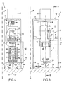
- Fig. 3 and 4 are views, similar to Fig. 1 and 2 , showing an alternative embodiment of the compensation means.
- the Fig. 5 is a view, similar to the Fig. 1 , showing another embodiment of a marking device according to the invention which differs from those illustrated in FIGS. Fig. 1 to 4 in the nature of the kinematics of the displacement of the marking member and in the embodiment of the compensation means, as well as in the fact that it implements laser marking means.
- the Fig. 6 is a schematic view in partial section along the line VI-VI of the Fig. 5 .
- a marking device as schematically illustrated in FIGS. Fig. 1 and 2 and generally designated by the reference 1, comprises a carrier frame 2 which, according to the example shown, has two lateral legs 3, intended to bear on the surface to be marked S.
- the presence of the legs 3 corresponds to a portable embodiment that makes the device 1 may be transported by its user from one place to another, depending on the needs.
- the presence of the legs 3 is not strictly necessary for the realization of a marking device according to the invention which could also be adapted to a bracket, so that the legs 3 would become perfectly useless.
- the device 1 further comprises marking means 4 which, according to the illustrated example, are in the form of an electromagnetic micro-percussion system comprising, as marking member, a marking tip 5, whose end is intended to come to impact the surface S to make hollow conformations or points of impact, as will appear later.
- marking means 4 which, according to the illustrated example, are in the form of an electromagnetic micro-percussion system comprising, as marking member, a marking tip 5, whose end is intended to come to impact the surface S to make hollow conformations or points of impact, as will appear later.
- the marking device 1 further comprises displacement means 10 of the marking member 5.
- the displacement means 10 comprise a translational guiding lane 11, which is connected to the frame 2.
- the translation guiding lane 11 is made in the form of a guide rail. guidance, such as, for example, a commercial guide rail, fixed at both ends to the frame 2.
- the guide way in translation 11 could be carried out in any other way, such as, for example, described in the patent application FR 2,256,833 .
- the guide path 11 is completely connected to the frame, so that it can not know any relative displacement with respect to the latter.
- the displacement means 10 also comprise a carriage 12 which is fitted on the guideway 11, so as to be movable in translation in a direction r, parallel to the plane of displacement P '.
- motor means 13 for translational movement of the carriage.
- These motor means 13 comprise an arm 14 which extends from the carriage 12 and away from the surface S.
- the arm 14 has, at its end opposite the carriage 12, a rack 15 which is parallel to the direction r and which cooperates with a pinion 16 rotated by a motor 17, such as, for example but not exclusively, an electric motor step.
- a motor 17 such as, for example but not exclusively, an electric motor step.
- the displacement means 10 further comprise an oscillating cradle 20 which is adapted to the carriage 12 so as to be able to pivot relative to the latter along an axis ⁇ parallel to the direction ⁇ and therefore perpendicular to the plane P.
- the carriage 12 is placed on the face of the guideway 11 facing the surface S, while the cradle 20 is connected to the carriage 12 on a face of the latter oriented, also, towards the surface to be marked, so that the cradle 20 is opposite the track 11 relative to the carriage 12.
- the marking means 4 and, more particularly, the tip 5 are adapted to the cradle 20, opposite the carriage 12, so that the tip 5 is close to the surface S to be marked, as will be apparent in the following.
- the displacement means 10 further comprise motor means 21 for moving in rotation in both directions of the cradle 20.
- the motor means 21 for rotating the cradle 1 then comprise at least one arm 22 , one end of which is connected to the cradle 20 and the other end of which is situated opposite the first, on the other side of the track. 1.
- the arm 22 has, according to the illustrated example, a general shape in "C".
- the end of the arm 22, which is not connected to the cradle 20, is provided with a toothed sector 23 which cooperates with a pinion 24 driven by a motor 25, such as, for example but not exclusively, an electric motor. step by step.
- the motor 25 is secured to the carriage 12 and, more particularly, fixed on its arm 14, so that all the motor means 21 for rotating the cradle 20 is displaced in translation at the same time. time that the carriage 10 of the marking member formed by the tip 5.
- the displacement means 10 make it possible to ensure, by a control of the motor 17, a translation of the tip 5 parallel to the plane P ' in the direction of the double arrow F 1 , while the control of the motor 25 allows to rotate the tip 5 in both directions, as indicated by the arrows F 2 .
- the combination of the movements according to the arrows F 1 and F 2 defines a marking window whose length is fixed by the amplitude of the translation in the direction ⁇ and whose width is determined by the amplitude of the rotation around the axis ⁇ . It is then possible, when starting the electromagnetic system 4, to impact with the tip 5 any point in the marking window, as defined.
- the invention proposes to use means 30 for compensating the effects of the rotation of the marking member, in this case the tip 5, so as to guarantee the quality of the impacts of the point 5 on the surface S at any point of the marking window.
- These compensation means 30 may be made in different ways, depending, in particular, on the embodiment of the marking system and the kinematics of the displacement means 10.
- the marking system 4 is a system with electromagnetic microphone percussion.
- the system 4 comprises an electromagnetic coil 31 placed in the body 32 of the system 4, said body 32 being fixed to the cradle 20.
- the marking system 4 further comprises a ferromagnetic core 33 disposed inside the the coil 31 and the body 32, to be movable in alternative translation in a marking direction D.
- the ferromagnetic core 33 is then movable between a rest position R, as shown in solid lines at the Fig. 2 , and a marking position M, marked in dashed line also at the Fig. 2 .
- the ferromagnetic core 33 is intended to act on the marking tip 5 to, by its reciprocating movement inside the coil 31, ensure an alternative displacement of the tip 5 and thus allow the realization of a series of micro impacts in the surface S to be marked.
- the marking tip 5 is then also mobile, between a rest position, as illustrated in FIG. Fig. 2 , and a marking position, not shown, in which it is in contact with the surface S. It should be noted that the marking tip 5 is slaved or recalled in the rest position by a spring 34 which tends to maintain, at all moment, the end of the tip 5 opposite the surface S in contact with the movable core 33. Given the presence of the spring 34, the rest position of the tip 5 corresponds to and is defined by the rest position of the core 33.
- the compensation means 30 comprise a movable stop 40 against which the core 31 bears in the rest position R.
- This movable stop 40 placed at the rear of the core, the opposite of the tip 5, is integral with a finger 41 which extends from the stop 40 to the carriage 12 and which then forms a cam which cooperates with a cam path 42 arranged in the carriage 12.
- the path 42 is then shaped so that, during the rotation of the cradle 20 and thus the finger 41 which is integral therewith, the stop 40 moves, so as to maintain substantially constant the distance between the end of the tip 5 at rest and the surface S to be marked, this distance being measured perpendicularly to the surface to be marked.
- the place of displacement of the rest position R of the end of the tip 5 is a surface S 1 substantially parallel to the surface S to be marked whereas, in the absence of the means of compensation, the rest position of the tip would describe a cylinder of revolution.
- the rotation compensation means do not necessarily comprise a cam, such as the finger 41, and a cam path, such as the surface 42.
- Fig. 3 and 4 show an alternative embodiment of a marking device according to the invention adopting, for the displacement means 10 of the marking member, the same kinematics as that described in relation to the Fig. 1 and 2 but for which the means for compensating the rotation of the marking member are made differently.
- the compensation means comprise means 45 for defining a reference surface S R which, in the example shown, is substantially parallel to the surface S, without this being here a strictly necessary characteristic the embodiment of the invention.
- the means 45 for defining the reference surface S R comprise a bracket which is completely connected to the carriage 12 and which carries, at its end opposite the carriage 12, a flat lug 47 in which is arranged a straight groove 48 of axis perpendicular to the axis of rotation ⁇ .
- the marking tip 5 passes into this groove 48 where it is able to move during the rotation of the cradle 20.
- the marking tip 5 then comprises, as means 49 of connection with the reference surface S R , a ball 49 maintained by the spring 34, against the surface S R , when the marking tip 5 is in the rest position.
- the surface definition means S R automatically induce, during the rotation of the cradle 20 , a translation of the tip 5 in the rest position in a direction ⁇ , here coincides with the marking direction D.
- the means for compensating for the rotation of the marking member can be implemented in the context of other kinematics of the moving means than those described in relation to the Fig. 1 and 2 .
- FIG. 5 and 6 show an embodiment of a marking device according to the invention, which incorporates means for compensating the rotation of the marking member and the kinematics of the displacement means 10 differs from that described above.
- the marking means 4 are not micro percussion but laser and then comprise a laser source 51, such as, for example, a pulsed laser source whose radius is conveyed by an optical fiber or a beam of optical fiber 52 to a marking lens 53 which constitutes, in the sense of the invention, the marking member of the device 1.
- a laser source 51 such as, for example, a pulsed laser source whose radius is conveyed by an optical fiber or a beam of optical fiber 52 to a marking lens 53 which constitutes, in the sense of the invention, the marking member of the device 1.
- the displacement means 10 comprise a translation guide track 55 which has a direction r, parallel to the plane P ' and to the surface to be marked S, and which is adapted to the frame, so as to be mobile at least in rotation around the axis ⁇ .
- the translation guideway 55 is fixed at each of its ends to an arm 56 which is also part of the means for moving the guideway 55 in rotation , as will be apparent from FIG. the following.
- Each arm 56 comprises, on the one hand, an elongate rectilinear slot 57 of axis ⁇ parallel to the marking direction D defined by the laser beam 58.
- Each light 57 is then engaged on a pin 59 which is completely connected. to the frame 2, so that the pin 59 and the corresponding light 57 define a link with two degrees of freedom, a degree of freedom in rotation and a degree of freedom in translation.
- Each arm 56 comprises, on the other hand, a window 60 which is curved and forms a cam path for a cylindrical cam 61, connected to the frame and engaged in the window 55.
- one of the arms 56 in this case the left arm on the Fig. 5 , furthermore, has a toothed sector 62 which cooperates with a pinion 63 driven by a motor 64, such as, for example, a stepping electric motor.
- a motor 64 such as, for example, a stepping electric motor.
- the motor 64 is pivotally mounted on the frame 2 and the continuity of the cooperation of the pinion 63 with the toothed sector 62 is provided by at least one spring 65.
- the displacement means 10 also include a carriage 66 which is adapted on the guideway 55 to be movable in translation along the latter and on which the marking member, in this case the marking lens 53 is adapted.
- the carriage 66 is also associated with translational displacement means 67 which, according to the illustrated example, comprise a rack 68 fitted to an arm 69 integral with the carriage 66 and cooperating with a pinion 70 driven by a motor 71, such as an electric motor step by step, integral with the guideway 55.
- control of the motor 71 causes a translation of the carriage 66 and thus of the marking lens, parallel to the track 55, while the control of the motor 64 causes a rotation of the arms 56 and thus of the guide track 55 which pivots. , so that the marking lens 53 is also rotated.
- each window 60 is then shaped to induce, during the rotation of the guideway 55, an axis translation ⁇ of this same guideway and therefore of the marking lens 53, so as to compensate for the effects of rotation.
- each window 60 will be shaped such that the distance between the surface to be marked S and the optical center O of the marking lens 53 is substantially constant and equal to the focal length of the lens 53. , this distance being measured perpendicularly to the surface to be marked S.
- the marker lens compensation means and, more particularly, its optical center move in a plane or in a surface parallel to the surface to be engraved, when the marking laser spot describes the marking window, this surface being located at a distance measured perpendicularly to the surface to be marked is substantially equal to the focal length of the marking lens. There is then only a partial compensation of the influence of the rotation on the position of the marking member.
- the compensation means and, more particularly, the windows 60 will then be adapted so that the distance between the marking point and the optical center of the lens, this time measured along the line defined by the laser beam, is equal to the focal length.
- the locus of displacement of the optical center O of the marking lens 53 will no longer be a plane but will be a surface tangent to the plane, as defined above, and located between this plane and the surface to be marked S.
- the motor 25, ensuring the oscillation of the marking system 4 about the axis ⁇ is secured to the carriage 12 via the arm 14.
- the kinematics adopted in the examples of the Fig. 1 to 4 , has the advantage of allowing, in order to reduce the mass of the moving elements, to fix the motor 25 directly on the frame 2.
- the rotation drive of the marking system 4 is then ensured by an elongated pinion which extends on a part of the width of the frame parallel to the axis ⁇ and along which the toothed sector 23 moves in translation. Insofar as the spline teeth of the pinion are parallel to the axis ⁇ , there are no obstacles to the translation of the carriage 12.
- the displacement of the marking member is ensured by the combination of a translation and a rotation axis substantially perpendicular to the translation axis.
- the displacement of the marking member could also be obtained by the combination of two rotations of perpendicular axes, the compensation means will then be adapted to automatically compensate for the effects of each of the rotations along these two axes .
- the displacement of the marking member 5, 53, parallel to the plane of movement P ' is ensured by at least one rotation of the marking member around an axis ⁇ ' parallel to the other plane P of movement.
Landscapes
- Engineering & Computer Science (AREA)
- Mechanical Engineering (AREA)
- Laser Beam Processing (AREA)
- Testing Of Balance (AREA)
- Printers Characterized By Their Purpose (AREA)
- Automobile Manufacture Line, Endless Track Vehicle, Trailer (AREA)
Claims (10)
- Vorrichtung für die Markierung einer Fläche (S), umfassend:- einen Tragrahmen (2),- Markierungsmittel (4), die ein Markierungsorgan (5) umfassen, welches dazu ausgelegt ist, einen Punkt oder eine im Wesentlichen punktuelle Markierung auszubilden, und- Mittel zur Bewegung (10) des Markierungsorgans (5) parallel zu zwei Bewegungsebenen (P, P'), die zueinander und zu der zu markierenden Fläche (S) senkrecht verlaufen, um auf der zu markierenden Fläche zweidimensionale Zeichen innerhalb eines durch den Umfang der Bewegungen des Markierungsorgans definierten Markierungsfensters herzustellen, wobei die Bewegung des Markierungsorgans parallel zu der Bewegungsebene (P) durch wenigstens eine Rotation des Markierungsorgans um eine zu der anderen Bewegungsebene (P') parallel verlaufende Achse (Ω) sichergestellt ist,dadurch gekennzeichnet, dass sie Mittel (30) zum wenigstens teilweisen Kompensieren des Einflusses der Rotation auf den Abstand zwischen dem Markierungsorgan und der Markierungsstelle auf der zu markierenden Fläche umfasst,
und dass die Mittel zur Bewegung des Markierungsorgans wenigstens umfassen:- eine Bahn (11), die mit dem Rahmen (2) vollstandig verbunden ist und die die Verschiebeführung eines Schlittens (12) entlang einer Richtung (Γ) parallel zu der Ebene (P') und zu der zu markierenden Fläche (S) sicherstellt,- Antriebsmittel (13) zur Verschiebebewegung in den beiden Richtungen des Schlittens (12) entlang der Führungsbahn (11),- ein Schwinggestell (20), das wenigstens das Markierungsorgan (5, 53) trägt und das an dem Schlitten (12) angebracht ist, um wenigstens gegenüber dem Schlitten um die zu der Richtung (Γ) parallel verlaufende Achse (Ω) zu schwenken, und- Antriebsmittel (21) zur Drehbewegung in den beiden Richtungen des Gestells um die Achse (Ω). - Markierungsvorrichtung nach Anspruch 1, dadurch gekennzeichnet, dass die Antriebsmittel (21) zur Drehbewegung mit dem Schlitten (12) fest verbunden sind.
- Markierungsvorrichtung nach Anspruch 1 oder 2, dadurch gekennzeichnet, dass:- das Gestell (20) mit dem Schlitten (12) an einer der zu markierenden Fläche (S) zugewandten Seite verbunden ist,- das Markierungsorgan von dem Schlitten (12) abgewandt an dem Gestell (20) angebracht ist,- die Antriebsmittel (21) zur Drehbewegung des Gestells wenigstens einen Arm (22) umfassen, von dem eines der Enden mit dem Gestell (20) verbunden ist und dessen anderes Ende dem ersten gegenüberliegt und mit einem Zahnsegment (23) versehen ist, das mit einem durch einen Motor (25) drehangetriebenen Ritzel (24) zusammenwirkt.
- Markierungsvorrichtung nach einem der Ansprüche 1 bis 3, dadurch gekennzeichnet, dass die Markierungsmittel (4) ein Mikroschlagsystem umfassen, das als Markierungsorgan eine Markierungsspitze (5) umfasst, die entlang einer sogenannten Markierungsrichtung (D) zwischen einer Ruheposition und einer Markierungsposition auf und ab verschiebebeweglich ist, wobei die Ruheposition der Markierungsspitze der Bezug für die Messung des Abstandes zwischen einerseits dem Markierungsorgan und andererseits der zu markierenden Fläche (S) oder der Markierungsstelle ist.
- Markierungsvorrichtung nach einem der Ansprüche 1 bis 4, dadurch gekennzeichnet, dass die Kompensationsmittel (30) dazu ausgelegt sind, den senkrecht zu der zu markierenden Fläche gemessenen Abstand zwischen dem Markierungsorgan und der zu markierenden Fläche auf einem konstanten Wert zu halten.
- Markierungsvorrichtung nach Anspruch 5, dadurch gekennzeichnet, dass die Kompensationsmittel (30) dazu ausgelegt sind, den Abstand zwischen dem Markierungsorgan und der Markierungsstelle auf der zu markierenden Fläche auf einem konstanten Wert zu halten.
- Markierungsvorrichtung nach einem der Ansprüche 3 bis 6, dadurch gekennzeichnet, dass:- das Mikroschlag-Markierungssystem (4) eine elektromagnetische Spule (31) umfasst, innerhalb derer ein ferromagnetischer Kern (33) angeordnet ist, der auf die Markierungsspitze (5) wirkt und der in der Spule (31) zwischen einer Ruhe- (R) und Markierungsposition (M) verschiebebeweglich ist, und- die Kompensationsmittel (30) einen beweglichen Anschlag (40) umfassen, an dem der Kern (33) in der Ruheposition (R) abgestützt ist und der einem einen Nocken bildenden Finger (41) zugeordnet ist, welcher mit einer mit dem Schlitten (12) fest verbundenen Kurvenbahn (42) zusammenwirkt, so dass eine Rotation des Gestells (20) zu einer Bewegung des Fingers (41) entlang der Kurvenbahn (42) führt, deren Profil dazu ausgelegt ist, die Ruheposition (R) des Kerns (33) und der Markierungsspitze (5) in Abhängigkeit von der Winkelstellung des Gestells (20) zu verändern.
- Markierungsvorrichtung nach einem der Ansprüche 1 bis 7, dadurch gekennzeichnet, dass die Kompensationsmittel (30) dazu ausgelegt sind, eine Verschiebung des Markierungsorgans (5, 53) gegenüber der Achse (Ω) und entlang einer zu der Achse (Ω) senkrechten Richtung (Δ) während der Rotation des Markierungsorgans (5, 53) um die Achse (Ω) zu bewirken.
- Markierungsvorrichtung nach Anspruch 8, dadurch gekennzeichnet, dass die Kompensationsmittel (30) wenigstens einen Nocken (61) umfassen, der mit einer Kurvenbahn (60) zusammenwirkt, deren Profil dazu ausgelegt ist, die Verschiebung des Organs entlang der Richtung (Δ) zu bewirken.
- Markierungsvorrichtung nach Anspruch 9, dadurch gekennzeichnet, dass die Kompensationsmittel (30) wenigstens umfassen:- Mittel (45) zur Definition einer Bezugsfläche (SR), und- Mittel (40) zur Verbindung des Markierungsorgans (5) mit der Bezugsfläche (SR), um die Verschiebung des Markierungsorgans (5) entlang der Richtung (Δ) zu bewirken.
Applications Claiming Priority (3)
| Application Number | Priority Date | Filing Date | Title |
|---|---|---|---|
| FR0409655A FR2875172B3 (fr) | 2004-09-10 | 2004-09-10 | Dispositif de marquage |
| FR0410987A FR2875173B1 (fr) | 2004-09-10 | 2004-10-18 | Dispositif de marquage |
| PCT/FR2005/002246 WO2006030117A1 (fr) | 2004-09-10 | 2005-09-09 | Dispositif de marquage |
Publications (2)
| Publication Number | Publication Date |
|---|---|
| EP1809488A1 EP1809488A1 (de) | 2007-07-25 |
| EP1809488B1 true EP1809488B1 (de) | 2014-06-18 |
Family
ID=35744695
Family Applications (1)
| Application Number | Title | Priority Date | Filing Date |
|---|---|---|---|
| EP05805566.6A Not-in-force EP1809488B1 (de) | 2004-09-10 | 2005-09-09 | Markierungsvorrichtung |
Country Status (4)
| Country | Link |
|---|---|
| US (1) | US8037815B2 (de) |
| EP (1) | EP1809488B1 (de) |
| FR (1) | FR2875173B1 (de) |
| WO (1) | WO2006030117A1 (de) |
Families Citing this family (6)
| Publication number | Priority date | Publication date | Assignee | Title |
|---|---|---|---|---|
| FR2875173B1 (fr) | 2004-09-10 | 2006-12-29 | Sic Marking Soc Par Actions Si | Dispositif de marquage |
| FR2898535B1 (fr) * | 2006-03-16 | 2008-07-04 | Sic Marking Soc Par Actions Si | Dispositif de marquage a moteurs mobiles |
| CN102765264B (zh) * | 2012-07-27 | 2014-09-24 | 江苏乐基重工机械有限公司 | 钢材在线自动打钢印机 |
| CN103737322A (zh) * | 2013-12-20 | 2014-04-23 | 柳州科尔特锻造机械有限公司 | 轮辐打标识倒角机 |
| FR3024674B1 (fr) * | 2014-08-08 | 2016-08-26 | Sic Marking Group | Appareil portatif pour le marquage d'une surface |
| FR3029443B1 (fr) * | 2014-12-08 | 2017-05-26 | Auvray | Systeme et procede de marquage d'un vehicule |
Family Cites Families (10)
| Publication number | Priority date | Publication date | Assignee | Title |
|---|---|---|---|---|
| DE1552393B1 (de) * | 1966-10-31 | 1969-10-16 | Froriep Gmbh Maschf | Schwerwerkzeugmaschine |
| CH573315A5 (de) | 1974-01-08 | 1976-03-15 | Tesalon Anstalt | |
| DE2502961A1 (de) * | 1975-01-24 | 1976-07-29 | Precitec Gmbh | Vorrichtung zum abgleich des widerstands-werts einer elektrisch leitfaehigen schicht |
| IT1179924B (it) * | 1984-05-22 | 1987-09-16 | Prima Progetti Spa | Testa focalizzatrice per una macchina da taglio a raggi laser |
| DE3735422A1 (de) * | 1987-10-20 | 1989-05-11 | Borries Otto Kg | Nadelpraegevorrichtung |
| FR2639860B1 (fr) * | 1988-12-01 | 1991-01-25 | Technifor Sarl | Dispositif de marquage par micro-percussion |
| JP3295110B2 (ja) * | 1991-10-07 | 2002-06-24 | 東芝機械株式会社 | サドルスイベルヘッド |
| ES2133227B1 (es) * | 1996-11-07 | 2000-04-01 | Echevarria Lizarazu Pio | Maquina grabadora por impacto o rayado. |
| FR2839860A1 (fr) | 2001-11-23 | 2003-11-28 | Victor Tsemo | Modele de casquette a elements interchangeables |
| FR2875173B1 (fr) | 2004-09-10 | 2006-12-29 | Sic Marking Soc Par Actions Si | Dispositif de marquage |
-
2004
- 2004-10-18 FR FR0410987A patent/FR2875173B1/fr not_active Expired - Fee Related
-
2005
- 2005-09-09 US US11/662,275 patent/US8037815B2/en not_active Expired - Fee Related
- 2005-09-09 WO PCT/FR2005/002246 patent/WO2006030117A1/fr active Application Filing
- 2005-09-09 EP EP05805566.6A patent/EP1809488B1/de not_active Not-in-force
Also Published As
| Publication number | Publication date |
|---|---|
| EP1809488A1 (de) | 2007-07-25 |
| FR2875173B1 (fr) | 2006-12-29 |
| FR2875173A1 (fr) | 2006-03-17 |
| US20080302254A1 (en) | 2008-12-11 |
| WO2006030117A1 (fr) | 2006-03-23 |
| US8037815B2 (en) | 2011-10-18 |
Similar Documents
| Publication | Publication Date | Title |
|---|---|---|
| EP1809488B1 (de) | Markierungsvorrichtung | |
| EP0538106B1 (de) | Motorisiertes Fensterrolle für gebogenes Fenster | |
| EP0371896B1 (de) | Mikroschlaggerät für Markierung | |
| EP0439975B1 (de) | Mechanisches System zur automatischen Führung eines oder mehrerer Brenner eines Lichtbogenschweissgerätes | |
| FR2460762A1 (fr) | Dispositif pour la commande de l'orientation d'un outil ou d'un element analogue par rapport a une piece | |
| FR2910980A1 (fr) | Appareil de blocage de lentille | |
| FR2684037A1 (fr) | Dispositif automatique pour couper le papier dans un traceur. | |
| FR2659717A1 (fr) | Procede et dispositif pour animer une surface d'un mouvement de va-et-vient dans un plan. | |
| FR2875172A1 (fr) | Dispositif de marquage | |
| EP1401746A2 (de) | Vorrichtung zum zuführen von teilen zu einer maschine | |
| EP1637316B1 (de) | Vorrichtung zum Falten der Laschen eines Schachtelzuschnittes | |
| EP1150632B1 (de) | Chirurgische vorrichtung zur durchführung eines lamellären hornhautschnittes | |
| FR2638993A1 (fr) | Dispositif de decapage de deux bords de tole metallique a souder | |
| FR2541603A1 (fr) | Appareil a cintrer | |
| WO2001003894A1 (fr) | Dispositif de positionnement d'une plaque sur un cylindre a fixation magnetique | |
| EP0478439B1 (de) | Maschine zur Herstellung von geschliffenen Schrauben ausgehend von Stäben | |
| FR2898535A1 (fr) | Dispositif de marquage a moteurs mobiles | |
| EP0961151B1 (de) | Optisches Stellglied zur Führung eines einfallenden Lichtstrahls auf eine sich ausserhalb des Stellglieds befindliche, feststehende Oberfläche | |
| FR2526415A1 (fr) | Dispositif de commande simultanee de l'ensemble des outils-traceurs tracant des traits longitudinaux paralleles sur une bande de verre en mouvement | |
| WO2006131654A2 (fr) | Dispositif de marquage comportant un mecanisme d'entrainement perfectionne | |
| CH617516A5 (de) | ||
| BE898452A (fr) | Machine de sciage d'un materiau pierreux a table mobile. | |
| WO2004060699A1 (fr) | Machine a graver polaire | |
| FR2917662A1 (fr) | Dispositif de support et d'entrainement de tubes, en particulier de tubes de faible epaisseur de paroi, en fin d'enroulement et pendant la coupe a la volee | |
| FR2732289A1 (fr) | Mecanisme d'essuie-glace a balayage lineaire alterne |
Legal Events
| Date | Code | Title | Description |
|---|---|---|---|
| PUAI | Public reference made under article 153(3) epc to a published international application that has entered the european phase |
Free format text: ORIGINAL CODE: 0009012 |
|
| 17P | Request for examination filed |
Effective date: 20070410 |
|
| AK | Designated contracting states |
Kind code of ref document: A1 Designated state(s): AT BE BG CH CY CZ DE DK EE ES FI FR GB GR HU IE IS IT LI LT LU LV MC NL PL PT RO SE SI SK TR |
|
| DAX | Request for extension of the european patent (deleted) | ||
| 17Q | First examination report despatched |
Effective date: 20110817 |
|
| GRAP | Despatch of communication of intention to grant a patent |
Free format text: ORIGINAL CODE: EPIDOSNIGR1 |
|
| INTG | Intention to grant announced |
Effective date: 20140116 |
|
| GRAS | Grant fee paid |
Free format text: ORIGINAL CODE: EPIDOSNIGR3 |
|
| GRAA | (expected) grant |
Free format text: ORIGINAL CODE: 0009210 |
|
| AK | Designated contracting states |
Kind code of ref document: B1 Designated state(s): AT BE BG CH CY CZ DE DK EE ES FI FR GB GR HU IE IS IT LI LT LU LV MC NL PL PT RO SE SI SK TR |
|
| REG | Reference to a national code |
Ref country code: GB Ref legal event code: FG4D Free format text: NOT ENGLISH |
|
| REG | Reference to a national code |
Ref country code: CH Ref legal event code: EP |
|
| REG | Reference to a national code |
Ref country code: AT Ref legal event code: REF Ref document number: 673110 Country of ref document: AT Kind code of ref document: T Effective date: 20140715 |
|
| REG | Reference to a national code |
Ref country code: IE Ref legal event code: FG4D Free format text: LANGUAGE OF EP DOCUMENT: FRENCH |
|
| REG | Reference to a national code |
Ref country code: DE Ref legal event code: R096 Ref document number: 602005043970 Country of ref document: DE Effective date: 20140731 |
|
| PG25 | Lapsed in a contracting state [announced via postgrant information from national office to epo] |
Ref country code: FI Free format text: LAPSE BECAUSE OF FAILURE TO SUBMIT A TRANSLATION OF THE DESCRIPTION OR TO PAY THE FEE WITHIN THE PRESCRIBED TIME-LIMIT Effective date: 20140618 Ref country code: LT Free format text: LAPSE BECAUSE OF FAILURE TO SUBMIT A TRANSLATION OF THE DESCRIPTION OR TO PAY THE FEE WITHIN THE PRESCRIBED TIME-LIMIT Effective date: 20140618 Ref country code: CY Free format text: LAPSE BECAUSE OF FAILURE TO SUBMIT A TRANSLATION OF THE DESCRIPTION OR TO PAY THE FEE WITHIN THE PRESCRIBED TIME-LIMIT Effective date: 20140618 Ref country code: GR Free format text: LAPSE BECAUSE OF FAILURE TO SUBMIT A TRANSLATION OF THE DESCRIPTION OR TO PAY THE FEE WITHIN THE PRESCRIBED TIME-LIMIT Effective date: 20140919 |
|
| REG | Reference to a national code |
Ref country code: NL Ref legal event code: VDEP Effective date: 20140618 |
|
| REG | Reference to a national code |
Ref country code: AT Ref legal event code: MK05 Ref document number: 673110 Country of ref document: AT Kind code of ref document: T Effective date: 20140618 |
|
| REG | Reference to a national code |
Ref country code: LT Ref legal event code: MG4D |
|
| PG25 | Lapsed in a contracting state [announced via postgrant information from national office to epo] |
Ref country code: SE Free format text: LAPSE BECAUSE OF FAILURE TO SUBMIT A TRANSLATION OF THE DESCRIPTION OR TO PAY THE FEE WITHIN THE PRESCRIBED TIME-LIMIT Effective date: 20140618 Ref country code: LV Free format text: LAPSE BECAUSE OF FAILURE TO SUBMIT A TRANSLATION OF THE DESCRIPTION OR TO PAY THE FEE WITHIN THE PRESCRIBED TIME-LIMIT Effective date: 20140618 |
|
| PG25 | Lapsed in a contracting state [announced via postgrant information from national office to epo] |
Ref country code: RO Free format text: LAPSE BECAUSE OF FAILURE TO SUBMIT A TRANSLATION OF THE DESCRIPTION OR TO PAY THE FEE WITHIN THE PRESCRIBED TIME-LIMIT Effective date: 20140618 Ref country code: SK Free format text: LAPSE BECAUSE OF FAILURE TO SUBMIT A TRANSLATION OF THE DESCRIPTION OR TO PAY THE FEE WITHIN THE PRESCRIBED TIME-LIMIT Effective date: 20140618 Ref country code: ES Free format text: LAPSE BECAUSE OF FAILURE TO SUBMIT A TRANSLATION OF THE DESCRIPTION OR TO PAY THE FEE WITHIN THE PRESCRIBED TIME-LIMIT Effective date: 20140618 Ref country code: CZ Free format text: LAPSE BECAUSE OF FAILURE TO SUBMIT A TRANSLATION OF THE DESCRIPTION OR TO PAY THE FEE WITHIN THE PRESCRIBED TIME-LIMIT Effective date: 20140618 Ref country code: EE Free format text: LAPSE BECAUSE OF FAILURE TO SUBMIT A TRANSLATION OF THE DESCRIPTION OR TO PAY THE FEE WITHIN THE PRESCRIBED TIME-LIMIT Effective date: 20140618 |
|
| PG25 | Lapsed in a contracting state [announced via postgrant information from national office to epo] |
Ref country code: PL Free format text: LAPSE BECAUSE OF FAILURE TO SUBMIT A TRANSLATION OF THE DESCRIPTION OR TO PAY THE FEE WITHIN THE PRESCRIBED TIME-LIMIT Effective date: 20140618 Ref country code: AT Free format text: LAPSE BECAUSE OF FAILURE TO SUBMIT A TRANSLATION OF THE DESCRIPTION OR TO PAY THE FEE WITHIN THE PRESCRIBED TIME-LIMIT Effective date: 20140618 Ref country code: NL Free format text: LAPSE BECAUSE OF FAILURE TO SUBMIT A TRANSLATION OF THE DESCRIPTION OR TO PAY THE FEE WITHIN THE PRESCRIBED TIME-LIMIT Effective date: 20140618 Ref country code: IS Free format text: LAPSE BECAUSE OF FAILURE TO SUBMIT A TRANSLATION OF THE DESCRIPTION OR TO PAY THE FEE WITHIN THE PRESCRIBED TIME-LIMIT Effective date: 20141018 |
|
| REG | Reference to a national code |
Ref country code: DE Ref legal event code: R097 Ref document number: 602005043970 Country of ref document: DE |
|
| PLBE | No opposition filed within time limit |
Free format text: ORIGINAL CODE: 0009261 |
|
| STAA | Information on the status of an ep patent application or granted ep patent |
Free format text: STATUS: NO OPPOSITION FILED WITHIN TIME LIMIT |
|
| PG25 | Lapsed in a contracting state [announced via postgrant information from national office to epo] |
Ref country code: LU Free format text: LAPSE BECAUSE OF FAILURE TO SUBMIT A TRANSLATION OF THE DESCRIPTION OR TO PAY THE FEE WITHIN THE PRESCRIBED TIME-LIMIT Effective date: 20140909 Ref country code: MC Free format text: LAPSE BECAUSE OF FAILURE TO SUBMIT A TRANSLATION OF THE DESCRIPTION OR TO PAY THE FEE WITHIN THE PRESCRIBED TIME-LIMIT Effective date: 20140618 Ref country code: DK Free format text: LAPSE BECAUSE OF FAILURE TO SUBMIT A TRANSLATION OF THE DESCRIPTION OR TO PAY THE FEE WITHIN THE PRESCRIBED TIME-LIMIT Effective date: 20140618 |
|
| REG | Reference to a national code |
Ref country code: CH Ref legal event code: PL |
|
| 26N | No opposition filed |
Effective date: 20150319 |
|
| REG | Reference to a national code |
Ref country code: IE Ref legal event code: MM4A |
|
| PG25 | Lapsed in a contracting state [announced via postgrant information from national office to epo] |
Ref country code: BE Free format text: LAPSE BECAUSE OF NON-PAYMENT OF DUE FEES Effective date: 20140930 |
|
| PG25 | Lapsed in a contracting state [announced via postgrant information from national office to epo] |
Ref country code: SI Free format text: LAPSE BECAUSE OF FAILURE TO SUBMIT A TRANSLATION OF THE DESCRIPTION OR TO PAY THE FEE WITHIN THE PRESCRIBED TIME-LIMIT Effective date: 20140618 Ref country code: LI Free format text: LAPSE BECAUSE OF NON-PAYMENT OF DUE FEES Effective date: 20140930 Ref country code: CH Free format text: LAPSE BECAUSE OF NON-PAYMENT OF DUE FEES Effective date: 20140930 |
|
| PG25 | Lapsed in a contracting state [announced via postgrant information from national office to epo] |
Ref country code: IE Free format text: LAPSE BECAUSE OF NON-PAYMENT OF DUE FEES Effective date: 20140909 |
|
| PG25 | Lapsed in a contracting state [announced via postgrant information from national office to epo] |
Ref country code: BG Free format text: LAPSE BECAUSE OF FAILURE TO SUBMIT A TRANSLATION OF THE DESCRIPTION OR TO PAY THE FEE WITHIN THE PRESCRIBED TIME-LIMIT Effective date: 20140618 |
|
| PG25 | Lapsed in a contracting state [announced via postgrant information from national office to epo] |
Ref country code: PT Free format text: LAPSE BECAUSE OF FAILURE TO SUBMIT A TRANSLATION OF THE DESCRIPTION OR TO PAY THE FEE WITHIN THE PRESCRIBED TIME-LIMIT Effective date: 20140618 |
|
| PG25 | Lapsed in a contracting state [announced via postgrant information from national office to epo] |
Ref country code: TR Free format text: LAPSE BECAUSE OF FAILURE TO SUBMIT A TRANSLATION OF THE DESCRIPTION OR TO PAY THE FEE WITHIN THE PRESCRIBED TIME-LIMIT Effective date: 20140618 Ref country code: HU Free format text: LAPSE BECAUSE OF FAILURE TO SUBMIT A TRANSLATION OF THE DESCRIPTION OR TO PAY THE FEE WITHIN THE PRESCRIBED TIME-LIMIT; INVALID AB INITIO Effective date: 20050909 |
|
| REG | Reference to a national code |
Ref country code: FR Ref legal event code: PLFP Year of fee payment: 12 |
|
| PGFP | Annual fee paid to national office [announced via postgrant information from national office to epo] |
Ref country code: IT Payment date: 20160913 Year of fee payment: 12 Ref country code: GB Payment date: 20160916 Year of fee payment: 12 Ref country code: DE Payment date: 20160914 Year of fee payment: 12 |
|
| PGFP | Annual fee paid to national office [announced via postgrant information from national office to epo] |
Ref country code: FR Payment date: 20160801 Year of fee payment: 12 |
|
| REG | Reference to a national code |
Ref country code: DE Ref legal event code: R119 Ref document number: 602005043970 Country of ref document: DE |
|
| GBPC | Gb: european patent ceased through non-payment of renewal fee |
Effective date: 20170909 |
|
| REG | Reference to a national code |
Ref country code: FR Ref legal event code: ST Effective date: 20180531 |
|
| PG25 | Lapsed in a contracting state [announced via postgrant information from national office to epo] |
Ref country code: GB Free format text: LAPSE BECAUSE OF NON-PAYMENT OF DUE FEES Effective date: 20170909 Ref country code: DE Free format text: LAPSE BECAUSE OF NON-PAYMENT OF DUE FEES Effective date: 20180404 |
|
| PG25 | Lapsed in a contracting state [announced via postgrant information from national office to epo] |
Ref country code: IT Free format text: LAPSE BECAUSE OF NON-PAYMENT OF DUE FEES Effective date: 20170909 Ref country code: FR Free format text: LAPSE BECAUSE OF NON-PAYMENT OF DUE FEES Effective date: 20171002 |