EP1808634A1 - Fixture to mount a device - Google Patents
Fixture to mount a device Download PDFInfo
- Publication number
- EP1808634A1 EP1808634A1 EP06000550A EP06000550A EP1808634A1 EP 1808634 A1 EP1808634 A1 EP 1808634A1 EP 06000550 A EP06000550 A EP 06000550A EP 06000550 A EP06000550 A EP 06000550A EP 1808634 A1 EP1808634 A1 EP 1808634A1
- Authority
- EP
- European Patent Office
- Prior art keywords
- holding part
- mounting part
- screw
- groove
- screw head
- Prior art date
- Legal status (The legal status is an assumption and is not a legal conclusion. Google has not performed a legal analysis and makes no representation as to the accuracy of the status listed.)
- Granted
Links
- 238000000034 method Methods 0.000 description 2
- 238000001035 drying Methods 0.000 description 1
- 230000003116 impacting effect Effects 0.000 description 1
- 230000007774 longterm Effects 0.000 description 1
- 230000005855 radiation Effects 0.000 description 1
Images

Classifications
-
- F—MECHANICAL ENGINEERING; LIGHTING; HEATING; WEAPONS; BLASTING
- F16—ENGINEERING ELEMENTS AND UNITS; GENERAL MEASURES FOR PRODUCING AND MAINTAINING EFFECTIVE FUNCTIONING OF MACHINES OR INSTALLATIONS; THERMAL INSULATION IN GENERAL
- F16M—FRAMES, CASINGS OR BEDS OF ENGINES, MACHINES OR APPARATUS, NOT SPECIFIC TO ENGINES, MACHINES OR APPARATUS PROVIDED FOR ELSEWHERE; STANDS; SUPPORTS
- F16M11/00—Stands or trestles as supports for apparatus or articles placed thereon ; Stands for scientific apparatus such as gravitational force meters
- F16M11/02—Heads
- F16M11/04—Means for attachment of apparatus; Means allowing adjustment of the apparatus relatively to the stand
- F16M11/06—Means for attachment of apparatus; Means allowing adjustment of the apparatus relatively to the stand allowing pivoting
-
- F—MECHANICAL ENGINEERING; LIGHTING; HEATING; WEAPONS; BLASTING
- F16—ENGINEERING ELEMENTS AND UNITS; GENERAL MEASURES FOR PRODUCING AND MAINTAINING EFFECTIVE FUNCTIONING OF MACHINES OR INSTALLATIONS; THERMAL INSULATION IN GENERAL
- F16M—FRAMES, CASINGS OR BEDS OF ENGINES, MACHINES OR APPARATUS, NOT SPECIFIC TO ENGINES, MACHINES OR APPARATUS PROVIDED FOR ELSEWHERE; STANDS; SUPPORTS
- F16M13/00—Other supports for positioning apparatus or articles; Means for steadying hand-held apparatus or articles
- F16M13/02—Other supports for positioning apparatus or articles; Means for steadying hand-held apparatus or articles for supporting on, or attaching to, an object, e.g. tree, gate, window-frame, cycle
- F16M13/027—Ceiling supports
Definitions
- the object of the application is based on a fixture, in particular, with a swiveling arm for a support system to mount a medical or salon-technical device.
- tripod stands, ceiling mounts, and wall systems are well known to which medical devices, for example, supply stations or salon-technical devices, e.g. drying hoods or infrared radiation devices, are mounted.
- a swiveling arm is used to swivel the device to a specific location.
- this type of device comprises a holding part and a mounting part mounted on the holding part.
- the holding part is connected to a stationary support, in particular, a tripod stand leg of a ceiling mount or a wall mount.
- the mounting part is rotatably connected to the holding part, which holds the device. The device places a load on the mounting part and therefore the holding part.
- the securing mechanism has a screw with a screw head, and the screw extends into the holding part to support the securing mechanism.
- the known fixture has the disadvantage in that the securing mechanism increases friction of the fixture if the holding part is rotated relative to the mounting part.
- the object of the present invention is to provide a solution for this disadvantage.
- the object is achieved in accordance with the part of Claim 1 as indicated.
- the screw is screwed into the holding part or the mounting part.
- the screw head projects into a groove of a bushing of the other part, that is, of the mounting part or the holding part.
- the screw head can move freely in the groove with a relative rotation between the holding part and the mounting part.
- the groove is bordered by an upper surface against which the screw head impacts if the connection between the holding part and the mounting part fails.
- the suggested fixture has the advantage that the securing mechanism does not disturb the movements of the fixture if there is a functional connection, because the screw head can move back and forth freely in the groove.
- the holding part is not held by the screw head at the mounting part until there is a failure in the connection, when the holding part lowers with respect to the mounting part.
- the fixture becomes difficult to move, because the screw head supports the device, and the device places a load on the screw head via the upper surface of the groove. The surface moves with a great amount of friction via the screw head. In this process, the thread of the screw is not stressed to any great extent.
- the person using the fixture notices the connection failure/joint failure due to the fixture's lack of ease in movement and due to the visible gap, which is caused by the resulting travel movement between the holding part and the mounting part.
- a bolt, a pin, a rivet, or other miscellaneous retaining elements will also fulfill the function of a screw with thread even if one of such retaining elements does not have a thread.
- An end of the retaining element that projects outwards corresponds to the screw head.
- An MLF screw is particularly suitable.
- the screw can be mounted via a slot bordering the groove, whereby the screw can be screwed into an inner thread (Claim 4) or a retaining element is partially inserted into a drilled hole.
- the screw head has a wedge-shaped edge (Claim 3), then the screw head is wedged on the surface of the groove when the securing mechanism is used. It can then be concluded that a particularly great amount of difficulty in moving the fixture means there is damage to the fixture.
- a holding part 3 with a ceiling mount and a mounting part 4 are rotatably connected to the holding part 3 ( Figure 1).
- the (not shown) device places a load on the mounting part 4 and thus the holding part 3.
- a securing mechanism 5 is used to secure the mounting part 4 on the holding part 3.
- the securing mechanism 5 has a screw 7 with a screw head 8.
- the screw 7 engages with the inner thread 13 of the holding part 3 and, in this manner, is screwed into the mounting part 4.
- the screw head 8 projects into a groove 9 of a bushing 14 of the mounting part 4.
- the screw head 8 can therefore move freely in the groove 9 when the mounting part 4 is rotated around the holding part 3.
- the groove 9 is bordered by a horizontally aligned surface 6.
- a slot 10 is used to insert the screw 7.
- a securing ring 11 in a holder 12 of the holding part 3, upon which the bushing 14 of the mounting part 4 and therefore the mounting part 4 together with the arm 2 are supported, is provided.
- the art is similar in the second embodiment example ( Figure 3).
- the screw 7 is screwed into the mounting part 4, and the screw head 8 can be moved in a groove 9 of the holding part 3. Should the connection between the holding part 3 and the mounting part 4 become loose, the screw 7 secures the fixture 1 precisely as described in the first embodiment example.
Landscapes
- Engineering & Computer Science (AREA)
- General Engineering & Computer Science (AREA)
- Mechanical Engineering (AREA)
- Infusion, Injection, And Reservoir Apparatuses (AREA)
- Supplying Of Containers To The Packaging Station (AREA)
- Telephone Function (AREA)
- Steering Control In Accordance With Driving Conditions (AREA)
- Clamps And Clips (AREA)
- Manipulator (AREA)
- Perforating, Stamping-Out Or Severing By Means Other Than Cutting (AREA)
Abstract
Description
- The object of the application is based on a fixture, in particular, with a swiveling arm for a support system to mount a medical or salon-technical device.
- A multitude of tripod stands, ceiling mounts, and wall systems are well known to which medical devices, for example, supply stations or salon-technical devices, e.g. drying hoods or infrared radiation devices, are mounted. In many cases, a swiveling arm is used to swivel the device to a specific location. Essentially, this type of device comprises a holding part and a mounting part mounted on the holding part. The holding part is connected to a stationary support, in particular, a tripod stand leg of a ceiling mount or a wall mount. The mounting part is rotatably connected to the holding part, which holds the device. The device places a load on the mounting part and therefore the holding part.
- This may result in the connection between the holding part and the mounting part becoming damaged due to long-term use, meaning that the holding part comes loose from the mounting part. In order to prevent an accident or damage to the device in such a case, it is typical to provide a securing mechanism to secure the mounting part with respect to the holding part.
- It is known from
EP 1 283 969 - The known fixture has the disadvantage in that the securing mechanism increases friction of the fixture if the holding part is rotated relative to the mounting part.
- Thus, the object of the present invention is to provide a solution for this disadvantage.
- The object is achieved in accordance with the part of
Claim 1 as indicated. Subsequently, the screw is screwed into the holding part or the mounting part. The screw head projects into a groove of a bushing of the other part, that is, of the mounting part or the holding part. In this process, the screw head can move freely in the groove with a relative rotation between the holding part and the mounting part. The groove is bordered by an upper surface against which the screw head impacts if the connection between the holding part and the mounting part fails. - The suggested fixture has the advantage that the securing mechanism does not disturb the movements of the fixture if there is a functional connection, because the screw head can move back and forth freely in the groove. The holding part is not held by the screw head at the mounting part until there is a failure in the connection, when the holding part lowers with respect to the mounting part. Thus, when the holding part is rotated relative to the mounting part, the fixture becomes difficult to move, because the screw head supports the device, and the device places a load on the screw head via the upper surface of the groove. The surface moves with a great amount of friction via the screw head. In this process, the thread of the screw is not stressed to any great extent. The person using the fixture notices the connection failure/joint failure due to the fixture's lack of ease in movement and due to the visible gap, which is caused by the resulting travel movement between the holding part and the mounting part.
- The term screw should be understood within the scope of its technical equivalents. A bolt, a pin, a rivet, or other miscellaneous retaining elements will also fulfill the function of a screw with thread even if one of such retaining elements does not have a thread. An end of the retaining element that projects outwards corresponds to the screw head. An MLF screw is particularly suitable.
- The screw can be mounted via a slot bordering the groove, whereby the screw can be screwed into an inner thread (Claim 4) or a retaining element is partially inserted into a drilled hole.
- If there is a securing ring in a holder of the holding part, upon which the bushing of the mounting part (Claim 2) is supported, then the bushing slipping downwards after the securing ring fails can be held by the screw head.
- If the screw head has a wedge-shaped edge (Claim 3), then the screw head is wedged on the surface of the groove when the securing mechanism is used. It can then be concluded that a particularly great amount of difficulty in moving the fixture means there is damage to the fixture.
- The invention is described in detail below with reference to Figures that show two exemplary embodiments. The following is shown:
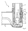
- Figure 1, in a vertical section, shows a vertically aligned holding part, upon which a mounting part having a horizontal arm is supported via a securing ring, and wherein a screw head of a screw, screwed into the holding part, can be moved in a groove cut into the mounting part when the arm is swiveled;
- Figure 2, in a vertical section, shows the object of Figure 1, however, with a failed securing ring, a piece on the holding part with the mounting part slipping downwards together with the arm, and with a screw head impacting the upper, horizontally aligned surface of the groove, with said head being part of a securing mechanism, as well as
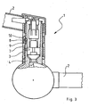
- Figure 3, in a vertical section, shows another mounting part on another holding part, wherein a screw is also provided for securing the mounting part on the holding part, however, the screw is screwed-in in the mounting part, and the screw head projects into a groove of the holding part.
- With a
fixture 1 with aswiveling arm 2 of a support system to mount a medical device, aholding part 3 with a ceiling mount and amounting part 4 are rotatably connected to the holding part 3 (Figure 1). The (not shown) device places a load on themounting part 4 and thus theholding part 3. Asecuring mechanism 5 is used to secure themounting part 4 on theholding part 3. Thesecuring mechanism 5 has ascrew 7 with ascrew head 8. Thescrew 7 engages with theinner thread 13 of theholding part 3 and, in this manner, is screwed into themounting part 4. The screw head 8 projects into agroove 9 of a bushing 14 of themounting part 4. Thescrew head 8 can therefore move freely in thegroove 9 when themounting part 4 is rotated around theholding part 3. Thegroove 9 is bordered by a horizontally alignedsurface 6. Aslot 10 is used to insert thescrew 7. - Acting as a connection between the
holding part 3 and the mountingpart 4, asecuring ring 11 in aholder 12 of theholding part 3, upon which thebushing 14 of the mountingpart 4 and therefore the mountingpart 4 together with thearm 2 are supported, is provided. - If the
securing ring 11 fails after thefixture 1 has been used for a long period of time, and it falls out (Figure 2), then the mounting part along with thearm 2 slips downwards a few millimeters along theholding part 3. However, this does not result in themounting part 4 coming loose from theholding part 3, because thescrew 7, as a part of thesecuring mechanism 5, prevents this. Thus, thesurface 6 impacts thescrew head 8 during this slippage downwards. Said screw head has a line-shaped, wedge-typetapered edge 15, which digs into thesurface 6 or places itself between thesurface 6 and theholding part 3. This results in difficulty of movement when the arm is rotated whereby the occurred damage is noticed. - The art is similar in the second embodiment example (Figure 3). The holding
part 3 and themounting part 4, however, connect twoarms 2, which are linked together with a joint, with each arm swiveling in a horizontal plane. Contrary to the first embodiment example, thescrew 7 is screwed into themounting part 4, and thescrew head 8 can be moved in agroove 9 of theholding part 3. Should the connection between theholding part 3 and themounting part 4 become loose, thescrew 7 secures thefixture 1 precisely as described in the first embodiment example. - 1
- Fixture
- 2
- Arm
- 3
- Holding part
- 4
- Mounting part
- 5
- Securing mechanism
- 6
- Surface
- 7
- Screw
- 8
- Screw head
- 9
- Groove
- 10
- Slot
- 11
- Securing ring
- 12
- Holder
- 13
- Inner thread
- 14
- Bushing
- 15
- Edge
Claims (4)
- A fixture (1), particularly with a swiveling arm (2), for a support system to secure, in particular, a medical or salon-technical device, with a holding part (3) and a mounting part (4) mounted on the holding part (3), wherein the holding part (3) is connected to a stationary support, in particular, a ceiling mount or a wall mount, the mounting part (4) is rotatably connected to the holding part (3), the device places a load on the mounting part (4) and therefore the holding part (3), a securing mechanism (5) is provided to secure the mounting part (4) with respect to the holding part (3), the securing mechanism (5) has a screw (7) with a screw head (8), and the screw (7) extends into the holding part (3), wherein the screw (7) is screwed into the holding part (3) or the mounting part (4), and wherein the screw head (8) projects into a groove (9) of a bushing (14) of the other part (3, 4), i.e. of the mounting part (4) or of the holding part (3), and wherein the screw head (8) can move freely in the groove (9) when there is a relative rotation between the holding part (3) and the mounting part (4), and wherein the groove (9) is bordered by an upper surface (6).
- Fixture as recited in Claim 1, wherein a securing ring (11) is provided in a holder (12) of the holding part (3) upon which the bushing (14) of the mounting part (4) is supported.
- Fixture as recited in Claim 1, wherein the screw head (8) has a wedge-shaped edge (15).
- Fixture as recited in Claim 1, Claim 2, or Claim 3, wherein a slot (10) bordering the groove (9) is provided for inserting the screw (7) into an inner thread (13) and for tightening.
Priority Applications (9)
| Application Number | Priority Date | Filing Date | Title |
|---|---|---|---|
| PT06000550T PT1808634E (en) | 2006-01-12 | 2006-01-12 | Fixture to mount a device |
| ES06000550T ES2317346T3 (en) | 2006-01-12 | 2006-01-12 | CLAMPING DEVICE FOR MOUNTING AN APPLIANCE. |
| DE602006003403T DE602006003403D1 (en) | 2006-01-12 | 2006-01-12 | Holding device for mounting a device |
| EP06000550A EP1808634B1 (en) | 2006-01-12 | 2006-01-12 | Fixture to mount a device |
| AT06000550T ATE412847T1 (en) | 2006-01-12 | 2006-01-12 | HOLDING DEVICE FOR MOUNTING A DEVICE |
| PL06000550T PL1808634T3 (en) | 2006-01-12 | 2006-01-12 | Fixture to mount a device |
| US11/652,851 US20070215771A1 (en) | 2006-01-12 | 2007-01-12 | Fixture to mount a device |
| PCT/IB2007/050099 WO2007080551A2 (en) | 2006-01-12 | 2007-01-12 | Fixture to mount a device |
| HK07113894.3A HK1108935B (en) | 2007-12-19 | Fixture to mount a device |
Applications Claiming Priority (1)
| Application Number | Priority Date | Filing Date | Title |
|---|---|---|---|
| EP06000550A EP1808634B1 (en) | 2006-01-12 | 2006-01-12 | Fixture to mount a device |
Publications (2)
| Publication Number | Publication Date |
|---|---|
| EP1808634A1 true EP1808634A1 (en) | 2007-07-18 |
| EP1808634B1 EP1808634B1 (en) | 2008-10-29 |
Family
ID=36593001
Family Applications (1)
| Application Number | Title | Priority Date | Filing Date |
|---|---|---|---|
| EP06000550A Expired - Lifetime EP1808634B1 (en) | 2006-01-12 | 2006-01-12 | Fixture to mount a device |
Country Status (8)
| Country | Link |
|---|---|
| US (1) | US20070215771A1 (en) |
| EP (1) | EP1808634B1 (en) |
| AT (1) | ATE412847T1 (en) |
| DE (1) | DE602006003403D1 (en) |
| ES (1) | ES2317346T3 (en) |
| PL (1) | PL1808634T3 (en) |
| PT (1) | PT1808634E (en) |
| WO (1) | WO2007080551A2 (en) |
Cited By (1)
| Publication number | Priority date | Publication date | Assignee | Title |
|---|---|---|---|---|
| US20220154753A1 (en) * | 2020-11-13 | 2022-05-19 | Mavig Gmbh | Device, system and method for locking a connection element |
Families Citing this family (2)
| Publication number | Priority date | Publication date | Assignee | Title |
|---|---|---|---|---|
| GB0620259D0 (en) * | 2006-10-12 | 2006-11-22 | Astex Therapeutics Ltd | Pharmaceutical compounds |
| US12612997B2 (en) * | 2023-03-02 | 2026-04-28 | Smithfield Foods, Inc. | Food processing tree support |
Citations (6)
| Publication number | Priority date | Publication date | Assignee | Title |
|---|---|---|---|---|
| US3168341A (en) * | 1963-12-12 | 1965-02-02 | Lucien J J Beaudet | Spring clip retainer |
| US3913880A (en) * | 1974-03-28 | 1975-10-21 | Joseph A Lucasey | Support stand for an appliance |
| US4159093A (en) * | 1978-05-26 | 1979-06-26 | American Optical Corporation | Adjustable support for a headrest |
| DE4321726A1 (en) * | 1993-06-30 | 1995-01-12 | Wella Ag | Device for fastening an appliance on a retaining element |
| DE29905420U1 (en) * | 1999-03-29 | 1999-07-08 | Schwering | Holder for one device |
| EP1283969A1 (en) | 2000-05-25 | 2003-02-19 | Mavig GmbH | Extension arm |
Family Cites Families (19)
| Publication number | Priority date | Publication date | Assignee | Title |
|---|---|---|---|---|
| US1682180A (en) * | 1928-08-28 | Eael s | ||
| US669378A (en) * | 1900-02-21 | 1901-03-05 | Wilbur Rice Baldwin | Bedstead attachment. |
| US866658A (en) * | 1907-06-03 | 1907-09-24 | Camilla J Johnsen | Window-reflector. |
| US3306639A (en) * | 1964-10-02 | 1967-02-28 | Chester S Lyon | Extensible torque rod |
| US3366430A (en) * | 1966-06-21 | 1968-01-30 | William R. Diedrich | Support tray assembly |
| US4050661A (en) * | 1975-05-05 | 1977-09-27 | James Neill Holdings Limited | Adjustable mounting |
| US4030691A (en) * | 1976-07-16 | 1977-06-21 | Fleshman John F | Night fishing rig |
| US4270721A (en) * | 1978-09-22 | 1981-06-02 | Mainor Jr Ross F | Instrument support |
| JPS57144399A (en) * | 1981-02-27 | 1982-09-06 | Mitsutoyo Seisakusho | Joint type stand for utility equipment |
| US4880193A (en) * | 1986-11-14 | 1989-11-14 | Jerome Warshawsky | Less than 360 degree lamp swivel |
| US4913393A (en) * | 1987-03-09 | 1990-04-03 | Wood Charles F | Mounting for attachments to a wheelchair, a geriatric chair and the like |
| US4911146A (en) * | 1989-09-07 | 1990-03-27 | Ironsmith, Inc. | Device for fireplace cooking |
| US5039043A (en) * | 1990-04-05 | 1991-08-13 | Hodge Robert B | Post holder |
| US5655741A (en) * | 1995-03-16 | 1997-08-12 | Liebel-Flarsheim Company | Pivotal instrument support apparatus |
| US5772174A (en) * | 1995-11-22 | 1998-06-30 | Hirsch; Steven | Adjustable stand for mounting on a wall or the like |
| US5909864A (en) * | 1998-03-25 | 1999-06-08 | Camel Furniture Co., Ltd. | Chair-mount adjustable keyboard supporting assembly |
| US6905101B1 (en) * | 2002-06-11 | 2005-06-14 | Chief Manufacturing Inc. | Adjustable, self-balancing flat panel display mounting system |
| US7380760B2 (en) * | 2003-05-30 | 2008-06-03 | Csav, Inc. | Self-balancing adjustable mounting system with friction adjustment |
| US7063296B2 (en) * | 2003-06-13 | 2006-06-20 | Innovative Office Products, Inc. | Rail mounting apparatus for electronic device |
-
2006
- 2006-01-12 PT PT06000550T patent/PT1808634E/en unknown
- 2006-01-12 PL PL06000550T patent/PL1808634T3/en unknown
- 2006-01-12 ES ES06000550T patent/ES2317346T3/en not_active Expired - Lifetime
- 2006-01-12 DE DE602006003403T patent/DE602006003403D1/en not_active Expired - Lifetime
- 2006-01-12 AT AT06000550T patent/ATE412847T1/en not_active IP Right Cessation
- 2006-01-12 EP EP06000550A patent/EP1808634B1/en not_active Expired - Lifetime
-
2007
- 2007-01-12 WO PCT/IB2007/050099 patent/WO2007080551A2/en not_active Ceased
- 2007-01-12 US US11/652,851 patent/US20070215771A1/en not_active Abandoned
Patent Citations (6)
| Publication number | Priority date | Publication date | Assignee | Title |
|---|---|---|---|---|
| US3168341A (en) * | 1963-12-12 | 1965-02-02 | Lucien J J Beaudet | Spring clip retainer |
| US3913880A (en) * | 1974-03-28 | 1975-10-21 | Joseph A Lucasey | Support stand for an appliance |
| US4159093A (en) * | 1978-05-26 | 1979-06-26 | American Optical Corporation | Adjustable support for a headrest |
| DE4321726A1 (en) * | 1993-06-30 | 1995-01-12 | Wella Ag | Device for fastening an appliance on a retaining element |
| DE29905420U1 (en) * | 1999-03-29 | 1999-07-08 | Schwering | Holder for one device |
| EP1283969A1 (en) | 2000-05-25 | 2003-02-19 | Mavig GmbH | Extension arm |
Cited By (3)
| Publication number | Priority date | Publication date | Assignee | Title |
|---|---|---|---|---|
| US20220154753A1 (en) * | 2020-11-13 | 2022-05-19 | Mavig Gmbh | Device, system and method for locking a connection element |
| DE102020214296A1 (en) | 2020-11-13 | 2022-05-19 | Mavig Gmbh | Device, system and method for locking a connecting element |
| US12680566B2 (en) * | 2020-11-13 | 2026-07-14 | Mavig Gmbh | Device, system and method for locking a connection element |
Also Published As
| Publication number | Publication date |
|---|---|
| ES2317346T3 (en) | 2009-04-16 |
| WO2007080551A3 (en) | 2007-11-15 |
| US20070215771A1 (en) | 2007-09-20 |
| WO2007080551A2 (en) | 2007-07-19 |
| PT1808634E (en) | 2008-12-11 |
| PL1808634T3 (en) | 2009-04-30 |
| EP1808634B1 (en) | 2008-10-29 |
| ATE412847T1 (en) | 2008-11-15 |
| DE602006003403D1 (en) | 2008-12-11 |
| HK1108935A1 (en) | 2008-05-23 |
Similar Documents
| Publication | Publication Date | Title |
|---|---|---|
| US6779767B2 (en) | Extension arm | |
| CN101925770A (en) | Universal structural attachment for seismic struts | |
| EP1852560A3 (en) | Mount interface for suspended ceiling | |
| JP2015034633A (en) | Stationary portion structure for vibration preventing metal fitting | |
| US7780132B1 (en) | Construction hanger | |
| EP1808634B1 (en) | Fixture to mount a device | |
| EP1972737A3 (en) | Scaffold arrangement | |
| CA2737327C (en) | Hand rail mounting bracket for an electrical panel | |
| HK1108935B (en) | Fixture to mount a device | |
| AU2011353162A1 (en) | Attachment means, light fittings, use of a roller-type spring and a method for mounting of light fittings | |
| US11079061B1 (en) | Gravity actuated clamp | |
| CA3184049A1 (en) | Rack rail support | |
| CN223976156U (en) | Auxiliary device for air conditioner installation | |
| JP3183550U (en) | Scaffolding fixture | |
| CN210640646U (en) | Cable hook | |
| CN114892944B (en) | Temporary fixing device for shaft steel frame | |
| CN221696038U (en) | Penetrating type pre-clamping mechanism | |
| CN214948042U (en) | A supervisory equipment mount pad for unevenness wall | |
| KR20230078103A (en) | A supporting device having multi joints | |
| CN217235057U (en) | Electronic equipment support | |
| JP2015183507A (en) | Brace upper part installing metal fitting | |
| KR20100033138A (en) | Fixing device of hose reel | |
| CN106535553B (en) | A server slide rail with quick installation function | |
| CN219828469U (en) | Hanging assembly and display device | |
| CN220762335U (en) | Special fixture for computer motherboard |
Legal Events
| Date | Code | Title | Description |
|---|---|---|---|
| PUAI | Public reference made under article 153(3) epc to a published international application that has entered the european phase |
Free format text: ORIGINAL CODE: 0009012 |
|
| 17P | Request for examination filed |
Effective date: 20060112 |
|
| AK | Designated contracting states |
Kind code of ref document: A1 Designated state(s): AT BE BG CH CY CZ DE DK EE ES FI FR GB GR HU IE IS IT LI LT LU LV MC NL PL PT RO SE SI SK TR |
|
| AX | Request for extension of the european patent |
Extension state: AL BA HR MK YU |
|
| 17Q | First examination report despatched |
Effective date: 20070928 |
|
| R17C | First examination report despatched (corrected) |
Effective date: 20071030 |
|
| RAP1 | Party data changed (applicant data changed or rights of an application transferred) |
Owner name: ONDAL HOLDING GMBH |
|
| AKX | Designation fees paid |
Designated state(s): AT BE BG CH CY CZ DE DK EE ES FI FR GB GR HU IE IS IT LI LT LU LV MC NL PL PT RO SE SI SK TR |
|
| GRAP | Despatch of communication of intention to grant a patent |
Free format text: ORIGINAL CODE: EPIDOSNIGR1 |
|
| REG | Reference to a national code |
Ref country code: HK Ref legal event code: DE Ref document number: 1108935 Country of ref document: HK |
|
| GRAS | Grant fee paid |
Free format text: ORIGINAL CODE: EPIDOSNIGR3 |
|
| GRAA | (expected) grant |
Free format text: ORIGINAL CODE: 0009210 |
|
| AK | Designated contracting states |
Kind code of ref document: B1 Designated state(s): AT BE BG CH CY CZ DE DK EE ES FI FR GB GR HU IE IS IT LI LT LU LV MC NL PL PT RO SE SI SK TR |
|
| REG | Reference to a national code |
Ref country code: GB Ref legal event code: FG4D |
|
| REG | Reference to a national code |
Ref country code: CH Ref legal event code: EP |
|
| REG | Reference to a national code |
Ref country code: IE Ref legal event code: FG4D |
|
| REF | Corresponds to: |
Ref document number: 602006003403 Country of ref document: DE Date of ref document: 20081211 Kind code of ref document: P |
|
| REG | Reference to a national code |
Ref country code: PT Ref legal event code: SC4A Free format text: AVAILABILITY OF NATIONAL TRANSLATION Effective date: 20081126 |
|
| REG | Reference to a national code |
Ref country code: SE Ref legal event code: TRGR |
|
| REG | Reference to a national code |
Ref country code: GR Ref legal event code: EP Ref document number: 20090400094 Country of ref document: GR |
|
| PGFP | Annual fee paid to national office [announced via postgrant information from national office to epo] |
Ref country code: PT Payment date: 20081203 Year of fee payment: 4 |
|
| NLV1 | Nl: lapsed or annulled due to failure to fulfill the requirements of art. 29p and 29m of the patents act | ||
| REG | Reference to a national code |
Ref country code: ES Ref legal event code: FG2A Ref document number: 2317346 Country of ref document: ES Kind code of ref document: T3 |
|
| LTIE | Lt: invalidation of european patent or patent extension |
Effective date: 20081029 |
|
| PG25 | Lapsed in a contracting state [announced via postgrant information from national office to epo] |
Ref country code: LT Free format text: LAPSE BECAUSE OF FAILURE TO SUBMIT A TRANSLATION OF THE DESCRIPTION OR TO PAY THE FEE WITHIN THE PRESCRIBED TIME-LIMIT Effective date: 20081029 Ref country code: BG Free format text: LAPSE BECAUSE OF FAILURE TO SUBMIT A TRANSLATION OF THE DESCRIPTION OR TO PAY THE FEE WITHIN THE PRESCRIBED TIME-LIMIT Effective date: 20090129 |
|
| PGFP | Annual fee paid to national office [announced via postgrant information from national office to epo] |
Ref country code: IE Payment date: 20090122 Year of fee payment: 4 Ref country code: HU Payment date: 20090108 Year of fee payment: 4 Ref country code: ES Payment date: 20090126 Year of fee payment: 4 Ref country code: AT Payment date: 20090122 Year of fee payment: 4 |
|
| REG | Reference to a national code |
Ref country code: PL Ref legal event code: T3 |
|
| REG | Reference to a national code |
Ref country code: HU Ref legal event code: AG4A Ref document number: E004866 Country of ref document: HU |
|
| PG25 | Lapsed in a contracting state [announced via postgrant information from national office to epo] |
Ref country code: SI Free format text: LAPSE BECAUSE OF FAILURE TO SUBMIT A TRANSLATION OF THE DESCRIPTION OR TO PAY THE FEE WITHIN THE PRESCRIBED TIME-LIMIT Effective date: 20081029 Ref country code: NL Free format text: LAPSE BECAUSE OF FAILURE TO SUBMIT A TRANSLATION OF THE DESCRIPTION OR TO PAY THE FEE WITHIN THE PRESCRIBED TIME-LIMIT Effective date: 20081029 Ref country code: LV Free format text: LAPSE BECAUSE OF FAILURE TO SUBMIT A TRANSLATION OF THE DESCRIPTION OR TO PAY THE FEE WITHIN THE PRESCRIBED TIME-LIMIT Effective date: 20081029 Ref country code: IS Free format text: LAPSE BECAUSE OF FAILURE TO SUBMIT A TRANSLATION OF THE DESCRIPTION OR TO PAY THE FEE WITHIN THE PRESCRIBED TIME-LIMIT Effective date: 20090228 |
|
| PGFP | Annual fee paid to national office [announced via postgrant information from national office to epo] |
Ref country code: PL Payment date: 20090109 Year of fee payment: 4 Ref country code: FI Payment date: 20090122 Year of fee payment: 4 Ref country code: CZ Payment date: 20090107 Year of fee payment: 4 |
|
| REG | Reference to a national code |
Ref country code: HK Ref legal event code: GR Ref document number: 1108935 Country of ref document: HK |
|
| PG25 | Lapsed in a contracting state [announced via postgrant information from national office to epo] |
Ref country code: RO Free format text: LAPSE BECAUSE OF FAILURE TO SUBMIT A TRANSLATION OF THE DESCRIPTION OR TO PAY THE FEE WITHIN THE PRESCRIBED TIME-LIMIT Effective date: 20081029 Ref country code: EE Free format text: LAPSE BECAUSE OF FAILURE TO SUBMIT A TRANSLATION OF THE DESCRIPTION OR TO PAY THE FEE WITHIN THE PRESCRIBED TIME-LIMIT Effective date: 20081029 Ref country code: DK Free format text: LAPSE BECAUSE OF FAILURE TO SUBMIT A TRANSLATION OF THE DESCRIPTION OR TO PAY THE FEE WITHIN THE PRESCRIBED TIME-LIMIT Effective date: 20081029 |
|
| PGFP | Annual fee paid to national office [announced via postgrant information from national office to epo] |
Ref country code: BE Payment date: 20090129 Year of fee payment: 4 |
|
| PG25 | Lapsed in a contracting state [announced via postgrant information from national office to epo] |
Ref country code: MC Free format text: LAPSE BECAUSE OF NON-PAYMENT OF DUE FEES Effective date: 20090131 |
|
| PGFP | Annual fee paid to national office [announced via postgrant information from national office to epo] |
Ref country code: SE Payment date: 20090126 Year of fee payment: 4 |
|
| PLBE | No opposition filed within time limit |
Free format text: ORIGINAL CODE: 0009261 |
|
| STAA | Information on the status of an ep patent application or granted ep patent |
Free format text: STATUS: NO OPPOSITION FILED WITHIN TIME LIMIT |
|
| PGFP | Annual fee paid to national office [announced via postgrant information from national office to epo] |
Ref country code: SK Payment date: 20090105 Year of fee payment: 4 |
|
| 26N | No opposition filed |
Effective date: 20090730 |
|
| PGFP | Annual fee paid to national office [announced via postgrant information from national office to epo] |
Ref country code: IT Payment date: 20090131 Year of fee payment: 4 Ref country code: FR Payment date: 20090120 Year of fee payment: 4 |
|
| REG | Reference to a national code |
Ref country code: PT Ref legal event code: MM4A Free format text: LAPSE DUE TO NON-PAYMENT OF FEES Effective date: 20100712 |
|
| BERE | Be: lapsed |
Owner name: ONDAL HOLDING G.M.B.H. Effective date: 20100131 |
|
| REG | Reference to a national code |
Ref country code: CH Ref legal event code: PL |
|
| GBPC | Gb: european patent ceased through non-payment of renewal fee |
Effective date: 20100112 |
|
| EUG | Se: european patent has lapsed | ||
| REG | Reference to a national code |
Ref country code: SK Ref legal event code: MM4A Ref document number: E 4964 Country of ref document: SK Effective date: 20100112 |
|
| REG | Reference to a national code |
Ref country code: FR Ref legal event code: ST Effective date: 20100930 |
|
| REG | Reference to a national code |
Ref country code: IE Ref legal event code: MM4A |
|
| PG25 | Lapsed in a contracting state [announced via postgrant information from national office to epo] |
Ref country code: LI Free format text: LAPSE BECAUSE OF NON-PAYMENT OF DUE FEES Effective date: 20100131 Ref country code: HU Free format text: LAPSE BECAUSE OF NON-PAYMENT OF DUE FEES Effective date: 20100113 Ref country code: FR Free format text: LAPSE BECAUSE OF NON-PAYMENT OF DUE FEES Effective date: 20100201 Ref country code: CH Free format text: LAPSE BECAUSE OF NON-PAYMENT OF DUE FEES Effective date: 20100131 |
|
| PG25 | Lapsed in a contracting state [announced via postgrant information from national office to epo] |
Ref country code: SK Free format text: LAPSE BECAUSE OF NON-PAYMENT OF DUE FEES Effective date: 20100112 Ref country code: FI Free format text: LAPSE BECAUSE OF NON-PAYMENT OF DUE FEES Effective date: 20100112 Ref country code: CZ Free format text: LAPSE BECAUSE OF NON-PAYMENT OF DUE FEES Effective date: 20100112 |
|
| PG25 | Lapsed in a contracting state [announced via postgrant information from national office to epo] |
Ref country code: GB Free format text: LAPSE BECAUSE OF NON-PAYMENT OF DUE FEES Effective date: 20100112 |
|
| PG25 | Lapsed in a contracting state [announced via postgrant information from national office to epo] |
Ref country code: PT Free format text: LAPSE BECAUSE OF NON-PAYMENT OF DUE FEES Effective date: 20100712 Ref country code: IE Free format text: LAPSE BECAUSE OF NON-PAYMENT OF DUE FEES Effective date: 20100112 |
|
| PG25 | Lapsed in a contracting state [announced via postgrant information from national office to epo] |
Ref country code: BE Free format text: LAPSE BECAUSE OF NON-PAYMENT OF DUE FEES Effective date: 20100131 |
|
| REG | Reference to a national code |
Ref country code: ES Ref legal event code: FD2A Effective date: 20110225 |
|
| PG25 | Lapsed in a contracting state [announced via postgrant information from national office to epo] |
Ref country code: IT Free format text: LAPSE BECAUSE OF NON-PAYMENT OF DUE FEES Effective date: 20100112 |
|
| PG25 | Lapsed in a contracting state [announced via postgrant information from national office to epo] |
Ref country code: LU Free format text: LAPSE BECAUSE OF NON-PAYMENT OF DUE FEES Effective date: 20090112 |
|
| PG25 | Lapsed in a contracting state [announced via postgrant information from national office to epo] |
Ref country code: ES Free format text: LAPSE BECAUSE OF NON-PAYMENT OF DUE FEES Effective date: 20110224 |
|
| PG25 | Lapsed in a contracting state [announced via postgrant information from national office to epo] |
Ref country code: CY Free format text: LAPSE BECAUSE OF FAILURE TO SUBMIT A TRANSLATION OF THE DESCRIPTION OR TO PAY THE FEE WITHIN THE PRESCRIBED TIME-LIMIT Effective date: 20081029 Ref country code: ES Free format text: LAPSE BECAUSE OF NON-PAYMENT OF DUE FEES Effective date: 20100113 |
|
| PGFP | Annual fee paid to national office [announced via postgrant information from national office to epo] |
Ref country code: TR Payment date: 20081231 Year of fee payment: 4 |
|
| PG25 | Lapsed in a contracting state [announced via postgrant information from national office to epo] |
Ref country code: AT Free format text: LAPSE BECAUSE OF NON-PAYMENT OF DUE FEES Effective date: 20110112 |
|
| REG | Reference to a national code |
Ref country code: PL Ref legal event code: LAPE |
|
| PG25 | Lapsed in a contracting state [announced via postgrant information from national office to epo] |
Ref country code: PL Free format text: LAPSE BECAUSE OF NON-PAYMENT OF DUE FEES Effective date: 20100112 |
|
| PG25 | Lapsed in a contracting state [announced via postgrant information from national office to epo] |
Ref country code: SE Free format text: LAPSE BECAUSE OF NON-PAYMENT OF DUE FEES Effective date: 20100113 |
|
| PG25 | Lapsed in a contracting state [announced via postgrant information from national office to epo] |
Ref country code: TR Free format text: LAPSE BECAUSE OF NON-PAYMENT OF DUE FEES Effective date: 20100112 |
|
| PGFP | Annual fee paid to national office [announced via postgrant information from national office to epo] |
Ref country code: DE Payment date: 20191121 Year of fee payment: 15 |
|
| REG | Reference to a national code |
Ref country code: DE Ref legal event code: R119 Ref document number: 602006003403 Country of ref document: DE |
|
| PG25 | Lapsed in a contracting state [announced via postgrant information from national office to epo] |
Ref country code: DE Free format text: LAPSE BECAUSE OF NON-PAYMENT OF DUE FEES Effective date: 20210803 |