EP1808585A2 - Vehicle - Google Patents
Vehicle Download PDFInfo
- Publication number
- EP1808585A2 EP1808585A2 EP07000877A EP07000877A EP1808585A2 EP 1808585 A2 EP1808585 A2 EP 1808585A2 EP 07000877 A EP07000877 A EP 07000877A EP 07000877 A EP07000877 A EP 07000877A EP 1808585 A2 EP1808585 A2 EP 1808585A2
- Authority
- EP
- European Patent Office
- Prior art keywords
- funnel
- moveable
- link
- opening
- case
- Prior art date
- Legal status (The legal status is an assumption and is not a legal conclusion. Google has not performed a legal analysis and makes no representation as to the accuracy of the status listed.)
- Granted
Links
Images


Classifications
-
- F—MECHANICAL ENGINEERING; LIGHTING; HEATING; WEAPONS; BLASTING
- F02—COMBUSTION ENGINES; HOT-GAS OR COMBUSTION-PRODUCT ENGINE PLANTS
- F02B—INTERNAL-COMBUSTION PISTON ENGINES; COMBUSTION ENGINES IN GENERAL
- F02B27/00—Use of kinetic or wave energy of charge in induction systems, or of combustion residues in exhaust systems, for improving quantity of charge or for increasing removal of combustion residues
- F02B27/02—Use of kinetic or wave energy of charge in induction systems, or of combustion residues in exhaust systems, for improving quantity of charge or for increasing removal of combustion residues the systems having variable, i.e. adjustable, cross-sectional areas, chambers of variable volume, or like variable means
- F02B27/0294—Actuators or controllers therefor; Diagnosis; Calibration
-
- F—MECHANICAL ENGINEERING; LIGHTING; HEATING; WEAPONS; BLASTING
- F02—COMBUSTION ENGINES; HOT-GAS OR COMBUSTION-PRODUCT ENGINE PLANTS
- F02B—INTERNAL-COMBUSTION PISTON ENGINES; COMBUSTION ENGINES IN GENERAL
- F02B27/00—Use of kinetic or wave energy of charge in induction systems, or of combustion residues in exhaust systems, for improving quantity of charge or for increasing removal of combustion residues
- F02B27/02—Use of kinetic or wave energy of charge in induction systems, or of combustion residues in exhaust systems, for improving quantity of charge or for increasing removal of combustion residues the systems having variable, i.e. adjustable, cross-sectional areas, chambers of variable volume, or like variable means
- F02B27/0205—Use of kinetic or wave energy of charge in induction systems, or of combustion residues in exhaust systems, for improving quantity of charge or for increasing removal of combustion residues the systems having variable, i.e. adjustable, cross-sectional areas, chambers of variable volume, or like variable means characterised by the charging effect
- F02B27/0215—Oscillating pipe charging, i.e. variable intake pipe length charging
-
- F—MECHANICAL ENGINEERING; LIGHTING; HEATING; WEAPONS; BLASTING
- F02—COMBUSTION ENGINES; HOT-GAS OR COMBUSTION-PRODUCT ENGINE PLANTS
- F02B—INTERNAL-COMBUSTION PISTON ENGINES; COMBUSTION ENGINES IN GENERAL
- F02B27/00—Use of kinetic or wave energy of charge in induction systems, or of combustion residues in exhaust systems, for improving quantity of charge or for increasing removal of combustion residues
- F02B27/02—Use of kinetic or wave energy of charge in induction systems, or of combustion residues in exhaust systems, for improving quantity of charge or for increasing removal of combustion residues the systems having variable, i.e. adjustable, cross-sectional areas, chambers of variable volume, or like variable means
- F02B27/0226—Use of kinetic or wave energy of charge in induction systems, or of combustion residues in exhaust systems, for improving quantity of charge or for increasing removal of combustion residues the systems having variable, i.e. adjustable, cross-sectional areas, chambers of variable volume, or like variable means characterised by the means generating the charging effect
- F02B27/0231—Movable ducts, walls or the like
-
- F—MECHANICAL ENGINEERING; LIGHTING; HEATING; WEAPONS; BLASTING
- F02—COMBUSTION ENGINES; HOT-GAS OR COMBUSTION-PRODUCT ENGINE PLANTS
- F02M—SUPPLYING COMBUSTION ENGINES IN GENERAL WITH COMBUSTIBLE MIXTURES OR CONSTITUENTS THEREOF
- F02M35/00—Combustion-air cleaners, air intakes, intake silencers, or induction systems specially adapted for, or arranged on, internal-combustion engines
- F02M35/10—Air intakes; Induction systems
- F02M35/10006—Air intakes; Induction systems characterised by the position of elements of the air intake system in direction of the air intake flow, i.e. between ambient air inlet and supply to the combustion chamber
- F02M35/10026—Plenum chambers
- F02M35/10039—Intake ducts situated partly within or on the plenum chamber housing
-
- F—MECHANICAL ENGINEERING; LIGHTING; HEATING; WEAPONS; BLASTING
- F02—COMBUSTION ENGINES; HOT-GAS OR COMBUSTION-PRODUCT ENGINE PLANTS
- F02M—SUPPLYING COMBUSTION ENGINES IN GENERAL WITH COMBUSTIBLE MIXTURES OR CONSTITUENTS THEREOF
- F02M35/00—Combustion-air cleaners, air intakes, intake silencers, or induction systems specially adapted for, or arranged on, internal-combustion engines
- F02M35/10—Air intakes; Induction systems
- F02M35/10006—Air intakes; Induction systems characterised by the position of elements of the air intake system in direction of the air intake flow, i.e. between ambient air inlet and supply to the combustion chamber
- F02M35/10026—Plenum chambers
- F02M35/10052—Plenum chambers special shapes or arrangements of plenum chambers; Constructional details
-
- F—MECHANICAL ENGINEERING; LIGHTING; HEATING; WEAPONS; BLASTING
- F02—COMBUSTION ENGINES; HOT-GAS OR COMBUSTION-PRODUCT ENGINE PLANTS
- F02M—SUPPLYING COMBUSTION ENGINES IN GENERAL WITH COMBUSTIBLE MIXTURES OR CONSTITUENTS THEREOF
- F02M35/00—Combustion-air cleaners, air intakes, intake silencers, or induction systems specially adapted for, or arranged on, internal-combustion engines
- F02M35/10—Air intakes; Induction systems
- F02M35/10091—Air intakes; Induction systems characterised by details of intake ducts: shapes; connections; arrangements
- F02M35/10104—Substantially vertically arranged ducts
-
- F—MECHANICAL ENGINEERING; LIGHTING; HEATING; WEAPONS; BLASTING
- F02—COMBUSTION ENGINES; HOT-GAS OR COMBUSTION-PRODUCT ENGINE PLANTS
- F02M—SUPPLYING COMBUSTION ENGINES IN GENERAL WITH COMBUSTIBLE MIXTURES OR CONSTITUENTS THEREOF
- F02M35/00—Combustion-air cleaners, air intakes, intake silencers, or induction systems specially adapted for, or arranged on, internal-combustion engines
- F02M35/16—Combustion-air cleaners, air intakes, intake silencers, or induction systems specially adapted for, or arranged on, internal-combustion engines characterised by use in vehicles
- F02M35/162—Motorcycles; All-terrain vehicles, e.g. quads, snowmobiles; Small vehicles, e.g. forklifts
-
- F—MECHANICAL ENGINEERING; LIGHTING; HEATING; WEAPONS; BLASTING
- F02—COMBUSTION ENGINES; HOT-GAS OR COMBUSTION-PRODUCT ENGINE PLANTS
- F02B—INTERNAL-COMBUSTION PISTON ENGINES; COMBUSTION ENGINES IN GENERAL
- F02B61/00—Adaptations of engines for driving vehicles or for driving propellers; Combinations of engines with gearing
- F02B61/02—Adaptations of engines for driving vehicles or for driving propellers; Combinations of engines with gearing for driving cycles
-
- F—MECHANICAL ENGINEERING; LIGHTING; HEATING; WEAPONS; BLASTING
- F02—COMBUSTION ENGINES; HOT-GAS OR COMBUSTION-PRODUCT ENGINE PLANTS
- F02M—SUPPLYING COMBUSTION ENGINES IN GENERAL WITH COMBUSTIBLE MIXTURES OR CONSTITUENTS THEREOF
- F02M35/00—Combustion-air cleaners, air intakes, intake silencers, or induction systems specially adapted for, or arranged on, internal-combustion engines
- F02M35/02—Air cleaners
- F02M35/024—Air cleaners using filters, e.g. moistened
- F02M35/02475—Air cleaners using filters, e.g. moistened characterised by the shape of the filter element
- F02M35/02491—Flat filter elements, e.g. rectangular
-
- F—MECHANICAL ENGINEERING; LIGHTING; HEATING; WEAPONS; BLASTING
- F02—COMBUSTION ENGINES; HOT-GAS OR COMBUSTION-PRODUCT ENGINE PLANTS
- F02M—SUPPLYING COMBUSTION ENGINES IN GENERAL WITH COMBUSTIBLE MIXTURES OR CONSTITUENTS THEREOF
- F02M35/00—Combustion-air cleaners, air intakes, intake silencers, or induction systems specially adapted for, or arranged on, internal-combustion engines
- F02M35/10—Air intakes; Induction systems
- F02M35/10209—Fluid connections to the air intake system; their arrangement of pipes, valves or the like
- F02M35/10216—Fuel injectors; Fuel pipes or rails; Fuel pumps or pressure regulators
-
- F—MECHANICAL ENGINEERING; LIGHTING; HEATING; WEAPONS; BLASTING
- F02—COMBUSTION ENGINES; HOT-GAS OR COMBUSTION-PRODUCT ENGINE PLANTS
- F02M—SUPPLYING COMBUSTION ENGINES IN GENERAL WITH COMBUSTIBLE MIXTURES OR CONSTITUENTS THEREOF
- F02M35/00—Combustion-air cleaners, air intakes, intake silencers, or induction systems specially adapted for, or arranged on, internal-combustion engines
- F02M35/10—Air intakes; Induction systems
- F02M35/10242—Devices or means connected to or integrated into air intakes; Air intakes combined with other engine or vehicle parts
- F02M35/10301—Flexible, resilient, pivotally or movable parts; Membranes
-
- Y—GENERAL TAGGING OF NEW TECHNOLOGICAL DEVELOPMENTS; GENERAL TAGGING OF CROSS-SECTIONAL TECHNOLOGIES SPANNING OVER SEVERAL SECTIONS OF THE IPC; TECHNICAL SUBJECTS COVERED BY FORMER USPC CROSS-REFERENCE ART COLLECTIONS [XRACs] AND DIGESTS
- Y02—TECHNOLOGIES OR APPLICATIONS FOR MITIGATION OR ADAPTATION AGAINST CLIMATE CHANGE
- Y02T—CLIMATE CHANGE MITIGATION TECHNOLOGIES RELATED TO TRANSPORTATION
- Y02T10/00—Road transport of goods or passengers
- Y02T10/10—Internal combustion engine [ICE] based vehicles
- Y02T10/12—Improving ICE efficiencies
Definitions
- the present invention relates to a vehicle and more particularly to a vehicle equipped with a funnel for introducing air to an intake port of an engine.
- Patent Document 1 discloses an intake device equipped with a high speed funnel (a fixed funnel) for introducing air that enters from a front side (an upstream side of a case) to an intake port of an engine; a low speed funnel provided in the upper section of the high speed funnel; a moveable slide valve positioned between the high speed funnel and the low speed funnel and that can be slid to the low speed funnel side; a turning arm (connecting lever) that is attached to the slide valve; and a motor that drives the turning arm via an intermediate gear, a rocking gear, and the like.
- a high speed funnel a fixed funnel
- a moveable slide valve positioned between the high speed funnel and the low speed funnel and that can be slid to the low speed funnel side
- a turning arm connecting lever
- the intake device is structured such that, when the engine is rotating at low speed, the slide valve connects between the high speed funnel and the low speed funnel such that air intake is performed in a manner suitable for low speed rotation.
- the slide valve moves inside the low speed funnel such that there is no longer connection between the high speed funnel and the low speed funnel.
- air intake is performed in a manner that is suitable for high speed rotation.
- the intake device performs variable air intake.
- the motor and a section of the intermediate gear are positioned in a rear section to the outer side of a case (to the downstream side of the case) that covers the inside of the intake device.
- Patent Document 1 JP-UM-A-63-177627
- the invention has been devised in light of the above-described problems and it is an object of the invention to provide a vehicle that can inhibit reduction of the volume of a fuel tank disposed to the rear of a moveable funnel that varies air intake.
- a vehicle comprising: an engine having an intake port; a fixed funnel that introduces air to the intake port of the engine; a moveable funnel that is moveably supported by a funnel moving mechanism on the intake side of the fixed funnel and that introduces air to the intake port of the engine along with the fixed funnel; a fuel tank disposed to the rear side of the moveable funnel when the vehicle is viewed from a side thereof; and a drive source that drives the funnel moving mechanism in order to move the moveable funnel, the drive source being disposed, if the moveable funnel is taken as a reference point, to the opposite side from the side where the fuel tank is disposed.
- the vehicle further comprises a case, in which the fixed funnel and the moveable funnel are disposed, wherein the funnel moving mechanism is disposed inside the case, and wherein the drive source is disposed to the outside of the case.
- the funnel moving mechanism comprises a link mechanism that moveably supports the moveable funnel.
- an air filter portion is provided inside the case, and the drive source is positioned between an upstream side section and a downstream side section of the case, the upstream side section and the downstream side section being respectively upstream and downstream from the air filter portion.
- the drive source includes a drive shaft that extends from the outside to the inside of the case, and the vehicle further comprises a seal member that seals a gap between the drive shaft and the case.
- the seal member includes a bearing having a seal function, the bearing rotatably supporting the drive shaft of the drive source.
- the seal member may include an elastic member disposed in the gap between the drive shaft of the drive source and the case.
- the drive source includes a motor
- the motor includes a motor drive shaft that extends from the outside to the inside of the case
- the vehicle further comprises a turning lever that has one end side connected to the motor drive shaft, and that converts rotational motion of the motor drive shaft to linear motion.
- the vehicle further comprises a connecting lever that connects the other end side of the turning lever to the link mechanism.
- the link mechanism comprises a parallel link that has a plurality of link levers that moveably support the moveable funnel such that it is capable of parallel movement.
- the link mechanism comprises a parallel link that has a plurality of link levers that moveably support the moveable funnel such that it is capable of parallel movement; and among the link levers, at least one of the link levers has one end that is connected to the connecting lever and has another end that is connected to the moveable funnel.
- the link levers turn in one direction to move an opening of the moveable funnel on the fixed funnel side to a first position at which the opening is away from an opening on the intake side of the fixed funnel, and in the case that the engine is rotating at low speed, the link levers turn in a second direction that is opposite to the first direction to move the opening of the moveable funnel on the fixed funnel side to a second position at which the opening is in contact with the opening on the intake side of the fixed funnel.
- a turning amount of the link levers is adjusted such that the position of an opening surface of the moveable funnel on the intake side of the fixed funnel in the first position is the same as the position of the opening surface of moveable funnel on the intake side of the fixed funnel in the second position when viewed from an opening direction of the fixed funnel.
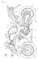
- Fig. 1 is a side view of an overall structure of a motorcycle according to a first embodiment.
- Fig. 2 to Fig. 19 are figures that illustrate in more detail the structure of funnels of the motorcycle according to the first embodiment shown in Fig. 1. Note that, the first embodiment explains about a motorcycle that is one example of a vehicle of the present teaching. In the figures, the arrow FWD indicates a forward direction of the motorcycle in the direction that it runs. First, the structure of the motorcycle according to the first embodiment will be explained with reference to Fig. 1 to Fig. 19.
- a front end section of a main frame 2 is connected to a head pipe 1.
- the main frame 2 as can be seen from Fig. 3, is disposed such that it splits and extends to the left and right with respect to the forward direction of a vehicle body.
- the main frame 2 is formed to extend downwards to the rear side.
- a seat rail 3 that extends upward to the rear side is connected to the main frame 2.
- a steering mechanism 4 is turnably attached to the head pipe 1.
- a handle 5 is attached to the upward side of the steering mechanism 4, and a clutch lever 6 is attached to the handle 5.
- a front fork 7 is attached to a downward side of the steering mechanism 4, and a front wheel 8 is rotatably mounted to a lower end section of the front fork 7.
- a front end section of a swing arm 10 is attached via a pivot bearing 9 to a rear end section of the main frame 2.
- a rear wheel 11 is rotatably mounted to a rear end section of the swing arm 10.
- a fuel tank 12 is disposed to the upward side of the main frame 2 so as to cover a rear side of a cleaner box 25, described hereinafter.
- a seat 13 is disposed to the upward side of the seat rail 3, and an engine 14 is mounted at the downward side of the main frame 2.
- the engine 14, as shown in Fig. 4, includes a piston 15, a cylinder 16, a cylinder head 17, and a throttle body 18.
- the piston 15 is fitted inside the cylinder 16 and the cylinder head 17 is disposed so as to block the opening at one end of the cylinder 16.
- an intake port 17a and an intake port 17b are formed in the cylinder head 17.
- the intake port 17a is provided to supply an air-fuel mixture including air and fuel to a combustion chamber 16a of the cylinder 16.
- the intake port 17b is provided to exhaust residual gas remaining after combustion from the combustion chamber 16a of the cylinder 16.
- an intake value 19a and an intake value 19b are respectively provided in the intake port 17a and the intake port 17b.
- the throttle body 18 is attached to an opening of the intake port 17a.
- an injector 20 is attached to the throttle body 18 in order to inject fuel to the intake port 17a.
- an exhaust pipe 21 is attached to an opening of the intake port 17b. This exhaust pipe 21 is connected to a muffler 22 (refer to Fig. 1 and Fig. 2).
- a muffler 22 (refer to Fig. 1 and Fig. 2).
- the engine 14 of the first embodiment of the invention is a 4-cylinder engine.
- a front cowl 23 that includes an upper cowl 23a and a lower cowl 23b is provided so as to cover a front side of the vehicle body.
- Intake holes 23c are provided in a front side of the lower cowl 23b.
- Fig. 1 and Fig. 2 only show, with respect to the forward direction of the vehicle body, the left side intake hole 23c.
- a pair of the intake holes 23c is provided in a left-right symmetrical manner with respect to the forward direction of the vehicle body.
- air ducts 24 are connected to the intake holes 23c of the lower cowl 23b.
- the cleaner box 25 which is supplied with air form the air ducts 24, is disposed between the main frame 2 that branches to the left and right.
- a cover 25a made of resin is positioned so as to cover an upper surface of a front section of the cleaner box 25.
- a rear section and a rear section upper surface of the cleaner box 25 are covered by the fuel tank 12.
- a protrusion 25b is provided at the rear section of the cleaner box 25 and protrudes to the outside of the cleaner box 25. The protrusion 25b, as can be seen in Fig.
- an air filter 26 for purifying the air supplied from the air ducts 24 is provided inside the cleaner box 25.
- the cleaner box 25 is just one example of a "case” of the present teaching
- the air filter 26 is just one example of an "air filter portion" of the present teaching.
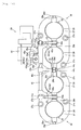
- fixed funnels 27, moveable funnels 28, and a funnel moving mechanism 29 are provided inside the cleaner box 25.
- One each of the fixed funnel 27 and the moveable funnel 28 are provided for each cylinder 16 of the engine 14.
- the fixed funnels 27 are fixed with respect to the cleaner box 25 and function to introduce purified air inside the cleaner box 25 to the intake ports 17a.
- the moveable funnels 28 are disposed on the intake side (the upstream side) of the fixed funnels 27, and function along with the fixed funnels 27 to introduce purified air inside the cleaner box 25 to the intake ports 17a.
- each moveable funnel 28 is structured so as to be moveable between a separation position and a contacting position.
- the separation position (the state shown in Fig. 7 and Fig. 8) is a position at which an opening 28a of the moveable funnel 28 on the fixed funnel 27 side is separated away from an opening 27a on the intake side of the fixed funnel 27.
- the contacting position (the state shown in Fig. 9 and Fig. 10) is a position at which the opening 28a of the moveable funnel 28 is placed in contact with the opening 27a of the fixed funnel 27. Note that, as shown in Fig. 4, when the moveable funnel 28 is moved to the separation position (the state shown in Fig. 7 and Fig.
- the intake pipe that connects from the cleaner box 25 to the cylinder 16 is structured by the fixed funnel 27, the throttle body 18, and the intake port 17a.
- the moveable funnel 28 is moved to the contacting position (the state shown in Fig. 9 and Fig. 10)
- the intake pipe that connects from the cleaner box 25 to the cylinder 16 is structured by the moveable funnel 28, the fixed funnel 27, the throttle body 18 and the intake port 17a.
- the funnel moving mechanism 29 functions to move the moveable funnels 28 between the separation position and the contacting position. Note that, the separation position and the contacting position are just examples of a "first position" and a "second position" of the present teaching.
- the fixed funnels 27 are structured such that neighboring pairs of the fixed funnels 27 are integrally formed via a connecting section 27b. More specifically, the first embodiment of the invention includes two of a component 30 in which neighboring pairs of fixed funnels 27 are integrated. Further, three screw insertion holes 27c are respectively formed in each component 30 that integrates the pair of fixed funnels 27. Screws 31 (refer to Fig. 14) are inserted in the screw insertion holes 27c. In addition, as shown in Fig. 14, each fixed funnel 27 (the component 30) is attached to both the cleaner box 25 and the throttle body 18 by screwing the screws 31 into the screw insertion holes 27c. Note that, screw insertion holes 25a into which the screws 31 are inserted are provided in the cleaner box 25.
- a strut 27d is integrally provided with the component 30 that integrates the pair of fixed funnels 27.
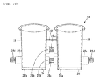
- the moveable funnels 28 have a structure in which neighboring pairs of moveable funnels 28 are formed integrally via a pair support shafts 28b.
- the first embodiment includes a pair of components 32 in which neighboring pairs of moveable funnels 28 are integrated.
- the support shafts 28b are positioned between the pair of moveable funnels 28 of each component 32. Note that, as a result of the support shaft 28b being supported by parallel links 42, described hereinafter, the moveable funnels 28 (the component 32) are held in a moveable manner. Further, thin diameter sections 28c are formed in the support shafts 28b.
- support shafts 28e having thin diameter sections 28d are provided at the outer side surface of the component 32 that integrates the neighboring pairs of moveable funnels 28.
- a strengthening rib 28f is provided between the pair of moveable funnels 28 of the component 32.
- two of the component 32 that integrates the pair of moveable funnels 28 are positioned such that the end surfaces of the respective thin diameter sections 28d of the support shafts 28e face each other.
- a split bush 33 is mounted on each thin diameter section 28c of the support shaft 28b of the moveable funnels 28 (the component 32).
- This split bush 33 functions to allow turning of the parallel link 42 with respect to the support shaft 28b, described hereinafter.
- the split bush 33 is also mounted on the thin diameter sections 28d of the support shafts 28e positioned between the components 32 that integrate the pairs of moveable funnels 28. Note that, only one of the split bush 33 is positioned between the components 32 that integrate the pairs of moveable funnels 28. This split bush 33 is mounted so as to straddle between the thin diameter sections 28d of the pair of support shafts 28e.
- a rubber lip 34 is mounted on the end section of each moveable funnel 28 on the fixed funnel 27 side. This rubber lip 34 functions to seal the gap between the moveable funnel 28 and the fixed funnel 27 when the moveable funnel 28 is moved to the contacting position (the state shown in Fig. 10).
- the funnel moving mechanism 29 uses the parallel link 42 to move the moveable funnel 28 between the separation position (the state shown in Fig. 7 and Fig. 8) and the contacting position (the state shown in Fig. 9 and Fig. 10).
- the funnel moving mechanism 29 has a concrete structure in which the end sections of the turning shafts 41 are turnably supported in the turning shaft support holes 27e of the strut 27d provided on the fixed funnel 27 (the component 30). Further, stepped sections 41 a are provided in one end section and another end section of each turning shaft 41, and these stepped sections 41 a abut with respective opening end sections of the turning shaft support holes 27e of the strut 27d. As a result, movement in the axial direction of the turning shafts 41 is controlled.
- the parallel links 42 are attached respectively to the one end section and the other end section sides of the turning shafts 41 so as to turn along with the turning shafts 41.
- the parallel links 42 are just one example of a "link mechanism" of the present teaching.
- the parallel links 42 include an upper side link lever 43 attached to the turning shaft 41 at the upper side, and a lower side link lever 44 attached to the turning shaft 41 at the lower side.
- the upper side link lever 43 and the lower side link lever 44 are just examples of a "link lever" of the present teaching.
- the upper side link lever 43 has a fitting section 43a, a turning shaft insertion hole 43b, and a pair of stoppers 43c and 43d.
- the support shaft 28b (the thin diameter section 28c) of the upper side of the moveable funnel 28 is fitted via the split bush 33 in the fitting section 43a of the upper side link lever 43.
- the upper side link lever 43 is turnable with respect to the upper side support shaft 28b.
- the upper side turning shaft 41 is fixed to the turning shaft insertion hole 43b of the upper side link lever 43 such that the upper side link lever 43 turns along with the upper side turning shaft 41.
- the stopper 43c of the upper side link lever 43 functions to control turning of the upper side link lever 43 in direction A by abutting with the strut 27d of the fixed funnel 27 when the upper side link lever 43 has turned a determined amount in direction A.
- the stopper 43d of the upper side link lever 43 functions to control turning in direction B of the upper side link lever 43 by abutting with the strut 27d of the fixed funnel 27 when the upper side link lever 43 has turned a determined amount in direction B.
- the arrow showing direction A is just one example of a "first direction" of the present teaching and the arrow showing direction B is just one example of a "second direction" of the present teaching.
- the support section 43e is structured by a pair of retaining tabs 43g in which respective notches 43f are formed, and is positioned at the opposite side to the fitting section 43a. Note that, the support section 43e, described above, is not provided in the lower side link lever 44 that provides the other support for the moveable funnels 28 (the component 32).
- the lower side link lever 44 has a fitting section 44a and a turning shaft insertion hole 44b.
- the lower side support shaft 28b (the thin diameter section 28c) of the moveable funnel 28 is fitted to the fitting section 44a of the lower side link lever 44 via the split bush 33.
- the lower side link lever 44 is turnable with respect to the lower side support shaft 28b.
- the lower side turning shaft 41 is fixed in the turning shaft insertion hole 44b of the lower side link lever 44 such that the lower side link lever 44 turns along with the lower side turning shaft 41.
- a link lever 44d having a fitting section 44a, and a turning shaft insertion hole 44b like the lower side link lever 44, and a split section 44c is positioned between the components 32 that integrate the pairs of moveable funnels 28.
- each moveable funnel 28 moves in the direction away from the fixed funnel 27.
- each moveable funnel 28 moves in the direction toward the fixed funnel 27.
- the turning amount of the parallel links 42 is adjusted such that the position of an opening surface 28g (refer to Fig. 7, Fig. 8 and Fig. 10) of the moveable funnel 28 on the side of the opening 27a of the fixed funnel 27 in the separation position (the state of Fig. 8), and the position of the opening surface 28g (refer to Fig. 7, Fig.
- the turning amount of the parallel links 42 is adjusted such that the position of the lower side support shaft 28b in the separation position (the state shown in Fig. 8) when viewed from the opening direction of the fixed funnel 27, and the position of the lower side support shaft 28b in the contacting position (the state shown in Fig. 10) when viewed from the opening direction of the fixed funnel 27 are the same.
- the turning amount of the parallel links 42 is adjusted such that the position of the upper side support shaft 28b in the separation position (the state shown in Fig. 8) when viewed from the opening direction of the fixed funnel 27, and the position of the lower side support shaft 28b in the contacting position (the state shown in Fig. 10) when viewed from the opening direction of the fixed funnel 27 are the same.
- the turning amount of the parallel links 42 is adjusted such that the position of the upper side support shaft 28b in the separation position (the state shown in Fig.
- the turning amount of the parallel links 42 is adjusted such that the that the position of the upper side support shaft 28b in the contacting position (the state shown in Fig. 10) when viewed from the opening direction of the fixed funnel 27, and the position of the lower side support shaft 28b in the contacting position (the state shown in Fig. 10) when viewed from the opening direction of the fixed funnel 27 are the same.
- the stopper 43c of the parallel link 42 (the upper side link lever 43) is adjusted so as to abut with the strut 27d when the moveable funnel 28 reaches the separation position. Further, as shown in Fig. 10, the stopper 43d of the parallel link 42 (the upper side link lever 43) is adjusted so as to abut with the strut 27d when the moveable funnel 28 reaches the contacting position.
- each parallel link 42 including the upper side link lever 43 and the lower side link lever 44 is caused to turn by driving force of a motor 45.
- an output shaft 45a of the motor 45 is attached to one end section of a turning lever 46.
- the motor 45 is just one example of a "drive source” of the present teaching
- the output shaft 45a is just one example of a “drive shaft” and a “motor drive shaft” of the present teaching.
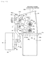
- the motor 45 is located at a position that is between an upstream side section 25c that is an upstream section of the flow of air from the air filter 26 disposed inside the cleaner box 25, and a downstream side section 25d that is a downstream section of the flow of air from the air filter 26. Further, the motor 45 is provided at the outer side of the cleaner box 25. More specifically, the cleaner box 25 is provided with a U-shape, and provided with the upstream side section 25c to the upstream of the air filter 26 and the downstream side section 25d to the downstream of the air filter 26 that face each other. Further, the motor 45 is positioned between the upstream side section 25c to the upstream of the air filter 26 and the downstream side section 25d to the downstream of the air filter 26 that face each other.
- a generally spherical support member 46a is provided on the other end section of the turning lever 46.
- a connecting member 47 is attached to the spherical support member 46a of the turning lever 46 such that the connecting member 47 is capable of rocking with respect to the support member 46a.
- a moving shaft 48 is attached to the connecting member 47.
- an upper side pressing member 48a and a lower side pressing member 48b are provided on the moving shaft 48.
- the moving shaft 48 is just one example of a "connecting lever" of the present teaching.
- the upper side pressing member 48a is positioned at the end section of the moving shaft 48 at the opposite side from the connecting member 47 (refer to Fig. 16).
- the lower side pressing member 48b is positioned in a region that is a predetermined distance of separation in the downward direction from the upper side pressing member 48a of the moving shaft 48.
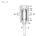
- a moving member 49 is positioned at the side of the one end section of the moving shaft 48 where the upper side pressing member 48a (the lower side pressing member 48b) is provided. Both side surfaces of this moving member 49, as can be seen in Fig. 16, are provided with protrusions 49a that engage with the pair of notches 43f formed in the upper side link lever 43. Further, the retaining tabs 43g of the upper side link lever 43 are positioned so as to sandwich the moving member 49, and the notches 43f are engaged with the protrusions 49a. As a result, the upper side link lever 43 (the support section 43e) is supported by the moving member 49. Moreover, as shown in Fig.
- bushes 50a and 50b for slidably supporting the moving shaft 48 are provided inside the moving member 49.
- the bushes 50a and 50b are disposed between the upper side pressing member 48a and the lower side pressing member 48b. Further, a compression spring 51 is attached between the bush 50a and the bush 50b inside the moving member 49.
- the compression spring 51 when the turning lever 46 is turned in direction C by the driving force of the motor 45 (the state shown in Fig. 16), as shown in Fig. 17, the compression spring 51 generates energizing force in direction D as a result of movement of the moving shaft 48 in direction D. As a result, the moving member 49 is energized in direction D by the compression spring 51. Accordingly, as can be seen in Fig. 8, the energizing force of the compression spring 51 (refer to Fig. 17), is transmitted to the parallel link 42 via the moving member 49, whereby the parallel link 42 is turned in direction A.
- the compression spring 51 when the turning lever 46 is turned in direction E by the driving force of the motor 45 (the state shown in Fig. 18), the compression spring 51 generates energizing force in direction F as a result of movement of the moving shaft 48 in direction F, as shown in Fig. 19. As a result, the moving member 49 is energized in direction F by the compression spring 51. Accordingly, as can be seen in Fig. 10, the energizing force of the compression spring 51 (refer to Fig. 19), is transmitted to the parallel link 42 via the moving member 49, whereby the parallel link 42 is turned in direction B.
- the turning lever 46 is turned in direction C by the motor 45 of the funnel moving mechanism 29. Accordingly, the moving shaft 48 is moved in direction D.
- the compression spring 51 (refer to Fig. 17) generates energizing force in direction D, whereby the moving member 49 is moved in direction D.
- the parallel link 42 is turned in direction A. Following this, the parallel link 42 continues turning in direction A until the stopper 43c of the upper side link lever 43 abuts with the strut 27d.
- the moveable funnel 28 is moved to the separation position at which the opening surface of the opening 28a of the moveable funnel 28 is held parallel with respect to the opening surface of the opening 27a of the fixed funnel 27. Accordingly, when the engine 14 (refer to Fig. 4) is rotating at high speed, the fixed funnel 27, the throttle body 18 (refer to Fig. 4), and the intake port 17a (refer to Fig. 4) structure the intake pipe. As a result the intake pipe is shortened. Note that, when the engine 14 shown in Fig. 4 is rotating at high speed and the intake pipe is shortened, high pressure-pressure waves can more easily reach the opening at the cylinder 16 side of the intake port 17a when the intake valve 19a is open, whereby intake efficiency is improved.
- the intake pipe is lengthened.
- the moveable funnel 28 is moved to the contacting position.
- the turning lever 46 is turned in direction E by the motor 45 of the funnel moving mechanism 29. Accordingly, the moving shaft 48 is moved in direction F.
- the compression spring 51 (refer to Fig. 19) generates energizing force in direction F, whereby the moving member 49 is moved in direction F.
- the parallel link 42 is turned in direction B. Following this, the parallel link 42 continues turning in direction B until the stopper 43d of the upper side link lever 43 abuts with the strut 27d.
- the moveable funnel 28 is moved to the contacting position at which the opening surface of the opening 28a of the moveable funnel 28 is held parallel with respect to the opening surface of the opening 27a of the fixed funnel 27. Accordingly, when the engine 14 (refer to Fig. 4) is rotating at low speed, the moveable funnel 28, the fixed funnel 27, the throttle body 18 (refer to Fig. 4), and the intake port 17a (refer to Fig. 4) structure the intake pipe. As a result the intake pipe is lengthened. Note that, when the engine 14 shown in Fig. 4 is rotating at low speed and the intake pipe is lengthened, high pressure-pressure waves can more easily reach the opening at the cylinder 16 side of the intake port 17a when the intake valve 19a is open, whereby intake efficiency is improved.
- the motor 45 that provides drive via the drive shaft 45a in order to move the moveable funnel 28 is disposed, with respect to the moveable funnel 28, at the opposite side to the fuel tank 12 that is disposed to the rear direction side in the running direction of the motorcycle (the direction of the FWD arrow) from the moveable funnel 28.
- space for disposing the motor 45 etc. that moves the moveable funnel 28 does not need to be provided at the fuel tank 12 side, and this space can be used for disposing the fuel tank 12.
- the volume of the fuel tank 12, which is disposed to the rear of the moveable funnel 28 used to vary air intake is inhibited from being reduced.
- the parallel link 42, the upper side link lever 43, the lower side link lever 44 and the like are provided inside the cleaner box 25, and the motor 45 is provided outside the cleaner box 25.
- the motor 45 is provided outside the cleaner box 25.
- the motor 45 is positioned between the upstream side section 25c that is the upstream section of the flow of air from the air filter 26 disposed inside the cleaner box 25, and the downstream side section 25d that is the downstream section from the air filter 26. Further, the motor 45 is provided at the outer side of the cleaner box 25. As a result, it is easily possible to ensure space for disposing the motor 45.
- the first embodiment is structured such that one end side of the turning lever 46 is connected to the output shaft 45a in order to cover rotational motion of the output shaft 45a to linear motion. Accordingly, the turning lever 46 is able to cover the rotational motion of the output shaft 45a to the linear motion required by the moveable funnels 28.
- the first embodiment is also provided with the moving shaft 48 that connects the other end side of the turning lever 46 and the upper side link lever 43 via the moving member 49.
- the linear motion converted by the turning lever 46 can easily be transmitted to the upper side link lever 43 via the moving shaft 48.
- each parallel link 42 is used to move the moveable funnel 28. Accordingly, the opening 27a of the moveable funnel 28 on the fixed funnel 27 side can be separated away from and brought into contact with respect to the opening 27a of the intake side of the fixed funnel 27, while the opening 28a of the moveable funnel 28 on the fixed funnel 27 side is held parallel with respect to the opening surface 27a of the fixed funnel 27 on the intake side. As a result, even if the opening 28a of the moveable funnel 28 on the fixed funnel 27 side is separated away from the opening 27a of the fixed funnel 27 on the intake side, air that enters through the fixed funnel 27 having passed through the moveable funnel 28 is able to flow linearly. Accordingly, it is possible to inhibit flow resistance of the air from increasing. As a result, when the moveable funnel 28 is separated away from the fixed funnel 27, reduction of intake efficiency can be inhibited from occurring.
- the turning amount of each parallel link 42 is adjusted such the position of the opening surface 28g of the moveable funnel 28 on the side of the opening 27a of the fixed funnel 27 in the separation position, and the position of the opening surface 28g of the moveable funnel 28 on the side of the opening 27a of the fixed funnel 27 in the contacting position are the same when viewed from the opening direction of the fixed funnel 27.
- the moveable funnel 28 is moved from the contacting position to the separation position (in the case that the engine 14 is rotating at high speed)
- all of the air that enters through the fixed funnel 27 having passed through the moveable funnel 28 is able to flow in a substantially linear manner. Accordingly, it is possible to inhibit flow resistance of the air from increasing.
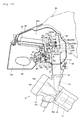
- Fig. 20 to Fig. 23 are figures that illustrate in detail the structure of the periphery area of the funnels of the motorcycle according to a second embodiment.
- Fig. 20 to Fig. 23 will be used to explain the example of the second embodiment in which, unlike the above-described first embodiment, a motor 65 that is disposed to the outer side of a cleaner box 55 is attached to the cleaner box 55 in a sealed manner.
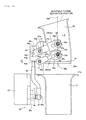
- the motor 65 is located at a position that is between an upstream side section 55c that is an upstream section of the flow of air from an air filter 56 disposed inside the cleaner box 55 made of resin, and a downstream side section 55d that is a downstream section of the flow of air from the air filter 56. Further, the motor 65 is provided at the outer side of the cleaner box 55. More specifically, the cleaner box 55 is provided with a U-shape, and provided with the upstream side section 55c to the upstream of the air filter 56 and the downstream side section 55d to the downstream of the air filter 56 that face each other.
- the motor 65 is positioned between the upstream side section 25c to the upstream of the air filter 56 and the downstream side section 25d to the downstream of the air filter 56 that face each other.
- the motor 65 is just one example of a "drive source" of the present teaching.
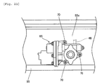
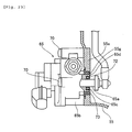
- the motor 65 as can be seen in Fig. 20 and Fig. 21, is attached by insertion of three screws 70 into screw holes 55f provided in a wall 55e of the cleaner box 55.
- the screw holes 55f as shown in Fig. 22, are respectively formed in areas that correspond with the attachment positions of the screws 70 by embedding metal-made screw hole components 71 in the wall 55e of the resin-made cleaner box 55.
- the cleaner box 55 is just one example of a "case” of the present teaching
- the air filter 56 is just one example of an "air filter portion" of the present teaching.
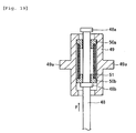
- the motor 65 includes an output shaft 65a and a motor body 65b.
- a bearing accommodating section 65c that has a recess-like shape is provided integrally with the motor body 65b around the output shaft 65a in the motor body 65b.
- a seal bearing 72 that functions as a seal is pressed fitted in the bearing accommodating section 65c, and the output shaft 65a is inserted inside the seal bearing 72.
- the seal bearing 72 is just one example of a "bearing having a seal function" of the present teaching.
- a ring-shaped protrusion 65d is provided integrally with the motor body 65b in an attachment section of the motor 65 for attachment to the cleaner box 55.
- a grommet 73 made of rubber is mounted around the outer periphery surface of the protrusion 65d.
- the grommet 73 is just one example of an "elastic member" of the present teaching.
- the protrusion 65d to which the grommet 73 is mounted is fitted in a hole 55g provided in the wall 55e of the cleaner box 55. More specifically, the protrusion 65d of the motor 65 is fitted in the hole 55g of the cleaner box 55 such that the grommet 73 seals therebetween. Accordingly, it is possible to inhibit exit and entry of air from/to the inside of the cleaner box 55 from the gap between the motor 65 and the cleaner box 55.
- the seal bearing 72 is fitted to a bearing groove 65b of the motor 65 including the output shaft 65a that extends from the outside to the inside of the cleaner box 55.
- the rubber-made grommet 73 is fitted around the protrusion 65c provided integrally with the body of the motor 65, and the protrusion 65c fitted with the grommet 73 is fitted into the hole 55g of the cleaner box 55.
- the present teaching is applied to a motorcycle.
- the present teaching is not limited to this structure, and may be applied to vehicles other than a motorcycle.
- the present teaching is applied to a vehicle equipped with a 4-cylinder engine.
- the present teaching is not limited to this structure, and may be applied to a vehicle equipped with a multi-cylinder engine that is different to a 4-cyliner engine, or applied to a vehicle equipped with a single cylinder engine.
- pairs of the moveable funnels are integrated.
- the present teaching is not limited to this structure and three or more of the moveable funnels may be integrated. Further, a separate moveable funnel may be provided for each cylinder.
- the above embodiments have a structure in which the moveable funnels are moved by the parallel links (the link mechanism) having the plurality of the link levers.
- the present teaching is not limited to this structure and a link mechanism having a single arm (lever) may be used to move the moveable funnels.
- a first embodiment which includes: an engine having an intake port; a fixed funnel that introduces air to the intake port of the engine; a moveable funnel that is moveably disposed on the intake side of the fixed funnel and that introduces air to the intake port of the engine along with the fixed funnel; a link mechanism that moveably supports the moveable funnel; a fuel tank disposed to the rear side of the moveable funnel when the vehicle is viewed from a side thereof; and a drive source that drives the link mechanism in order to move the moveable funnel, the drive source being disposed, if the moveable funnel is taken as a reference point, to the opposite side from the side where the fuel tank is disposed.
- the drive source which drives the link mechanism in order to move the moveable funnel, is disposed, with respect to the moveable funnel, to the opposite side from the side where the fuel tank is disposed, the fuel tank being disposed to the rear side of the moveable funnel when the vehicle is viewed from the side thereof.
- space for disposing the drive source that moves the moveable funnel does not need to be provided at the fuel tank side, and this space can be used for disposing the fuel tank.
- the volume of the fuel tank, which is disposed to the rear of the moveable funnel used to vary air intake is inhibited from being reduced.
- the vehicle according to the first embodiment described above preferably includes a case in which the fixed funnel and the moveable funnel are disposed. Further, preferably, the link mechanism is disposed inside the case, and the drive source is disposed to the outside of the case. As a result of adopting this structure, it is no longer necessary to arrange electrical wiring or the like for driving the drive source inside the case, which vaporized gasoline coming from the direction of the engine enters. Accordingly, it is possible to inhibit deterioration of the electrical wiring caused by vaporized gasoline that has entered into the case.
- an air filter portion is provided inside the case, and that the drive source is positioned between an upstream side section and a downstream side section of the case, the upstream side section and the downstream side section being respectively upstream and downstream from the air filter portion. If this structure is adopted, it is easily possible to ensure space for disposing the drive source.
- the drive source includes a drive shaft that extends from the outside to the inside of the case, and that the vehicle further includes a seal member that seals a gap between the drive shaft and the case. If this structure is adopted, air inside the case is inhibited from leaking to the outside of the case through the gap between the drive shaft and the case. As a result, it is possible to inhibit the occurrence of interference of the flow of air that enters the engine in the inside of the case.
- the seal member includes a bearing having a seal function, and that the bearing rotatably supports the drive shaft of the drive source. If this structure is adopted, the bearing having the seal function is able to simply seal the surrounding of the drive shaft.
- the seal member includes an elastic member disposed in the gap between the drive shaft of the drive source and the case. If this structure is adopted, it is easily possible to seal the gap between the drive shaft and the case.
- the drive source includes a motor
- the motor includes a motor drive shaft that extends from the outside to the inside of the case
- the vehicle further includes a turning lever that has one end side connected to the motor drive shaft, and that converts rotational motion of the motor drive shaft to linear motion. If this structure is adopted, the turning lever can be used to convert the rotational motion of the motor drive shaft to linear motion necessary for the moveable funnel.
- the above structure preferably includes a connecting lever that connects the other end side of the turning lever to the link mechanism. If this structure is adopted, the linear motion converted by the turning lever can be easily transmitted to the link mechanism via the connecting lever.
- the link mechanism includes a parallel link that has a plurality of link levers that moveably support the moveable funnel such that it is capable of parallel movement. If this structure is adopted, the parallel link is used to move the moveable funnel. As a result, the opening of the moveable funnel on the fixed funnel side can be separated away from and brought into contact with respect to the opening of the fixed funnel on the intake side, while the opening surface of the moveable funnel on the fixed funnel side is held parallel with respect to the opening surface of the fixed funnel on the intake side.
- the link mechanism includes a parallel link that has a plurality of link levers that moveably support the moveable funnel such that it is capable of parallel movement; and that, among the link levers, at least one of the link levers has one end that is connected to the connecting lever and has another end that is connected to the moveable funnel. If this structure is adopted, the driving force of the drive source can be easily transmitted to the moveable funnel while the opening surface of the moveable funnel on the fixed funnel side is held parallel with the opening surface of the fixed funnel on the intake side.
- the link levers turn in one direction to move an opening of the moveable funnel on the fixed funnel side to a first position at which the opening is away from an opening on the intake side of the fixed funnel; and in the case that the engine is rotating at low speed, the link levers turn in a second direction that is opposite to the first direction to move the opening of the moveable funnel on the fixed funnel side to a second position at which the opening is in contact with the opening on the intake side of the fixed funnel.
- the moveable funnel when the rotation speed of the engine changes from low to high, the moveable funnel can be moved from the second position to the first position while the opening surface of the moveable funnel on the fixed funnel side is held parallel with the opening surface on the intake side of the fixed funnel.
- air that enters through the fixed funnel having passed through the moveable funnel is able to flow linearly. Accordingly, it is possible to inhibit flow resistance of the air from increasing. As a result, when the engine is rotating at high speed, reduction of intake efficiency can be inhibited from occurring.
- a turning amount of the link lever is adjusted such that the position of the opening surface of the moveable funnel on the intake side of the fixed funnel in the first position is the same as the position of the opening surface of moveable funnel on the intake side of the fixed funnel in the second position when viewed from an opening direction of the fixed funnel. If this structure is adopted, when the moveable funnel is moved from the second position to the first position (when the engine is rotating at high speed), all of the air that enters through the fixed funnel having passed through the moveable funnel is able to flow in a substantially linear manner. Accordingly, it is possible to inhibit flow resistance of the air from increasing.
- a motorcycle which includes an engine 14 having an intake port 17a; a fixed funnel 27 that introduces air to the intake port 17a of the engine 14; a moveable funnel 28 that is moveably disposed on the intake side of the fixed funnel 27 and that introduces air to the intake port 17a of the engine 14 along with the fixed funnel 27; a parallel link 42 that moveable supports the moveable funnel 28; a fuel tank 12 disposed to the rear side of the moveable funnel 28 in a running direction of the motorcycle; and a motor 45 that is disposed, with respect to the moveable funnel 28, on the opposite side to the fuel tank 12, and that drives the parallel link 42 to move the moveable funnel 28.
- a vehicle comprising: an engine having an intake port; a fixed funnel that introduces air to the intake port of the engine; a moveable funnel that is moveably disposed on the intake side of the fixed funnel and that introduces air to the intake port of the engine along with the fixed funnel; a link mechanism that moveably supports the moveable funnel; a fuel tank disposed to the rear side of the moveable funnel when the vehicle is viewed from a side thereof; and a drive source that drives the link mechanism in order to move the moveable funnel, the drive source being disposed, if the moveable funnel is taken as a reference point, to the opposite side from the side where the fuel tank is disposed.
- the vehicle may further comprise: a case in which the fixed funnel and the moveable funnel are disposed, wherein the link mechanism is disposed inside the case, and the drive source is disposed to the outside of the case.
- an air filter portion is provided inside the case, and the drive source is positioned between an upstream side section and a downstream side section of the case, the upstream side section and the downstream side section being respectively upstream and downstream from the air filter portion.
- the drive source includes a drive shaft that extends from the outside to the inside of the case, and the vehicle further comprises a seal member that seals a gap between the drive shaft and the case.
- the seal member includes a bearing having a seal function, the bearing rotatably supporting the drive shaft of the drive source.
- the seal member includes an elastic member disposed in the gap between the drive shaft of the drive source and the case.
- the drive source includes a motor
- the motor includes a motor drive shaft that extends from the outside to the inside of the case
- the vehicle further comprises a turning lever that has one end side connected to the motor drive shaft, and that converts rotational motion of the motor drive shaft to linear motion.
- the vehicle may further comprise: a connecting lever that connects the other end side of the turning lever to the link mechanism.
- the link mechanism comprises a parallel link that has a plurality of link levers that moveably support the moveable funnel such that it is capable of parallel movement.
- the link mechanism comprises a parallel link that has a plurality of link levers that moveably support the moveable funnel such that it is capable of parallel movement; and among the link levers, at least one of the link levers has one end that is connected to the connecting lever and has another end that is connected to the moveable funnel.
- the link levers in the case that the engine is rotating at high speed, turn in one direction to move an opening of the moveable funnel on the fixed funnel side to a first position at which the opening is away from an opening on the intake side of the fixed funnel, and in the case that the engine is rotating at low speed, the link levers turn in a second direction that is opposite to the first direction to move the opening of the moveable funnel on the fixed funnel side to a second position at which the opening is in contact with the opening on the intake side of the fixed funnel.
- a turning amount of the link levers is adjusted such that the position of an opening surface of the moveable funnel on the intake side of the fixed funnel in the first position is the same as the position of the opening surface of moveable funnel on the intake side of the fixed funnel in the second position when viewed from an opening direction of the fixed funnel.
Landscapes
- Engineering & Computer Science (AREA)
- Chemical & Material Sciences (AREA)
- Combustion & Propulsion (AREA)
- Mechanical Engineering (AREA)
- General Engineering & Computer Science (AREA)
- Health & Medical Sciences (AREA)
- Biomedical Technology (AREA)
- Physics & Mathematics (AREA)
- Geometry (AREA)
- Characterised By The Charging Evacuation (AREA)
- Cooling, Air Intake And Gas Exhaust, And Fuel Tank Arrangements In Propulsion Units (AREA)
Abstract
Description
- The present invention relates to a vehicle and more particularly to a vehicle equipped with a funnel for introducing air to an intake port of an engine.
- Intake devices are known that are equipped with a funnel for introducing air to an intake port of an engine (for example, see Patent Document 1).
Patent Document 1 discloses an intake device equipped with a high speed funnel (a fixed funnel) for introducing air that enters from a front side (an upstream side of a case) to an intake port of an engine; a low speed funnel provided in the upper section of the high speed funnel; a moveable slide valve positioned between the high speed funnel and the low speed funnel and that can be slid to the low speed funnel side; a turning arm (connecting lever) that is attached to the slide valve; and a motor that drives the turning arm via an intermediate gear, a rocking gear, and the like. The intake device is structured such that, when the engine is rotating at low speed, the slide valve connects between the high speed funnel and the low speed funnel such that air intake is performed in a manner suitable for low speed rotation. In addition, when the engine is rotating at high speed, the slide valve moves inside the low speed funnel such that there is no longer connection between the high speed funnel and the low speed funnel. As a result, air intake is performed in a manner that is suitable for high speed rotation. In other words, the intake device performs variable air intake. Further, the motor and a section of the intermediate gear are positioned in a rear section to the outer side of a case (to the downstream side of the case) that covers the inside of the intake device. - Patent Document 1:
JP-UM-A-63-177627 - However, in the structure disclosed in
Patent Document 1, the motor for moving the slide valve to vary air intake, and a section of the intermediate gear are disposed in a rear section (the downstream side of the case) of the intake device. This causes the difficulty that the rear section (the downstream side of the case) is made larger. As a result, normally, the space for disposing the fuel tank, which is disposed to the rear of the intake device, is made smaller, which causes the problem that the volume of the fuel tank has to be made smaller. - The invention has been devised in light of the above-described problems and it is an object of the invention to provide a vehicle that can inhibit reduction of the volume of a fuel tank disposed to the rear of a moveable funnel that varies air intake.
- This objective is solved by a vehicle comprising: an engine having an intake port; a fixed funnel that introduces air to the intake port of the engine; a moveable funnel that is moveably supported by a funnel moving mechanism on the intake side of the fixed funnel and that introduces air to the intake port of the engine along with the fixed funnel; a fuel tank disposed to the rear side of the moveable funnel when the vehicle is viewed from a side thereof; and a drive source that drives the funnel moving mechanism in order to move the moveable funnel, the drive source being disposed, if the moveable funnel is taken as a reference point, to the opposite side from the side where the fuel tank is disposed.
- According to a preferred embodiment, the vehicle further comprises a case, in which the fixed funnel and the moveable funnel are disposed, wherein the funnel moving mechanism is disposed inside the case, and wherein the drive source is disposed to the outside of the case.
- Preferably, the funnel moving mechanism comprises a link mechanism that moveably supports the moveable funnel.
- Further, preferably an air filter portion is provided inside the case, and the drive source is positioned between an upstream side section and a downstream side section of the case, the upstream side section and the downstream side section being respectively upstream and downstream from the air filter portion.
- Still further, preferably the drive source includes a drive shaft that extends from the outside to the inside of the case, and the vehicle further comprises a seal member that seals a gap between the drive shaft and the case.
- Yet further still, preferably the seal member includes a bearing having a seal function, the bearing rotatably supporting the drive shaft of the drive source. Therein, the seal member may include an elastic member disposed in the gap between the drive shaft of the drive source and the case.
- Further, preferably the drive source includes a motor, the motor includes a motor drive shaft that extends from the outside to the inside of the case, and the vehicle further comprises a turning lever that has one end side connected to the motor drive shaft, and that converts rotational motion of the motor drive shaft to linear motion.
- According to another preferred embodiment, the vehicle further comprises a connecting lever that connects the other end side of the turning lever to the link mechanism.
- Preferably, the link mechanism comprises a parallel link that has a plurality of link levers that moveably support the moveable funnel such that it is capable of parallel movement.
- Further, preferably the link mechanism comprises a parallel link that has a plurality of link levers that moveably support the moveable funnel such that it is capable of parallel movement; and among the link levers, at least one of the link levers has one end that is connected to the connecting lever and has another end that is connected to the moveable funnel.
- Yet further, preferably in the case that the engine is rotating at high speed, the link levers turn in one direction to move an opening of the moveable funnel on the fixed funnel side to a first position at which the opening is away from an opening on the intake side of the fixed funnel, and in the case that the engine is rotating at low speed, the link levers turn in a second direction that is opposite to the first direction to move the opening of the moveable funnel on the fixed funnel side to a second position at which the opening is in contact with the opening on the intake side of the fixed funnel.
- Still further yet, preferably a turning amount of the link levers is adjusted such that the position of an opening surface of the moveable funnel on the intake side of the fixed funnel in the first position is the same as the position of the opening surface of moveable funnel on the intake side of the fixed funnel in the second position when viewed from an opening direction of the fixed funnel.
- In the following, the present invention is explained in greater detail with respect to several embodiments thereof in conjunction with the accompanying drawings, wherein:
- Fig. 1
- is a side view showing the overall structure of a motorcycle according to a first embodiment,
- Fig. 2
- is a partial cross sectional view of a periphery section of a fuel tank and a cleaner box of the motorcycle of the first embodiment shown in Fig. 1,
- Fig. 3
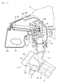
- is a side view of a periphery area of funnels of the motorcycle of the first embodiment shown in Fig. 1,
- Fig. 4
- is a side view of the periphery area of the funnels of the motorcycle of the first embodiment shown in Fig. 1,
- Fig. 5
- is a top view from the outside of the funnels and the fuel tank of the motorcycle of the first embodiment shown in Fig. 1,
- Fig. 6
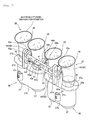
- is a front view of a periphery area of the funnels of the motorcycle of the first embodiment shown in Fig. 1,
- Fig.7
- is a perspective view showing a state when moveable funnels of the motorcycle of the first embodiment shown in Fig. 1 have been moved to a separation position,
- Fig. 8
- is a side view showing a state when the moveable funnels of the motorcycle of the first embodiment shown in Fig. 1 have been moved to the separation position,
- Fig. 9
- is a perspective view showing a state when the moveable funnels of the motorcycle of the first embodiment shown in Fig. 1 have been moved to a contacting position,
- Fig. 10
- is a side view showing a state when the moveable funnels of the motorcycle of the first embodiment shown in Fig. 1 have been moved to the contacting position,
- Fig. 11
- is a plan view that illustrates the detailed structure of the periphery area of the funnels of the motorcycle of the first embodiment shown in Fig. 1,
- Fig. 12
- is a perspective view of fixed funnels of the motorcycle of the first embodiment shown in Fig. 1,
- Fig. 13
- is a front view of the fixed funnels of the motorcycle of the first embodiment shown in Fig. 1,
- Fig. 14
- is a cross sectional view that illustrates the structure of screw insertion holes of the fixed funnels shown in Fig. 12 and Fig. 13,
- Fig. 15
- is a front view of the moveable funnels of the motorcycle of the first embodiment shown in Fig. 1,
- Fig. 16
- is a front view of a funnel moving mechanism of the motorcycle of the first embodiment shown in Fig. 1,
- Fig. 17
- is a cross sectional view that illustrates the structure of a moving member of the funnel moving mechanism shown in Fig. 16,
- Fig. 18
- is a front view of the funnel moving mechanism of the motorcycle of the first embodiment shown in Fig. 1,
- Fig. 19
- is a cross sectional view that illustrates the structure of the moving member of the funnel moving mechanism shown in Fig. 18,
- Fig. 20
- is a side view of a periphery area of funnels of a motorcycle according to a second embodiment,
- Fig. 21
- is a view along the direction of arrow P that illustrates the detailed attachment structure of a motor according to the second embodiment shown in Fig. 20,
- Fig. 22
- s a cross sectional view that illustrates the detailed attachment structure of the motor according to the second embodiment, and
- Fig. 23
- s a cross sectional view that illustrates the detailed attachment structure of the motor according to the second embodiment.
-
- 12
- Fuel tank
- 14
- Engine
- 17a
- Intake port
- 25, 55
- Cleaner box (Case)
- 25c, 55c
- Upstream side section
- 25d, 55d
- Downstream side section
- 26
- Air filter (Air filter portion)
- 27
- Fixed funnel
- 27a
- Opening
- 28
- Moveable funnel
- 28a
- Opening
- 28g
- Opening surface
- 42
- Parallel link (Link mechanism)
- 43
- Upper side link lever (Link lever, Link mechanism)
- 44
- Lower side link lever (Link lever, Link mechanism)
- 45, 65
- Motor (Drive source)
- 45a, 65a
- Output shaft (Drive shaft, Motor drive shaft)
- 46
- Turning lever
- 48
- Moving shaft (Connecting lever)
- 72
- Seal bearing (Bearing)
- 73
- Grommet (Elastic member)
- Fig. 7
Moveable funnel separation position - Fig. 8
Moveable funnel separation position - Fig. 9
Moveable funnel contacting position - Fig. 10
Moveable funnel contacting position - Hereinafter embodiments will be explained with reference to the drawings.
- Fig. 1 is a side view of an overall structure of a motorcycle according to a first embodiment. Fig. 2 to Fig. 19 are figures that illustrate in more detail the structure of funnels of the motorcycle according to the first embodiment shown in Fig. 1. Note that, the first embodiment explains about a motorcycle that is one example of a vehicle of the present teaching. In the figures, the arrow FWD indicates a forward direction of the motorcycle in the direction that it runs. First, the structure of the motorcycle according to the first embodiment will be explained with reference to Fig. 1 to Fig. 19.
- In the structure of the motorcycle according to the first embodiment, as shown by Fig. 1 and Fig. 2, a front end section of a
main frame 2 is connected to ahead pipe 1. Themain frame 2, as can be seen from Fig. 3, is disposed such that it splits and extends to the left and right with respect to the forward direction of a vehicle body. In addition, as can be seen from Fig. 1 and Fig. 2, themain frame 2 is formed to extend downwards to the rear side. Further, a seat rail 3 that extends upward to the rear side is connected to themain frame 2. In addition, asteering mechanism 4 is turnably attached to thehead pipe 1. Ahandle 5 is attached to the upward side of thesteering mechanism 4, and a clutch lever 6 is attached to thehandle 5. Further, afront fork 7 is attached to a downward side of thesteering mechanism 4, and afront wheel 8 is rotatably mounted to a lower end section of thefront fork 7. - In addition, a front end section of a
swing arm 10 is attached via apivot bearing 9 to a rear end section of themain frame 2. Arear wheel 11 is rotatably mounted to a rear end section of theswing arm 10. Further, afuel tank 12 is disposed to the upward side of themain frame 2 so as to cover a rear side of acleaner box 25, described hereinafter. In addition, aseat 13 is disposed to the upward side of the seat rail 3, and anengine 14 is mounted at the downward side of themain frame 2. - The
engine 14, as shown in Fig. 4, includes apiston 15, acylinder 16, acylinder head 17, and athrottle body 18. Thepiston 15 is fitted inside thecylinder 16 and thecylinder head 17 is disposed so as to block the opening at one end of thecylinder 16. Further, anintake port 17a and anintake port 17b are formed in thecylinder head 17. Theintake port 17a is provided to supply an air-fuel mixture including air and fuel to acombustion chamber 16a of thecylinder 16. Further, theintake port 17b is provided to exhaust residual gas remaining after combustion from thecombustion chamber 16a of thecylinder 16. Moreover, anintake value 19a and anintake value 19b are respectively provided in theintake port 17a and theintake port 17b. Thethrottle body 18 is attached to an opening of theintake port 17a. Further, aninjector 20 is attached to thethrottle body 18 in order to inject fuel to theintake port 17a. In addition, anexhaust pipe 21 is attached to an opening of theintake port 17b. Thisexhaust pipe 21 is connected to a muffler 22 (refer to Fig. 1 and Fig. 2). Note that, although only onecylinder 16 is shown in Fig. 4, in reality fourcylinders 16 are disposed at predetermined distances apart in the width direction of the vehicle. In other words, theengine 14 of the first embodiment of the invention is a 4-cylinder engine. - Further, as can be seen in Fig. 1 and Fig. 2, a
front cowl 23 that includes anupper cowl 23a and alower cowl 23b is provided so as to cover a front side of the vehicle body. Intake holes 23c are provided in a front side of thelower cowl 23b. Note that, Fig. 1 and Fig. 2 only show, with respect to the forward direction of the vehicle body, the leftside intake hole 23c. However, in reality a pair of theintake holes 23c is provided in a left-right symmetrical manner with respect to the forward direction of the vehicle body. Further,air ducts 24 are connected to the intake holes 23c of thelower cowl 23b. In addition, as shown in Fig. 1 to Fig. 3, thecleaner box 25, which is supplied with air form theair ducts 24, is disposed between themain frame 2 that branches to the left and right. - More specifically, as shown in Fig. 4, a
cover 25a made of resin is positioned so as to cover an upper surface of a front section of thecleaner box 25. In addition, a rear section and a rear section upper surface of thecleaner box 25 are covered by thefuel tank 12. In addition, as shown in Fig. 4 and Fig. 5, aprotrusion 25b is provided at the rear section of thecleaner box 25 and protrudes to the outside of thecleaner box 25. Theprotrusion 25b, as can be seen in Fig. 4, is provided so as to protrude to the outside at a region that corresponds to a rear section of an upper edge section of amoveable funnel 28, described hereinafter, such that the rear section of the upper edge section of themoveable funnel 28 does not come into contact with an inner surface of thecleaner box 25. As a result, as compared to when the entire rear section of thecleaner box 25 is made larger, it is possible to inhibit the volume of thefuel tank 12 from having to be made smaller. Further, as can be seen in Fig. 3 and Fig. 4, anair filter 26 for purifying the air supplied from theair ducts 24 is provided inside thecleaner box 25. Note that, thecleaner box 25 is just one example of a "case" of the present teaching, and theair filter 26 is just one example of an "air filter portion" of the present teaching. - Moreover, as shown in Fig. 3, Fig. 4 and Fig. 6, fixed funnels 27, moveable funnels 28, and a
funnel moving mechanism 29 are provided inside thecleaner box 25. One each of the fixedfunnel 27 and themoveable funnel 28 are provided for eachcylinder 16 of theengine 14. Further, the fixed funnels 27 are fixed with respect to thecleaner box 25 and function to introduce purified air inside thecleaner box 25 to theintake ports 17a. In addition, the moveable funnels 28 are disposed on the intake side (the upstream side) of the fixed funnels 27, and function along with the fixed funnels 27 to introduce purified air inside thecleaner box 25 to theintake ports 17a. - In addition, as shown in Fig. 7 to Fig. 10, each
moveable funnel 28 is structured so as to be moveable between a separation position and a contacting position. The separation position (the state shown in Fig. 7 and Fig. 8) is a position at which anopening 28a of themoveable funnel 28 on the fixedfunnel 27 side is separated away from anopening 27a on the intake side of the fixedfunnel 27. The contacting position (the state shown in Fig. 9 and Fig. 10) is a position at which theopening 28a of themoveable funnel 28 is placed in contact with theopening 27a of the fixedfunnel 27. Note that, as shown in Fig. 4, when themoveable funnel 28 is moved to the separation position (the state shown in Fig. 7 and Fig. 8), the intake pipe that connects from thecleaner box 25 to thecylinder 16 is structured by the fixedfunnel 27, thethrottle body 18, and theintake port 17a. On the other hand, when themoveable funnel 28 is moved to the contacting position (the state shown in Fig. 9 and Fig. 10), the intake pipe that connects from thecleaner box 25 to thecylinder 16 is structured by themoveable funnel 28, the fixedfunnel 27, thethrottle body 18 and theintake port 17a. Further, thefunnel moving mechanism 29 functions to move the moveable funnels 28 between the separation position and the contacting position. Note that, the separation position and the contacting position are just examples of a "first position" and a "second position" of the present teaching. - In addition, as can be seen from Fig. 11 to Fig. 13, the fixed funnels 27 are structured such that neighboring pairs of the fixed funnels 27 are integrally formed via a connecting
section 27b. More specifically, the first embodiment of the invention includes two of acomponent 30 in which neighboring pairs of fixed funnels 27 are integrated. Further, threescrew insertion holes 27c are respectively formed in eachcomponent 30 that integrates the pair of fixed funnels 27. Screws 31 (refer to Fig. 14) are inserted in thescrew insertion holes 27c. In addition, as shown in Fig. 14, each fixed funnel 27 (the component 30) is attached to both thecleaner box 25 and thethrottle body 18 by screwing thescrews 31 into thescrew insertion holes 27c. Note that, screwinsertion holes 25a into which thescrews 31 are inserted are provided in thecleaner box 25. - Further, as shown in Fig. 11 to Fig. 13, a
strut 27d is integrally provided with thecomponent 30 that integrates the pair of fixed funnels 27. A pair of turningshaft support holes 27e that turnably support an end section of turningshafts 41, described hereinafter, is formed in thestrut 27d. - In addition, in the first embodiment, as shown in Fig. 11 to Fig. 15, the moveable funnels 28 have a structure in which neighboring pairs of
moveable funnels 28 are formed integrally via apair support shafts 28b. In other words, the first embodiment includes a pair ofcomponents 32 in which neighboring pairs ofmoveable funnels 28 are integrated. Further, thesupport shafts 28b are positioned between the pair ofmoveable funnels 28 of eachcomponent 32. Note that, as a result of thesupport shaft 28b being supported byparallel links 42, described hereinafter, the moveable funnels 28 (the component 32) are held in a moveable manner. Further,thin diameter sections 28c are formed in thesupport shafts 28b. - In addition,
support shafts 28e havingthin diameter sections 28d are provided at the outer side surface of thecomponent 32 that integrates the neighboring pairs of moveable funnels 28. Further, a strengtheningrib 28f is provided between the pair ofmoveable funnels 28 of thecomponent 32. Moreover, as shown in Fig. 11, two of thecomponent 32 that integrates the pair ofmoveable funnels 28 are positioned such that the end surfaces of the respectivethin diameter sections 28d of thesupport shafts 28e face each other. - Further, in the first embodiment, referring to Fig. 11, a
split bush 33 is mounted on eachthin diameter section 28c of thesupport shaft 28b of the moveable funnels 28 (the component 32). This splitbush 33 functions to allow turning of theparallel link 42 with respect to thesupport shaft 28b, described hereinafter. In addition, thesplit bush 33 is also mounted on thethin diameter sections 28d of thesupport shafts 28e positioned between thecomponents 32 that integrate the pairs of moveable funnels 28. Note that, only one of thesplit bush 33 is positioned between thecomponents 32 that integrate the pairs of moveable funnels 28. This splitbush 33 is mounted so as to straddle between thethin diameter sections 28d of the pair ofsupport shafts 28e. - Further, referring to Fig. 6 to Fig. 8, a
rubber lip 34 is mounted on the end section of eachmoveable funnel 28 on the fixedfunnel 27 side. Thisrubber lip 34 functions to seal the gap between themoveable funnel 28 and the fixedfunnel 27 when themoveable funnel 28 is moved to the contacting position (the state shown in Fig. 10). - Moreover, in the first embodiment, as shown in Fig. 8 to Fig. 10, the
funnel moving mechanism 29 uses theparallel link 42 to move themoveable funnel 28 between the separation position (the state shown in Fig. 7 and Fig. 8) and the contacting position (the state shown in Fig. 9 and Fig. 10). - As can be seen from Fig. 11 to Fig. 13, the
funnel moving mechanism 29 has a concrete structure in which the end sections of the turningshafts 41 are turnably supported in the turningshaft support holes 27e of thestrut 27d provided on the fixed funnel 27 (the component 30). Further, steppedsections 41 a are provided in one end section and another end section of each turningshaft 41, and these steppedsections 41 a abut with respective opening end sections of the turningshaft support holes 27e of thestrut 27d. As a result, movement in the axial direction of the turningshafts 41 is controlled. - Further, in the first embodiment, as can be seen in Fig. 11, the
parallel links 42 are attached respectively to the one end section and the other end section sides of the turningshafts 41 so as to turn along with the turningshafts 41. Note that, theparallel links 42 are just one example of a "link mechanism" of the present teaching. Theparallel links 42, as can be seen from Fig. 7 to Fig. 10, include an upperside link lever 43 attached to the turningshaft 41 at the upper side, and a lowerside link lever 44 attached to the turningshaft 41 at the lower side. Note that, the upperside link lever 43 and the lowerside link lever 44 are just examples of a "link lever" of the present teaching. - The upper
side link lever 43, as shown in Fig. 8, has afitting section 43a, a turningshaft insertion hole 43b, and a pair ofstoppers support shaft 28b (thethin diameter section 28c) of the upper side of themoveable funnel 28 is fitted via thesplit bush 33 in thefitting section 43a of the upperside link lever 43. As a result, the upperside link lever 43 is turnable with respect to the upperside support shaft 28b. Further, as shown in Fig. 7 to Fig. 10, the upperside turning shaft 41 is fixed to the turningshaft insertion hole 43b of the upperside link lever 43 such that the upperside link lever 43 turns along with the upperside turning shaft 41. In addition, as shown in Fig. 8, thestopper 43c of the upperside link lever 43 functions to control turning of the upperside link lever 43 in direction A by abutting with thestrut 27d of the fixedfunnel 27 when the upperside link lever 43 has turned a determined amount in direction A. Further, as shown in Fig. 10, thestopper 43d of the upperside link lever 43 functions to control turning in direction B of the upperside link lever 43 by abutting with thestrut 27d of the fixedfunnel 27 when the upperside link lever 43 has turned a determined amount in direction B. Note that, the arrow showing direction A is just one example of a "first direction" of the present teaching and the arrow showing direction B is just one example of a "second direction" of the present teaching. - In addition, referring to Fig. 10 and Fig. 11, a
support section 43e that is supported by a movingmember 49, described hereinafter, is provided in the upperside link lever 43 that provides one of the supports for the moveable funnels 28 (the component 32). Thesupport section 43e is structured by a pair of retainingtabs 43g in whichrespective notches 43f are formed, and is positioned at the opposite side to thefitting section 43a. Note that, thesupport section 43e, described above, is not provided in the lowerside link lever 44 that provides the other support for the moveable funnels 28 (the component 32). - In addition, the lower
side link lever 44, as can be seen from Fig. 8 to Fig. 10, has afitting section 44a and a turningshaft insertion hole 44b. The lowerside support shaft 28b (thethin diameter section 28c) of themoveable funnel 28 is fitted to thefitting section 44a of the lowerside link lever 44 via thesplit bush 33. As a result, the lowerside link lever 44 is turnable with respect to the lowerside support shaft 28b. Further, the lowerside turning shaft 41 is fixed in the turningshaft insertion hole 44b of the lowerside link lever 44 such that the lowerside link lever 44 turns along with the lowerside turning shaft 41. Note that, as shown in Fig. 11, alink lever 44d having afitting section 44a, and a turningshaft insertion hole 44b like the lowerside link lever 44, and asplit section 44c is positioned between thecomponents 32 that integrate the pairs of moveable funnels 28. - As a result of giving the
parallel links 42 the structure described above, as can be seen in Fig. 8, when theparallel links 42 turn in direction A, eachmoveable funnel 28 moves in the direction away from the fixedfunnel 27. Further, as shown in Fig. 10, when theparallel links 42 turn in direction B, eachmoveable funnel 28 moves in the direction toward the fixedfunnel 27. Note that, as shown in Fig. 8 and Fig. 10, the turning amount of theparallel links 42 is adjusted such that the position of anopening surface 28g (refer to Fig. 7, Fig. 8 and Fig. 10) of themoveable funnel 28 on the side of theopening 27a of the fixedfunnel 27 in the separation position (the state of Fig. 8), and the position of theopening surface 28g (refer to Fig. 7, Fig. 8 and Fig. 10) of themoveable funnel 28 on the side of theopening 27a of the fixedfunnel 27 in the contacting position (the state of Fig. 10) are the same when viewed from the opening direction of the fixedfunnel 27. More specifically, as can be seen from Fig. 8 and Fig. 10, adjustment is performed such that acentral axis 200 of theopening surface 28g of themoveable funnel 28 in the separation position (the state shown in Fig. 8) and acentral axis 300 of theopening surface 28g of themoveable funnel 28 in the contacting position (the state shown in Fig. 10) are aligned. In addition, the turning amount of theparallel links 42 is adjusted such that the position of the upperside support shaft 28b in the separation position (the state shown in Fig. 8) when viewed from the opening direction of the fixedfunnel 27, and the position of the upperside support shaft 28b in the contacting position (the state shown in Fig. 10) when viewed from the opening direction of the fixedfunnel 27 are the same. Further, the turning amount of theparallel links 42 is adjusted such that the position of the lowerside support shaft 28b in the separation position (the state shown in Fig. 8) when viewed from the opening direction of the fixedfunnel 27, and the position of the lowerside support shaft 28b in the contacting position (the state shown in Fig. 10) when viewed from the opening direction of the fixedfunnel 27 are the same. In addition, the turning amount of theparallel links 42 is adjusted such that the position of the upperside support shaft 28b in the separation position (the state shown in Fig. 8) when viewed from the opening direction of the fixedfunnel 27, and the position of the lowerside support shaft 28b in the separation position (the state shown in Fig. 8) when viewed from the opening direction of the fixedfunnel 27 are the same. Further, the turning amount of theparallel links 42 is adjusted such that the that the position of the upperside support shaft 28b in the contacting position (the state shown in Fig. 10) when viewed from the opening direction of the fixedfunnel 27, and the position of the lowerside support shaft 28b in the contacting position (the state shown in Fig. 10) when viewed from the opening direction of the fixedfunnel 27 are the same. - Moreover, as shown in Fig. 8, the
stopper 43c of the parallel link 42 (the upper side link lever 43) is adjusted so as to abut with thestrut 27d when themoveable funnel 28 reaches the separation position. Further, as shown in Fig. 10, thestopper 43d of the parallel link 42 (the upper side link lever 43) is adjusted so as to abut with thestrut 27d when themoveable funnel 28 reaches the contacting position. - In addition, in the first embodiment, as shown in Fig. 8 and Fig. 11, each
parallel link 42 including the upperside link lever 43 and the lowerside link lever 44 is caused to turn by driving force of amotor 45. More concretely, anoutput shaft 45a of themotor 45 is attached to one end section of a turninglever 46. Note that, themotor 45 is just one example of a "drive source" of the present teaching, and theoutput shaft 45a is just one example of a "drive shaft" and a "motor drive shaft" of the present teaching. Further, as can be seen in Fig. 4, themotor 45 is located at a position that is between anupstream side section 25c that is an upstream section of the flow of air from theair filter 26 disposed inside thecleaner box 25, and adownstream side section 25d that is a downstream section of the flow of air from theair filter 26. Further, themotor 45 is provided at the outer side of thecleaner box 25. More specifically, thecleaner box 25 is provided with a U-shape, and provided with theupstream side section 25c to the upstream of theair filter 26 and thedownstream side section 25d to the downstream of theair filter 26 that face each other. Further, themotor 45 is positioned between theupstream side section 25c to the upstream of theair filter 26 and thedownstream side section 25d to the downstream of theair filter 26 that face each other. - Moreover, as can be seen in Fig. 8 and Fig. 11, a generally
spherical support member 46a is provided on the other end section of the turninglever 46. A connectingmember 47 is attached to thespherical support member 46a of the turninglever 46 such that the connectingmember 47 is capable of rocking with respect to thesupport member 46a. Further, a movingshaft 48 is attached to the connectingmember 47. As can be seen in Fig. 17, an upperside pressing member 48a and a lowerside pressing member 48b are provided on the movingshaft 48. Note that, the movingshaft 48 is just one example of a "connecting lever" of the present teaching. The upperside pressing member 48a is positioned at the end section of the movingshaft 48 at the opposite side from the connecting member 47 (refer to Fig. 16). Further, the lowerside pressing member 48b is positioned in a region that is a predetermined distance of separation in the downward direction from the upperside pressing member 48a of the movingshaft 48. - In addition, a moving
member 49 is positioned at the side of the one end section of the movingshaft 48 where the upperside pressing member 48a (the lowerside pressing member 48b) is provided. Both side surfaces of this movingmember 49, as can be seen in Fig. 16, are provided withprotrusions 49a that engage with the pair ofnotches 43f formed in the upperside link lever 43. Further, the retainingtabs 43g of the upperside link lever 43 are positioned so as to sandwich the movingmember 49, and thenotches 43f are engaged with theprotrusions 49a. As a result, the upper side link lever 43 (thesupport section 43e) is supported by the movingmember 49. Moreover, as shown in Fig. 17,bushes shaft 48 are provided inside the movingmember 49. Thebushes side pressing member 48a and the lowerside pressing member 48b. Further, acompression spring 51 is attached between thebush 50a and thebush 50b inside the movingmember 49. - Further, when the turning
lever 46 is turned in direction C by the driving force of the motor 45 (the state shown in Fig. 16), as shown in Fig. 17, thecompression spring 51 generates energizing force in direction D as a result of movement of the movingshaft 48 in direction D. As a result, the movingmember 49 is energized in direction D by thecompression spring 51. Accordingly, as can be seen in Fig. 8, the energizing force of the compression spring 51 (refer to Fig. 17), is transmitted to theparallel link 42 via the movingmember 49, whereby theparallel link 42 is turned in direction A. Further, when thestopper 43c of theparallel link 42 abuts with thestrut 27d as well, the energizing force of the compression spring 51 (refer to Fig. 17) is transmitted via the movingmember 49 to theparallel link 42 such that theparallel link 42 turns in direction A. - On the other hand, when the turning
lever 46 is turned in direction E by the driving force of the motor 45 (the state shown in Fig. 18), thecompression spring 51 generates energizing force in direction F as a result of movement of the movingshaft 48 in direction F, as shown in Fig. 19. As a result, the movingmember 49 is energized in direction F by thecompression spring 51. Accordingly, as can be seen in Fig. 10, the energizing force of the compression spring 51 (refer to Fig. 19), is transmitted to theparallel link 42 via the movingmember 49, whereby theparallel link 42 is turned in direction B. Further, when thestopper 43d of theparallel link 42 abuts with thestrut 27d as well, the energizing force of the compression spring 51 (refer to Fig. 19) is transmitted via the movingmember 49 to theparallel link 42 such that theparallel link 42 turns in direction B. - Next, an operation that is performed when the length of the intake pipe that connects between the
cleaner box 25 and thecylinder 16 is changed will be explained with reference to Fig. 4, Fig. 8, Fig. 10, and Fig. 16 to Fig. 19. - When the
engine 14 shown in Fig. 4 is rotating at high speed, the intake pipe is made shorter to more easily obtain a pulsation effect. In other words, when theengine 14 is rotating at high speed, themoveable funnel 28 is moved to the separation position. - More particularly, first, as shown in Fig. 16, the turning
lever 46 is turned in direction C by themotor 45 of thefunnel moving mechanism 29. Accordingly, the movingshaft 48 is moved in direction D. As a result, as shown in Fig. 7, the compression spring 51 (refer to Fig. 17) generates energizing force in direction D, whereby the movingmember 49 is moved in direction D. Thus, theparallel link 42 is turned in direction A. Following this, theparallel link 42 continues turning in direction A until thestopper 43c of the upperside link lever 43 abuts with thestrut 27d. - As a result, the
moveable funnel 28 is moved to the separation position at which the opening surface of theopening 28a of themoveable funnel 28 is held parallel with respect to the opening surface of theopening 27a of the fixedfunnel 27. Accordingly, when the engine 14 (refer to Fig. 4) is rotating at high speed, the fixedfunnel 27, the throttle body 18 (refer to Fig. 4), and theintake port 17a (refer to Fig. 4) structure the intake pipe. As a result the intake pipe is shortened. Note that, when theengine 14 shown in Fig. 4 is rotating at high speed and the intake pipe is shortened, high pressure-pressure waves can more easily reach the opening at thecylinder 16 side of theintake port 17a when theintake valve 19a is open, whereby intake efficiency is improved. - Note that, as shown in Fig. 8, when the
moveable funnel 28 reaches the separation position, the position of the opening surface of themoveable funnel 28 on the side of theopening 27a of the fixedfunnel 27, when viewed from the opening direction of the fixedfunnel 27, is the same as the position of the opening surface of themoveable funnel 28 on the side of theopening 27a of the fixedfunnel 27 in the contacting position (the state of Fig. 10). Further, when themoveable funnel 28 reaches the separation position, the energizing force of the compression spring 51 (refer to Fig. 17) is transmitted to theparallel link 42 via the movingmember 49 such that theparallel link 42 is turned in direction A. - Next, in order to make it easier to obtain a pulsation effect when the
engine 14 shown in Fig. 4 is rotating at low speed, the intake pipe is lengthened. In other words, when theengine 14 is rotating at low speed, themoveable funnel 28 is moved to the contacting position. - More specifically, first, as shown in Fig. 18, the turning
lever 46 is turned in direction E by themotor 45 of thefunnel moving mechanism 29. Accordingly, the movingshaft 48 is moved in direction F. As a result, as shown in Fig. 10, the compression spring 51 (refer to Fig. 19) generates energizing force in direction F, whereby the movingmember 49 is moved in direction F. Thus, theparallel link 42 is turned in direction B. Following this, theparallel link 42 continues turning in direction B until thestopper 43d of the upperside link lever 43 abuts with thestrut 27d. - As a result, the
moveable funnel 28 is moved to the contacting position at which the opening surface of theopening 28a of themoveable funnel 28 is held parallel with respect to the opening surface of theopening 27a of the fixedfunnel 27. Accordingly, when the engine 14 (refer to Fig. 4) is rotating at low speed, themoveable funnel 28, the fixedfunnel 27, the throttle body 18 (refer to Fig. 4), and theintake port 17a (refer to Fig. 4) structure the intake pipe. As a result the intake pipe is lengthened. Note that, when theengine 14 shown in Fig. 4 is rotating at low speed and the intake pipe is lengthened, high pressure-pressure waves can more easily reach the opening at thecylinder 16 side of theintake port 17a when theintake valve 19a is open, whereby intake efficiency is improved. - Note that, as shown in Fig. 10, when the
moveable funnel 28 reaches the contacting position, the energizing force of the compression spring 51 (refer to Fig. 19) is transmitted to theparallel link 42 via the movingmember 49 such that theparallel link 42 is turned in direction B. - In the first embodiment, the
motor 45 that provides drive via thedrive shaft 45a in order to move themoveable funnel 28 is disposed, with respect to themoveable funnel 28, at the opposite side to thefuel tank 12 that is disposed to the rear direction side in the running direction of the motorcycle (the direction of the FWD arrow) from themoveable funnel 28. As a result, space for disposing themotor 45 etc. that moves themoveable funnel 28 does not need to be provided at thefuel tank 12 side, and this space can be used for disposing thefuel tank 12. As a result, the volume of thefuel tank 12, which is disposed to the rear of themoveable funnel 28 used to vary air intake, is inhibited from being reduced. - Moreover, in the first embodiment, the
parallel link 42, the upperside link lever 43, the lowerside link lever 44 and the like are provided inside thecleaner box 25, and themotor 45 is provided outside thecleaner box 25. As a result, it is no longer necessary to arrange electrical wiring or the like for driving themotor 45 inside thecleaner box 25, which vaporized gasoline coming from the direction of theengine 14 enters. Accordingly, it is possible to inhibit deterioration of the electrical wiring caused by vaporized gasoline that has entered into thecleaner box 25. - Furthermore, in the first embodiment, the
motor 45 is positioned between theupstream side section 25c that is the upstream section of the flow of air from theair filter 26 disposed inside thecleaner box 25, and thedownstream side section 25d that is the downstream section from theair filter 26. Further, themotor 45 is provided at the outer side of thecleaner box 25. As a result, it is easily possible to ensure space for disposing themotor 45. - Further, the first embodiment is structured such that one end side of the turning
lever 46 is connected to theoutput shaft 45a in order to cover rotational motion of theoutput shaft 45a to linear motion. Accordingly, the turninglever 46 is able to cover the rotational motion of theoutput shaft 45a to the linear motion required by the moveable funnels 28. - Moreover, the first embodiment is also provided with the moving
shaft 48 that connects the other end side of the turninglever 46 and the upperside link lever 43 via the movingmember 49. As a result, the linear motion converted by the turninglever 46 can easily be transmitted to the upperside link lever 43 via the movingshaft 48. - Moreover, as described above, each
parallel link 42 is used to move themoveable funnel 28. Accordingly, theopening 27a of themoveable funnel 28 on the fixedfunnel 27 side can be separated away from and brought into contact with respect to theopening 27a of the intake side of the fixedfunnel 27, while theopening 28a of themoveable funnel 28 on the fixedfunnel 27 side is held parallel with respect to theopening surface 27a of the fixedfunnel 27 on the intake side. As a result, even if theopening 28a of themoveable funnel 28 on the fixedfunnel 27 side is separated away from theopening 27a of the fixedfunnel 27 on the intake side, air that enters through the fixedfunnel 27 having passed through themoveable funnel 28 is able to flow linearly. Accordingly, it is possible to inhibit flow resistance of the air from increasing. As a result, when themoveable funnel 28 is separated away from the fixedfunnel 27, reduction of intake efficiency can be inhibited from occurring. - Further, in the first embodiment, the turning amount of each
parallel link 42 is adjusted such the position of theopening surface 28g of themoveable funnel 28 on the side of theopening 27a of the fixedfunnel 27 in the separation position, and the position of theopening surface 28g of themoveable funnel 28 on the side of theopening 27a of the fixedfunnel 27 in the contacting position are the same when viewed from the opening direction of the fixedfunnel 27. As a result, when themoveable funnel 28 is moved from the contacting position to the separation position (in the case that theengine 14 is rotating at high speed), all of the air that enters through the fixedfunnel 27 having passed through themoveable funnel 28 is able to flow in a substantially linear manner. Accordingly, it is possible to inhibit flow resistance of the air from increasing. - Fig. 20 to Fig. 23 are figures that illustrate in detail the structure of the periphery area of the funnels of the motorcycle according to a second embodiment. Fig. 20 to Fig. 23 will be used to explain the example of the second embodiment in which, unlike the above-described first embodiment, a
motor 65 that is disposed to the outer side of acleaner box 55 is attached to thecleaner box 55 in a sealed manner. - In the second embodiment, as shown in Fig. 20, the
motor 65 is located at a position that is between anupstream side section 55c that is an upstream section of the flow of air from anair filter 56 disposed inside thecleaner box 55 made of resin, and adownstream side section 55d that is a downstream section of the flow of air from theair filter 56. Further, themotor 65 is provided at the outer side of thecleaner box 55. More specifically, thecleaner box 55 is provided with a U-shape, and provided with theupstream side section 55c to the upstream of theair filter 56 and thedownstream side section 55d to the downstream of theair filter 56 that face each other. Further, themotor 65 is positioned between theupstream side section 25c to the upstream of theair filter 56 and thedownstream side section 25d to the downstream of theair filter 56 that face each other. Note that, themotor 65 is just one example of a "drive source" of the present teaching. Further, themotor 65, as can be seen in Fig. 20 and Fig. 21, is attached by insertion of threescrews 70 intoscrew holes 55f provided in awall 55e of thecleaner box 55. The screw holes 55f, as shown in Fig. 22, are respectively formed in areas that correspond with the attachment positions of thescrews 70 by embedding metal-madescrew hole components 71 in thewall 55e of the resin-madecleaner box 55. Note that, thecleaner box 55 is just one example of a "case" of the present teaching, and theair filter 56 is just one example of an "air filter portion" of the present teaching. - In addition, in the second embodiment, the
motor 65 includes anoutput shaft 65a and amotor body 65b. As can be seen from Fig. 23, a bearingaccommodating section 65c that has a recess-like shape is provided integrally with themotor body 65b around theoutput shaft 65a in themotor body 65b. Further, a seal bearing 72 that functions as a seal is pressed fitted in thebearing accommodating section 65c, and theoutput shaft 65a is inserted inside theseal bearing 72. As a result, it is possible to inhibit exit and entry of air to thecleaner box 55 from the area around theoutput shaft 65a of themotor 65. Note that, the seal bearing 72 is just one example of a "bearing having a seal function" of the present teaching. In addition, a ring-shapedprotrusion 65d is provided integrally with themotor body 65b in an attachment section of themotor 65 for attachment to thecleaner box 55. Agrommet 73 made of rubber is mounted around the outer periphery surface of theprotrusion 65d. Note that, thegrommet 73 is just one example of an "elastic member" of the present teaching. Further, theprotrusion 65d to which thegrommet 73 is mounted is fitted in ahole 55g provided in thewall 55e of thecleaner box 55. More specifically, theprotrusion 65d of themotor 65 is fitted in thehole 55g of thecleaner box 55 such that thegrommet 73 seals therebetween. Accordingly, it is possible to inhibit exit and entry of air from/to the inside of thecleaner box 55 from the gap between themotor 65 and thecleaner box 55. - Note that, the other structural features and the operation of the second embodiment are the same as the structural features and the operation of the first embodiment.
- In the second embodiment, as described above, the seal bearing 72 is fitted to a
bearing groove 65b of themotor 65 including theoutput shaft 65a that extends from the outside to the inside of thecleaner box 55. Further, the rubber-madegrommet 73 is fitted around theprotrusion 65c provided integrally with the body of themotor 65, and theprotrusion 65c fitted with thegrommet 73 is fitted into thehole 55g of thecleaner box 55. As a result of adopting this structure, flow of air is inhibited in the gap between theoutput shaft 65a and thehole 55g of thecleaner box 55. As a result, it is possible to inhibit the occurrence of interference of the flow of air that enters theengine 14 in the inside of thecleaner box 55. - Note that, the other effects of the second embodiment are the same as the effects of the first embodiment described-above.
- Note that, it is to be understood that all of the features of the embodiments disclosed here are merely examples, and in no way limit the present teaching.
- For example, in the examples of the above embodiments the present teaching is applied to a motorcycle. However, the present teaching is not limited to this structure, and may be applied to vehicles other than a motorcycle.
- Furthermore, in the above embodiments, the present teaching is applied to a vehicle equipped with a 4-cylinder engine. However, the present teaching is not limited to this structure, and may be applied to a vehicle equipped with a multi-cylinder engine that is different to a 4-cyliner engine, or applied to a vehicle equipped with a single cylinder engine.
- Moreover, in the above embodiments, pairs of the moveable funnels are integrated. However, the present teaching is not limited to this structure and three or more of the moveable funnels may be integrated. Further, a separate moveable funnel may be provided for each cylinder.
- In addition, the above embodiments have a structure in which the moveable funnels are moved by the parallel links (the link mechanism) having the plurality of the link levers. However, the present teaching is not limited to this structure and a link mechanism having a single arm (lever) may be used to move the moveable funnels.
- The description above discloses (amongst others) a first embodiment which includes: an engine having an intake port; a fixed funnel that introduces air to the intake port of the engine; a moveable funnel that is moveably disposed on the intake side of the fixed funnel and that introduces air to the intake port of the engine along with the fixed funnel; a link mechanism that moveably supports the moveable funnel; a fuel tank disposed to the rear side of the moveable funnel when the vehicle is viewed from a side thereof; and a drive source that drives the link mechanism in order to move the moveable funnel, the drive source being disposed, if the moveable funnel is taken as a reference point, to the opposite side from the side where the fuel tank is disposed.
- As described above, in the vehicle according to the first embodiment, the drive source, which drives the link mechanism in order to move the moveable funnel, is disposed, with respect to the moveable funnel, to the opposite side from the side where the fuel tank is disposed, the fuel tank being disposed to the rear side of the moveable funnel when the vehicle is viewed from the side thereof. As a result of adopting this structure, space for disposing the drive source that moves the moveable funnel does not need to be provided at the fuel tank side, and this space can be used for disposing the fuel tank. As a result, the volume of the fuel tank, which is disposed to the rear of the moveable funnel used to vary air intake, is inhibited from being reduced.
- The vehicle according to the first embodiment described above preferably includes a case in which the fixed funnel and the moveable funnel are disposed. Further, preferably, the link mechanism is disposed inside the case, and the drive source is disposed to the outside of the case. As a result of adopting this structure, it is no longer necessary to arrange electrical wiring or the like for driving the drive source inside the case, which vaporized gasoline coming from the direction of the engine enters. Accordingly, it is possible to inhibit deterioration of the electrical wiring caused by vaporized gasoline that has entered into the case.
- In the above-described vehicle including the case accommodating the fixed funnel and the moveable funnel, it is preferable that an air filter portion is provided inside the case, and that the drive source is positioned between an upstream side section and a downstream side section of the case, the upstream side section and the downstream side section being respectively upstream and downstream from the air filter portion. If this structure is adopted, it is easily possible to ensure space for disposing the drive source.
- In the above-described vehicle including the case accommodating the fixed funnel and the moveable funnel, it is preferable that the drive source includes a drive shaft that extends from the outside to the inside of the case, and that the vehicle further includes a seal member that seals a gap between the drive shaft and the case. If this structure is adopted, air inside the case is inhibited from leaking to the outside of the case through the gap between the drive shaft and the case. As a result, it is possible to inhibit the occurrence of interference of the flow of air that enters the engine in the inside of the case.
- In the vehicle described above in which the drive source includes the drive shaft extending from the outside to the inside of the case, it is preferable that the seal member includes a bearing having a seal function, and that the bearing rotatably supports the drive shaft of the drive source. If this structure is adopted, the bearing having the seal function is able to simply seal the surrounding of the drive shaft.
- In the vehicle described above in which the drive source includes the drive shaft extending from the outside to the inside of the case, it is preferable that the seal member includes an elastic member disposed in the gap between the drive shaft of the drive source and the case. If this structure is adopted, it is easily possible to seal the gap between the drive shaft and the case.
- In the vehicle described above including the case that accommodates the fixed funnel and the moveable funnel, it is preferable that the drive source includes a motor, the motor includes a motor drive shaft that extends from the outside to the inside of the case, and the vehicle further includes a turning lever that has one end side connected to the motor drive shaft, and that converts rotational motion of the motor drive shaft to linear motion. If this structure is adopted, the turning lever can be used to convert the rotational motion of the motor drive shaft to linear motion necessary for the moveable funnel.
- The above structure preferably includes a connecting lever that connects the other end side of the turning lever to the link mechanism. If this structure is adopted, the linear motion converted by the turning lever can be easily transmitted to the link mechanism via the connecting lever.
- In the vehicle of the first embodiment described above, it is preferable that the link mechanism includes a parallel link that has a plurality of link levers that moveably support the moveable funnel such that it is capable of parallel movement. If this structure is adopted, the parallel link is used to move the moveable funnel. As a result, the opening of the moveable funnel on the fixed funnel side can be separated away from and brought into contact with respect to the opening of the fixed funnel on the intake side, while the opening surface of the moveable funnel on the fixed funnel side is held parallel with respect to the opening surface of the fixed funnel on the intake side. As a result, even if the opening of the moveable funnel on the fixed funnel side is separated away from the opening of the fixed funnel on the intake side, air that enters through the fixed funnel having passed through the moveable funnel is able to flow linearly. Accordingly, it is possible to inhibit flow resistance of the air from increasing. As a result, when the moveable funnel is separated away from the fixed funnel, reduction of intake efficiency can be inhibited from occurring.
- In the vehicle described above including the connecting lever that connects between the other end side of the turning lever and the link mechanism, it is preferable that the link mechanism includes a parallel link that has a plurality of link levers that moveably support the moveable funnel such that it is capable of parallel movement; and that, among the link levers, at least one of the link levers has one end that is connected to the connecting lever and has another end that is connected to the moveable funnel. If this structure is adopted, the driving force of the drive source can be easily transmitted to the moveable funnel while the opening surface of the moveable funnel on the fixed funnel side is held parallel with the opening surface of the fixed funnel on the intake side.
- In the vehicle including the parallel link having the plurality of link levers that moveably support the moveable funnel such that it is capable of parallel movement, it is preferable that: in the case that the engine is rotating at high speed, the link levers turn in one direction to move an opening of the moveable funnel on the fixed funnel side to a first position at which the opening is away from an opening on the intake side of the fixed funnel; and in the case that the engine is rotating at low speed, the link levers turn in a second direction that is opposite to the first direction to move the opening of the moveable funnel on the fixed funnel side to a second position at which the opening is in contact with the opening on the intake side of the fixed funnel. If this structure is adopted, when the rotation speed of the engine changes from low to high, the moveable funnel can be moved from the second position to the first position while the opening surface of the moveable funnel on the fixed funnel side is held parallel with the opening surface on the intake side of the fixed funnel. As a result, when the engine is rotating at high speed, air that enters through the fixed funnel having passed through the moveable funnel is able to flow linearly. Accordingly, it is possible to inhibit flow resistance of the air from increasing. As a result, when the engine is rotating at high speed, reduction of intake efficiency can be inhibited from occurring.
- In the above structure, it is preferable that a turning amount of the link lever is adjusted such that the position of the opening surface of the moveable funnel on the intake side of the fixed funnel in the first position is the same as the position of the opening surface of moveable funnel on the intake side of the fixed funnel in the second position when viewed from an opening direction of the fixed funnel. If this structure is adopted, when the moveable funnel is moved from the second position to the first position (when the engine is rotating at high speed), all of the air that enters through the fixed funnel having passed through the moveable funnel is able to flow in a substantially linear manner. Accordingly, it is possible to inhibit flow resistance of the air from increasing.
- The description still further discloses, in order to provide a vehicle that can inhibit reduction of the volume of a fuel tank disposed to the rear of a moveable funnel that varies air intake, an embodiment of a motorcycle (vehicle) which includes an
engine 14 having anintake port 17a; a fixedfunnel 27 that introduces air to theintake port 17a of theengine 14; amoveable funnel 28 that is moveably disposed on the intake side of the fixedfunnel 27 and that introduces air to theintake port 17a of theengine 14 along with the fixedfunnel 27; aparallel link 42 that moveable supports themoveable funnel 28; afuel tank 12 disposed to the rear side of themoveable funnel 28 in a running direction of the motorcycle; and amotor 45 that is disposed, with respect to themoveable funnel 28, on the opposite side to thefuel tank 12, and that drives theparallel link 42 to move themoveable funnel 28. - The description still further discloses, according to a first preferred aspect, a vehicle comprising: an engine having an intake port; a fixed funnel that introduces air to the intake port of the engine; a moveable funnel that is moveably disposed on the intake side of the fixed funnel and that introduces air to the intake port of the engine along with the fixed funnel; a link mechanism that moveably supports the moveable funnel; a fuel tank disposed to the rear side of the moveable funnel when the vehicle is viewed from a side thereof; and a drive source that drives the link mechanism in order to move the moveable funnel, the drive source being disposed, if the moveable funnel is taken as a reference point, to the opposite side from the side where the fuel tank is disposed.
- Further, according to a second preferred aspect, the vehicle may further comprise: a case in which the fixed funnel and the moveable funnel are disposed, wherein the link mechanism is disposed inside the case, and the drive source is disposed to the outside of the case.
- Further, according to a third preferred aspect, an air filter portion is provided inside the case, and the drive source is positioned between an upstream side section and a downstream side section of the case, the upstream side section and the downstream side section being respectively upstream and downstream from the air filter portion.
- Further, according to a fourth preferred aspect, the drive source includes a drive shaft that extends from the outside to the inside of the case, and the vehicle further comprises a seal member that seals a gap between the drive shaft and the case.
- Further, according to a fifth preferred aspect, the seal member includes a bearing having a seal function, the bearing rotatably supporting the drive shaft of the drive source.
- Further, according to a sixth referred aspect, the seal member includes an elastic member disposed in the gap between the drive shaft of the drive source and the case.
- Further, according to a seventh preferred aspect, the drive source includes a motor, the motor includes a motor drive shaft that extends from the outside to the inside of the case, and the vehicle further comprises a turning lever that has one end side connected to the motor drive shaft, and that converts rotational motion of the motor drive shaft to linear motion.
- Further, according to an eighth preferred aspect, the vehicle may further comprise: a connecting lever that connects the other end side of the turning lever to the link mechanism.
- Further, according to a ninth preferred aspect, the link mechanism comprises a parallel link that has a plurality of link levers that moveably support the moveable funnel such that it is capable of parallel movement.
- Further, according to a tenth preferred aspect, the link mechanism comprises a parallel link that has a plurality of link levers that moveably support the moveable funnel such that it is capable of parallel movement; and among the link levers, at least one of the link levers has one end that is connected to the connecting lever and has another end that is connected to the moveable funnel.
- Further, according to a preferred eleventh aspect, in the case that the engine is rotating at high speed, the link levers turn in one direction to move an opening of the moveable funnel on the fixed funnel side to a first position at which the opening is away from an opening on the intake side of the fixed funnel, and in the case that the engine is rotating at low speed, the link levers turn in a second direction that is opposite to the first direction to move the opening of the moveable funnel on the fixed funnel side to a second position at which the opening is in contact with the opening on the intake side of the fixed funnel.
- Further, according to a preferred twelfth aspect, a turning amount of the link levers is adjusted such that the position of an opening surface of the moveable funnel on the intake side of the fixed funnel in the first position is the same as the position of the opening surface of moveable funnel on the intake side of the fixed funnel in the second position when viewed from an opening direction of the fixed funnel.
Claims (13)
- Vehicle comprising:an engine (14) having an intake port (17a);a fixed funnel (27) that introduces air to the intake port (17a) of the engine (14);a moveable funnel (28) that is moveably supported by a funnel moving mechanism (29) on the intake side of the fixed funnel (27) and that introduces air to the intake port (17a) of the engine (14) along with the fixed funnel (27);a fuel tank (12) disposed to the rear side of the moveable funnel (28) when the vehicle is viewed from a side thereof; anda drive source (45,65) that drives the funnel moving mechanism (29) in order to move the moveable funnel (28), the drive source (45,65) being disposed, if the moveable funnel (28) is taken as a reference point, to the opposite side from the side where the fuel tank (12) is disposed.
- Vehicle according to claim 1, further comprising a case, in which the fixed funnel and the moveable funnel are disposed, wherein the funnel moving mechanism is disposed inside the case (25), and wherein the drive source (45,65) is disposed to the outside of the case (25).
- Vehicle according to claim 1 or 2, wherein the funnel moving mechanism (29) comprises a link mechanism that moveably supports the moveable funnel (28).
- Vehicle according to one of the claims 1 to 3, wherein an air filter portion (26) is provided inside the case (25), and the drive source (45,65) is positioned between an upstream side section (25c) and a downstream side section (25d) of the case (25), the upstream side section (25c) and the downstream side section (25d) being respectively upstream and downstream from the air filter portion (26).
- Vehicle according to one of the claims 1 to 4, wherein the drive source includes a drive shaft that extends from the outside to the inside of the case, and the vehicle further comprises a seal member that seals a gap between the drive shaft and the case.
- Vehicle according to claim 5, wherein the seal member includes a bearing having a seal function, the bearing rotatably supporting the drive shaft of the drive source.
- Vehicle according to claim 5 or 6, wherein the seal member includes an elastic member disposed in the gap between the drive shaft of the drive source and the case.
- Vehicle according to one of the claims 1 to 7, wherein the drive source includes a motor, the motor includes a motor drive shaft that extends from the outside to the inside of the case, and the vehicle further comprises a turning lever that has one end side connected to the motor drive shaft, and that converts rotational motion of the motor drive shaft to linear motion.
- Vehicle according to claim 8, further comprising a connecting lever that connects the other end side of the turning lever to the link mechanism.
- Vehicle according to one of the claims 3 to 9, wherein the link mechanism comprises a parallel link that has a plurality of link levers that moveably support the moveable funnel such that it is capable of parallel movement.
- Vehicle according to one of the claims 3 to 9, wherein the link mechanism comprises a parallel link that has a plurality of link levers that moveably support the moveable funnel such that it is capable of parallel movement; and among the link levers, at least one of the link levers has one end that is connected to the connecting lever and has another end that is connected to the moveable funnel.
- Vehicle according to one of the claims 3 to 11, wherein in the case that the engine is rotating at high speed, the link levers turn in one direction to move an opening of the moveable funnel on the fixed funnel side to a first position at which the opening is away from an opening on the intake side of the fixed funnel, and in the case that the engine is rotating at low speed, the link levers turn in a second direction that is opposite to the first direction to move the opening of the moveable funnel on the fixed funnel side to a second position at which the opening is in contact with the opening on the intake side of the fixed funnel.
- Vehicle according to claim 12, wherein a turning amount of the link levers is adjusted such that the position of an opening surface of the moveable funnel on the intake side of the fixed funnel in the first position is the same as the position of the opening surface of moveable funnel on the intake side of the fixed funnel in the second position when viewed from an opening direction of the fixed funnel.
Applications Claiming Priority (2)
| Application Number | Priority Date | Filing Date | Title |
|---|---|---|---|
| JP2006009139 | 2006-01-17 | ||
| JP2006253641A JP5027469B2 (en) | 2006-01-17 | 2006-09-20 | vehicle |
Publications (3)
| Publication Number | Publication Date |
|---|---|
| EP1808585A2 true EP1808585A2 (en) | 2007-07-18 |
| EP1808585A3 EP1808585A3 (en) | 2013-03-06 |
| EP1808585B1 EP1808585B1 (en) | 2014-04-16 |
Family
ID=37913650
Family Applications (1)
| Application Number | Title | Priority Date | Filing Date |
|---|---|---|---|
| EP07000877.6A Active EP1808585B1 (en) | 2006-01-17 | 2007-01-17 | Vehicle |
Country Status (3)
| Country | Link |
|---|---|
| US (1) | US7730865B2 (en) |
| EP (1) | EP1808585B1 (en) |
| JP (1) | JP5027469B2 (en) |
Cited By (2)
| Publication number | Priority date | Publication date | Assignee | Title |
|---|---|---|---|---|
| EP2017458A2 (en) | 2007-07-20 | 2009-01-21 | Yamaha Hatsudoki Kabushiki Kaisha | Vehicle |
| EP2017459B1 (en) * | 2007-07-20 | 2018-04-04 | Yamaha Hatsudoki Kabushiki Kaisha | Vehicle |
Families Citing this family (15)
| Publication number | Priority date | Publication date | Assignee | Title |
|---|---|---|---|---|
| JP5027469B2 (en) | 2006-01-17 | 2012-09-19 | ヤマハ発動機株式会社 | vehicle |
| JP4842066B2 (en) * | 2006-04-14 | 2011-12-21 | ヤマハ発動機株式会社 | vehicle |
| JP4896643B2 (en) * | 2006-04-14 | 2012-03-14 | ヤマハ発動機株式会社 | vehicle |
| JP2008128154A (en) * | 2006-11-24 | 2008-06-05 | Yamaha Motor Co Ltd | vehicle |
| JP4974775B2 (en) * | 2007-06-15 | 2012-07-11 | 株式会社ケーヒン | Intake control device and engine intake control device |
| JP5020859B2 (en) * | 2008-02-27 | 2012-09-05 | 株式会社イノアックコーポレーション | Intake duct and intake duct device |
| JP5295688B2 (en) * | 2008-09-05 | 2013-09-18 | ヤマハ発動機株式会社 | Motorcycle |
| USD735761S1 (en) * | 2012-11-27 | 2015-08-04 | R2C Performance Products LLC. | Dual velocity stack |
| JP5899108B2 (en) * | 2012-12-27 | 2016-04-06 | 本田技研工業株式会社 | Vehicle intake system |
| JP6117001B2 (en) * | 2013-05-27 | 2017-04-19 | 川崎重工業株式会社 | Motorcycle air cleaner |
| US10772602B2 (en) | 2014-11-25 | 2020-09-15 | Koninklijke Philips N.V. | System for monitoring a use of a medical device |
| US10618404B2 (en) | 2016-01-29 | 2020-04-14 | Bombardier Recreational Products Inc. | Vehicle having dual air intake systems |
| JP6769387B2 (en) * | 2017-04-25 | 2020-10-14 | アイシン精機株式会社 | Intake device |
| JP7082561B2 (en) * | 2018-11-16 | 2022-06-08 | 本田技研工業株式会社 | Intake structure of saddle-riding vehicle |
| US11725596B2 (en) * | 2019-10-18 | 2023-08-15 | Hitachi Astemo, Ltd. | Intake control device |
Citations (1)
| Publication number | Priority date | Publication date | Assignee | Title |
|---|---|---|---|---|
| JPS59218329A (en) | 1983-05-27 | 1984-12-08 | Yamaha Motor Co Ltd | Suction device of internal combustion engine |
Family Cites Families (22)
| Publication number | Priority date | Publication date | Assignee | Title |
|---|---|---|---|---|
| GB2132692A (en) * | 1982-12-24 | 1984-07-11 | Ford Motor Co | Intake manifold for an internal combustion engine |
| US4890586A (en) * | 1986-08-06 | 1990-01-02 | Honda Giken Kogyo Kabushiki Kaisha | Intake device for an internal combustion engine |
| US4759320A (en) * | 1986-08-06 | 1988-07-26 | Honda Giken Kogyo Kabushiki Kaisha | Intake device for an internal combustion engine |
| ES2041253T3 (en) | 1986-11-07 | 1993-11-16 | American Telephone And Telegraph Company | METHOD AND APPARATUS TO ADJUST THE CONFIGURATION OF OPTICAL SUBSTRATES. |
| JPS63177627A (en) * | 1987-01-19 | 1988-07-21 | Nippon Telegr & Teleph Corp <Ntt> | Discriminating method for communication state of optical fiber communication line |
| JP2779198B2 (en) | 1988-11-14 | 1998-07-23 | ヤマハ発動機株式会社 | Intake device for a multi-cylinder internal combustion engine for motorcycles |
| JPH09100720A (en) | 1995-10-04 | 1997-04-15 | Inoac Corp | Air intake device for engine |
| JP3261964B2 (en) * | 1996-02-16 | 2002-03-04 | トヨタ自動車株式会社 | Variable intake device for internal combustion engine |
| JP3446454B2 (en) * | 1996-03-05 | 2003-09-16 | スズキ株式会社 | Motorcycle air cleaner device |
| JPH09287471A (en) * | 1996-04-23 | 1997-11-04 | Yamaha Motor Co Ltd | Vehicles with supercharged engine |
| JPH11107789A (en) * | 1997-10-07 | 1999-04-20 | Makoto Kuwabara | Exhaust controller |
| DE19951083A1 (en) * | 1999-10-23 | 2001-04-26 | Mann & Hummel Filter | Air intake device |
| ATE266804T1 (en) * | 2001-09-14 | 2004-05-15 | Ducati Motor Holding Spa | DEVICE FOR MIXING AIR AND FUEL FOR AN INTERNAL COMBUSTION ENGINE |
| JP2003184655A (en) * | 2001-12-20 | 2003-07-03 | Yamaha Motor Co Ltd | Intake system structure of motorcycle engine |
| JP4110024B2 (en) * | 2003-03-31 | 2008-07-02 | 本田技研工業株式会社 | Engine fuel injection device for small vehicles |
| JP4474111B2 (en) * | 2003-03-31 | 2010-06-02 | 本田技研工業株式会社 | Motorcycle |
| JP4421941B2 (en) * | 2003-07-01 | 2010-02-24 | 本田技研工業株式会社 | Intake device for vehicle engine |
| US20060288673A1 (en) * | 2005-06-27 | 2006-12-28 | Wimmer Lee S | Velocity stack air filtration assembly |
| US7299688B2 (en) * | 2005-11-02 | 2007-11-27 | Salvisberg Marc W | Device and method for maximizing internal combustion engine horsepower for a preselected RPM range |
| DE102005062552B4 (en) * | 2005-12-27 | 2022-02-10 | Robert Bosch Gmbh | Method for operating an internal combustion engine |
| JP4781952B2 (en) * | 2006-01-17 | 2011-09-28 | ヤマハ発動機株式会社 | vehicle |
| JP5027469B2 (en) | 2006-01-17 | 2012-09-19 | ヤマハ発動機株式会社 | vehicle |
-
2006
- 2006-09-20 JP JP2006253641A patent/JP5027469B2/en active Active
-
2007
- 2007-01-16 US US11/623,700 patent/US7730865B2/en active Active
- 2007-01-17 EP EP07000877.6A patent/EP1808585B1/en active Active
Patent Citations (1)
| Publication number | Priority date | Publication date | Assignee | Title |
|---|---|---|---|---|
| JPS59218329A (en) | 1983-05-27 | 1984-12-08 | Yamaha Motor Co Ltd | Suction device of internal combustion engine |
Cited By (3)
| Publication number | Priority date | Publication date | Assignee | Title |
|---|---|---|---|---|
| EP2017458A2 (en) | 2007-07-20 | 2009-01-21 | Yamaha Hatsudoki Kabushiki Kaisha | Vehicle |
| EP2017458A3 (en) * | 2007-07-20 | 2010-10-27 | Yamaha Hatsudoki Kabushiki Kaisha | Vehicle |
| EP2017459B1 (en) * | 2007-07-20 | 2018-04-04 | Yamaha Hatsudoki Kabushiki Kaisha | Vehicle |
Also Published As
| Publication number | Publication date |
|---|---|
| JP2007218244A (en) | 2007-08-30 |
| US20070175431A1 (en) | 2007-08-02 |
| EP1808585A3 (en) | 2013-03-06 |
| US7730865B2 (en) | 2010-06-08 |
| EP1808585B1 (en) | 2014-04-16 |
| JP5027469B2 (en) | 2012-09-19 |
Similar Documents
| Publication | Publication Date | Title |
|---|---|---|
| EP1808585B1 (en) | Vehicle | |
| EP1808595B1 (en) | Intake system for an internal combustion engine | |
| EP1808586B1 (en) | Vehicle | |
| EP1845240B1 (en) | Vehicle | |
| US7640909B2 (en) | Vehicle with variable air intake arrangement | |
| EP1925809B1 (en) | Vehicle | |
| EP1925810B1 (en) | Vehicle | |
| EP2017458B1 (en) | Vehicle | |
| JP2009047144A (en) | vehicle | |
| JP2009024636A (en) | vehicle | |
| JP3155766U (en) | vehicle | |
| JP5198984B2 (en) | vehicle | |
| JP2000204953A (en) | 4-cycle engine intake system |
Legal Events
| Date | Code | Title | Description |
|---|---|---|---|
| PUAI | Public reference made under article 153(3) epc to a published international application that has entered the european phase |
Free format text: ORIGINAL CODE: 0009012 |
|
| AK | Designated contracting states |
Kind code of ref document: A2 Designated state(s): AT BE BG CH CY CZ DE DK EE ES FI FR GB GR HU IE IS IT LI LT LU LV MC NL PL PT RO SE SI SK TR |
|
| AX | Request for extension of the european patent |
Extension state: AL BA HR MK YU |
|
| PUAL | Search report despatched |
Free format text: ORIGINAL CODE: 0009013 |
|
| AK | Designated contracting states |
Kind code of ref document: A3 Designated state(s): AT BE BG CH CY CZ DE DK EE ES FI FR GB GR HU IE IS IT LI LT LU LV MC NL PL PT RO SE SI SK TR |
|
| AX | Request for extension of the european patent |
Extension state: AL BA HR MK RS |
|
| RIC1 | Information provided on ipc code assigned before grant |
Ipc: F02B 27/02 20060101AFI20130130BHEP Ipc: F02M 35/16 20060101ALI20130130BHEP Ipc: F02M 35/10 20060101ALI20130130BHEP |
|
| 17P | Request for examination filed |
Effective date: 20130729 |
|
| RBV | Designated contracting states (corrected) |
Designated state(s): AT BE BG CH CY CZ DE DK EE ES FI FR GB GR HU IE IS IT LI LT LU LV MC NL PL PT RO SE SI SK TR |
|
| RIC1 | Information provided on ipc code assigned before grant |
Ipc: F02B 27/02 20060101AFI20131003BHEP Ipc: F02M 35/10 20060101ALI20131003BHEP Ipc: F02M 35/16 20060101ALI20131003BHEP |
|
| AKX | Designation fees paid |
Designated state(s): AT BE BG CH CY CZ DE DK EE ES FI FR GB GR HU IE IS IT LI LT LU LV MC NL PL PT RO SE SI SK TR |
|
| GRAP | Despatch of communication of intention to grant a patent |
Free format text: ORIGINAL CODE: EPIDOSNIGR1 |
|
| INTG | Intention to grant announced |
Effective date: 20131115 |
|
| GRAS | Grant fee paid |
Free format text: ORIGINAL CODE: EPIDOSNIGR3 |
|
| GRAA | (expected) grant |
Free format text: ORIGINAL CODE: 0009210 |
|
| AK | Designated contracting states |
Kind code of ref document: B1 Designated state(s): AT BE BG CH CY CZ DE DK EE ES FI FR GB GR HU IE IS IT LI LT LU LV MC NL PL PT RO SE SI SK TR |
|
| REG | Reference to a national code |
Ref country code: GB Ref legal event code: FG4D |
|
| RIN1 | Information on inventor provided before grant (corrected) |
Inventor name: YOKOI, MASATO |
|
| REG | Reference to a national code |
Ref country code: CH Ref legal event code: EP |
|
| REG | Reference to a national code |
Ref country code: AT Ref legal event code: REF Ref document number: 662725 Country of ref document: AT Kind code of ref document: T Effective date: 20140515 |
|
| REG | Reference to a national code |
Ref country code: IE Ref legal event code: FG4D |
|
| REG | Reference to a national code |
Ref country code: DE Ref legal event code: R096 Ref document number: 602007036085 Country of ref document: DE Effective date: 20140522 |
|
| REG | Reference to a national code |
Ref country code: AT Ref legal event code: MK05 Ref document number: 662725 Country of ref document: AT Kind code of ref document: T Effective date: 20140416 |
|
| REG | Reference to a national code |
Ref country code: NL Ref legal event code: VDEP Effective date: 20140416 |
|
| REG | Reference to a national code |
Ref country code: LT Ref legal event code: MG4D |
|
| PG25 | Lapsed in a contracting state [announced via postgrant information from national office to epo] |
Ref country code: CY Free format text: LAPSE BECAUSE OF FAILURE TO SUBMIT A TRANSLATION OF THE DESCRIPTION OR TO PAY THE FEE WITHIN THE PRESCRIBED TIME-LIMIT Effective date: 20140416 Ref country code: FI Free format text: LAPSE BECAUSE OF FAILURE TO SUBMIT A TRANSLATION OF THE DESCRIPTION OR TO PAY THE FEE WITHIN THE PRESCRIBED TIME-LIMIT Effective date: 20140416 Ref country code: LT Free format text: LAPSE BECAUSE OF FAILURE TO SUBMIT A TRANSLATION OF THE DESCRIPTION OR TO PAY THE FEE WITHIN THE PRESCRIBED TIME-LIMIT Effective date: 20140416 Ref country code: BG Free format text: LAPSE BECAUSE OF FAILURE TO SUBMIT A TRANSLATION OF THE DESCRIPTION OR TO PAY THE FEE WITHIN THE PRESCRIBED TIME-LIMIT Effective date: 20140716 Ref country code: GR Free format text: LAPSE BECAUSE OF FAILURE TO SUBMIT A TRANSLATION OF THE DESCRIPTION OR TO PAY THE FEE WITHIN THE PRESCRIBED TIME-LIMIT Effective date: 20140717 Ref country code: NL Free format text: LAPSE BECAUSE OF FAILURE TO SUBMIT A TRANSLATION OF THE DESCRIPTION OR TO PAY THE FEE WITHIN THE PRESCRIBED TIME-LIMIT Effective date: 20140416 Ref country code: IS Free format text: LAPSE BECAUSE OF FAILURE TO SUBMIT A TRANSLATION OF THE DESCRIPTION OR TO PAY THE FEE WITHIN THE PRESCRIBED TIME-LIMIT Effective date: 20140816 |
|
| PG25 | Lapsed in a contracting state [announced via postgrant information from national office to epo] |
Ref country code: AT Free format text: LAPSE BECAUSE OF FAILURE TO SUBMIT A TRANSLATION OF THE DESCRIPTION OR TO PAY THE FEE WITHIN THE PRESCRIBED TIME-LIMIT Effective date: 20140416 Ref country code: SE Free format text: LAPSE BECAUSE OF FAILURE TO SUBMIT A TRANSLATION OF THE DESCRIPTION OR TO PAY THE FEE WITHIN THE PRESCRIBED TIME-LIMIT Effective date: 20140416 Ref country code: ES Free format text: LAPSE BECAUSE OF FAILURE TO SUBMIT A TRANSLATION OF THE DESCRIPTION OR TO PAY THE FEE WITHIN THE PRESCRIBED TIME-LIMIT Effective date: 20140416 Ref country code: PL Free format text: LAPSE BECAUSE OF FAILURE TO SUBMIT A TRANSLATION OF THE DESCRIPTION OR TO PAY THE FEE WITHIN THE PRESCRIBED TIME-LIMIT Effective date: 20140416 Ref country code: LV Free format text: LAPSE BECAUSE OF FAILURE TO SUBMIT A TRANSLATION OF THE DESCRIPTION OR TO PAY THE FEE WITHIN THE PRESCRIBED TIME-LIMIT Effective date: 20140416 |
|
| PG25 | Lapsed in a contracting state [announced via postgrant information from national office to epo] |
Ref country code: PT Free format text: LAPSE BECAUSE OF FAILURE TO SUBMIT A TRANSLATION OF THE DESCRIPTION OR TO PAY THE FEE WITHIN THE PRESCRIBED TIME-LIMIT Effective date: 20140818 |
|
| REG | Reference to a national code |
Ref country code: DE Ref legal event code: R097 Ref document number: 602007036085 Country of ref document: DE |
|
| PG25 | Lapsed in a contracting state [announced via postgrant information from national office to epo] |
Ref country code: DK Free format text: LAPSE BECAUSE OF FAILURE TO SUBMIT A TRANSLATION OF THE DESCRIPTION OR TO PAY THE FEE WITHIN THE PRESCRIBED TIME-LIMIT Effective date: 20140416 Ref country code: SK Free format text: LAPSE BECAUSE OF FAILURE TO SUBMIT A TRANSLATION OF THE DESCRIPTION OR TO PAY THE FEE WITHIN THE PRESCRIBED TIME-LIMIT Effective date: 20140416 Ref country code: EE Free format text: LAPSE BECAUSE OF FAILURE TO SUBMIT A TRANSLATION OF THE DESCRIPTION OR TO PAY THE FEE WITHIN THE PRESCRIBED TIME-LIMIT Effective date: 20140416 Ref country code: BE Free format text: LAPSE BECAUSE OF FAILURE TO SUBMIT A TRANSLATION OF THE DESCRIPTION OR TO PAY THE FEE WITHIN THE PRESCRIBED TIME-LIMIT Effective date: 20140416 Ref country code: RO Free format text: LAPSE BECAUSE OF FAILURE TO SUBMIT A TRANSLATION OF THE DESCRIPTION OR TO PAY THE FEE WITHIN THE PRESCRIBED TIME-LIMIT Effective date: 20140416 Ref country code: CZ Free format text: LAPSE BECAUSE OF FAILURE TO SUBMIT A TRANSLATION OF THE DESCRIPTION OR TO PAY THE FEE WITHIN THE PRESCRIBED TIME-LIMIT Effective date: 20140416 |
|
| PLBE | No opposition filed within time limit |
Free format text: ORIGINAL CODE: 0009261 |
|
| STAA | Information on the status of an ep patent application or granted ep patent |
Free format text: STATUS: NO OPPOSITION FILED WITHIN TIME LIMIT |
|
| 26N | No opposition filed |
Effective date: 20150119 |
|
| PG25 | Lapsed in a contracting state [announced via postgrant information from national office to epo] |
Ref country code: IT Free format text: LAPSE BECAUSE OF FAILURE TO SUBMIT A TRANSLATION OF THE DESCRIPTION OR TO PAY THE FEE WITHIN THE PRESCRIBED TIME-LIMIT Effective date: 20140416 |
|
| REG | Reference to a national code |
Ref country code: DE Ref legal event code: R097 Ref document number: 602007036085 Country of ref document: DE Effective date: 20150119 |
|
| PG25 | Lapsed in a contracting state [announced via postgrant information from national office to epo] |
Ref country code: SI Free format text: LAPSE BECAUSE OF FAILURE TO SUBMIT A TRANSLATION OF THE DESCRIPTION OR TO PAY THE FEE WITHIN THE PRESCRIBED TIME-LIMIT Effective date: 20140416 |
|
| REG | Reference to a national code |
Ref country code: CH Ref legal event code: PL |
|
| PG25 | Lapsed in a contracting state [announced via postgrant information from national office to epo] |
Ref country code: LU Free format text: LAPSE BECAUSE OF FAILURE TO SUBMIT A TRANSLATION OF THE DESCRIPTION OR TO PAY THE FEE WITHIN THE PRESCRIBED TIME-LIMIT Effective date: 20150117 |
|
| PG25 | Lapsed in a contracting state [announced via postgrant information from national office to epo] |
Ref country code: MC Free format text: LAPSE BECAUSE OF FAILURE TO SUBMIT A TRANSLATION OF THE DESCRIPTION OR TO PAY THE FEE WITHIN THE PRESCRIBED TIME-LIMIT Effective date: 20140416 |
|
| PG25 | Lapsed in a contracting state [announced via postgrant information from national office to epo] |
Ref country code: CH Free format text: LAPSE BECAUSE OF NON-PAYMENT OF DUE FEES Effective date: 20150131 Ref country code: LI Free format text: LAPSE BECAUSE OF NON-PAYMENT OF DUE FEES Effective date: 20150131 |
|
| REG | Reference to a national code |
Ref country code: IE Ref legal event code: MM4A |
|
| REG | Reference to a national code |
Ref country code: FR Ref legal event code: PLFP Year of fee payment: 10 |
|
| PG25 | Lapsed in a contracting state [announced via postgrant information from national office to epo] |
Ref country code: IE Free format text: LAPSE BECAUSE OF NON-PAYMENT OF DUE FEES Effective date: 20150117 |
|
| REG | Reference to a national code |
Ref country code: FR Ref legal event code: PLFP Year of fee payment: 11 |
|
| PG25 | Lapsed in a contracting state [announced via postgrant information from national office to epo] |
Ref country code: HU Free format text: LAPSE BECAUSE OF FAILURE TO SUBMIT A TRANSLATION OF THE DESCRIPTION OR TO PAY THE FEE WITHIN THE PRESCRIBED TIME-LIMIT; INVALID AB INITIO Effective date: 20070117 |
|
| PG25 | Lapsed in a contracting state [announced via postgrant information from national office to epo] |
Ref country code: TR Free format text: LAPSE BECAUSE OF FAILURE TO SUBMIT A TRANSLATION OF THE DESCRIPTION OR TO PAY THE FEE WITHIN THE PRESCRIBED TIME-LIMIT Effective date: 20140416 |
|
| REG | Reference to a national code |
Ref country code: FR Ref legal event code: PLFP Year of fee payment: 12 |
|
| P01 | Opt-out of the competence of the unified patent court (upc) registered |
Effective date: 20230526 |
|
| PGFP | Annual fee paid to national office [announced via postgrant information from national office to epo] |
Ref country code: GB Payment date: 20250128 Year of fee payment: 19 |
|
| PGFP | Annual fee paid to national office [announced via postgrant information from national office to epo] |
Ref country code: DE Payment date: 20260121 Year of fee payment: 20 |
|
| PGFP | Annual fee paid to national office [announced via postgrant information from national office to epo] |
Ref country code: FR Payment date: 20260123 Year of fee payment: 20 |