EP1808583A2 - Twin-scroll turbocharger - Google Patents
Twin-scroll turbocharger Download PDFInfo
- Publication number
- EP1808583A2 EP1808583A2 EP06025040A EP06025040A EP1808583A2 EP 1808583 A2 EP1808583 A2 EP 1808583A2 EP 06025040 A EP06025040 A EP 06025040A EP 06025040 A EP06025040 A EP 06025040A EP 1808583 A2 EP1808583 A2 EP 1808583A2
- Authority
- EP
- European Patent Office
- Prior art keywords
- exhaust gas
- twin
- recess
- web
- scroll
- Prior art date
- Legal status (The legal status is an assumption and is not a legal conclusion. Google has not performed a legal analysis and makes no representation as to the accuracy of the status listed.)
- Ceased
Links
Images
Classifications
-
- F—MECHANICAL ENGINEERING; LIGHTING; HEATING; WEAPONS; BLASTING
- F01—MACHINES OR ENGINES IN GENERAL; ENGINE PLANTS IN GENERAL; STEAM ENGINES
- F01D—NON-POSITIVE DISPLACEMENT MACHINES OR ENGINES, e.g. STEAM TURBINES
- F01D25/00—Component parts, details, or accessories, not provided for in, or of interest apart from, other groups
- F01D25/24—Casings; Casing parts, e.g. diaphragms, casing fastenings
- F01D25/243—Flange connections; Bolting arrangements
-
- F—MECHANICAL ENGINEERING; LIGHTING; HEATING; WEAPONS; BLASTING
- F01—MACHINES OR ENGINES IN GENERAL; ENGINE PLANTS IN GENERAL; STEAM ENGINES
- F01D—NON-POSITIVE DISPLACEMENT MACHINES OR ENGINES, e.g. STEAM TURBINES
- F01D9/00—Stators
- F01D9/02—Nozzles; Nozzle boxes; Stator blades; Guide conduits, e.g. individual nozzles
- F01D9/026—Scrolls for radial machines or engines
-
- F—MECHANICAL ENGINEERING; LIGHTING; HEATING; WEAPONS; BLASTING
- F01—MACHINES OR ENGINES IN GENERAL; ENGINE PLANTS IN GENERAL; STEAM ENGINES
- F01N—GAS-FLOW SILENCERS OR EXHAUST APPARATUS FOR MACHINES OR ENGINES IN GENERAL; GAS-FLOW SILENCERS OR EXHAUST APPARATUS FOR INTERNAL COMBUSTION ENGINES
- F01N13/00—Exhaust or silencing apparatus characterised by constructional features ; Exhaust or silencing apparatus, or parts thereof, having pertinent characteristics not provided for in, or of interest apart from, groups F01N1/00 - F01N5/00, F01N9/00, F01N11/00
- F01N13/08—Other arrangements or adaptations of exhaust conduits
- F01N13/10—Other arrangements or adaptations of exhaust conduits of exhaust manifolds
-
- F—MECHANICAL ENGINEERING; LIGHTING; HEATING; WEAPONS; BLASTING
- F02—COMBUSTION ENGINES; HOT-GAS OR COMBUSTION-PRODUCT ENGINE PLANTS
- F02B—INTERNAL-COMBUSTION PISTON ENGINES; COMBUSTION ENGINES IN GENERAL
- F02B37/00—Engines characterised by provision of pumps driven at least for part of the time by exhaust
- F02B37/02—Gas passages between engine outlet and pump drive, e.g. reservoirs
- F02B37/025—Multiple scrolls or multiple gas passages guiding the gas to the pump drive
-
- F—MECHANICAL ENGINEERING; LIGHTING; HEATING; WEAPONS; BLASTING
- F05—INDEXING SCHEMES RELATING TO ENGINES OR PUMPS IN VARIOUS SUBCLASSES OF CLASSES F01-F04
- F05D—INDEXING SCHEME FOR ASPECTS RELATING TO NON-POSITIVE-DISPLACEMENT MACHINES OR ENGINES, GAS-TURBINES OR JET-PROPULSION PLANTS
- F05D2220/00—Application
- F05D2220/40—Application in turbochargers
-
- F—MECHANICAL ENGINEERING; LIGHTING; HEATING; WEAPONS; BLASTING
- F05—INDEXING SCHEMES RELATING TO ENGINES OR PUMPS IN VARIOUS SUBCLASSES OF CLASSES F01-F04
- F05D—INDEXING SCHEME FOR ASPECTS RELATING TO NON-POSITIVE-DISPLACEMENT MACHINES OR ENGINES, GAS-TURBINES OR JET-PROPULSION PLANTS
- F05D2250/00—Geometry
- F05D2250/20—Three-dimensional
- F05D2250/29—Three-dimensional machined; miscellaneous
-
- F—MECHANICAL ENGINEERING; LIGHTING; HEATING; WEAPONS; BLASTING
- F05—INDEXING SCHEMES RELATING TO ENGINES OR PUMPS IN VARIOUS SUBCLASSES OF CLASSES F01-F04
- F05D—INDEXING SCHEME FOR ASPECTS RELATING TO NON-POSITIVE-DISPLACEMENT MACHINES OR ENGINES, GAS-TURBINES OR JET-PROPULSION PLANTS
- F05D2260/00—Function
- F05D2260/94—Functionality given by mechanical stress related aspects such as low cycle fatigue [LCF] of high cycle fatigue [HCF]
-
- Y—GENERAL TAGGING OF NEW TECHNOLOGICAL DEVELOPMENTS; GENERAL TAGGING OF CROSS-SECTIONAL TECHNOLOGIES SPANNING OVER SEVERAL SECTIONS OF THE IPC; TECHNICAL SUBJECTS COVERED BY FORMER USPC CROSS-REFERENCE ART COLLECTIONS [XRACs] AND DIGESTS
- Y02—TECHNOLOGIES OR APPLICATIONS FOR MITIGATION OR ADAPTATION AGAINST CLIMATE CHANGE
- Y02T—CLIMATE CHANGE MITIGATION TECHNOLOGIES RELATED TO TRANSPORTATION
- Y02T10/00—Road transport of goods or passengers
- Y02T10/10—Internal combustion engine [ICE] based vehicles
- Y02T10/12—Improving ICE efficiencies
Definitions
- the invention relates to a twin-scroll exhaust gas turbocharger with the features of the preamble of claim 1.
- twin-scroll exhaust gas turbocharger ie an exhaust gas turbocharger with two exhaust gas inlet openings for a six-cylinder internal combustion engine, described.
- the internal combustion engine has an exhaust manifold, which collects the exhaust gases of each of three cylinders and each passes into an exhaust gas inlet opening of the twin-scroll exhaust gas turbocharger.
- the two outflow openings of the exhaust manifold and the exhaust gas inlet of the exhaust gas turbocharger are separated from each other by a web.
- Object of the present invention is to show a measure of how the breaking of particles from the web of a twin-scroll exhaust gas turbocharger can be prevented.
- the invention does not completely prevent the cracking, it ensures that the crack is created specifically at a predetermined location and does not branch to the web wall edge, thereby avoiding breakouts. This makes it possible in an advantageous manner to get along with the lowest exhaust gas temperatures with inexpensive cast materials. This results in very considerable cost and fuel consumption advantages, since enrichment of the fuel / air mixture for cooling the exhaust gas, ie an internal combustion engine operation with excess fuel, can be omitted.
- the embodiments according to claim 2 represent two preferred embodiments.
- the manufacturing methods according to claim 3 are two preferred production methods for a twin-scroll turbocharger according to the invention. Machining involves drilling, grinding or milling understood, under non-cutting production casting, such. B. low or high pressure casting.
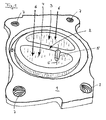
- Figure 1 shows schematically the view of a mounting flange 1 of a twin-scroll exhaust gas turbocharger.
- a first and a second exhaust gas inlet opening 3, 4 are separated from one another by a web 2.
- Radially around the exhaust gas inlet openings 3, 4 extends an annular groove 8 for receiving a sealing element, not shown.
- four mounting holes 7 are shown for mounting the exhaust gas turbocharger to an exhaust manifold of an internal combustion engine.
- the web 2 has a recess 5 according to the invention, which extends largely in the direction of a main exhaust gas flow direction 6, schematically represented by two arrows.
- the recess 5 has been produced in the present embodiment by milling, ie by machining.
- a hole can be provided directly in the web 2.
- the recess 5 has a longitudinal axis 5 'which is largely parallel to the exhaust main flow direction 6. In other Embodiments, it can also form an angle between 0 and 30 ° with the exhaust main flow direction.
- a typical size of the recess 5 according to the invention perpendicular to the longitudinal axis 5 ' is between 0.1 and 5 mm and in the direction of the longitudinal axis 5' between 0.2 and 20 mm. In this size range, the protection against the breakout of web particles has proven to be particularly effective.
- the cracking is influenced to the effect that no branches arise, which could ultimately lead to the breaking out of particles from the web 2.
- the weakening of the web cross section can be done for example by a set from above hole in the web 2 or by a laterally introduced milled into the exhaust gas bearing surface of the web. This can be one or both sides, d. H. both in the first and in the second Abgaseinströmö réelle 3, 4 done.
- the recesses 5 can be realized by mechanical processing or casting technology.
- a significant advantage of the invention is that no opening in the web 2 is formed by the measures described, which would allow a gas and pressure equalization between the two Abgaseinströmö réelleen 3, 4, which would lead to significant efficiency losses of the twin-scroll exhaust gas turbocharger.
Abstract
Description
Die Erfindung betrifft einen Twin-scroll Abgasturbolader mit den Merkmalen aus dem Oberbegriff des Patentanspruches 1.The invention relates to a twin-scroll exhaust gas turbocharger with the features of the preamble of claim 1.
Sie geht von der
Da der Steg zwischen den Abgaseinströmöffnungen eines Twin-scroll Abgasturboladers aus strömungstechnischen und thermodynamischen Gründen möglichst dünn ausgeführt werden muss, ist eine Luftkühlung, wie sie in der
Aufgabe der vorliegenden Erfindung ist es, eine Maßnahme aufzuzeigen, wie das das Ausbrechen von Partikeln aus dem Steg eines Twin-scroll Abgasturboladers verhindert werden kann.Object of the present invention is to show a measure of how the breaking of particles from the web of a twin-scroll exhaust gas turbocharger can be prevented.
Diese Aufgabe ist durch das Merkmal im kennzeichnenden Teil des Patentanspruches 1 dadurch gelöst, dass der Steg im Bereich des Befestigungsflansches eine Ausnehmung aufweist.
Auch wenn die Erfindung die Rissbildung nicht hundertprozentig verhindert, sorgt sie aber dafür, dass der Riss gezielt an einer vorbestimmten Stelle entsteht und sich nicht zur Stegwandkante hin verzweigt, wodurch Ausbrüche vermieden werden. Hierdurch ist es in vorteilhafter Weise möglich, bei höchsten Abgastemperaturen mit kostengünstigen Gusswerkstoffen auszukommen. Damit ergeben sich ganz erhebliche Kosten- und Kraftstoffverbrauchsvorteile, da ein Anfetten des Kraftstoff-/Luft-Gemisches zum Kühlen des Abgases, d. h. ein Brennkraftmaschinenbetrieb mit Kraftstoffüberschuss, entfallen kann.This object is achieved by the feature in the characterizing part of claim 1, characterized in that the web has a recess in the region of the mounting flange.
Although the invention does not completely prevent the cracking, it ensures that the crack is created specifically at a predetermined location and does not branch to the web wall edge, thereby avoiding breakouts. This makes it possible in an advantageous manner to get along with the lowest exhaust gas temperatures with inexpensive cast materials. This results in very considerable cost and fuel consumption advantages, since enrichment of the fuel / air mixture for cooling the exhaust gas, ie an internal combustion engine operation with excess fuel, can be omitted.
Die Ausgestaltungen gemäß Patentanspruch 2 stellen zwei bevorzugte Ausführungsvarianten dar.The embodiments according to
Die Fertigungsverfahren gemäß Patentanspruch 3 sind zwei bevorzugte Herstellungsverfahren für einen erfindungsgemäßen Twin-scroll Abgasturbolader. Unter spanabhebender Bearbeitung wird Bohren, Schleifen oder Fräsen verstanden, unter spanloser Fertigung Gießverfahren, wie z. B. Nieder- oder Hochdruckgießverfahren.The manufacturing methods according to
Aufgrund der Ausgestaltung gemäß Patentanspruch 4 lässt sich dieser, falls ein Riss im dem Stegbereich erfolgen sollte, gezielt in eine definierte Richtung lenken.Due to the embodiment according to claim 4, this can, if a crack should take place in the web area, direct targeted in a defined direction.
In den Patentansprüchen 5 und 6 sind besonders bevorzugte Größenordnungen für die erfindungsgemäße Ausnehmung angegeben.In the
Im Folgenden ist die Erfindung anhand eines bevorzugten Ausführungsbeispieles in einer einzigen Figur näher erläutert.In the following the invention with reference to a preferred embodiment in a single figure is explained in more detail.
Figur 1 zeigt schematisch den Blick auf einen Befestigungsflansch 1 eines Twin-scroll Abgasturboladers. Mittig im Flansch befinden sich eine erste und eine zweite Abgaseinströmöffnung 3, 4. Die erste und die zweite Abgaseinströmöffnung 3, 4 sind durch einen Steg 2 voneinander getrennt. Radial um die Abgaseinströmöffnungen 3, 4 erstreckt sich eine Ringnut 8 zur Aufnahme eines nicht dargestellten Dichtelementes. Im Randbereich des Befestigungsflansches 1 sind vier Befestigungsbohrungen 7 zur Montage des Abgasturboladers an einen Abgaskrümmer einer Brennkraftmaschine dargestellt.Figure 1 shows schematically the view of a mounting flange 1 of a twin-scroll exhaust gas turbocharger. In the middle of the flange there are a first and a second exhaust gas inlet opening 3, 4. The first and the second exhaust gas inlet opening 3, 4 are separated from one another by a
Der Steg 2 weist eine erfindungsgemäße Ausnehmung 5 auf, die sich weitgehend in Richtung einer Abgashauptströmrichtung 6, schematisch dargestellt durch zwei Pfeile, erstreckt. Die Ausnehmung 5 ist im vorliegenden Ausführungsbeispiel durch Ausfräsen, d. h. durch spanabhebende Bearbeitung erzeugt worden. In weiteren Ausführungsbeispielen kann anstelle einer Ausklinkung in einer abgasführenden Oberfläche im Flanschbereich auch eine Bohrung direkt in den Steg 2 vorgesehen werden. Die Ausnehmung 5 weist im vorliegenden Ausführungsbeispiel eine Längsachse 5' auf, die zu der Abgashauptströmrichtung 6 weitgehend parallel ausgebildet ist. In anderen Ausführungsbeispielen kann sie mit der Abgashauptströmrichtung auch einen Winkel zwischen 0 und 30° bilden. Eine typische Größe der erfindungsgemäßen Ausnehmung 5 senkrecht zur Längsachse 5' beträgt zwischen 0,1 und 5 mm und in Richtung der Längsachse 5' zwischen 0,2 und 20 mm. In diesem Größenbereich hat sich der Schutz vor dem Ausbrechen von Stegteilchen als besonders wirksam herausgestellt.The
Aufgrund der erfindungsgemäßen Ausgestaltung, durch eine örtlich begrenzte Schwächung des Steges 2, wird die Rissbildung dahingehend beeinflusst, dass keine Verzweigungen entstehen, die letztlich zum Ausbrechen von Teilchen aus dem Steg 2 führen könnten. Die Schwächung des Stegquerschnitts kann beispielsweise durch eine von oben gesetzte Bohrung in den Steg 2 oder durch eine seitlich eingebrachte Einfräsung in die abgasführende Fläche des Steges erfolgen. Dies kann ein- oder beidseitig, d. h. sowohl in der ersten als auch in der zweiten Abgaseinströmöffnung 3, 4, geschehen. Die Ausnehmungen 5 können durch mechanische Bearbeitung oder gusstechnisch realisiert werden. Ein wesentlicher Vorteil der Erfindung ist, dass durch die beschriebenen Maßnahmen keine Öffnung in dem Steg 2 entsteht, die einen Gas- und Druckausgleich zwischen den beiden Abgaseinströmöffnungen 3, 4 ermöglichen würde, was zu deutlichen Wirkungsgradverlusten des Twin-scroll Abgasturboladers führen würde.Due to the inventive design, by a localized weakening of the
Zusammengefasst kann festgestellt werden, dass durch die Erfindung die Rissbildung im Steg 2 zwar nicht hundertprozentig verhindert ist, sie sorgt aber dafür, dass ein möglicher Riss gezielt an einer vorbestimmten Stelle entsteht und sich zur Stegwandkante hin nicht verzweigt, wodurch Ausbrüche aus dem Steg 2 und somit die Zerstörung des Twin-scroll Abgasturboladers vermieden werden. Hierdurch ist es in vorteilhafter Weise möglich, bei höchsten Abgastemperaturen mit kostengünstigen Gusswerkstoffen auszukommen. Somit ergeben sich erhebliche Kosten- und Kraftstoffverbrauchsvorteile.In summary, it can be stated that, although the crack formation in the
- 1.1.
- Befestigungsflanschmounting flange
- 2.Second
- Stegweb
- 3.Third
- erste Abgaseinströmöffnungfirst exhaust gas inlet opening
- 4.4th
- zweite Abgaseinströmöffnungsecond exhaust gas inlet opening
- 5.5th
- Ausnehmungrecess
- 5'5 '
- Längsachselongitudinal axis
- 6.6th
- AbgashauptströmrichtungAbgashauptströmrichtung
- 7.7th
- Befestigungsbohrungmounting hole
- 8.8th.
- Ringnutring groove
Claims (6)
dadurch gekennzeichnet, dass der Steg (2) im Bereich des Befestigungsflansches (1) eine Ausnehmung (5) aufweist.Twin-scroll turbocharger having a first and a second, adjacent to each other, in the region of a mounting flange (1) of a web (2) separated Abgaseinströmöffnung (3, 4),
characterized in that the web (2) in the region of the mounting flange (1) has a recess (5).
dadurch gekennzeichnet, dass die Ausnehmung (5) eine Bohrung in den Steg (2) oder eine Ausklinkung an einer abgasführenden Oberfläche ist.Twin-scroll exhaust gas turbocharger according to claim 1,
characterized in that the recess (5) is a bore in the web (2) or a notch on an exhaust gas-carrying surface.
dadurch gekennzeichnet, dass die Ausnehmung (5) spanend oder spanlos gefertigt ist.Twin-scroll exhaust gas turbocharger according to claim 1 or 2,
characterized in that the recess (5) is made by machining or cutting.
dadurch gekennzeichnet, dass eine Längsachse (5') der Ausnehmung (5) einen Winkel zwischen 0° und 30° bezüglich einer Abgashauptströmrichtung (6) bildet.Twin-scroll exhaust gas turbocharger according to one of the claims 1 to 3,
characterized in that a longitudinal axis (5 ') of the recess (5) forms an angle between 0 ° and 30 ° with respect to a main exhaust gas flow direction (6).
dadurch gekennzeichnet, dass die Ausnehmung (5) weitgehend senkrecht zur Längsachse (5') eine Breite zwischen 0,1 und 5 mm aufweist.Twin-scroll exhaust gas turbocharger according to one of the claims 1 to 4,
characterized in that the recess (5) has a width between 0.1 and 5 mm substantially perpendicular to the longitudinal axis (5 ').
dadurch gekennzeichnet, dass die Ausnehmung (5) in Richtung der Längsachse (5') eine Länge zwischen 0,2 und 20 mm aufweist.Twin-scroll exhaust gas turbocharger according to one of the claims 1 to 5,
characterized in that the recess (5) in the direction of the longitudinal axis (5 ') has a length between 0.2 and 20 mm.
Applications Claiming Priority (1)
| Application Number | Priority Date | Filing Date | Title |
|---|---|---|---|
| DE102006002130A DE102006002130A1 (en) | 2006-01-17 | 2006-01-17 | Twin-scroll turbocharger |
Publications (2)
| Publication Number | Publication Date |
|---|---|
| EP1808583A2 true EP1808583A2 (en) | 2007-07-18 |
| EP1808583A3 EP1808583A3 (en) | 2013-08-28 |
Family
ID=38093435
Family Applications (1)
| Application Number | Title | Priority Date | Filing Date |
|---|---|---|---|
| EP06025040.4A Ceased EP1808583A3 (en) | 2006-01-17 | 2006-12-04 | Twin-scroll turbocharger |
Country Status (2)
| Country | Link |
|---|---|
| EP (1) | EP1808583A3 (en) |
| DE (1) | DE102006002130A1 (en) |
Cited By (1)
| Publication number | Priority date | Publication date | Assignee | Title |
|---|---|---|---|---|
| US20190353079A1 (en) * | 2018-05-16 | 2019-11-21 | GM Global Technology Operations LLC | J-groove for crack suppression |
Families Citing this family (2)
| Publication number | Priority date | Publication date | Assignee | Title |
|---|---|---|---|---|
| DE102008031724A1 (en) | 2008-07-04 | 2010-01-07 | Bayerische Motoren Werke Aktiengesellschaft | Twin-scroll turbocharger for an internal combustion engine |
| DE102014220569A1 (en) * | 2014-10-10 | 2016-04-14 | Ford Global Technologies, Llc | Charged internal combustion engine with double-flow turbine and grouped cylinders |
Citations (2)
| Publication number | Priority date | Publication date | Assignee | Title |
|---|---|---|---|---|
| JPS63198715A (en) | 1987-02-12 | 1988-08-17 | Toyota Motor Corp | Cooling device for exhaust manifold |
| DE102004005462A1 (en) | 2004-02-04 | 2005-06-16 | Audi Ag | Multi-flow housing for turbine of exhaust gas turbocharger of internal combustion engine has partition cast on wall of housing and in inlet flow direction of exhaust gas is split via small expansion gap |
Family Cites Families (3)
| Publication number | Priority date | Publication date | Assignee | Title |
|---|---|---|---|---|
| US4188784A (en) * | 1976-10-26 | 1980-02-19 | Chrysler Corporation | Articulated exhaust system |
| DE2850614C2 (en) * | 1978-11-22 | 1980-11-20 | Volkswagenwerk Ag, 3180 Wolfsburg | Thermally stressable component in the manner of a wall or a web, in particular an intermediate wall in a multi-flow pipe of an exhaust system |
| DE2916030C2 (en) * | 1979-04-20 | 1981-05-21 | Volkswagenwerk Ag, 3180 Wolfsburg | Thermally stressed pipe-like component, in particular the exhaust manifold of an internal combustion engine |
-
2006
- 2006-01-17 DE DE102006002130A patent/DE102006002130A1/en not_active Withdrawn
- 2006-12-04 EP EP06025040.4A patent/EP1808583A3/en not_active Ceased
Patent Citations (2)
| Publication number | Priority date | Publication date | Assignee | Title |
|---|---|---|---|---|
| JPS63198715A (en) | 1987-02-12 | 1988-08-17 | Toyota Motor Corp | Cooling device for exhaust manifold |
| DE102004005462A1 (en) | 2004-02-04 | 2005-06-16 | Audi Ag | Multi-flow housing for turbine of exhaust gas turbocharger of internal combustion engine has partition cast on wall of housing and in inlet flow direction of exhaust gas is split via small expansion gap |
Cited By (3)
| Publication number | Priority date | Publication date | Assignee | Title |
|---|---|---|---|---|
| US20190353079A1 (en) * | 2018-05-16 | 2019-11-21 | GM Global Technology Operations LLC | J-groove for crack suppression |
| CN110500166A (en) * | 2018-05-16 | 2019-11-26 | 通用汽车环球科技运作有限责任公司 | For inhibiting the J-shaped slot of crackle |
| US10753266B2 (en) * | 2018-05-16 | 2020-08-25 | GM Global Technology Operations LLC | J-groove for crack suppression |
Also Published As
| Publication number | Publication date |
|---|---|
| EP1808583A3 (en) | 2013-08-28 |
| DE102006002130A1 (en) | 2007-08-02 |
Similar Documents
| Publication | Publication Date | Title |
|---|---|---|
| DE102010022948B4 (en) | Internal combustion engine with direct cooling of cylinder components | |
| AT506473B1 (en) | CYLINDER HEAD OF AN INTERNAL COMBUSTION ENGINE | |
| DE60201467T2 (en) | Gas turbine combustor made of composite material with ceramic matrix | |
| EP1733132B1 (en) | Water-cooled cylinder head for a multi-cylinder internal combustion engine | |
| DE102007048666A1 (en) | Twin-scroll turbocharger | |
| EP1999362B1 (en) | Arrangement with a protected turbocharger in the exhaust gas recirculation line | |
| EP1884647B1 (en) | Liquid-cooled cylinder head for a combustion engine | |
| EP1573190B1 (en) | Cylinder head of an internal combustion engine having a camshaft bearing rail | |
| EP1428983A1 (en) | Exhaust gas turbine casing | |
| DE102016122045B4 (en) | WASTEGATE and ENGINE ASSEMBLY and method of operating an engine | |
| DE102005037384A1 (en) | Internal combustion engine with at least two cylinders has first coolant channel connected to second coolant channel in bridge region between cylinders by at least one bore so as to pass coolant | |
| CH706777A2 (en) | System with at least one turbine blade and method of placing a porous insert in a recess of a turbine blade. | |
| EP1808583A2 (en) | Twin-scroll turbocharger | |
| EP0826871B1 (en) | Cast cylinder head for a multi-cylinder combustion engine | |
| DE102013106748A1 (en) | Improved mixing for exhaust gas recirculation | |
| EP2676005B1 (en) | Exhaust turbocharger for an internal combustion engine | |
| DE3521058C2 (en) | ||
| EP2333277B1 (en) | Exhaust manifold for a combustion engine | |
| AT522271B1 (en) | COMBUSTION ENGINE WITH AT LEAST ONE CYLINDER | |
| EP1878893A1 (en) | Exhaust gas turbo charger assembly | |
| DE3615018C1 (en) | Valve stem guide for an exhaust valve | |
| EP1752643A1 (en) | Internal combustion engine with at least two cylinders | |
| EP3034837B1 (en) | Coolant air supply device for a gas turbine | |
| DE102010036392B4 (en) | Liquid-cooled cylinder head for an internal combustion engine | |
| DE102016121555B4 (en) | Multi-cylinder internal combustion engine with liquid-cooled exhaust gas turbocharger module |
Legal Events
| Date | Code | Title | Description |
|---|---|---|---|
| PUAI | Public reference made under article 153(3) epc to a published international application that has entered the european phase |
Free format text: ORIGINAL CODE: 0009012 |
|
| AK | Designated contracting states |
Kind code of ref document: A2 Designated state(s): AT BE BG CH CY CZ DE DK EE ES FI FR GB GR HU IE IS IT LI LT LU LV MC NL PL PT RO SE SI SK TR |
|
| AX | Request for extension of the european patent |
Extension state: AL BA HR MK YU |
|
| PUAL | Search report despatched |
Free format text: ORIGINAL CODE: 0009013 |
|
| AK | Designated contracting states |
Kind code of ref document: A3 Designated state(s): AT BE BG CH CY CZ DE DK EE ES FI FR GB GR HU IE IS IT LI LT LU LV MC NL PL PT RO SE SI SK TR |
|
| AX | Request for extension of the european patent |
Extension state: AL BA HR MK RS |
|
| 17P | Request for examination filed |
Effective date: 20140111 |
|
| RBV | Designated contracting states (corrected) |
Designated state(s): AT BE BG CH CY CZ DE DK EE ES FI FR GB GR HU IE IS IT LI LT LU LV MC NL PL PT RO SE SI SK TR |
|
| 17Q | First examination report despatched |
Effective date: 20140311 |
|
| AKX | Designation fees paid |
Designated state(s): AT BE BG CH CY CZ DE DK EE ES FI FR GB GR HU IE IS IT LI LT LU LV MC NL PL PT RO SE SI SK TR |
|
| RAP1 | Party data changed (applicant data changed or rights of an application transferred) |
Owner name: BAYERISCHE MOTOREN WERKE AKTIENGESELLSCHAFT |
|
| STAA | Information on the status of an ep patent application or granted ep patent |
Free format text: STATUS: THE APPLICATION HAS BEEN REFUSED |
|
| 18R | Application refused |
Effective date: 20150130 |