EP1808552A2 - Claw for crosspiece - Google Patents
Claw for crosspiece Download PDFInfo
- Publication number
- EP1808552A2 EP1808552A2 EP07398001A EP07398001A EP1808552A2 EP 1808552 A2 EP1808552 A2 EP 1808552A2 EP 07398001 A EP07398001 A EP 07398001A EP 07398001 A EP07398001 A EP 07398001A EP 1808552 A2 EP1808552 A2 EP 1808552A2
- Authority
- EP
- European Patent Office
- Prior art keywords
- claw
- profile
- crosspiece
- interior
- auto
- Prior art date
- Legal status (The legal status is an assumption and is not a legal conclusion. Google has not performed a legal analysis and makes no representation as to the accuracy of the status listed.)
- Withdrawn
Links
Images


Classifications
-
- E—FIXED CONSTRUCTIONS
- E04—BUILDING
- E04G—SCAFFOLDING; FORMS; SHUTTERING; BUILDING IMPLEMENTS OR AIDS, OR THEIR USE; HANDLING BUILDING MATERIALS ON THE SITE; REPAIRING, BREAKING-UP OR OTHER WORK ON EXISTING BUILDINGS
- E04G7/00—Connections between parts of the scaffold
- E04G7/02—Connections between parts of the scaffold with separate coupling elements
- E04G7/06—Stiff scaffolding clamps for connecting scaffold members of common shape
- E04G7/24—Couplings involving arrangements covered by more than one of the subgroups E04G7/08, E04G7/12, E04G7/20, E04G7/22
-
- E—FIXED CONSTRUCTIONS
- E04—BUILDING
- E04G—SCAFFOLDING; FORMS; SHUTTERING; BUILDING IMPLEMENTS OR AIDS, OR THEIR USE; HANDLING BUILDING MATERIALS ON THE SITE; REPAIRING, BREAKING-UP OR OTHER WORK ON EXISTING BUILDINGS
- E04G7/00—Connections between parts of the scaffold
- E04G7/02—Connections between parts of the scaffold with separate coupling elements
- E04G7/06—Stiff scaffolding clamps for connecting scaffold members of common shape
- E04G7/22—Stiff scaffolding clamps for connecting scaffold members of common shape for scaffold members in end-to-side relation
Definitions
- This document describes a claw for crosspiece to be used in the crosspiece setting in mobile working towers made of pre-fabricated elements (modular system).
- the simple rabbet systems (a) are easy to assemble, can be slightly trusted, work only by pressure rabbet, but can be freed easily by accidental actions or by verified movements/vibrations in the towers during the works.
- the setting methods referred in (b) and (c), of the anterior paragraph have as main inconvenience the assembly and dissemble problem, which is complicated and delayed, because, besides the cramps, wedges or rods, it is necessary other accessories for the assembly, such as (screws, nuts, etc.), which also involves using squeezing and relief tools.
- the assembly and dissemble of these towers have inevitable man power costs associated to the necessity of assembly/dissemble other braking elements.
- This new claw for crosspiece resolves totally all the anterior referred problems, because since its elements were technically studied, with optimised configuration and functioning, it allows an easy, rapid, resistant and safe assembly, dismount and reconfiguration of the mobile working towers made of pre-fabricated elements, easily adapted to modular systems.
- This claw for crosspiece is introduced in the extremities of the crosspiece and fixed with a rivet, all being part of the crosspiece set, including the profile and the claws.
- the geometric configuration of the Claw body for the Crosspiece is easily adapted to be equal to the profile periphery used in the crosspiece and in the mobile working towers elements build with pre-fabricated elements. The following profiles are dependent of the used geometrical configuration:
- the setting of the claw presents characteristics for the working towers installation placed outside, exposed to the environment conditions (atmospheric agents, polluting agents, etc.).
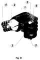
- the claw for the crosspiece presents itself with two differentiated safety elements, the Automotive Mobile Element (3) and the Safety Latch (2). Both were studied with the main purpose to restrict unnecessary access, to control and to prevent accidental actions in the structure crosspiece setting system. Only the movements of these two elements permit alternating between the "open” positions, for the assembly, and the "close” positions, for situations of concluded assembly.
- the opening of the automotive latch system (3) is influenced by two buttons simultaneously (5). With simple and rapid actions and without the use of complementary accessories, the crosspiece is assembled in the structure and fixed with high security.
- the Mobile Automotive Element (3) moves in rotation around an axle (6); the buttons (5) are fixed by an elastic peg (7 fig. 6) and the cradle for the spring (8 fig. 6) has as main function the movement that blocks and unblocks, allowing the open and close positions.
- the Safety Latch (2 fig. 6) comprises a spring (10 fig. 6) and a guide bolt (11) that helps the element to maintain its opening and closing positions.
- This Security lock is fixed by forging elements, since the ring function (9) and the bearing function (12) permits forging the Latch without its immobilization, in other words, they permit the rotation movements.
Landscapes
- Engineering & Computer Science (AREA)
- Architecture (AREA)
- Mechanical Engineering (AREA)
- Civil Engineering (AREA)
- Structural Engineering (AREA)
- Connection Of Plates (AREA)
- Body Structure For Vehicles (AREA)
Abstract
Description
- This document describes a claw for crosspiece to be used in the crosspiece setting in mobile working towers made of pre-fabricated elements (modular system).
- Generally, the various crosspiece setting systems existing in the market that are used in mobile working towers, are composed by simple rabbet elements and by setting cramps. Therefore, when a working tower is assembled with a certain composition and configuration in a certain local, and that it needs reconfiguration; local alteration or give other functionality to the tower, the dissemble option and the new assembly is considered a problem by the time and the involved ways.
- In the crosspiece setting systems, there are two predominance types of settings:
- (a) Simple rabbet elements, with the use of wedges or brakes.
- (b) Crosspiece setting systems to the working tower elements, with the use of cramps or direct screwing.
- (c) Mixed systems that use the two anterior methods simultaneously or with similar adaptations.
- The simple rabbet systems (a) are easy to assemble, can be slightly trusted, work only by pressure rabbet, but can be freed easily by accidental actions or by verified movements/vibrations in the towers during the works.
- The setting methods referred in (b) and (c), of the anterior paragraph, have as main inconvenience the assembly and dissemble problem, which is complicated and delayed, because, besides the cramps, wedges or rods, it is necessary other accessories for the assembly, such as (screws, nuts, etc.), which also involves using squeezing and relief tools. The assembly and dissemble of these towers have inevitable man power costs associated to the necessity of assembly/dissemble other braking elements.
- This new claw for crosspiece that is now presented, resolves totally all the anterior referred problems, because since its elements were technically studied, with optimised configuration and functioning, it allows an easy, rapid, resistant and safe assembly, dismount and reconfiguration of the mobile working towers made of pre-fabricated elements, easily adapted to modular systems.
- This claw for crosspiece is introduced in the extremities of the crosspiece and fixed with a rivet, all being part of the crosspiece set, including the profile and the claws.
The geometric configuration of the Claw body for the Crosspiece is easily adapted to be equal to the profile periphery used in the crosspiece and in the mobile working towers elements build with pre-fabricated elements. The following profiles are dependent of the used geometrical configuration: - (a) The expanded extension (4) with the structural periphery adapted to the crosspiece profile interior configuration is rebated at the extremity and braked with a rivet (14 fig. 2). This claw has an angle of nearly 45º to apply in the crosspiece brake but, with the changing of the angle for 90º, there it be applied in the braking horizontal crosspiece of the mobile towers structure.
- (b) The claw interior area (16 fig. 4) will have a contour equivalent to the profile (13 fig. 4) used in the element to which it adjusts with compatible tolerance.
- (c) The auto-positioning bolt (1) holding the claw body, enters the profile interior used as an element step, guides & supports the claw.
- The setting of the claw presents characteristics for the working towers installation placed outside, exposed to the environment conditions (atmospheric agents, polluting agents, etc.).
- Any of latch elements will only be set in motion (locked/unlocked) by mechanical movements of the safety elements that constitute this setting claw.
- The claw for the crosspiece presents itself with two differentiated safety elements, the Automotive Mobile Element (3) and the Safety Latch (2). Both were studied with the main purpose to restrict unnecessary access, to control and to prevent accidental actions in the structure crosspiece setting system. Only the movements of these two elements permit alternating between the "open" positions, for the assembly, and the "close" positions, for situations of concluded assembly. The opening of the automotive latch system (3) is influenced by two buttons simultaneously (5). With simple and rapid actions and without the use of complementary accessories, the crosspiece is assembled in the structure and fixed with high security.
- The Mobile Automotive Element (3) moves in rotation around an axle (6); the buttons (5) are fixed by an elastic peg (7 fig. 6) and the cradle for the spring (8 fig. 6) has as main function the movement that blocks and unblocks, allowing the open and close positions.
- The Safety Latch (2 fig. 6) comprises a spring (10 fig. 6) and a guide bolt (11) that helps the element to maintain its opening and closing positions. This Security lock is fixed by forging elements, since the ring function (9) and the bearing function (12) permits forging the Latch without its immobilization, in other words, they permit the rotation movements.
- With the main purpose to understand more easily not only its composition but also the use of this invention, a brief functioning description will be followed, through an assembly example and drawings references. Image 3 - front sight lateral vertical projection, image 4 - steps sight horizontal projection (15) and element profile cut (13) before the claw junction, supposedly applied in the crosspiece extremity (not visible in the drawing) but would be rabbet in the extension (4) of the claw body, being this a mere example and never limited, where:
- 1º) Press simultaneously both buttons (5 figs 1 and 2) in order to open the automatic security mobile element (3 figs 1 and 3).
- 2º) Line up the auto-positioning Claw bolt (1 figs1 and 4) along with the perforated step (15 fig. 4) of the element (13).
- 3º) Displace the Claw in the direction of the step hole (15 fig. 4). When arriving to the final position, the automatism closes the mobile element (3) and the Claw stays automatically fixed.
- 4º) Rotate the safety latch (2 fig. 5) in front of the element profile (13), closing position, which compels to a perfect coupling of the element profile (13 fig. 5) in the claw interior area.
- 5º) To remove the Claw:
- Rotate the safety lock (2 fig. 3) in order stay away from the element profile (13);
- Press simultaneously the buttons (5) to open the automatic security system and pull the claw.
-
- 1-
- Auto-positioning bolt that will rabbet in the element step
- 2-
- Complementary safety latch
- 3-
- Mobile element of the automatic safety latch
- 4-
- Structural claw extension to apply in the crosspiece
- 5-
- Pressure buttons synchronized for automatic opening
- 6-
- Axle of the automatic security components
- 7-
- Elastic peg
- 8-
- Cradle for the mobile element spring
- 9-
- Ring
- 10-
- Spring for automatic safety latch
- 11-
- Guide bolt for safety latch
- 12-
- Bearing
- 13-
- Element Profile
- 14-
- Location of the linking rivet application and joined claw to the crosspiece
- 15-
- Element profile of the step
- 16-
- Periphery contour of the claw interior
Claims (1)
- CLAW FOR CROSSPIECE to be used in mobile working towers made of pre-fabricated elements or modular system that are characterized by presenting in the claw interior a auto-positioning guide bolt (1), automatic closing and opening systems (3) that only opens with simultaneous pressure of the two buttons (5), a second security system (2) which is manual and only closes when the claw is duly applied in the element. The claw is applied in the crosspiece profile exterior extremity by the extension rabbet (4) being this joined and forged to the profile. The claw interior area (16) is adequate with the periphery contour and equivalent to the element profile where it is applied and the guide bolt (1) has exterior periphery equivalent to the interior step profile format of the element where it is applied. The auto-positioning bolt (1) and the opening/close system (3) allow the assembly/dissemble to an easy and rapid reconfiguration without neither tools nor accessories.
Applications Claiming Priority (1)
| Application Number | Priority Date | Filing Date | Title |
|---|---|---|---|
| PT10341806A PT103418B (en) | 2006-01-12 | 2006-01-12 | CLAY FOR LOCK |
Publications (2)
| Publication Number | Publication Date |
|---|---|
| EP1808552A2 true EP1808552A2 (en) | 2007-07-18 |
| EP1808552A3 EP1808552A3 (en) | 2011-06-08 |
Family
ID=37964902
Family Applications (1)
| Application Number | Title | Priority Date | Filing Date |
|---|---|---|---|
| EP07398001A Withdrawn EP1808552A3 (en) | 2006-01-12 | 2007-01-04 | Claw for crosspiece |
Country Status (2)
| Country | Link |
|---|---|
| EP (1) | EP1808552A3 (en) |
| PT (1) | PT103418B (en) |
Cited By (2)
| Publication number | Priority date | Publication date | Assignee | Title |
|---|---|---|---|---|
| GB2498963A (en) * | 2012-02-01 | 2013-08-07 | Turner Access Ltd | Scaffolding component fastener |
| EP3670785A1 (en) * | 2018-12-21 | 2020-06-24 | Peri Gmbh | Connection head for the tube profile of a modular component in the form of a vertical diagonal and vertical diagonal |
Family Cites Families (2)
| Publication number | Priority date | Publication date | Assignee | Title |
|---|---|---|---|---|
| US4715474A (en) * | 1986-07-14 | 1987-12-29 | Wehmeyer Donald T | Scaffold system |
| FR2799783B1 (en) * | 1999-10-18 | 2002-01-04 | Tubesca Sa | DEVICE FOR FIXING DIAGONAL BARS ON SCAFFOLDING LADDERS AND SCAFFOLDING OBTAINED |
-
2006
- 2006-01-12 PT PT10341806A patent/PT103418B/en not_active IP Right Cessation
-
2007
- 2007-01-04 EP EP07398001A patent/EP1808552A3/en not_active Withdrawn
Cited By (5)
| Publication number | Priority date | Publication date | Assignee | Title |
|---|---|---|---|---|
| GB2498963A (en) * | 2012-02-01 | 2013-08-07 | Turner Access Ltd | Scaffolding component fastener |
| GB2498963B (en) * | 2012-02-01 | 2018-02-14 | Turner Access Ltd | Scaffolding component fastener |
| EP3670785A1 (en) * | 2018-12-21 | 2020-06-24 | Peri Gmbh | Connection head for the tube profile of a modular component in the form of a vertical diagonal and vertical diagonal |
| CN111350344A (en) * | 2018-12-21 | 2020-06-30 | Peri有限公司 | Connector of pipe section of modularized scaffold assembly used as vertical diagonal member and vertical diagonal member |
| CN111350344B (en) * | 2018-12-21 | 2022-11-11 | Peri有限公司 | Connector for pipe section of vertical diagonal member and vertical diagonal member |
Also Published As
| Publication number | Publication date |
|---|---|
| PT103418A (en) | 2007-07-31 |
| PT103418B (en) | 2007-11-05 |
| EP1808552A3 (en) | 2011-06-08 |
Similar Documents
| Publication | Publication Date | Title |
|---|---|---|
| EP2247342A1 (en) | Fall protection rail and fall protection method | |
| WO2005069830A3 (en) | A fastner installaton system | |
| KR20140143068A (en) | Quick safety coupler having advanced structured automatic immersing device therein | |
| US7168670B2 (en) | Quick ceiling fan housing and canopy installation assembly | |
| JP6591215B2 (en) | Safety handrails in tight-type scaffolding | |
| EP3231697A1 (en) | Locking device for pedal vehicles | |
| CN103375075A (en) | Electromagnetic locking device for automatic door | |
| CN105370126A (en) | Semi-automatic pilot pin door hinge | |
| KR20170034742A (en) | A advanced functional quick coupler system and its device | |
| CN104453450A (en) | Intelligent express interim cabinet | |
| GB2387874A (en) | Anchor apparatus | |
| CN204754739U (en) | Ascending stair cohesion device | |
| CN104937201B (en) | Adjustable hinge | |
| EP2657436B1 (en) | Fixing arrangement for door fitting | |
| CN202879651U (en) | Integral device for white car body car door lifting device | |
| PT103418B (en) | CLAY FOR LOCK | |
| JP2000053351A (en) | Curing device for elevator hall opening | |
| KR20120068669A (en) | Ventilator maintenance door | |
| CN218759261U (en) | Novel fireproof lock | |
| CN218912575U (en) | Limiting device for casement window | |
| JPH0581518B2 (en) | ||
| CN110341815A (en) | A kind of escape driver's cabin and vehicle | |
| CN219528483U (en) | Pile hole wellhead protecting cover | |
| KR20190138929A (en) | Bus emergency escape ladder | |
| JP7032482B2 (en) | Operation device for temporary scaffolding |
Legal Events
| Date | Code | Title | Description |
|---|---|---|---|
| PUAI | Public reference made under article 153(3) epc to a published international application that has entered the european phase |
Free format text: ORIGINAL CODE: 0009012 |
|
| AK | Designated contracting states |
Kind code of ref document: A2 Designated state(s): AT BE BG CH CY CZ DE DK EE ES FI FR GB GR HU IE IS IT LI LT LU LV MC NL PL PT RO SE SI SK TR |
|
| AX | Request for extension of the european patent |
Extension state: AL BA HR MK YU |
|
| PUAL | Search report despatched |
Free format text: ORIGINAL CODE: 0009013 |
|
| AK | Designated contracting states |
Kind code of ref document: A3 Designated state(s): AT BE BG CH CY CZ DE DK EE ES FI FR GB GR HU IE IS IT LI LT LU LV MC NL PL PT RO SE SI SK TR |
|
| AX | Request for extension of the european patent |
Extension state: AL BA HR MK RS |
|
| AKX | Designation fees paid |
Designated state(s): AT BE BG CH CY CZ DE DK EE ES FI FR GB GR HU IE IS IT LI LT LU LV MC NL PL PT RO SE SI SK TR |
|
| STAA | Information on the status of an ep patent application or granted ep patent |
Free format text: STATUS: THE APPLICATION IS DEEMED TO BE WITHDRAWN |
|
| 18D | Application deemed to be withdrawn |
Effective date: 20111209 |