EP1806914A1 - Information processing method and information processing apparatus - Google Patents
Information processing method and information processing apparatus Download PDFInfo
- Publication number
- EP1806914A1 EP1806914A1 EP07100098A EP07100098A EP1806914A1 EP 1806914 A1 EP1806914 A1 EP 1806914A1 EP 07100098 A EP07100098 A EP 07100098A EP 07100098 A EP07100098 A EP 07100098A EP 1806914 A1 EP1806914 A1 EP 1806914A1
- Authority
- EP
- European Patent Office
- Prior art keywords
- space
- data
- color
- section
- information processing
- Prior art date
- Legal status (The legal status is an assumption and is not a legal conclusion. Google has not performed a legal analysis and makes no representation as to the accuracy of the status listed.)
- Granted
Links
Images


Classifications
-
- H—ELECTRICITY
- H04—ELECTRIC COMMUNICATION TECHNIQUE
- H04N—PICTORIAL COMMUNICATION, e.g. TELEVISION
- H04N1/00—Scanning, transmission or reproduction of documents or the like, e.g. facsimile transmission; Details thereof
- H04N1/46—Colour picture communication systems
- H04N1/56—Processing of colour picture signals
- H04N1/60—Colour correction or control
- H04N1/603—Colour correction or control controlled by characteristics of the picture signal generator or the picture reproducer
- H04N1/6033—Colour correction or control controlled by characteristics of the picture signal generator or the picture reproducer using test pattern analysis
Definitions
- the present invention relates to an information processing method, information processing apparatus, program and medium of an image forming apparatus such as a color printer.
- An image quality evaluation method of output images of image forming apparatuses such as printers are divided into a psychological evaluation that evaluates the degree perceived by vision, and a physical evaluation that evaluates by objectively measuring values of properties of image structures. As one of the important factors of the image quality, there is gradation of an image.
- a method of obtaining a "distinguished gray scale" which divides the density range of a patch image, in which a pixel value has a fixed area separated apart at fixed intervals, by twice the RMS granularity (it will be called conventional technique 1).
- the algorithm of the conventional technique 1 can calculate the distinguished gray scale of a printer, it cannot evaluate an image such as a gradation image whose color or lightness continuously changes from shadow to highlight. Even if the interval is made small of the input pixel values of the patches used for calculating the distinguished gray scale, accurate gradation evaluation cannot be achieved because of the following reasons.
- Japanese patent application laid-open No. 11-25274/1999 discloses an image evaluation method of such a kind (called conventional technique 2 from now on).
- the method using at least one of the optical information items including the lightness information and density information on the image output, calculates the difference between the optical information items on adjacent gray levels, thereby objectively evaluating gradation characteristics of the output apparatus.
- the gradation evaluation is not performed for all the gradations distributed three-dimensionally, but is carried out only along one axis of the lightness or density.
- the evaluation values can be calculated, their feedback cannot be performed directly.
- an object of the present invention to provide an information processing method, information processing apparatus, program and medium capable of solving the foregoing problems.
- an information processing apparatus for a data converting section for converting data of a first color space to data of a second color space
- said information processing apparatus comprising: patch image generating section for resolving the first color space into a plurality of steps, and for generating, by using said data converting section, patch image data composed of color data in the second color space corresponding to color data of the individual steps after resolving; output section for outputting onto a recording medium a patch image corresponding to the patch image data generated; colorimetric section for carrying out colorimetry of the patch image output onto the recording medium by said output section, and for outputting measured data in a third color space independent of the first color space and the second color space; evaluation reference space generating section for extracting reference point data from the measured data output, and for calculating, by using the reference point data, coordinate data of spatial distribution points corresponding to an evaluation reference in the third color space corresponding to a remainder of the measured data; and color separation evaluation value calculating section for calculating color separation
- an information processing method for a data converting section for converting data of a first color space to data of a second color space comprising: a patch image generating step of resolving the first color space into a plurality of steps, and of generating, by using said data converting section, patch image data composed of color data in the second color space corresponding to color data of the individual steps after resolving; an output step of outputting, by output section, onto a recording medium a patch image corresponding to the patch image data generated; a colorimetric step of carrying out colorimetry of the patch image output onto the recording medium by said output section, and of outputting measured data in a third color space independent of the first color space and the second color space; an evaluation reference space generating step of extracting reference point data from the measured data output, and of calculating, by using the reference point data, coordinate data of spatial distribution points corresponding to an evaluation reference in the third color space corresponding to a remainder of the measured data; and
- an information processing method for calculating an evaluation value of a data converting section for converting data of a first color space to data of a second color space, said information processing method comprising: an input step of resolving the first color space into a plurality of steps, of generating, by using said data converting section, patch image data composed of color data in the second color space corresponding to color data of the individual steps after resolving, and of inputting measured data in a third color space, the measured data obtained by carrying out colorimetry of a generated patch image; an evaluation reference space generating step of extracting reference point data from the measured data, and for calculating, by using the reference point data, coordinate data of spatial distribution points corresponding to an evaluation reference in the third color space corresponding to a remainder of the measured data; and an evaluation value calculating step of calculating the evaluation value of said data converting section from differences between the measured data and the coordinate data of the spatial distribution points corresponding to the evaluation reference in the third color space calculated, the coordinate data
- the gradation evaluation can be performed on all the dimensions of a color space the data converting section has.
- the evaluation result of the data converting section can be fed back directly in the form of modification of the data converting section.
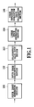
- FIG. 1 is a block diagram showing an entire configuration of a color separation evaluation system of a color printer of a first embodiment in accordance with the present invention
- FIG. 2 is a view showing an example of a color separation evaluation system in individual embodiments in accordance with the present invention
- FIG. 3 is a block diagram showing individual modules of the system shown in FIG. 2;
- FIG. 4 is a flowchart illustrating the operation of the color separation evaluation and modification of the first embodiment in accordance with the present invention
- FIG. 5 is a block diagram showing an entire configuration of a color separation evaluation system of a color printer of a second embodiment in accordance with the present invention
- FIG. 6 is a flowchart illustrating the operation of the color separation evaluation and modification of a third embodiment in accordance with the present invention.
- FIG. 7 is a block diagram showing an entire configuration of a color separation evaluation system of a color printer of the third embodiment in accordance with the present invention.
- FIG. 8 is a diagram illustrating a target point calculating method in the embodiment in accordance with the present invention.
- FIG. 9 is a diagram illustrating another target point calculating method in the embodiment in accordance with the present invention.
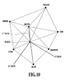
- FIG. 10 is a diagram illustrating a linear space in the embodiment in accordance with the present invention.
- FIG. 1 is a block diagram showing an entire configuration of a color separation evaluation system of a color printer of a first embodiment in accordance with the present invention.
- the color separation evaluation system of the color printer of the present embodiment comprises a patch image generating section 101, patch image colorimetric section 102, colorimetric value input section 103, linear space generating section 104, and color separation evaluation value calculating section 105.
- An LUT (lookup table) as a data converting section converts first color space data into second color space data.
- the patch image generating section 101 resolves the first color space into an arbitrary number of steps, converts them into the second color space via the LUT, and generates the patch image.
- the LUT can be composed of a memory.
- the LUT stores the data (values) for conversion in appropriate addresses of the memory in such a manner that the address bus of the memory corresponds to the input value and the data bus of the memory corresponds to the output value after the conversion, for example.
- the data input to the address causes a desired data conversion result to be output from the data bus.
- the patch image generated by the patch image generating section 101 is output onto a recording medium such as paper by a printer as an output section.
- the patch image colorimetric section 102 has a colorimeter such as a spectrophotometer.
- the patch image colorimetric section 102 carries out colorimetry of the output image on the recording medium with the colorimeter.
- the colorimetric values obtained by the colorimeter can be expressed by a third color space independent of the first color space or second color space.
- the colorimetric value input section 103 is supplied with the colorimetric values obtained by the patch image colorimetric section 102.
- the linear space generating section 104 calculates ideal spatial distribution in the color space of the LUT from the colorimetric values supplied.
- the color separation evaluation value calculating section 105 compares the ideal spatial distribution in the color space of the LUT calculated by the linear space generating section 104 with the actual measurement data of the LUT supplied from the colorimetric value input section 103, thereby calculating color separation evaluation values corresponding to the differences between the ideal values and actual measurement values according to the compared results.
- the color space of the LUT includes the first color space and second color space.
- FIG. 2 shows a color separation image processing system as an example of the embodiment in accordance with the present invention.
- the reference numeral 201 designates a spectrophotometer as a patch image colorimetric section 102.
- the reference numeral 202 designates a computer system composed of a personal computer, for example.
- the computer system 202 can acquire an image signal (colorimetric data) read by the spectrophotometer 201, carry out processing that will be described later, and store the processing results in a storing section.
- the computer system 202 can display image signal information obtained here on a display 203, or output it via a printer 204.
- FIG. 3 is a block diagram showing a main section of the configuration of FIG. 2 in blocks of functional modules.
- the reference numeral 301 designates an interface (I/F) for connecting a mouse and keyboard 313 for a user to input various manual instructions and the like to the computer system 202.
- the reference numeral 302 designates an interface (I/F) for connecting the computer system 202 with input devices such as the spectrophotometer 201.
- the reference numeral 303 designates a CPU for controlling the operation of individual internal blocks of the computer system 202, or for executing programs stored inside.
- the reference numeral 304 designates a ROM for storing the image processing program and the like necessary in advance.
- the reference numeral 305 designates a RAM for providing the CPU 303 with a work area for temporarily storing the program for the processing in the CPU 303 and image data to be processed.
- the reference numeral 306 designates a display controller for controlling the display unit 203 for displaying an image to be processed or messages to an operator.
- the reference numeral 307 designates an interface (I/F) for connecting the computer system 202 with the color printer 204.
- the reference numeral 308 designates a hard disk (HD) drive that stores in advance programs and image data to be transferred to the RAM 305, stores the image data after processing, and reads these data.
- HD hard disk
- the reference numeral 314 designates transmission equipment including a modem, network card and the like, which transmits a variety of data held in various sections of the computer system 202 to external devices, and receives a variety of data from the external devices.
- the reference numeral 309 designates an interface (I/F) for connecting the transmission equipment 314 to the computer system 202.
- the reference numeral 310 designates a CD drive which can read data stored in a CD (CD-R/CD-RW/DVD), one of the external storing media, or write data to the CD.
- the reference numeral 311 designates an FD drive which can read from or write to an FD in the same manner as the CD drive 310.
- the HD 308 can install the program or information thereon to be transferred to the RAM 305 as needed.
- the reference numeral 312 designates a sound interface (I/F) which is connected to an external line input 315 or microphone to input audio data from the outside.
- I/F sound interface
- FIG. 4 is a flowchart illustrating an operation procedure for carrying out the present embodiment in the configuration as shown in FIG. 2 and FIG. 3.
- a computer executable program describing the procedure illustrated in the flowchart of FIG. 4 is stored in the ROM 304 in advance. Alternatively, it can be stored in advance in the HD drive 308 as an external storing unit. After reading the program to the RAM 305, the CPU 303 executes the program, thereby carrying out the present embodiment.
- a printer driver (program) including an LUT, which will be described later, is stored in the HD drive 308 in advance, and is transferred to the RAM 305 when performing each embodiment.
- step S401 When the processing starts, data on a desired number of colors are obtained at step S401 by dividing elements (primary colors) of a multidimensional colorimetric system, such as RGB, XYZ and CMYK which are the components of the first color space, into a desired number of steps.
- the individual color data thus obtained are converted into the second color space data through the LUT.
- a patch image corresponding to the data (patch data) thus obtained by the conversion is output onto a recording medium by the printer 204.
- the step division is not necessarily uniform.
- the patch data can be acquired through the transmission equipment 314 such as the modem or network card capable of receiving a variety of data from the external devices.
- the steps decided and signal values (patch data) used at the patch output are stored in the RAM 305, or in the external storing unit 308 if their volume is large.
- the description will be continued as described above under the assumption that the first color space is a three-dimensional RGB space and the second color space is a CMYK space which is the primary colors of the printer.
- the second color space is variable in accordance with the number of color materials mounted on the printer 204.
- the second color space can be at least two-dimensional space, and can be a CMYKLcLm and CMRKRGB space.
- the colorimetry of the patch that is output onto the recording medium at step S401 is carried out using the spectrophotometer 201.
- the evaluation color space used for the colorimetry can be a CIEL*a*b* space or XYZ space or Jab space, which is the third color space that does not depend on the first or second color space.
- the evaluation color space although the evaluation in other multidimensional spaces is possible, the three-dimensional space is best in the present invention. It is obvious, however, that the present invention is not limited to the evaluation in the three-dimensional space.
- step S403 the colorimetric values of the individual patches passing through the colorimetry at step S402, that is, the CIEL*a*b* values are input. They are stored in the RAM 305 in connection with the signal values of the individual patches stored at step S401, or stored in the HD drive 308 if their volume is large, and proceeds to step S404.
- six primaries are extracted which consist of white dots (W), blackdots (Bk), and primary colors and secondary colors of the printer from among the relationships between the patch signal values and colorimetric values stored at step S403.
- the six primaries are cyan (C), magenta (M), yellow (Y), red (R), green (G) and blue (B).
- a solid having the individual dots (W, Bk, C, M, Y, R, G, B) as vertices is formed as shown in FIG. 10.
- planes are formed by individual lines joining the six primaries, W and Bk. On the individual planes formed, meshes are formed as will be described later in detail.
- Intersection points on the individual meshes are formed in accordance with the number of steps and their intervals determined at step S401.
- the intersection points on the individual meshes constitute target points.
- W-Bk, W-C-Bk, W-M-Bk, W-Y-Bk, W-R-Bk, W-G-Bk and W-B-Bk are control lines.
- the target points are formed as follows: As for each control line, the gradations between the vertices of which are all at least appropriate one of L* (lightness), C* (chroma) and H* (hue), individual control points are formed at linear intervals. For example, target points for W-C-Bk lines as illustrated in FIG.
- Gray control points G1-G6 are formed in such a manner as to become L* linear between W-Bk; highlight control points H1 - H6 are formed in such a manner that L* and C* each become linear between W-C; and shadow control points S1 - S6 are formed in the same manner between C-Bk. After that, as illustrated in FIG. 8, the gray control points, highlight control points and shadow control points are connected by lines to form internal target points.
- Yellow-Red control points YR1- YR6 are formed in such a manner as to become H* linear between Y-R; Yellow-Black control points YK1 - YK6 are formed in such a manner that L* and H* each become linear between Y-Bk; and Red-Black control points RK1 - RK6 are formed in the same manner between R-Bk.
- the Yellow-Red control points, Yellow-Black control points and Red-Black control points are connected by lines to form internal target points.
- the data (target points) on the L*a*b* space are formed as ideal values applicable as an evaluation reference to the individual patch data.
- the coordinate (target point) data of the individual points formed in the linear space are stored in the RAM 305, or in the HD drive 308 or the like if their volume is large.
- evaluation values of the color separation are calculated.
- the color separation evaluation values are obtained from the differences between the ideal values (target points) at the individual points in the linear space formed at step S404 and the actual measurement values input at step S403.
- the differences it is possible to employ a method using ⁇ Eab, or a method such as ⁇ E94 having the chroma direction as a denominator, or geometrical calculation.
- the calculated evaluation values can be output through the display 203, for example. Alternatively, they can be printed out, or stored in a storing medium such as a CD in the form of electronic data.
- the data for the conversion in the LUT are corrected in such a manner as to reduce the calculated differences to zero at step S406.
- three-dimensional interpolation such as cubic interpolation and tetrahedral interpolation is carried out according to the surrounding space points.
- the data after the correction are spatially calculated from the color material ground associated with the control points used as the individual interpolations.
- interpolation method employed in the spatial interpolation of the foregoing correction is not limited to the cubic interpolation or tetrahedral interpolation. A series of procedures is completed when step S406 is terminated.
- a gamma space adjusting section 501 is interposed between the linear space generating section 104 and the color separation evaluation value calculating section 105.
- the gamma space adjusting section 501 can adjust (determine) the coordinates of the target points in the L*a*b* space, which are fed from the linear space generating section 104, with providing gamma in the lightness direction.
- the solid is formed which has the vertices of the six primaries consisting of the white dot (W), black dot (Bk) and primary colors and secondary colors of the printer to form the target points in the evaluation color space
- the six primaries are cyan (C), magenta (M), yellow (Y), red (R), green (G) and blue (B), which are the primary colors and secondary colors of the printer.
- C cyan
- M magenta
- Y yellow
- R red
- G green
- blue blue
- the colorimetric values of the color separation of the following seven lines often do not exhibit linear transition in the L*a*b* space because of the characteristics of the color materials. Thus, such a configuration is also possible which considers the hue transition in forming the evaluation color space.
- W-Bk line joining the white dot (W) andblackdot (Bk) constituting the primary colors and secondary colors of the printer.
- the remainder is W-C-Bk, W-M-Bk, W-Y-Bk, W-R-Bk, W-G-Bk and W-B-Bk, which have as the vertices the six primaries constituting the primary colors and secondary colors of the printer color space.
- FIG. 7 Such a configuration is shown in FIG. 7. As shown in FIG. 7, it differs from the configuration of FIG. 5 in that a colorimetric value mapping section 701 is interposed between the linear space generating section 104 and the gamma space adjusting section 501.
- the colorimetric value mapping section 701 carries out mapping onto a linear space the spatial curves of the colorimetric values when measuring the color materials separately.
- an LUT remapping section 702 is newly added at the final stage of the processing.
- the LUT remapping section 702 carries out remapping onto the real space in the entirely inverse method to the method that carries out the mapping onto the linear space in the colorimetric value mapping section 701.
- the mapping is carried out which enables the colorimetric values of each of the printer-loaded color materials and of the W-C, W-M, W-Y, W-R, W-G and W-B composed of the secondary colors to exist in the linear space as illustrated in FIG. 10.
- geometrical conversion such as affine conversion can be used, besides any other conversions.
- step S502 the completely inverse method to that of step S501 is carried out to restore geometrically to the actual measurement space.
- the present invention is not limited to the apparatus and method for implementing the foregoing embodiments.
- a configuration is also possible that supplies the computer (CPU or MPU) in the foregoing system or apparatus with program code of software for implementing the foregoing embodiments, and the computer of the foregoing system or apparatus operates the foregoing devices in accordance with the program code.
- Such a configuration for implementing the foregoing embodiments also falls within the scope of the present invention.
- the program code itself of the software implements the functions of the foregoing embodiments.
- the program code itself, and a section for supplying the program code to the computer, that is, a storing medium that stores the program code also fall within the scope of the present invention.
- the storing medium for storing the program code it is possible to use a floppy (registered trademark) disk, hard disk, optical disk, magneto-optical disk, CD-ROM, magnetic tape, nonvolatile memory card or ROM.
- the present invention is not limited to the case where the computer satisfies the functions of the foregoing embodiments by controlling the individual devices in accordance with the program code supplied.
- the program code also falls within the scope of the present invention in the case where the program code implements the foregoing embodiments in conjunction with the OS (operating system) or other application software working on the computer.
- the program code supplied can be stored in a memory provided in an expanded board of the computer or in an expanded unit connected to the computer. After that, according to the instructions of the program code, the CPU provided in the expanded board or expanded unit executes a whole or part of the actual processing. Such a case where the processing implements the foregoing embodiments also falls within the scope of the present invention.
- a patch image generating section (101) generates a patch image by resolving the RGB space into an arbitrary number of steps, and by converting into a CMYK space via an LUT.
- a patch image colorimetric section (102) outputs the patch image onto a recording medium via a printer, and carries out colorimetry of the output image with a colorimeter.
- colorimetric values colorimetric values represented in an L*a*b* space independent of the RGB space and CMYK space are obtained.
- a linear space generating section (104) calculates ideal spatial distribution in the color space of the LUT according to the colorimetric values supplied.
- a color separation evaluation value calculating section (105) compares the ideal spatial distribution in the color space of the LUT with actual measurement data of the LUT. According to the compared results, color separation evaluation values are calculated from differences between the ideal value and actual measurement values.
Abstract
Description
- The present invention relates to an information processing method, information processing apparatus, program and medium of an image forming apparatus such as a color printer.
- An image quality evaluation method of output images of image forming apparatuses such as printers are divided into a psychological evaluation that evaluates the degree perceived by vision, and a physical evaluation that evaluates by objectively measuring values of properties of image structures. As one of the important factors of the image quality, there is gradation of an image.
- As a standard for representing the gradation physically, a method of obtaining a "distinguished gray scale" is used which divides the density range of a patch image, in which a pixel value has a fixed area separated apart at fixed intervals, by twice the RMS granularity (it will be called conventional technique 1). Although the algorithm of the
conventional technique 1 can calculate the distinguished gray scale of a printer, it cannot evaluate an image such as a gradation image whose color or lightness continuously changes from shadow to highlight. Even if the interval is made small of the input pixel values of the patches used for calculating the distinguished gray scale, accurate gradation evaluation cannot be achieved because of the following reasons. First, colors and lightness can change in accordance with printing positions because of the effect of noise superposed onto the printing regions when the printer carries out printing or of the shading characteristics of the printer. Second, using a patch image as the evaluation image presents a problem in that since the impression, which is given by an image such as a gradation image whose colors and lightness gradually vary in very small regions, differs from the impression perceived by human vision, matching is not good between the evaluation values. - To solve the problem, a method is proposed which carries out the so-called obj ective evaluation of a gradation image output from an image forming apparatus. For example,
Japanese patent application laid-open No. 11-25274/1999 - However, according to the
conventional technique 1 or the conventional technique 2 which is the improvedmethod of the former and is disclosed in the foregoing document, the gradation evaluation is not performed for all the gradations distributed three-dimensionally, but is carried out only along one axis of the lightness or density. In addition, even if the evaluation values can be calculated, their feedback cannot be performed directly. - Therefore an object of the present invention to provide an information processing method, information processing apparatus, program and medium capable of solving the foregoing problems.
- According to a first aspect of the present invention, there is provided an information processing apparatus for a data converting section for converting data of a first color space to data of a second color space, said information processing apparatus comprising: patch image generating section for resolving the first color space into a plurality of steps, and for generating, by using said data converting section, patch image data composed of color data in the second color space corresponding to color data of the individual steps after resolving; output section for outputting onto a recording medium a patch image corresponding to the patch image data generated; colorimetric section for carrying out colorimetry of the patch image output onto the recording medium by said output section, and for outputting measured data in a third color space independent of the first color space and the second color space; evaluation reference space generating section for extracting reference point data from the measured data output, and for calculating, by using the reference point data, coordinate data of spatial distribution points corresponding to an evaluation reference in the third color space corresponding to a remainder of the measured data; and color separation evaluation value calculating section for calculating color separation evaluation values from differences between the measured data and the coordinate data of the spatial distribution points corresponding to the evaluation reference in the third color space calculated, the coordinate data corresponding to the color data of the individual steps.
- According to a second aspect of the present invention, there is provided an information processing method for a data converting section for converting data of a first color space to data of a second color space, said information processing method comprising: a patch image generating step of resolving the first color space into a plurality of steps, and of generating, by using said data converting section, patch image data composed of color data in the second color space corresponding to color data of the individual steps after resolving; an output step of outputting, by output section, onto a recording medium a patch image corresponding to the patch image data generated; a colorimetric step of carrying out colorimetry of the patch image output onto the recording medium by said output section, and of outputting measured data in a third color space independent of the first color space and the second color space; an evaluation reference space generating step of extracting reference point data from the measured data output, and of calculating, by using the reference point data, coordinate data of spatial distribution points corresponding to an evaluation reference in the third color space corresponding to a remainder of the measured data; and a color separation evaluation value calculating step of calculating color separation evaluation values from differences between the measured data and the coordinate data of the spatial distribution points corresponding to the evaluation reference in the third color space calculated, the coordinate data corresponding to the color data of the individual steps after the resolving.
- According to a third aspect of the present invention, there is provided an information processing method for calculating an evaluation value of a data converting section for converting data of a first color space to data of a second color space, said information processing method comprising: an input step of resolving the first color space into a plurality of steps, of generating, by using said data converting section, patch image data composed of color data in the second color space corresponding to color data of the individual steps after resolving, and of inputting measured data in a third color space, the measured data obtained by carrying out colorimetry of a generated patch image; an evaluation reference space generating step of extracting reference point data from the measured data, and for calculating, by using the reference point data, coordinate data of spatial distribution points corresponding to an evaluation reference in the third color space corresponding to a remainder of the measured data; and an evaluation value calculating step of calculating the evaluation value of said data converting section from differences between the measured data and the coordinate data of the spatial distribution points corresponding to the evaluation reference in the third color space calculated, the coordinate data corresponding to the color data of the individual steps.
- According to the present invention, the gradation evaluation can be performed on all the dimensions of a color space the data converting section has. In addition, the evaluation result of the data converting section can be fed back directly in the form of modification of the data converting section.
- Additional objects of the present invention will become apparent from the following detail description of the preferred embodiments with reference to the accompanying drawings.
- Further features of the present invention will become apparent from the following description of exemplary embodiments (with reference to the attached drawings).
- FIG. 1 is a block diagram showing an entire configuration of a color separation evaluation system of a color printer of a first embodiment in accordance with the present invention;
- FIG. 2 is a view showing an example of a color separation evaluation system in individual embodiments in accordance with the present invention;
- FIG. 3 is a block diagram showing individual modules of the system shown in FIG. 2;
- FIG. 4 is a flowchart illustrating the operation of the color separation evaluation and modification of the first embodiment in accordance with the present invention;
- FIG. 5 is a block diagram showing an entire configuration of a color separation evaluation system of a color printer of a second embodiment in accordance with the present invention;
- FIG. 6 is a flowchart illustrating the operation of the color separation evaluation and modification of a third embodiment in accordance with the present invention;
- FIG. 7 is a block diagram showing an entire configuration of a color separation evaluation system of a color printer of the third embodiment in accordance with the present invention;
- FIG. 8 is a diagram illustrating a target point calculating method in the embodiment in accordance with the present invention;
- FIG. 9 is a diagram illustrating another target point calculating method in the embodiment in accordance with the present invention; and
- FIG. 10 is a diagram illustrating a linear space in the embodiment in accordance with the present invention.
- The invention will now be described with reference to the accompanying drawings.
- FIG. 1 is a block diagram showing an entire configuration of a color separation evaluation system of a color printer of a first embodiment in accordance with the present invention.
- As shown in FIG. 1, the color separation evaluation system of the color printer of the present embodiment comprises a patch
image generating section 101, patch imagecolorimetric section 102, colorimetricvalue input section 103, linearspace generating section 104, and color separation evaluationvalue calculating section 105. - An LUT (lookup table) as a data converting section converts first color space data into second color space data. The patch
image generating section 101 resolves the first color space into an arbitrary number of steps, converts them into the second color space via the LUT, and generates the patch image. The LUT can be composed of a memory. The LUT stores the data (values) for conversion in appropriate addresses of the memory in such a manner that the address bus of the memory corresponds to the input value and the data bus of the memory corresponds to the output value after the conversion, for example. Thus, the data input to the address causes a desired data conversion result to be output from the data bus. - The patch image generated by the patch
image generating section 101 is output onto a recording medium such as paper by a printer as an output section. The patch imagecolorimetric section 102 has a colorimeter such as a spectrophotometer. The patch imagecolorimetric section 102 carries out colorimetry of the output image on the recording medium with the colorimeter. The colorimetric values obtained by the colorimeter can be expressed by a third color space independent of the first color space or second color space. The colorimetricvalue input section 103 is supplied with the colorimetric values obtained by the patch imagecolorimetric section 102. The linearspace generating section 104 calculates ideal spatial distribution in the color space of the LUT from the colorimetric values supplied. The color separation evaluationvalue calculating section 105 compares the ideal spatial distribution in the color space of the LUT calculated by the linearspace generating section 104 with the actual measurement data of the LUT supplied from the colorimetricvalue input section 103, thereby calculating color separation evaluation values corresponding to the differences between the ideal values and actual measurement values according to the compared results. The color space of the LUT includes the first color space and second color space. - FIG. 2 shows a color separation image processing system as an example of the embodiment in accordance with the present invention. In FIG. 2, the
reference numeral 201 designates a spectrophotometer as a patch imagecolorimetric section 102. Thereference numeral 202 designates a computer system composed of a personal computer, for example. Thecomputer system 202 can acquire an image signal (colorimetric data) read by thespectrophotometer 201, carry out processing that will be described later, and store the processing results in a storing section. In addition, thecomputer system 202 can display image signal information obtained here on adisplay 203, or output it via aprinter 204. - FIG. 3 is a block diagram showing a main section of the configuration of FIG. 2 in blocks of functional modules.
- In FIG. 3, the
reference numeral 301 designates an interface (I/F) for connecting a mouse andkeyboard 313 for a user to input various manual instructions and the like to thecomputer system 202. Thereference numeral 302 designates an interface (I/F) for connecting thecomputer system 202 with input devices such as thespectrophotometer 201. Thereference numeral 303 designates a CPU for controlling the operation of individual internal blocks of thecomputer system 202, or for executing programs stored inside. Thereference numeral 304 designates a ROM for storing the image processing program and the like necessary in advance. - The
reference numeral 305 designates a RAM for providing theCPU 303 with a work area for temporarily storing the program for the processing in theCPU 303 and image data to be processed. - The
reference numeral 306 designates a display controller for controlling thedisplay unit 203 for displaying an image to be processed or messages to an operator. - The
reference numeral 307 designates an interface (I/F) for connecting thecomputer system 202 with thecolor printer 204. - The
reference numeral 308 designates a hard disk (HD) drive that stores in advance programs and image data to be transferred to theRAM 305, stores the image data after processing, and reads these data. - The
reference numeral 314 designates transmission equipment including a modem, network card and the like, which transmits a variety of data held in various sections of thecomputer system 202 to external devices, and receives a variety of data from the external devices. Thereference numeral 309 designates an interface (I/F) for connecting thetransmission equipment 314 to thecomputer system 202. - The
reference numeral 310 designates a CD drive which can read data stored in a CD (CD-R/CD-RW/DVD), one of the external storing media, or write data to the CD. - The
reference numeral 311 designates an FD drive which can read from or write to an FD in the same manner as theCD drive 310. Incidentally, when the CD, FD or DVD stores an image editing program or printer information, theHD 308 can install the program or information thereon to be transferred to theRAM 305 as needed. - The
reference numeral 312 designates a sound interface (I/F) which is connected to anexternal line input 315 or microphone to input audio data from the outside. - FIG. 4 is a flowchart illustrating an operation procedure for carrying out the present embodiment in the configuration as shown in FIG. 2 and FIG. 3. A computer executable program describing the procedure illustrated in the flowchart of FIG. 4 is stored in the
ROM 304 in advance. Alternatively, it can be stored in advance in theHD drive 308 as an external storing unit. After reading the program to theRAM 305, theCPU 303 executes the program, thereby carrying out the present embodiment. A printer driver (program) including an LUT, which will be described later, is stored in theHD drive 308 in advance, and is transferred to theRAM 305 when performing each embodiment. - Next, the flow of the color separation evaluation and modification processing in the present embodiment will be described with reference to the flowchart illustrated in FIG. 4.
- When the processing starts, data on a desired number of colors are obtained at step S401 by dividing elements (primary colors) of a multidimensional colorimetric system, such as RGB, XYZ and CMYK which are the components of the first color space, into a desired number of steps. The individual color data thus obtained are converted into the second color space data through the LUT. A patch image corresponding to the data (patch data) thus obtained by the conversion is output onto a recording medium by the
printer 204. The term "dividing into a desired number of steps" section, in an 8-bit RGB space, for example, to obtain 512 color data, combinations obtained by dividing the individual R, G and B signal values into eight equal parts. The step division is not necessarily uniform. It is possible to make the steps smaller at highlight portions, or to set the number of steps at three or greater and less than 255 in the 8-bit processing system. Although the example handling the three-dimensional RGB signals is described for the convenience of explanation, it is obvious that three-dimensional XYZ values or CIEL*a*b* values or four-dimensional values such as CMYK are also possible. In addition, as for the patch output, although the example of outputting via thepersonal computer 202 is described, it is also possible to output by directly connecting a signal generator for outputting the patch data (not shown) to theprinter 204. Furthermore, it is also possible to use the patch data stored in theexternal storing unit 308, CD drive 310 or FD drive 311. Moreover, the patch data can be acquired through thetransmission equipment 314 such as the modem or network card capable of receiving a variety of data from the external devices. The steps decided and signal values (patch data) used at the patch output are stored in theRAM 305, or in theexternal storing unit 308 if their volume is large. - For purposes of illustration, the description will be continued as described above under the assumption that the first color space is a three-dimensional RGB space and the second color space is a CMYK space which is the primary colors of the printer. However, the second color space is variable in accordance with the number of color materials mounted on the
printer 204. Besides the CMYK space, the second color space can be at least two-dimensional space, and can be a CMYKLcLm and CMRKRGB space. - Next, at step S402, the colorimetry of the patch that is output onto the recording medium at step S401 is carried out using the
spectrophotometer 201. The evaluation color space used for the colorimetry can be a CIEL*a*b* space or XYZ space or Jab space, which is the third color space that does not depend on the first or second color space. As for the evaluation color space, although the evaluation in other multidimensional spaces is possible, the three-dimensional space is best in the present invention. It is obvious, however, that the present invention is not limited to the evaluation in the three-dimensional space. - In the present embodiment, for purposes of illustration, the description will be continued below under the assumption that the evaluation color space is an L*a*b* space.
- Moving forward to step S403, the colorimetric values of the individual patches passing through the colorimetry at step S402, that is, the CIEL*a*b* values are input. They are stored in the
RAM 305 in connection with the signal values of the individual patches stored at step S401, or stored in theHD drive 308 if their volume is large, and proceeds to step S404. - At step S404, six primaries are extracted which consist of white dots (W), blackdots (Bk), and primary colors and secondary colors of the printer from among the relationships between the patch signal values and colorimetric values stored at step S403. The six primaries are cyan (C), magenta (M), yellow (Y), red (R), green (G) and blue (B). Then a solid having the individual dots (W, Bk, C, M, Y, R, G, B) as vertices is formed as shown in FIG. 10. As shown in FIG. 10, planes are formed by individual lines joining the six primaries, W and Bk. On the individual planes formed, meshes are formed as will be described later in detail. Intersection points on the individual meshes are formed in accordance with the number of steps and their intervals determined at step S401. The intersection points on the individual meshes constitute target points. For example, assume that W-Bk, W-C-Bk, W-M-Bk, W-Y-Bk, W-R-Bk, W-G-Bk and W-B-Bk are control lines. Then, the target points are formed as follows: As for each control line, the gradations between the vertices of which are all at least appropriate one of L* (lightness), C* (chroma) and H* (hue), individual control points are formed at linear intervals. For example, target points for W-C-Bk lines as illustrated in FIG. 8 are formed as follows: Gray control points G1-G6 are formed in such a manner as to become L* linear between W-Bk; highlight control points H1 - H6 are formed in such a manner that L* and C* each become linear between W-C; and shadow control points S1 - S6 are formed in the same manner between C-Bk. After that, as illustrated in FIG. 8, the gray control points, highlight control points and shadow control points are connected by lines to form internal target points.
- To form target points for Y-R-Bk lines as illustrated in FIG. 9, for example, the following steps are taken: Yellow-Red control points YR1- YR6 are formed in such a manner as to become H* linear between Y-R; Yellow-Black control points YK1 - YK6 are formed in such a manner that L* and H* each become linear between Y-Bk; and Red-Black control points RK1 - RK6 are formed in the same manner between R-Bk. After that, as illustrated in FIG. 9, the Yellow-Red control points, Yellow-Black control points and Red-Black control points are connected by lines to form internal target points.
- Thus, the data (target points) on the L*a*b* space are formed as ideal values applicable as an evaluation reference to the individual patch data.
- The coordinate (target point) data of the individual points formed in the linear space are stored in the
RAM 305, or in theHD drive 308 or the like if their volume is large. - Next, at step 5405, evaluation values of the color separation are calculated. In the evaluation color space of the present embodiment, using the data stored in the
RAM 305, the color separation evaluation values are obtained from the differences between the ideal values (target points) at the individual points in the linear space formed at step S404 and the actual measurement values input at step S403. As the differences, it is possible to employ a method using ΔEab, or a method such as ΔE94 having the chroma direction as a denominator, or geometrical calculation. The calculated evaluation values can be output through thedisplay 203, for example. Alternatively, they can be printed out, or stored in a storing medium such as a CD in the form of electronic data. - To carry out the color separation processing modification, the processing proceeds to the subsequent step S406.
- At step S406, the data for the conversion in the LUT are corrected in such a manner as to reduce the calculated differences to zero at step S406. At the correction, three-dimensional interpolation such as cubic interpolation and tetrahedral interpolation is carried out according to the surrounding space points. Then, the data after the correction are spatially calculated from the color material ground associated with the control points used as the individual interpolations.
- In addition, it goes without saying that the interpolation method employed in the spatial interpolation of the foregoing correction is not limited to the cubic interpolation or tetrahedral interpolation. A series of procedures is completed when step S406 is terminated.
- Although all the target points of the evaluation color space in the first embodiment are formed linearly with respect to L*, C* and H*, the present invention is not limited to this. For example, gamma values can be considered which are used to achieve rich expression of the gradation in a printer with a large dynamic range. Such a configuration is shown in FIG. 5.
- As shown in FIG. 5, a gamma
space adjusting section 501 is interposed between the linearspace generating section 104 and the color separation evaluationvalue calculating section 105. In accordance with the gamma value a user designates freely such as 1.8 and 2.2, the gammaspace adjusting section 501 can adjust (determine) the coordinates of the target points in the L*a*b* space, which are fed from the linearspace generating section 104, with providing gamma in the lightness direction. - Although in the first and second embodiments the solid is formed which has the vertices of the six primaries consisting of the white dot (W), black dot (Bk) and primary colors and secondary colors of the printer to form the target points in the evaluation color space, the present invention is not limited to this. The six primaries are cyan (C), magenta (M), yellow (Y), red (R), green (G) and blue (B), which are the primary colors and secondary colors of the printer. The colorimetric values of the color separation of the following seven lines often do not exhibit linear transition in the L*a*b* space because of the characteristics of the color materials. Thus, such a configuration is also possible which considers the hue transition in forming the evaluation color space. One of the seven lines is the W-Bk line joining the white dot (W) andblackdot (Bk) constituting the primary colors and secondary colors of the printer. The remainder is W-C-Bk, W-M-Bk, W-Y-Bk, W-R-Bk, W-G-Bk and W-B-Bk, which have as the vertices the six primaries constituting the primary colors and secondary colors of the printer color space.
- Such a configuration is shown in FIG. 7. As shown in FIG. 7, it differs from the configuration of FIG. 5 in that a colorimetric
value mapping section 701 is interposed between the linearspace generating section 104 and the gammaspace adjusting section 501. The colorimetricvalue mapping section 701 carries out mapping onto a linear space the spatial curves of the colorimetric values when measuring the color materials separately. In addition, anLUT remapping section 702 is newly added at the final stage of the processing. TheLUT remapping section 702 carries out remapping onto the real space in the entirely inverse method to the method that carries out the mapping onto the linear space in the colorimetricvalue mapping section 701. - A flow in the processing will be described with reference to the flowchart illustrated in FIG. 6. Since the operation is the same as that of the
embodiment 1 from step S401 to step S406, its detailed description will be omitted here. - At step S501, the mapping is carried out which enables the colorimetric values of each of the printer-loaded color materials and of the W-C, W-M, W-Y, W-R, W-G and W-B composed of the secondary colors to exist in the linear space as illustrated in FIG. 10. In this mapping, geometrical conversion such as affine conversion can be used, besides any other conversions.
- At step S502, the completely inverse method to that of step S501 is carried out to restore geometrically to the actual measurement space.
- In FIG. 1, it is possible to interpose the colorimetric
value mapping section 701 between the linearspace generating section 104 and the color separationevaluation calculating section 105, and to add theLUT remapping section 702 to the final stage of the processing. VARIATIONS - The present invention is not limited to the apparatus and method for implementing the foregoing embodiments. For example, such a configuration is also possible that supplies the computer (CPU or MPU) in the foregoing system or apparatus with program code of software for implementing the foregoing embodiments, and the computer of the foregoing system or apparatus operates the foregoing devices in accordance with the program code. Such a configuration for implementing the foregoing embodiments also falls within the scope of the present invention.
- In this case, the program code itself of the software implements the functions of the foregoing embodiments. The program code itself, and a section for supplying the program code to the computer, that is, a storing medium that stores the program code also fall within the scope of the present invention.
- As the storing medium for storing the program code, it is possible to use a floppy (registered trademark) disk, hard disk, optical disk, magneto-optical disk, CD-ROM, magnetic tape, nonvolatile memory card or ROM.
- The present invention is not limited to the case where the computer satisfies the functions of the foregoing embodiments by controlling the individual devices in accordance with the program code supplied. Specifically, the program code also falls within the scope of the present invention in the case where the program code implements the foregoing embodiments in conjunction with the OS (operating system) or other application software working on the computer.
- The program code supplied can be stored in a memory provided in an expanded board of the computer or in an expanded unit connected to the computer. After that, according to the instructions of the program code, the CPU provided in the expanded board or expanded unit executes a whole or part of the actual processing. Such a case where the processing implements the foregoing embodiments also falls within the scope of the present invention.
- Finally, such a configuration that includes at least one of the variety of characteristics described above also falls within the scope of the present invention.
A patch image generating section (101) generates a patch image by resolving the RGB space into an arbitrary number of steps, and by converting into a CMYK space via an LUT. A patch image colorimetric section (102) outputs the patch image onto a recording medium via a printer, and carries out colorimetry of the output image with a colorimeter. As colorimetric values, colorimetric values represented in an L*a*b* space independent of the RGB space and CMYK space are obtained. A linear space generating section (104) calculates ideal spatial distribution in the color space of the LUT according to the colorimetric values supplied. A color separation evaluation value calculating section (105) compares the ideal spatial distribution in the color space of the LUT with actual measurement data of the LUT. According to the compared results, color separation evaluation values are calculated from differences between the ideal value and actual measurement values.
Claims (33)
- An information processing apparatus for a data converting section for converting data of a first color space to data of a second color space, said information processing apparatus comprising:patch image generating section for resolving the first color space into a plurality of steps, and for generating, by using said data converting section, patch image data composed of color data in the second color space corresponding to color data of the individual steps after resolving;output section for outputting onto a recording medium a patch image corresponding to the patch image data generated;colorimetric section for carrying out colorimetry of the patch image output onto the recording medium by said output section, and for outputting measured data in a third color space independent of the first color space and the second color space;evaluation reference space generating section for extracting reference point data from the measured data output, and for calculating, by using the reference point data, coordinate data of spatial distribution points corresponding to an evaluation reference in the third color space corresponding to a remainder of the measured data; andcolor separation evaluation value calculating section for calculating color separation evaluation values from differences between the measured data and the coordinate data of the spatial distribution points corresponding to the evaluation reference in the third color space calculated, the coordinate data corresponding to the color data of the individual steps.
- The information processing apparatus as claimed in claim 1, wherein the reference points are white, black and primaries of primary colors and secondary colors of said output section, and the coordinate data of the spatial distribution points corresponding to the evaluation reference in the third color space calculated are determined such that the gradation between the primaries become linear with respect to appropriate one of lightness, chroma and hue.
- The information processing apparatus as claimed in claim 1, further comprising gamma space adjusting section, wherein
said gamma space adjusting section adjusts, in accordance with a gamma value of lightness provided by said data converting section, the coordinate data of the spatial distribution points corresponding to the evaluation reference in the third color space calculated, and supplies to said color separation evaluation value calculating section. - The information processing apparatus as claimed in claim 1, further comprising colorimetric value mapping section and colorimetric value remapping section, wherein
said colorimetric value mapping section absorbs curves of axes of primary colors of said output section, carries out mapping onto the coordinate data calculated by said evaluation reference space generating section, and supplies to said color separation evaluation value calculating section; and
said colorimetric value remapping section carries out remapping of the color separation evaluation values calculated by said color separation evaluation value calculating section in a direction opposite to the mapping in accordance with the axes of the primary colors of said output section. - The information processing apparatus as claimed in claim 3, further comprising colorimetric value mapping section and colorimetric value remapping section, wherein
said colorimetric value mapping section absorbs curves of axes of primary colors of said output section, carries out mapping onto the coordinate data calculated by said evaluation reference space generating section, and supplies to said gamma space adjusting section; and
said colorimetric value remapping section carries out remapping of the color separation evaluation values calculated by said color separation evaluation value calculating section in a direction opposite to the mapping in accordance with the axes of the primary colors of said output section. - The information processing apparatus as claimed in claim 1, further comprising correcting section for correcting values of said data converting section in accordance with the differences calculated by said color separation evaluation value calculating section.
- The information processing apparatus as claimed in claim 1, wherein said first color space is an RGB space.
- The information processing apparatus as claimed in claim 1, wherein said first color space is an L*a*b* space.
- The information processing apparatus as claimed in claim 1, wherein said first color space is an XYZ space.
- The information processing apparatus as claimed in claim 1, wherein said first color space is a CMYK space.
- The information processing apparatus as claimed in claim 1, wherein said second color space corresponds to color materials mounted on said output section.
- The information processing apparatus as claimed in claim 1, wherein the measured data are L*a*b* values, and the third color space is an L*a*b* space.
- The information processing apparatus as claimed in claim 1, wherein the measured data is XYZ values, and the third space is an XYZ space.
- The information processing apparatus as claimed in any one of claims 1-11, wherein the measured data are Jab values, and the third space is a Jab space.
- An information processing method for a data converting section for converting data of a first color space to data of a second color space, said information processing method comprising:a patch image generating step of resolving the first color space into a plurality of steps, and of generating, by using said data converting section, patch image data composed of color data in the second color space corresponding to color data of the individual steps after resolving;an output step of outputting, by output section, onto a recording medium a patch image corresponding to the patch image data generated;a colorimetric step of carrying out colorimetry of the patch image output onto the recording medium by said output section, and of outputting measured data in a third color space independent of the first color space and the second color space;an evaluation reference space generating step of extracting reference point data from the measured data output, and of calculating, by using the reference point data, coordinate data of spatial distribution points corresponding to an evaluation reference in the third color space corresponding to a remainder of the measured data; anda color separation evaluation value calculating step of calculating color separation evaluation values from differences between the measured data and the coordinate data of the spatial distribution points corresponding to the evaluation reference in the third color space calculated, the coordinate data corresponding to the color data of the individual steps after the resolving.
- The information processing method as claimed in claim 15, wherein the reference points are white, black and primaries of primary colors and secondary colors of said output section, and the coordinate data of the spatial distribution points corresponding to the evaluation reference in the third color space calculated are determined such that the gradation between the primaries become linear with respect to appropriate one of lightness, chroma and hue.
- The information processing method as claimed in claim 15, further comprising a gamma space adjusting step between the evaluation reference space generating step and the color separation evaluation value calculating step, wherein
the gamma space adjusting step adjusts, in accordance with a gamma value of lightness provided by said data converting section, the coordinate data of the spatial distribution points corresponding to the evaluation reference in the third color space calculated, and supplies to the color separation evaluation value calculating step. - The information processing method as claimed in claim 15, further comprising a colorimetric value mapping step between the evaluation reference space generating step and the color separation evaluation value calculating step, and a colorimetric value remapping step after the color separation evaluation value calculating step, wherein
the colorimetric value mapping step absorbs curves of axes of primary colors of said output section, carries out mapping onto the coordinate data calculated by the evaluation reference space generating step, and supplies to the color separation evaluation value calculating step; and
the colorimetric value remapping step carries out remapping of the color separation evaluation values calculated by the color separation evaluation value calculating step in a direction opposite to the mapping in accordance with the axes of the primary colors of said output section. - The information processing method as claimed in claim 17, further comprising a colorimetric value mapping step between the evaluation reference space generating step and the gamma space adjusting step, and a colorimetric value remapping step after the color separation evaluation value calculating step, wherein
the colorimetric value mapping step absorbs curves of axes of primary colors of said output section, carries out mapping onto the coordinate data calculated by the evaluation reference space generating step, and supplies to the gamma space adjusting step; and
the colorimetric value remapping step carries out remapping of the color separation evaluation values calculated by the color separation evaluation value calculating step in a direction opposite to the mapping in accordance with the axes of the primary colors of said output section. - The information processing method as claimed in claim 15, further comprising a correcting step of correcting values of said data converting section in accordance with the differences calculated by the color separation evaluation value calculating step.
- The information processing method as claimed in claim 15, wherein said first color space is an RGB space.
- The information processing method as claimed in claim 15, wherein said first color space is an L*a*b* space.
- The information processing method as claimed in claim 15, wherein said first color space is an XYZ space.
- The information processing method as claimed in claim 15, wherein said first color space is a CMYK space.
- The information processing method as claimed in claim 15, wherein said second color space corresponds to color materials mounted on said output section.
- The information processing method as claimed in claim 15, wherein the measured data are L*a*b* values, and the third color space is an L*a*b* space.
- The information processing method as claimed in claim 15, wherein the measured data is XYZ values, and the third space is an XYZ space.
- The information processing method as claimed in claim 15, wherein the measured data are Jab values, and the third space is a Jab space.
- A program for causing a computer to execute the steps of the information processing method as defined in any one of claims 15-28.
- A computer readable medium recording the program as defined in claim 28.
- An information processing method for calculating an evaluation value of a data converting section for converting data of a first color space to data of a second color space, said information processing method comprising:an input step of resolving the first color space into a plurality of steps, of generating, by using said data converting section, patch image data composed of color data in the second color space corresponding to color data of the individual steps after resolving, and of inputting measured data in a third color space, the measured data obtained by carrying out colorimetry of a generated patch image;an evaluation reference space generating step of extracting reference point data from the measured data, and for calculating, by using the reference point data, coordinate data of spatial distribution points corresponding to an evaluation reference in the third color space corresponding to a remainder of the measured data; andan evaluation value calculating step of calculating the evaluation value of said data converting section from differences between the measured data and the coordinate data of the spatial distribution points corresponding to the evaluation reference in the third color space calculated, the coordinate data corresponding to the color data of the individual steps.
- A program for causing a computer to execute the steps of the information processing method as defined in claims 31.
- A computer readable medium recording the program as defined in claim 32.
Applications Claiming Priority (1)
| Application Number | Priority Date | Filing Date | Title |
|---|---|---|---|
| JP2006001517A JP4652980B2 (en) | 2006-01-06 | 2006-01-06 | Color processing apparatus, color processing method, and program |
Publications (2)
| Publication Number | Publication Date |
|---|---|
| EP1806914A1 true EP1806914A1 (en) | 2007-07-11 |
| EP1806914B1 EP1806914B1 (en) | 2018-03-14 |
Family
ID=37898470
Family Applications (1)
| Application Number | Title | Priority Date | Filing Date |
|---|---|---|---|
| EP07100098.8A Expired - Fee Related EP1806914B1 (en) | 2006-01-06 | 2007-01-04 | Information processing method and information processing apparatus |
Country Status (4)
| Country | Link |
|---|---|
| US (1) | US7978385B2 (en) |
| EP (1) | EP1806914B1 (en) |
| JP (1) | JP4652980B2 (en) |
| CN (1) | CN1997100B (en) |
Cited By (2)
| Publication number | Priority date | Publication date | Assignee | Title |
|---|---|---|---|---|
| CN104972767A (en) * | 2014-04-04 | 2015-10-14 | 株式会社理光 | Medical image printing device and medical image printing system thereof |
| CN105644161A (en) * | 2014-11-13 | 2016-06-08 | 株式会社理光 | Medical image printing device and medical image printing system thereof |
Families Citing this family (14)
| Publication number | Priority date | Publication date | Assignee | Title |
|---|---|---|---|---|
| JP2007181134A (en) * | 2005-12-28 | 2007-07-12 | Canon Inc | Image processor and table generation method |
| JP2009169941A (en) * | 2007-12-21 | 2009-07-30 | Seiko Epson Corp | Printing control device, print data creating device, printing system, and printing control program |
| JP4692564B2 (en) * | 2008-03-14 | 2011-06-01 | 富士ゼロックス株式会社 | Color processing apparatus and program |
| JP4645666B2 (en) * | 2008-03-19 | 2011-03-09 | 富士ゼロックス株式会社 | Color processing apparatus and program |
| JP5631041B2 (en) | 2010-04-02 | 2014-11-26 | キヤノン株式会社 | Color processing apparatus, color processing method, and image forming apparatus |
| JP5616719B2 (en) | 2010-08-25 | 2014-10-29 | キヤノン株式会社 | Image forming apparatus and image forming method |
| CN102387285B (en) * | 2010-08-31 | 2014-12-24 | 柯尼卡美能达商用科技株式会社 | Image forming apparatus, image forming method, image density measuring apparatus, and image density measuring method |
| CN102469225B (en) * | 2010-11-19 | 2014-07-16 | 虹光精密工业(苏州)有限公司 | Multifunctional printer and method for generating printing data |
| JP5703809B2 (en) * | 2011-02-09 | 2015-04-22 | 株式会社リコー | Color conversion apparatus, image processing apparatus, image forming apparatus, color conversion method, and color conversion program |
| JP5777497B2 (en) | 2011-12-01 | 2015-09-09 | キヤノン株式会社 | Color processing apparatus and method |
| US9986106B2 (en) * | 2015-09-17 | 2018-05-29 | Fuji Xerox Co., Ltd. | Color patch generation apparatus and image forming apparatus, and non-transitory computer readable medium |
| CN106448525A (en) * | 2016-12-23 | 2017-02-22 | 南京巨鲨显示科技有限公司 | System and method for measuring color uniformity of medical display |
| CN112004075A (en) * | 2020-09-03 | 2020-11-27 | 北京印刷学院 | Neighborhood chromatic aberration compensation method and device |
| CN112697783A (en) * | 2020-12-23 | 2021-04-23 | 太原理工大学 | Quantitative detection device and method for urine iodine |
Citations (7)
| Publication number | Priority date | Publication date | Assignee | Title |
|---|---|---|---|---|
| EP0273398A2 (en) * | 1986-12-25 | 1988-07-06 | Konica Corporation | Method of correcting color images |
| US4929978A (en) * | 1987-10-23 | 1990-05-29 | Matsushita Electric Industrial Co., Ltd. | Color correction method for color copier utilizing correction table derived from printed color samples |
| EP0441305A2 (en) * | 1990-02-05 | 1991-08-14 | Konica Corporation | A color image processing apparatus |
| US5243414A (en) * | 1991-07-29 | 1993-09-07 | Tektronix, Inc. | Color processing system |
| EP0624850A2 (en) * | 1993-05-10 | 1994-11-17 | Jay F. Hamlin | Interactive color harmonizing methods and systems |
| EP0750419A2 (en) * | 1995-06-22 | 1996-12-27 | Fuji Photo Film Co., Ltd. | Color conversion method and color conversion table generating apparatus |
| EP0901278A1 (en) * | 1997-09-05 | 1999-03-10 | Fujitsu Limited | Method and apparatus for generating a color table with interpolation |
Family Cites Families (15)
| Publication number | Priority date | Publication date | Assignee | Title |
|---|---|---|---|---|
| DE69324899T2 (en) * | 1992-12-15 | 1999-10-21 | Du Pont | Color matching method and device |
| JP3831074B2 (en) | 1997-06-30 | 2006-10-11 | 株式会社リコー | Image evaluation method |
| JP2000253270A (en) * | 1999-03-04 | 2000-09-14 | Dainippon Printing Co Ltd | Color conversion table generator, generating method, storage medium recording color conversion table generating program and color converter |
| US20020027603A1 (en) * | 2000-09-01 | 2002-03-07 | Seiko Epson Corporation | Apparatus, method, signal and computer program product configured to provide output image adjustment for image files |
| US6952493B2 (en) * | 2001-01-31 | 2005-10-04 | Hewlett-Packard Development Company, L.P. | System and method for gamut mapping using a composite color space |
| US7206100B2 (en) * | 2001-07-02 | 2007-04-17 | Canon Kabushiki Kaisha | Image processing method and apparatus |
| JP4046967B2 (en) * | 2001-10-15 | 2008-02-13 | キヤノン株式会社 | Image processing apparatus and method |
| JP2003298862A (en) * | 2002-03-29 | 2003-10-17 | Mitsubishi Paper Mills Ltd | Method and device for color matching |
| US6923523B2 (en) | 2002-07-31 | 2005-08-02 | Canon Kabushiki Kaisha | Image processing method and image processing apparatus |
| JP4475623B2 (en) | 2002-07-31 | 2010-06-09 | キヤノン株式会社 | Color processing method and color processing apparatus |
| JP4338183B2 (en) | 2003-08-11 | 2009-10-07 | キヤノン株式会社 | Color separation data generation method and image processing apparatus |
| JP2005059360A (en) | 2003-08-11 | 2005-03-10 | Canon Inc | Method for generating color separation data and image processor |
| JP2005354647A (en) * | 2004-06-14 | 2005-12-22 | Canon Inc | Image processing apparatus and image processing method |
| JP2006150810A (en) | 2004-11-30 | 2006-06-15 | Canon Inc | Image processing method, device and program |
| JP2007181134A (en) | 2005-12-28 | 2007-07-12 | Canon Inc | Image processor and table generation method |
-
2006
- 2006-01-06 JP JP2006001517A patent/JP4652980B2/en not_active Expired - Fee Related
-
2007
- 2007-01-03 US US11/619,270 patent/US7978385B2/en not_active Expired - Fee Related
- 2007-01-04 EP EP07100098.8A patent/EP1806914B1/en not_active Expired - Fee Related
- 2007-01-05 CN CN2007100001184A patent/CN1997100B/en not_active Expired - Fee Related
Patent Citations (7)
| Publication number | Priority date | Publication date | Assignee | Title |
|---|---|---|---|---|
| EP0273398A2 (en) * | 1986-12-25 | 1988-07-06 | Konica Corporation | Method of correcting color images |
| US4929978A (en) * | 1987-10-23 | 1990-05-29 | Matsushita Electric Industrial Co., Ltd. | Color correction method for color copier utilizing correction table derived from printed color samples |
| EP0441305A2 (en) * | 1990-02-05 | 1991-08-14 | Konica Corporation | A color image processing apparatus |
| US5243414A (en) * | 1991-07-29 | 1993-09-07 | Tektronix, Inc. | Color processing system |
| EP0624850A2 (en) * | 1993-05-10 | 1994-11-17 | Jay F. Hamlin | Interactive color harmonizing methods and systems |
| EP0750419A2 (en) * | 1995-06-22 | 1996-12-27 | Fuji Photo Film Co., Ltd. | Color conversion method and color conversion table generating apparatus |
| EP0901278A1 (en) * | 1997-09-05 | 1999-03-10 | Fujitsu Limited | Method and apparatus for generating a color table with interpolation |
Cited By (3)
| Publication number | Priority date | Publication date | Assignee | Title |
|---|---|---|---|---|
| CN104972767A (en) * | 2014-04-04 | 2015-10-14 | 株式会社理光 | Medical image printing device and medical image printing system thereof |
| CN105644161A (en) * | 2014-11-13 | 2016-06-08 | 株式会社理光 | Medical image printing device and medical image printing system thereof |
| CN105644161B (en) * | 2014-11-13 | 2017-11-17 | 株式会社理光 | Medical image printing equipment and its medical image print system |
Also Published As
| Publication number | Publication date |
|---|---|
| EP1806914B1 (en) | 2018-03-14 |
| CN1997100B (en) | 2010-07-14 |
| US7978385B2 (en) | 2011-07-12 |
| US20070159645A1 (en) | 2007-07-12 |
| CN1997100A (en) | 2007-07-11 |
| JP2007184766A (en) | 2007-07-19 |
| JP4652980B2 (en) | 2011-03-16 |
Similar Documents
| Publication | Publication Date | Title |
|---|---|---|
| EP1806914B1 (en) | Information processing method and information processing apparatus | |
| US7333237B2 (en) | Color adjustment method, color adjustment apparatus, color conversion definition editing apparatus, image processing apparatus, program, and storage medium | |
| JP4845127B2 (en) | Image processing device | |
| US8045222B2 (en) | Image processing method, image processing apparatus, computer program product, and recording medium for image processing | |
| JP4200365B2 (en) | Correspondence definition data creation grid point determination method, correspondence definition data creation grid point determination apparatus, correspondence definition data creation grid point determination program, print control apparatus, print control method, print control program, and image data processing apparatus | |
| US6897988B1 (en) | Image processing apparatus, image processing method, and storage medium for color matching | |
| JPH11341296A (en) | Color area conversion method and color area converter | |
| US20050206929A1 (en) | Color conversion definition creating method, profile creating method, color conversion definition creating apparatus, profile creating apparatus, color conversion definition creating program storage medium, and profile creating program storage medium | |
| JP2007324900A (en) | Image processor and image processing method | |
| US20080007784A1 (en) | Color conversion definition creating method, color conversion definition creating apparatus, and color conversion definition creating program storage medium | |
| US6151135A (en) | Method and apparatus for color reproduction | |
| JP2005268980A (en) | Method, apparatus and program for creating color conversion definition, and for forming profile | |
| US7986448B2 (en) | Image processing apparatus and image processing method for the same | |
| JP2003219193A (en) | Color image processing method and color image processor | |
| JP6291188B2 (en) | Image processing apparatus, image processing method, and program | |
| JP5117140B2 (en) | Image forming apparatus, color data conversion method, and color data conversion program | |
| JP6291187B2 (en) | Image processing apparatus, image processing method, program, and system | |
| JP4137393B2 (en) | Image processing apparatus, image processing method, color conversion table creation method, and recording medium | |
| JP4985162B2 (en) | Color gamut generation device, color gamut generation program, and color conversion device | |
| JP2001111852A (en) | Color image processing method and color image processing device, color conversion coefficient generating method and color conversion coefficient generator, recording medium | |
| WO2020072051A1 (en) | Mapping color gamuts | |
| JP4569484B2 (en) | Image processing device | |
| JP4250609B2 (en) | Color processing method, apparatus, and recording medium | |
| JP5306110B2 (en) | Image processing apparatus, image processing method, program, and storage medium | |
| JP2007208737A (en) | Color conversion method and device |
Legal Events
| Date | Code | Title | Description |
|---|---|---|---|
| PUAI | Public reference made under article 153(3) epc to a published international application that has entered the european phase |
Free format text: ORIGINAL CODE: 0009012 |
|
| AK | Designated contracting states |
Kind code of ref document: A1 Designated state(s): AT BE BG CH CY CZ DE DK EE ES FI FR GB GR HU IE IS IT LI LT LU LV MC NL PL PT RO SE SI SK TR |
|
| AX | Request for extension of the european patent |
Extension state: AL BA HR MK YU |
|
| 17P | Request for examination filed |
Effective date: 20080111 |
|
| AKX | Designation fees paid |
Designated state(s): DE FR GB |
|
| 17Q | First examination report despatched |
Effective date: 20161109 |
|
| GRAP | Despatch of communication of intention to grant a patent |
Free format text: ORIGINAL CODE: EPIDOSNIGR1 |
|
| INTG | Intention to grant announced |
Effective date: 20170728 |
|
| GRAS | Grant fee paid |
Free format text: ORIGINAL CODE: EPIDOSNIGR3 |
|
| GRAA | (expected) grant |
Free format text: ORIGINAL CODE: 0009210 |
|
| AK | Designated contracting states |
Kind code of ref document: B1 Designated state(s): DE FR GB |
|
| REG | Reference to a national code |
Ref country code: GB Ref legal event code: FG4D |
|
| REG | Reference to a national code |
Ref country code: DE Ref legal event code: R096 Ref document number: 602007054206 Country of ref document: DE |
|
| REG | Reference to a national code |
Ref country code: DE Ref legal event code: R097 Ref document number: 602007054206 Country of ref document: DE |
|
| PLBE | No opposition filed within time limit |
Free format text: ORIGINAL CODE: 0009261 |
|
| STAA | Information on the status of an ep patent application or granted ep patent |
Free format text: STATUS: NO OPPOSITION FILED WITHIN TIME LIMIT |
|
| 26N | No opposition filed |
Effective date: 20181217 |
|
| PGFP | Annual fee paid to national office [announced via postgrant information from national office to epo] |
Ref country code: GB Payment date: 20190130 Year of fee payment: 13 |
|
| REG | Reference to a national code |
Ref country code: DE Ref legal event code: R119 Ref document number: 602007054206 Country of ref document: DE |
|
| PG25 | Lapsed in a contracting state [announced via postgrant information from national office to epo] |
Ref country code: FR Free format text: LAPSE BECAUSE OF NON-PAYMENT OF DUE FEES Effective date: 20190131 Ref country code: DE Free format text: LAPSE BECAUSE OF NON-PAYMENT OF DUE FEES Effective date: 20190801 |
|
| GBPC | Gb: european patent ceased through non-payment of renewal fee |
Effective date: 20200104 |
|
| PG25 | Lapsed in a contracting state [announced via postgrant information from national office to epo] |
Ref country code: GB Free format text: LAPSE BECAUSE OF NON-PAYMENT OF DUE FEES Effective date: 20200104 |