EP1806835A1 - Motor driving apparatus - Google Patents
Motor driving apparatus Download PDFInfo
- Publication number
- EP1806835A1 EP1806835A1 EP05795099A EP05795099A EP1806835A1 EP 1806835 A1 EP1806835 A1 EP 1806835A1 EP 05795099 A EP05795099 A EP 05795099A EP 05795099 A EP05795099 A EP 05795099A EP 1806835 A1 EP1806835 A1 EP 1806835A1
- Authority
- EP
- European Patent Office
- Prior art keywords
- signal
- control
- pulse
- motor
- driving device
- Prior art date
- Legal status (The legal status is an assumption and is not a legal conclusion. Google has not performed a legal analysis and makes no representation as to the accuracy of the status listed.)
- Granted
Links
Images



Classifications
-
- H—ELECTRICITY
- H02—GENERATION; CONVERSION OR DISTRIBUTION OF ELECTRIC POWER
- H02P—CONTROL OR REGULATION OF ELECTRIC MOTORS, ELECTRIC GENERATORS OR DYNAMO-ELECTRIC CONVERTERS; CONTROLLING TRANSFORMERS, REACTORS OR CHOKE COILS
- H02P6/00—Arrangements for controlling synchronous motors or other dynamo-electric motors using electronic commutation dependent on the rotor position; Electronic commutators therefor
- H02P6/14—Electronic commutators
- H02P6/16—Circuit arrangements for detecting position
- H02P6/18—Circuit arrangements for detecting position without separate position detecting elements
-
- H—ELECTRICITY
- H02—GENERATION; CONVERSION OR DISTRIBUTION OF ELECTRIC POWER
- H02P—CONTROL OR REGULATION OF ELECTRIC MOTORS, ELECTRIC GENERATORS OR DYNAMO-ELECTRIC CONVERTERS; CONTROLLING TRANSFORMERS, REACTORS OR CHOKE COILS
- H02P6/00—Arrangements for controlling synchronous motors or other dynamo-electric motors using electronic commutation dependent on the rotor position; Electronic commutators therefor
- H02P6/06—Arrangements for speed regulation of a single motor wherein the motor speed is measured and compared with a given physical value so as to adjust the motor speed
-
- H—ELECTRICITY
- H02—GENERATION; CONVERSION OR DISTRIBUTION OF ELECTRIC POWER
- H02P—CONTROL OR REGULATION OF ELECTRIC MOTORS, ELECTRIC GENERATORS OR DYNAMO-ELECTRIC CONVERTERS; CONTROLLING TRANSFORMERS, REACTORS OR CHOKE COILS
- H02P6/00—Arrangements for controlling synchronous motors or other dynamo-electric motors using electronic commutation dependent on the rotor position; Electronic commutators therefor
- H02P6/14—Electronic commutators
- H02P6/16—Circuit arrangements for detecting position
- H02P6/18—Circuit arrangements for detecting position without separate position detecting elements
- H02P6/182—Circuit arrangements for detecting position without separate position detecting elements using back-emf in windings
-
- H—ELECTRICITY
- H02—GENERATION; CONVERSION OR DISTRIBUTION OF ELECTRIC POWER
- H02P—CONTROL OR REGULATION OF ELECTRIC MOTORS, ELECTRIC GENERATORS OR DYNAMO-ELECTRIC CONVERTERS; CONTROLLING TRANSFORMERS, REACTORS OR CHOKE COILS
- H02P7/00—Arrangements for regulating or controlling the speed or torque of electric DC motors
- H02P7/06—Arrangements for regulating or controlling the speed or torque of electric DC motors for regulating or controlling an individual DC dynamo-electric motor by varying field or armature current
- H02P7/18—Arrangements for regulating or controlling the speed or torque of electric DC motors for regulating or controlling an individual DC dynamo-electric motor by varying field or armature current by master control with auxiliary power
- H02P7/24—Arrangements for regulating or controlling the speed or torque of electric DC motors for regulating or controlling an individual DC dynamo-electric motor by varying field or armature current by master control with auxiliary power using discharge tubes or semiconductor devices
Definitions
- the present invention relates to a motor-driving apparatus.
- a hundred-and-twenty-degree modulation method and PWM (Pulse Width Modulation) sinusoidal wave modulation method are conventionally known as methods for driving DC brushless motors.
- Inductor voltage obtained during non-pulse intervals (periods) is used for detecting the rotational position of a DC brushless motor based on the 120-degree modulation method of some type without using position sensors, e.g., rotary encoders, resolvers, and hall elements.
- Japanese Unexamined Patent Application, First Publication No. H9-266690 discloses a driving apparatus used in a sensorless DC brushless motor based on the 120-degree modulation method.
- the rotational position of a rotor of a DC brushless motor is measured by detecting zero cross points of inductor voltage obtained in non-pulse intervals (periods) in the driving apparatus.
- Japanese Unexamined Patent Application, First Publication No. 2000-218787 discloses a DC brushless motor driven based on the 120-degree modulation method in which controlling the phase of a driving current conducted in a DC brushless motor prevents non-pulse intervals (periods) from being shortened due to a voltage spike caused by emission of magnetic energy accumulated in motor coils, thereby more stably measuring a cross-section of counter-electromotive voltage produced during the non-pulse intervals and reference voltage, i.e., the rotational position of a rotor.
- Patent document 1 Japanese Unexamined Patent Application, First Publication No. H9-266690
- Patent Document 2 Japanese Unexamined Patent Application, First Publication No. 2002-21878787
- the aforementioned conventional technology that detects rotational positions by means of inductor voltage during non-pulse intervals is effective in a rotation range, e.g., several thousand rpm.
- the technology is not effective in a high revolution range, e.g. over several tens of thousand rpm because noise overlapping inductor voltage, and fewer input signal samples destabilize a control circuit, i.e., a digital circuit like a microcomputer.
- the rotational positions of the rotor of a driven DC brushless motor must be accurately detected since higher revolution shortens rotation cycles.
- the inductor voltage cannot be obtained accurately and reliably since higher revolution shortens the non-pulse intervals; and pulse-control signal input into a driving circuit results in noise components, e.g., high frequency components that overlap the inductor voltage obtained during the shortened non-pulse intervals.
- the present invention was conceived in considering the aforementioned circumstances, and it is an object of the present invention to accurately and reliably detect rotational positions of a rotor irrespective of noise overlapping inductor voltage.
- a motor-driving device for rotating and driving a rotor by supplying predetermined drive signals to stator coils each corresponding to each phase of a DC brushless motor
- the device including: a drive-signal-generating unit for generating the drive signals by switching direct current power based on a pulse-control signal; and a control-signal-generator unit for generating the pulse-control signal that controls the drive-signal-generating unit by intermittently generating the pulse-control signal and for detecting the rotational position and the rotational velocity of the rotor based on inductor voltage obtained from the stator coils in a period in which generation of the pulse-control signal is suspended in each phase.
- the present invention enables a rotational state of a rotor to be accurately and reliably detected since the rotational state of the rotor is detected based on inductor voltage obtained from stator coils during a period wherein generation of a pulse-control signal is suspended; and the pulse-control signal is generated based on the rotational state. Therefore, generating the pulse-control signal based on the thus accurately detected rotational state permits reliably and accurately driving the DC brushless motor.
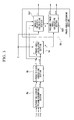
- FIG. 1 is a block diagram showing the functional configuration of a motor-driving device and a DC brushless motor subject to be driven according to the present embodiment.
- a reference numeral 1 indicates an inverter circuit
- 2 indicates a direct current power source
- 3 indicates a direct current voltage-detecting section
- 4 indicates an alternating current voltage-detecting section
- 5 and 6 indicate ammeters
- 7 indicates a microcomputer
- a reference symbol X indicates a 3-phase DC brushless motor
- Y indicates a turbine
- Z indicates a compressor.
- the inverter circuit 1 and the direct current power source 2 constitute a drive-signal-generating unit according to the present embodiment; and the direct-current voltage-detecting section 3, the alternating-voltage-detecting section 4, the ammeters 5 and 6, and the microcomputer 7 constitute a control-signal-generator unit according to the present invention.
- the 3-phase DC brushless motor X that is driven by the motor-driving device includes stator coils including a U phase coil Mu, a V phase coil Mv, and a W phase coil Mw that correspond to three phases including a U-phase, a V phase, and a W phase; and a rotor made of a magnetic-field-permanent magnet.
- the turbine Y has a rotation shaft that is common and coaxial with a rotation shaft of the 3-phase DC brushless motor X. Externally supplied gas drives and rotates the turbine Y, thereby actuating the compressor Z.
- the motor-driving device stops electric power delivery to the 3-phase DC brushless motor X rotated with the driving force supplied by the turbine Y in a relatively low rotation range.
- the motor-driving device in turn starting supplying electric power to the 3-phase DC brushless motor X accelerates the rotational velocity to several hundred thousand rpm.
- the motor-driving device drives a 3-phase DC brushless motor X based on the PWM sinusoidal wave modulation method.
- the inverter circuit 1 including three pairs of serially-connected switching circuits that correspond to 3-phase alternating electric current, switches direct current power based on PWM (Pulse Width Modulation) signals Au1, Au2, Av1, Av2, Aw1, and Aw2 that respectively correspond to three phases, i.e., a U-phase, a V phase, and a W phase as illustrated in the drawing and generates 3-phase driving signals Bu, Bv, and Bw.
- the driving signals Bu, Bv, and Bw are output from output terminals corresponding to each phase, i.e., a U phase output terminal, a V phase output terminal, and a W phase output terminal.
- Each output terminal of the inverter circuit 1 is connected to each stator coil, i.e., a U phase coil Mu, a V phase coil Mv, and a W phase coil Mw of the 3-phase DC brushless motor X.
- the direct current power source 2 supplies direct current power to the inverter circuit 1 having such a configuration.
- a semiconductor-switching element e.g., an Insulated Gate Bipolar Transistor (IGBT), and a free-wheeling diode of reversed polarity connected in parallel to the semiconductor-switching element constitute the above-explained switching circuit.
- IGBT Insulated Gate Bipolar Transistor
- the direct-current voltage-detecting section 3 is a resistive voltage divider composed by a pair of serial-connected resistors inserted between a reference point n and an input terminal of the inverter circuit 1. Dividing direct current voltage relative to the reference point n input into the inverter circuit 1 by each resistor provides a detected direct current voltage Vdn to be output to the microcomputer 5.
- the alternating-voltage-detecting section 4 is a resistive voltage divider composed by three pairs of serial-connected resistors inserted between the reference point n and output terminals (a U phase output terminal, a V phase output terminal, and a W phase output terminal) of the inverter circuit 1.
- Dividing voltage relative to the reference point n output from each output terminal of the inverter circuit 1 by each resistor provides detected alternating voltages Vun, Vvn, and Vwn to be output to the microcomputer 7.
- the ammeter 5 detects electric current (U phase current iu) flowing in the U phase coil Mu to output it to the microcomputer 7, and the ammeter 6 detects electric current (W phase current iw) flowing in the W phase coil Mw to output it to the microcomputer 7.
- the microcomputer 7 intermittently generates the pulse-control PWM signals Au1, Au2, Av1, Av2, Aw1, and Aw2 corresponding to the PWM sinusoidal wave modulation method based on an externally-input velocity command ⁇ ', the above-explained detected direct current voltage Vdn, and the detected alternating voltage Vun, Vvn, and Vwn to supply the generated signals to the inverter circuit 1.
- the inverter circuit 1 is controlled by the PWM signals Au1, Au2, Av1, Av2, Aw1, and Aw2 that are sequentially and continuously generated based on a cycle synchronous to the revolution of the 3-phase DC brushless motor X.
- the process for generating the PWM signals Au1, Au2, Av1, Av2, Aw1, and Aw2 is suspended every one or two rotations during a predetermined period, i.e., an intermission period T based on the operation state of the 3-phase DC brushless motor X.
- the microcomputer 7 generates the PWM signals Au1, Au2, Av1, Av2, Aw1, and Aw2 by detecting the operation state of the 3-phase DC brushless motor X based on the detected alternating voltages Vun, Vvn, and Vwn obtained during the intermission period T during which the generation of the PWM signals Au1, Au2, Av1, Av2, Aw1, and Aw2 is suspended.
- the method for setting the above-explained intermission period T will be explained later.
- the detected alternating voltages Vun, Vvn, and Vwn output from the alternating-detecting section 4 during the intermission period T are based not on the driving signals Bu, Bv, and Bw but on the induced voltage Cu, Cv, and Cw.
- FIG. 2 is a control block diagram explaining the control function of the microcomputer 7.
- the control function is brought into practice by a control program written in the microcomputer 7.
- the control function of the microcomputer 7 consists of: a phase-detecting section 8; a PWM (Pulse Width Modulation) intermission period-generating section 9; subtractor sections 10 and 13; PI gain-setting sections 11 and 15; limiters 12 and 16; an induced-current-calculating section 14; an adder section 17; a divider section 18; and a PWM (Pulse Width Modulation) signal-generating section 19.
- the microcomputer 7 controls the inverter circuit 1 based on the control function having such structure.
- the phase-detecting section 8 calculates an angular velocity ⁇ TS , a presumed phase angle value ⁇ TS, and an inductor voltage Vm of the rotor of the 3-phase DC brushless motor X based on the detected alternating voltage Vun, Vvn, and Vwn supplied by the alternating-detecting section 4.
- its functionality consists of a alternating-voltage-converting section 8a, a 3-phase/2-phase converting section 8b, a phase angle-calculating section 8c, and a phase angle-presuming section 8d.
- the functionality of the phase angle-presuming section 8d consists of an angular velocity-calculating section 8d1 and an estimated phase angle-divider section 8d2.
- the alternating-voltage-converting section 8a calculates a U phase voltage Vu and a W phase voltage Vw by substituting the above-explained detected alternating voltages Vun, Vvn, and Vwn in equations (1) to (4) to supply them to the 3-phase/2-phase converting section 8b.
- Vuv Vun - Vvn
- the 3-phase/2-phase converting section 8b calculates an ⁇ -axis voltage V ⁇ and a ⁇ -axis voltage V ⁇ on a static rectangular coordinate system (a rectangular coordinate system having an ⁇ axis and a ⁇ axis) fixed on the rotor by substituting the above-explained U phase voltage Vu and the W phase voltage Vw in the following equation (5); thus, the obtained voltages are supplied to the phase angle-calculating section 8c and the angular velocity-calculating section 8d1.
- the intermission signal D indicating the above-explained intermission period T is supplied from a PWM intermission period-generating section 9 to the phase angle-calculating section 8c that calculates an instantaneous phase angle ⁇ n in the intermission period T based on the intermission signal D, the ⁇ -axis voltage V ⁇ , and the ⁇ -axis voltage V ⁇ . That is, the phase angle-calculating section 8c calculates the instantaneous phase angle ⁇ n and supplies it to the estimated phase angle-divider section 8d2 by substituting the ⁇ -axis voltage V ⁇ and the ⁇ -axis voltage V ⁇ in the following equation (6) only during the intermission period T.
- the instantaneous phase angle ⁇ n indicates the accurate rotational position of the rotor based on the induced voltages Cu, Cv, and Cw since the detected alternating voltages Vun, Vvn, and Vwn in the intermission period T are obtained by dividing the induced voltages Cu, Cv, and Cw. It should be noted that the instantaneous phase angle ⁇ n reasonably indicates an instantaneous value of a rotational angle of the rotor on the above-explained static rectangular coordinate system since the instantaneous phase angle ⁇ n is calculated based on the ⁇ -axis voltage V ⁇ and the ⁇ -axis voltage V ⁇ .
- ⁇ n tan - 1 v ⁇ / v ⁇
- the above-explained intermission signal D is also supplied from the PWM intermission period-generating section 9 to the angular velocity-calculating section 8d1 that substitutes the above-explained ⁇ -axis voltage V ⁇ and the ⁇ -axis voltage V ⁇ in the following equation (7), calculates an inductor voltage Vm in the intermission period T, and thereby outputs the calculated voltage to the adder section 17.
- the angular velocity-calculating section 8dl substitutes the inductor voltage Vm in the intermission period T in the following equation (8), calculates an angular velocity ⁇ n of the rotor in the intermission period T, and thereby supplies the calculated velocity to the estimated phase angle-divider section 8d2 and the adder section 10.
- a constant Ke in the equation (8) indicates an inductor voltage constant.
- V m v ⁇ 2 + v ⁇ 2
- the estimated phase angle-divider section 8d2 calculates an estimated value (an estimated instantaneous phase angle ⁇ TS ) of an instantaneous phase angle in a period from an intermission period T to a next intermission period T and supplies the calculated value to the PWM signal-generating section 19 by substituting an instantaneous phase angle ⁇ of the rotor in the intermission period T supplied from the phase angle-calculating section 8c and an angular velocity ⁇ n of the rotor in the intermission period T supplied from the angular velocity-calculating section 8d1 in the following equations (9) to (12).
- the estimated phase angle-divider section 8d2 calculates the latest value of acceleration a of the rotor by substituting an angular velocity ⁇ n obtained from a currently latest intermission period T and another angular velocity ⁇ n-1 obtained from the previous intermission period T in the following equation (9).
- the constant Tpwm in the equation (9) indicates a cycle (PWM intermission cycle) at which the intermission period T is generated.
- the PWM intermission cycle Tpwm is variably set by the PWM intermission period-generating section 7.
- ⁇ ( ⁇ n - ⁇ n - 1 ) / T pwm
- ⁇ n indicates a currently latest PWM intermission period
- ⁇ n-1 indicates a previous PWM intermission period
- the estimated phase angle-divider section 8d2 using the equation (10) integrates the acceleration an obtained based on the equation (9) and determines a estimated instantaneous angular velocity (compensated estimated instantaneous angular velocity ⁇ TS ) where an initial value is an angular velocity ⁇ n per every sampling cycle Ts of the detected alternating voltage Vun, Vvn, and Vwn in the microcomputer 7.
- the estimated phase angle-divider section 8d2 using the equation (11) further substitutes the obtained compensated estimated instantaneous angular velocity ⁇ TS in the equation (11) and integrates the substituted velocity to calculate the estimated instantaneous phase angle ⁇ TS .
- An initial value of the integration is an instantaneous phase angle ⁇ TS .
- the PWM intermission period-generating section 7 sets the above-explained intermission period T based on the angular velocity ⁇ TS supplied from the phase-detecting section 8 with respect to the phase-detecting section 8, and generates the above-explained intermission signal D for instructing the intermission period T that is supplied to the phase-detecting section 6, the induced-current-calculating section 14, and the PWM signal-generating section 19. That is, the PWM intermission period-generating section 7 outputting the intermission signal D indicating the timing of such intermission period T determines whether or not the 3-phase DC brushless motor X is in an accelerated state based on the change in the angular velocity ⁇ supplied from the phase-detecting section 6 every intermission period T.
- the PWM intermission period-generating section 7 sets the intermission period T every one revolution of the rotor in the accelerated state, and sets one intermission period T every two revolutions of the rotor in a constant velocity state.
- the generation cycle i.e., the above-explained PWM intermission cycle Tpwm varies based on the rotational velocity of the rotor.
- the duration of the intermission period T is set at a predetermined angular region, e.g., a time corresponding to 30 degrees with respect to one revolution (360 degrees) of the rotor; thus, the duration varies based on the rotational velocity of the rotor.
- the PWM intermission period-generating section 7 eliminates the reflux period of each free-wheeling diode constituting the inverter circuit 1 when the timing of the intermission period T is set; thus, influence of the reflux current during the reflux period is eliminated.
- the subtractor section 10 calculates a velocity error ⁇ of the angular velocity ⁇ of the rotor with respect to the velocity command ⁇ ' by subtracting the angular velocity ⁇ TS of the rotor supplied from the angular velocity-calculating section 8d2 (estimated phase angle-divider section 8d2) from the externally supplied velocity command ⁇ ', thus the calculated velocity is supplied to a PI gain-setting section 11.
- the PI gain-setting section 11 generates and supplies electric current I to a limiter 12 by conducting a proportional-integral process by means of a predetermined PI gain with respect to the above-explained velocity error ⁇ .
- the limiter 12 supplies electric current I' to the subtractor section 13 by limiting the above-explained electric current I within a predetermined limited value.
- the subtractor section 13 generates and supplies error current ⁇ I to the PI gain-setting section 15 by subtracting induced electric current Im supplied from the induced-current-calculating section 14 from the above-explained electric current I'.
- the induced-current-calculating section 14 calculates ⁇ axis electric current I ⁇ and ⁇ axis electric current I ⁇ on the static rectangular coordinate system, i.e., a rectangular coordinate system having an ⁇ axis and a ⁇ axis fixed on the stator by substituting the U phase current iu supplied from the ammeter 5 and the W phase current iw supplied from the ammeter 6 in the following equation (12).
- the induced-current-calculating section 14 further calculates and supplies an induction electric current Im to the above-explained subtractor section 13 by substituting the ⁇ axis electric current I ⁇ and the ⁇ axis electric current I ⁇ in the following equation (13).
- I m i ⁇ 2 + i ⁇ 2
- the PI gain-setting section 15 generates and supplies voltage V to a limiter 16 by conducting proportional-integral process by means of a predetermined PI gain with respect to the above-explained error electric current ⁇ I.
- the limiter 16 supplies voltage V' to an adder section 17 by limiting the voltage V within a predetermined limited value.
- the adder section 17 generates and supplies voltage Vs to a divider section 18 by adding inductor voltage Vm supplied from the angle-calculating section 8d1 to the voltage V'.
- the divider section 18 generates and supplies a velocity control value S to the PWM signal-generating section 19 by subtracting the detected direct current voltage Vdn supplied from the direct-current voltage-detecting section 3 from the voltage Vs.
- the PWM signal-generating section 19 generates and supplies the PWM signals Au1, Au2, Av1, Av2, Aw1, and Aw2 to the inverter circuit 1 based on the above-explained velocity control value S and the estimated instantaneous phase angle ⁇ TS as an angle control value supplied from the estimated phase angle-divider section 8d2.
- the PWM signal-generating section 19 Based on the intermission signal D supplied from the PWM intermission period-generating section 9 to the PWM signal-generating section 19, the PWM signal-generating section 19 conducts a process for generating the PWM signals Au1, Au2, Av1, Av2, Aw1, and Aw2 except in the intermission period T, and suspends the process for generating the PWM signals Au1, Au2, Av1, Av2, Aw1, and Aw2 during the intermission period T.
- FIG. 4 is a timing diagram explaining the relationship between the intermission period T in the accelerated state of the 3-phase DC brushless motor X and the timing for generating the PWM signals Au1, Au2, Av1, Av2, Aw1, and Aw2.
- the PWM intermission period-generating section 7 sets the intermission period T at every one revolution of the rotor if it is determined that the 3-phase DC brushless motor X is in the accelerated state based on the angular velocity ⁇ TS supplied from the phase-detecting section 6 at every intermission period T.
- the fluctuating cycle of the inductor voltage Vm is the same as the revolution cycle of the rotor since the sinusoidal inductor voltage Vm varies synchronously with the revolution of the rotor.
- the PWM intermission period-generating section 7 sets the intermission period T having a predetermined duration, by every one revolution of the rotor, i.e., every fluctuating cycle of the inductor voltage Vm when the 3-phase DC brushless motor X is in the accelerated state, and the PWM signal-generating section 19 accordingly suspends the generation of the PWM signals Au1, Au2, Av1, Av2, Aw1, and Aw2 during the intermission period T.
- the inductor voltage Vm, the angular velocity ⁇ , and the estimated instantaneous phase angle ⁇ TS indicate the rotational state of the rotor accurately since the phase-detecting section 8 calculates the inductor voltage Vm, the angular velocity ⁇ , and the estimated instantaneous phase angle ⁇ TS in the intermission period T based on the detected alternating voltage Vun, Vvn, and Vwn, and since noise caused by generated PWM signals Au1, Au2, Av1, Av2, Aw1, and Aw2 does not act as disturbance,
- the velocity control value S calculated based on such inductor voltage Vm and angular velocity ⁇ accurately represent the rotational state of the rotor; and also the estimated instantaneous phase angle ⁇ TS is the angle control value accurately representing the rotational state of the rotor; and the PWM signals Au1, Au2, Av1, Av2, Aw1, and Aw2 generated except in the intermission period T based on the angle control value and the velocity control value S appropriately controls the inverter circuit 1 and reliably and accurately drives the 3-phase DC brushless motor X.
- the motor-driving device therefore allows accurate and reliable detection of the rotational position of the rotor, thereby driving the 3-phase DC brushless motor X accurately and reliably.
- the present invention is not limited to the above embodiment; for example, the following modification may be available.
Landscapes
- Engineering & Computer Science (AREA)
- Power Engineering (AREA)
- Control Of Motors That Do Not Use Commutators (AREA)
Abstract
Description
- The present invention relates to a motor-driving apparatus.
- A hundred-and-twenty-degree modulation method and PWM (Pulse Width Modulation) sinusoidal wave modulation method are conventionally known as methods for driving DC brushless motors. Inductor voltage obtained during non-pulse intervals (periods) is used for detecting the rotational position of a DC brushless motor based on the 120-degree modulation method of some type without using position sensors, e.g., rotary encoders, resolvers, and hall elements.
- For example,
Japanese Unexamined Patent Application, First Publication No. H9-266690 - In addition,
Japanese Unexamined Patent Application, First Publication No. 2000-218787
Patent document 1: Japanese Unexamined Patent Application, First Publication No. H9-266690
Patent Document 2:Japanese Unexamined Patent Application, First Publication No. 2002-218787 - The aforementioned conventional technology that detects rotational positions by means of inductor voltage during non-pulse intervals is effective in a rotation range, e.g., several thousand rpm. However, the technology is not effective in a high revolution range, e.g. over several tens of thousand rpm because noise overlapping inductor voltage, and fewer input signal samples destabilize a control circuit, i.e., a digital circuit like a microcomputer. Specifically, the rotational positions of the rotor of a driven DC brushless motor must be accurately detected since higher revolution shortens rotation cycles. However, the inductor voltage cannot be obtained accurately and reliably since higher revolution shortens the non-pulse intervals; and pulse-control signal input into a driving circuit results in noise components, e.g., high frequency components that overlap the inductor voltage obtained during the shortened non-pulse intervals.
- In addition, an idea of eliminating the noise by means of filters, e.g., low-pass filters to obtain the inductor voltage is problematic since the phase of the inductor voltage having changed from an original phase due to the usage of the filters provides an error in detecting the rotational positions of the rotor, thereby disturbing accurate detection of the rotational positions. In addition, the error causes an extremely serious problem in significantly changing the revolution of a DC brushless motor driven in the high revolution range over several tens of thousand rpm. Furthermore, another problem is that a design of the wide revolution range filter will be difficult.
Incidentally, extending the non-pulse intervals to control the phase of the driving current as disclosed byJapanese Unexamined Patent Application, First Publication No. 2002-218787 - The present invention was conceived in considering the aforementioned circumstances, and it is an object of the present invention to accurately and reliably detect rotational positions of a rotor irrespective of noise overlapping inductor voltage.
- Employed for accomplishing the aforementioned object in the present invention is a motor-driving device for rotating and driving a rotor by supplying predetermined drive signals to stator coils each corresponding to each phase of a DC brushless motor, the device including: a drive-signal-generating unit for generating the drive signals by switching direct current power based on a pulse-control signal; and a control-signal-generator unit for generating the pulse-control signal that controls the drive-signal-generating unit by intermittently generating the pulse-control signal and for detecting the rotational position and the rotational velocity of the rotor based on inductor voltage obtained from the stator coils in a period in which generation of the pulse-control signal is suspended in each phase.
- The present invention enables a rotational state of a rotor to be accurately and reliably detected since the rotational state of the rotor is detected based on inductor voltage obtained from stator coils during a period wherein generation of a pulse-control signal is suspended; and the pulse-control signal is generated based on the rotational state. Therefore, generating the pulse-control signal based on the thus accurately detected rotational state permits reliably and accurately driving the DC brushless motor.
-
- FIG. 1 is a block diagram showing the functional configuration of a motor-driving device and a DC brushless motor subject to be driven according to an embodiment of the present invention.
- FIG. 2 is a control block diagram describing control operation conducted by a
microcomputer 5 according to an embodiment of the present invention. - FIG 3 is a control block diagram describing in detail a phase-detecting section illustrated in FIG. 2.
- FIG. 4 is a timing diagram illustrating operation timing of the motor-driving device according to an embodiment of the present invention.
-
- 1
- inverter circuit
- 2
- direct current power source
- 3
- direct current voltage-detecting section
- 4
- alternating current voltage-detecting section
- 5 and 6
- ammeters
- 7
- microcomputer
- X
- 3-phase DC brushless motor
- Y
- turbine
- Z
- compressor
- An embodiment of the present invention will be explained below with reference to the drawings.
FIG. 1 is a block diagram showing the functional configuration of a motor-driving device and a DC brushless motor subject to be driven according to the present embodiment. In this drawing, areference numeral 1 indicates an inverter circuit, 2 indicates a direct current power source, 3 indicates a direct current voltage-detecting section, 4 indicates an alternating current voltage-detecting section, 5 and 6 indicate ammeters, 7 indicates a microcomputer, a reference symbol X indicates a 3-phase DC brushless motor, Y indicates a turbine, and Z indicates a compressor. - Among these components, the
inverter circuit 1 and the directcurrent power source 2 constitute a drive-signal-generating unit according to the present embodiment; and the direct-current voltage-detectingsection 3, the alternating-voltage-detectingsection 4, theammeters - The 3-phase DC brushless motor X that is driven by the motor-driving device includes stator coils including a U phase coil Mu, a V phase coil Mv, and a W phase coil Mw that correspond to three phases including a U-phase, a V phase, and a W phase; and a rotor made of a magnetic-field-permanent magnet. The turbine Y has a rotation shaft that is common and coaxial with a rotation shaft of the 3-phase DC brushless motor X. Externally supplied gas drives and rotates the turbine Y, thereby actuating the compressor Z.
- To be more specific, the motor-driving device stops electric power delivery to the 3-phase DC brushless motor X rotated with the driving force supplied by the turbine Y in a relatively low rotation range. When the revolution reaches a high revolution range over several tens of thousand rpm, the motor-driving device in turn starting supplying electric power to the 3-phase DC brushless motor X accelerates the rotational velocity to several hundred thousand rpm. Note that the motor-driving device drives a 3-phase DC brushless motor X based on the PWM sinusoidal wave modulation method.
- The
inverter circuit 1, including three pairs of serially-connected switching circuits that correspond to 3-phase alternating electric current, switches direct current power based on PWM (Pulse Width Modulation) signals Au1, Au2, Av1, Av2, Aw1, and Aw2 that respectively correspond to three phases, i.e., a U-phase, a V phase, and a W phase as illustrated in the drawing and generates 3-phase driving signals Bu, Bv, and Bw. The driving signals Bu, Bv, and Bw are output from output terminals corresponding to each phase, i.e., a U phase output terminal, a V phase output terminal, and a W phase output terminal. - Each output terminal of the
inverter circuit 1 is connected to each stator coil, i.e., a U phase coil Mu, a V phase coil Mv, and a W phase coil Mw of the 3-phase DC brushless motor X. The directcurrent power source 2 supplies direct current power to theinverter circuit 1 having such a configuration. A semiconductor-switching element, e.g., an Insulated Gate Bipolar Transistor (IGBT), and a free-wheeling diode of reversed polarity connected in parallel to the semiconductor-switching element constitute the above-explained switching circuit. - The direct-current voltage-detecting
section 3 is a resistive voltage divider composed by a pair of serial-connected resistors inserted between a reference point n and an input terminal of theinverter circuit 1. Dividing direct current voltage relative to the reference point n input into theinverter circuit 1 by each resistor provides a detected direct current voltage Vdn to be output to themicrocomputer 5. The alternating-voltage-detectingsection 4 is a resistive voltage divider composed by three pairs of serial-connected resistors inserted between the reference point n and output terminals (a U phase output terminal, a V phase output terminal, and a W phase output terminal) of theinverter circuit 1. Dividing voltage relative to the reference point n output from each output terminal of theinverter circuit 1 by each resistor provides detected alternating voltages Vun, Vvn, and Vwn to be output to the microcomputer 7. In addition, theammeter 5 detects electric current (U phase current iu) flowing in the U phase coil Mu to output it to the microcomputer 7, and theammeter 6 detects electric current (W phase current iw) flowing in the W phase coil Mw to output it to the microcomputer 7. - The microcomputer 7 intermittently generates the pulse-control PWM signals Au1, Au2, Av1, Av2, Aw1, and Aw2 corresponding to the PWM sinusoidal wave modulation method based on an externally-input velocity command ω', the above-explained detected direct current voltage Vdn, and the detected alternating voltage Vun, Vvn, and Vwn to supply the generated signals to the
inverter circuit 1. - That is, the
inverter circuit 1 is controlled by the PWM signals Au1, Au2, Av1, Av2, Aw1, and Aw2 that are sequentially and continuously generated based on a cycle synchronous to the revolution of the 3-phase DC brushless motor X. On the other hand, the process for generating the PWM signals Au1, Au2, Av1, Av2, Aw1, and Aw2 is suspended every one or two rotations during a predetermined period, i.e., an intermission period T based on the operation state of the 3-phase DC brushless motor X. Also, the microcomputer 7 generates the PWM signals Au1, Au2, Av1, Av2, Aw1, and Aw2 by detecting the operation state of the 3-phase DC brushless motor X based on the detected alternating voltages Vun, Vvn, and Vwn obtained during the intermission period T during which the generation of the PWM signals Au1, Au2, Av1, Av2, Aw1, and Aw2 is suspended. The method for setting the above-explained intermission period T will be explained later. - Since the PWM signals Au1, Au2, Av1, Av2, Aw1, and Aw2 are not supplied to the
inverter circuit 1 during the above-explained intermission period T, driving signals Bu, Bv, and Bw are not output to each output terminal of theinverter circuit 1, i.e., the 3-phase DC brushless motor X is in a non-pulsed state. Therefore, voltage induced at each output terminal of theinverter circuit 1 become induced voltage Cu, Cv, and Cw induced by the rotor of the 3-phase DC brushless motor X at the stator coils, i.e., the U phase coil Mu, the V phase coil Mv, and the W phase coil Mw. - Specifically, the detected alternating voltages Vun, Vvn, and Vwn output from the alternating-detecting
section 4 during the intermission period T are based not on the driving signals Bu, Bv, and Bw but on the induced voltage Cu, Cv, and Cw. - Explained next with reference to FIGS. 2 to 4 is a comprehensive operation of the motor-driving device having such a configuration.
- FIG. 2 is a control block diagram explaining the control function of the microcomputer 7. The control function is brought into practice by a control program written in the microcomputer 7. As illustrated in the drawing, the control function of the microcomputer 7 consists of: a phase-detecting
section 8; a PWM (Pulse Width Modulation) intermission period-generating section 9;subtractor sections sections limiters section 14; anadder section 17; adivider section 18; and a PWM (Pulse Width Modulation) signal-generatingsection 19. The microcomputer 7 controls theinverter circuit 1 based on the control function having such structure. - The phase-detecting
section 8 calculates an angular velocity ωTS, a presumed phase angle value θTS, and an inductor voltage Vm of the rotor of the 3-phase DC brushless motor X based on the detected alternating voltage Vun, Vvn, and Vwn supplied by the alternating-detectingsection 4. As illustrated in FIG. 3, its functionality consists of a alternating-voltage-convertingsection 8a, a 3-phase/2-phase converting section 8b, a phase angle-calculatingsection 8c, and a phase angle-presumingsection 8d. The functionality of the phase angle-presumingsection 8d consists of an angular velocity-calculating section 8d1 and an estimated phase angle-divider section 8d2. - The alternating-voltage-converting
section 8a calculates a U phase voltage Vu and a W phase voltage Vw by substituting the above-explained detected alternating voltages Vun, Vvn, and Vwn in equations (1) to (4) to supply them to the 3-phase/2-phase converting section 8b.


- The 3-phase/2-
phase converting section 8b calculates an α-axis voltage Vα and a β-axis voltage Vβ on a static rectangular coordinate system (a rectangular coordinate system having an α axis and a β axis) fixed on the rotor by substituting the above-explained U phase voltage Vu and the W phase voltage Vw in the following equation (5); thus, the obtained voltages are supplied to the phase angle-calculatingsection 8c and the angular velocity-calculating section 8d1. -

- The intermission signal D indicating the above-explained intermission period T is supplied from a PWM intermission period-generating section 9 to the phase angle-calculating
section 8c that calculates an instantaneous phase angle θn in the intermission period T based on the intermission signal D, the α-axis voltage Vα, and the β-axis voltage Vβ. That is, the phase angle-calculatingsection 8c calculates the instantaneous phase angle θn and supplies it to the estimated phase angle-divider section 8d2 by substituting the α-axis voltage Vα and the β-axis voltage Vβ in the following equation (6) only during the intermission period T. - The instantaneous phase angle θn indicates the accurate rotational position of the rotor based on the induced voltages Cu, Cv, and Cw since the detected alternating voltages Vun, Vvn, and Vwn in the intermission period T are obtained by dividing the induced voltages Cu, Cv, and Cw. It should be noted that the instantaneous phase angle θn reasonably indicates an instantaneous value of a rotational angle of the rotor on the above-explained static rectangular coordinate system since the instantaneous phase angle θn is calculated based on the α-axis voltage Vα and the β-axis voltage Vβ.
-

- The above-explained intermission signal D is also supplied from the PWM intermission period-generating section 9 to the angular velocity-calculating section 8d1 that substitutes the above-explained α-axis voltage Vα and the β-axis voltage Vβ in the following equation (7), calculates an inductor voltage Vm in the intermission period T, and thereby outputs the calculated voltage to the
adder section 17. Simultaneously, the angular velocity-calculating section 8dl substitutes the inductor voltage Vm in the intermission period T in the following equation (8), calculates an angular velocity ωn of the rotor in the intermission period T, and thereby supplies the calculated velocity to the estimated phase angle-divider section 8d2 and theadder section 10. A constant Ke in the equation (8) indicates an inductor voltage constant. -

-

- The estimated phase angle-divider section 8d2 calculates an estimated value (an estimated instantaneous phase angle θTS) of an instantaneous phase angle in a period from an intermission period T to a next intermission period T and supplies the calculated value to the PWM signal-generating
section 19 by substituting an instantaneous phase angle θ of the rotor in the intermission period T supplied from the phase angle-calculatingsection 8c and an angular velocity ωn of the rotor in the intermission period T supplied from the angular velocity-calculating section 8d1 in the following equations (9) to (12). - To be more specific, the estimated phase angle-divider section 8d2 calculates the latest value of acceleration a of the rotor by substituting an angular velocity ωn obtained from a currently latest intermission period T and another angular velocity ωn-1 obtained from the previous intermission period T in the following equation (9). The constant Tpwm in the equation (9) indicates a cycle (PWM intermission cycle) at which the intermission period T is generated. The PWM intermission cycle Tpwm is variably set by the PWM intermission period-generating section 7.
-

where ωn indicates a currently latest PWM intermission period, and
ωn-1 indicates a previous PWM intermission period - Furthermore, the estimated phase angle-divider section 8d2 using the equation (10) integrates the acceleration an obtained based on the equation (9) and determines a estimated instantaneous angular velocity (compensated estimated instantaneous angular velocity ωTS) where an initial value is an angular velocity ωn per every sampling cycle Ts of the detected alternating voltage Vun, Vvn, and Vwn in the microcomputer 7. The estimated phase angle-divider section 8d2 using the equation (11) further substitutes the obtained compensated estimated instantaneous angular velocity ωTS in the equation (11) and integrates the substituted velocity to calculate the estimated instantaneous phase angle θTS. An initial value of the integration is an instantaneous phase angle θTS.
-

where an initial value of the integration is ωn -

where an initial value of the integration is θn - The PWM intermission period-generating section 7 sets the above-explained intermission period T based on the angular velocity ωTS supplied from the phase-detecting
section 8 with respect to the phase-detectingsection 8, and generates the above-explained intermission signal D for instructing the intermission period T that is supplied to the phase-detectingsection 6, the induced-current-calculatingsection 14, and the PWM signal-generatingsection 19. That is, the PWM intermission period-generating section 7 outputting the intermission signal D indicating the timing of such intermission period T determines whether or not the 3-phase DC brushless motor X is in an accelerated state based on the change in the angular velocity ω supplied from the phase-detectingsection 6 every intermission period T. The PWM intermission period-generating section 7 sets the intermission period T every one revolution of the rotor in the accelerated state, and sets one intermission period T every two revolutions of the rotor in a constant velocity state. - Since the intermission period T is set at every one or two rotations of the rotor based on whether or not the 3-phase DC brushless motor X is in the accelerated state, the generation cycle, i.e., the above-explained PWM intermission cycle Tpwm varies based on the rotational velocity of the rotor. In addition, the duration of the intermission period T is set at a predetermined angular region, e.g., a time corresponding to 30 degrees with respect to one revolution (360 degrees) of the rotor; thus, the duration varies based on the rotational velocity of the rotor.
- Incidentally, the PWM intermission period-generating section 7 eliminates the reflux period of each free-wheeling diode constituting the
inverter circuit 1 when the timing of the intermission period T is set; thus, influence of the reflux current during the reflux period is eliminated. - The
subtractor section 10 calculates a velocity error Δω of the angular velocity ω of the rotor with respect to the velocity command ω' by subtracting the angular velocity ωTS of the rotor supplied from the angular velocity-calculating section 8d2 (estimated phase angle-divider section 8d2) from the externally supplied velocity command ω', thus the calculated velocity is supplied to a PI gain-settingsection 11. The PI gain-settingsection 11 generates and supplies electric current I to alimiter 12 by conducting a proportional-integral process by means of a predetermined PI gain with respect to the above-explained velocity error Δω. Thelimiter 12 supplies electric current I' to thesubtractor section 13 by limiting the above-explained electric current I within a predetermined limited value. Thesubtractor section 13 generates and supplies error current ΔI to the PI gain-settingsection 15 by subtracting induced electric current Im supplied from the induced-current-calculatingsection 14 from the above-explained electric current I'. - The induced-current-calculating
section 14 calculates α axis electric current Iα and β axis electric current Iβ on the static rectangular coordinate system, i.e., a rectangular coordinate system having an α axis and a β axis fixed on the stator by substituting the U phase current iu supplied from theammeter 5 and the W phase current iw supplied from theammeter 6 in the following equation (12). The induced-current-calculatingsection 14 further calculates and supplies an induction electric current Im to the above-explainedsubtractor section 13 by substituting the α axis electric current Iα and the β axis electric current Iβ in the following equation (13). -

-

- The PI gain-setting
section 15 generates and supplies voltage V to alimiter 16 by conducting proportional-integral process by means of a predetermined PI gain with respect to the above-explained error electric current ΔI. Thelimiter 16 supplies voltage V' to anadder section 17 by limiting the voltage V within a predetermined limited value. Theadder section 17 generates and supplies voltage Vs to adivider section 18 by adding inductor voltage Vm supplied from the angle-calculating section 8d1 to the voltage V'. Thedivider section 18 generates and supplies a velocity control value S to the PWM signal-generatingsection 19 by subtracting the detected direct current voltage Vdn supplied from the direct-current voltage-detectingsection 3 from the voltage Vs. - The PWM signal-generating
section 19 generates and supplies the PWM signals Au1, Au2, Av1, Av2, Aw1, and Aw2 to theinverter circuit 1 based on the above-explained velocity control value S and the estimated instantaneous phase angle θTS as an angle control value supplied from the estimated phase angle-divider section 8d2. Based on the intermission signal D supplied from the PWM intermission period-generating section 9 to the PWM signal-generatingsection 19, the PWM signal-generatingsection 19 conducts a process for generating the PWM signals Au1, Au2, Av1, Av2, Aw1, and Aw2 except in the intermission period T, and suspends the process for generating the PWM signals Au1, Au2, Av1, Av2, Aw1, and Aw2 during the intermission period T. - FIG. 4 is a timing diagram explaining the relationship between the intermission period T in the accelerated state of the 3-phase DC brushless motor X and the timing for generating the PWM signals Au1, Au2, Av1, Av2, Aw1, and Aw2. The PWM intermission period-generating section 7 sets the intermission period T at every one revolution of the rotor if it is determined that the 3-phase DC brushless motor X is in the accelerated state based on the angular velocity ωTS supplied from the phase-detecting
section 6 at every intermission period T. - The fluctuating cycle of the inductor voltage Vm is the same as the revolution cycle of the rotor since the sinusoidal inductor voltage Vm varies synchronously with the revolution of the rotor. The PWM intermission period-generating section 7 sets the intermission period T having a predetermined duration, by every one revolution of the rotor, i.e., every fluctuating cycle of the inductor voltage Vm when the 3-phase DC brushless motor X is in the accelerated state, and the PWM signal-generating
section 19 accordingly suspends the generation of the PWM signals Au1, Au2, Av1, Av2, Aw1, and Aw2 during the intermission period T. - In contrast, the inductor voltage Vm, the angular velocity ω, and the estimated instantaneous phase angle θTS indicate the rotational state of the rotor accurately since the phase-detecting
section 8 calculates the inductor voltage Vm, the angular velocity ω, and the estimated instantaneous phase angle θTS in the intermission period T based on the detected alternating voltage Vun, Vvn, and Vwn, and since noise caused by generated PWM signals Au1, Au2, Av1, Av2, Aw1, and Aw2 does not act as disturbance, - Therefore, the velocity control value S calculated based on such inductor voltage Vm and angular velocity ω accurately represent the rotational state of the rotor; and also the estimated instantaneous phase angle θTS is the angle control value accurately representing the rotational state of the rotor; and the PWM signals Au1, Au2, Av1, Av2, Aw1, and Aw2 generated except in the intermission period T based on the angle control value and the velocity control value S appropriately controls the
inverter circuit 1 and reliably and accurately drives the 3-phase DC brushless motor X. The motor-driving device therefore allows accurate and reliable detection of the rotational position of the rotor, thereby driving the 3-phase DC brushless motor X accurately and reliably. - In addition, the present invention is not limited to the above embodiment; for example, the following modification may be available.
- (1) The present invention is not limited to the above-explained embodiment in which the 3-phase DC brushless motor X in the motor-driving device is driven based on the PWM sinusoidal wave modulation method; thus the present invention may be applied to a case in which the 3-phase DC brushless motor X is driven based on the 120-degree modulation method.
-
- (2) The method for setting the intermission period T is not limited to the above-explained embodiment in which the PWM intermission period-generating section 7 sets the intermission period T every one rotation of the rotor if the 3-phase DC brushless motor X is in an accelerated state, and sets the intermission period T every two rotations of the rotor if the 3-phase DC brushless motor X is in a constant velocity state. The method for setting the intermission period T may be changed based on operation capability requirement with respect to the 3-phase DC brushless motor X.
-
- (3) The configuration with respect to the drive-signal-generating unit and the control-signal-generator unit may not be limited to the above-explained embodiment in which the
inverter circuit 1 and the directcurrent power source 2 constitute the drive-signal-generating unit, and also the direct-current voltage-detectingsection 3, the alternating-voltage-detectingsection 4, theammeters inverter circuit 1 conducted by the microcomputer 7 according to the above-explained embodiment. -
- (4) The advantage of the present invention is not limited to operation conducted in a high revolution range in which the 3-phase DC brushless motor X is actuated over several tens of thousand rpm.
Claims (16)
- A motor-driving device for rotating and driving a rotor by supplying predetermined drive signals to stator coils each corresponding to each phase of a DC brushless motor, the device comprising:a drive-signal-generating unit for generating the drive signals by switching direct current power based on a pulse-control signal; anda control-signal-generator unit for generating the pulse-control signal that controls the drive-signal-generating unit by intermittently generating the pulse-control signal; and for detecting the rotational position and the rotational velocity of the rotor based on inductor voltage obtained from the stator coils in a period in which generation of the pulse-control signal is suspended in each phase.
- The motor-driving device according to Claim 1, wherein the drive-signal-generating unit is composed of a direct current power source and an inverter circuit for generating a drive signal by switching the direct current power based on the pulse-control signal.
- The motor-driving device according to Claim 1, wherein the control-signal-generator unit generates pulse-control PWM (Pulse Width Modulation) signals.
- The motor-driving device according to Claim 2, wherein the control-signal-generator unit generates pulse-control PWM (Pulse Width Modulation) signals.
- The motor-driving device according to Claim 1, wherein when a free-wheeling diode is connected in parallel to a switching element of a drive-signal-generating unit, the control-signal-generator unit detects the rotational state of the rotor in a period in which the generation of the pulse-control signal is suspended based on signals obtained from the stator coils except in a reflux period of the free-wheeling diode.
- The motor-driving device according to Claim 2, wherein when a free-wheeling diode is connected in parallel to a switching element of a drive-signal-generating unit, the control-signal-generator unit detects the rotational state of the rotor in a period in which the generation of the pulse-control signal is suspended based on signals obtained from the stator coils except in a reflux period of the free-wheeling diode.
- The motor-driving device according to Claim 3, wherein when a free-wheeling diode is connected in parallel to a switching element of a drive-signal-generating unit, the control-signal-generator unit detects the rotational state of the rotor in a period in which the generation of the pulse-control signal is suspended based on signals obtained from the stator coils except in a reflux period of the free-wheeling diode.
- The motor-driving device according to Claim 4, wherein when a free-wheeling diode is connected in parallel to a switching element of a drive-signal-generating unit, the control-signal-generator unit detects the rotational state of the rotor in a period in which the generation of the pulse-control signal is suspended based on signals obtained from the stator coils except in a reflux period of the free-wheeling diode.
- The motor-driving device according to Claim 1, wherein the control-signal-generator unit generates a pulse-control signal corresponding to a PWM sinusoidal wave modulation method.
- The motor-driving device according to Claim 2, wherein the control-signal-generator unit generates a pulse-control signal corresponding to a PWM sinusoidal wave modulation method.
- The motor-driving device according to Claim 3, wherein the control-signal-generator unit generates a pulse-control signal corresponding to a PWM sinusoidal wave modulation method.
- The motor-driving device according to Claim 4, wherein the control-signal-generator unit generates a pulse-control signal corresponding to a PWM sinusoidal wave modulation method.
- The motor-driving device according to Claim 5, wherein the control-signal-generator unit generates a pulse-control signal corresponding to a PWM sinusoidal wave modulation method.
- The motor-driving device according to Claim 6, wherein the control-signal-generator unit generates a pulse-control signal corresponding to a PWM sinusoidal wave modulation method.
- The motor-driving device according to Claim 7, wherein the control-signal-generator unit generates a pulse-control signal corresponding to a PWM sinusoidal wave modulation method.
- The motor-driving device according to Claim 8, wherein the control-signal-generator unit generates a pulse-control signal corresponding to a PWM sinusoidal wave modulation method.
Applications Claiming Priority (2)
| Application Number | Priority Date | Filing Date | Title |
|---|---|---|---|
| JP2004305569A JP2006121798A (en) | 2004-10-20 | 2004-10-20 | Motor drive device |
| PCT/JP2005/019185 WO2006043584A1 (en) | 2004-10-20 | 2005-10-19 | Motor driving apparatus |
Publications (3)
| Publication Number | Publication Date |
|---|---|
| EP1806835A1 true EP1806835A1 (en) | 2007-07-11 |
| EP1806835A4 EP1806835A4 (en) | 2009-11-25 |
| EP1806835B1 EP1806835B1 (en) | 2012-01-04 |
Family
ID=36202998
Family Applications (1)
| Application Number | Title | Priority Date | Filing Date |
|---|---|---|---|
| EP05795099A Expired - Lifetime EP1806835B1 (en) | 2004-10-20 | 2005-10-19 | Motor driving apparatus |
Country Status (6)
| Country | Link |
|---|---|
| US (1) | US7567046B2 (en) |
| EP (1) | EP1806835B1 (en) |
| JP (1) | JP2006121798A (en) |
| KR (2) | KR20070073876A (en) |
| CN (1) | CN101080867B (en) |
| WO (1) | WO2006043584A1 (en) |
Families Citing this family (6)
| Publication number | Priority date | Publication date | Assignee | Title |
|---|---|---|---|---|
| CN102082538B (en) * | 2011-01-25 | 2013-01-16 | 浙江工业大学 | Method and device for adjusting speed of direct current motor |
| JP5364138B2 (en) * | 2011-09-29 | 2013-12-11 | 日立アプライアンス株式会社 | Motor drive control device and air conditioner |
| KR101234778B1 (en) * | 2011-10-05 | 2013-02-20 | 이상현 | Apparatus and method for reducing velocity of sensorless brush less direct current motor |
| JP5975830B2 (en) * | 2012-10-09 | 2016-08-23 | 日立アプライアンス株式会社 | Motor control device and refrigeration equipment using the same |
| JP2017103927A (en) * | 2015-12-02 | 2017-06-08 | トヨタ自動車株式会社 | Motor control device |
| US10256756B2 (en) * | 2016-09-27 | 2019-04-09 | Brother Kogyo Kabushiki Kaisha | Brushless motor apparatus setting mask period on the basis of comparison between voltage of specific coil and voltage of coil other than the specific coil |
Family Cites Families (33)
| Publication number | Priority date | Publication date | Assignee | Title |
|---|---|---|---|---|
| JPS62247791A (en) * | 1986-04-21 | 1987-10-28 | Matsushita Seiko Co Ltd | Commutatoress motor |
| US5017845A (en) * | 1990-10-05 | 1991-05-21 | Sgs-Thomson Microelectronics, Inc. | Brushless direct current motor starting and operating apparatus and method |
| JPH0965678A (en) * | 1995-08-25 | 1997-03-07 | Shinano Denki Kk | Sensorless brushless motor |
| CN1154598A (en) * | 1995-10-13 | 1997-07-16 | 株式会社杰克赛尔 | Method and device for driving DC brushless motor |
| JP3787729B2 (en) * | 1996-03-28 | 2006-06-21 | 三菱電機株式会社 | Sensorless brushless motor drive device |
| DE69607838T2 (en) * | 1996-08-01 | 2000-08-17 | Stmicroelectronics S.R.L., Agrate Brianza | Restore a back emf signal to synchronize the drive of a brushless and sensorless motor by redefining drive signals |
| JP3282537B2 (en) * | 1997-04-28 | 2002-05-13 | 松下電器産業株式会社 | Motor drive |
| JPH10340693A (en) | 1997-06-06 | 1998-12-22 | Futaba Corp | Color field emission type display apparatus and its manufacture |
| US5866998A (en) * | 1997-10-24 | 1999-02-02 | Stmicroelectronics, Inc. | Circuit for improving back emf detection in pulse width modulation mode |
| US6252362B1 (en) * | 1999-11-23 | 2001-06-26 | Texas Instruments Incorporated | Method and apparatus for synchronizing PWM sinusoidal drive to a DC motor |
| US6121736A (en) * | 1998-07-10 | 2000-09-19 | Matsushita Electric Industrial Co., Ltd. | Control apparatus for motor, and motor unit having the control apparatus |
| JP2000175483A (en) * | 1998-10-02 | 2000-06-23 | Kobe Steel Ltd | Sensorless control method for synchronous motor and its apparatus |
| JP2000134981A (en) * | 1998-10-29 | 2000-05-12 | Toshiba Corp | Motor drive |
| JP2000218787A (en) | 1999-01-29 | 2000-08-08 | Seiko Epson Corp | Ink jet recording head and image recording device |
| JP2001178176A (en) * | 1999-12-10 | 2001-06-29 | Tokimec Inc | Control apparatus for servo motor |
| JP2002010688A (en) * | 2000-06-22 | 2002-01-11 | Canon Inc | Motor drive control device |
| JP4465129B2 (en) * | 2000-07-14 | 2010-05-19 | パナソニック株式会社 | Brushless motor driving apparatus and driving method |
| WO2002008202A2 (en) * | 2000-07-21 | 2002-01-31 | Elan Pharmaceuticals, Inc. | Alpha amino acid derivatives--inhibitors of leukocyte adhesion mediated by vla-4 |
| JP3450284B2 (en) * | 2000-08-22 | 2003-09-22 | 松下電器産業株式会社 | Control device for brushless motor |
| JP2002218787A (en) * | 2001-01-15 | 2002-08-02 | Matsushita Electric Ind Co Ltd | Control device for DC brushless motor |
| US20060038516A1 (en) * | 2001-02-20 | 2006-02-23 | Burse Ronald O | Segmented switched reluctance electric machine with interdigitated disk-type rotor and stator construction |
| JP3765287B2 (en) * | 2002-05-09 | 2006-04-12 | トヨタ自動車株式会社 | Energy converter control device |
| CN1198381C (en) * | 2002-05-31 | 2005-04-20 | 乐金电子(天津)电器有限公司 | Rotor position detecting method of brushless DC motor having no sensor |
| US6762575B2 (en) * | 2002-06-25 | 2004-07-13 | Trimble Navigation Limited | Electronic rotor pointing with high angular resolution |
| JP4407109B2 (en) * | 2002-10-11 | 2010-02-03 | ダイキン工業株式会社 | Electric motor control method and apparatus |
| JP3711102B2 (en) * | 2002-10-30 | 2005-10-26 | 三洋電機株式会社 | Single-phase motor driving device, single-phase motor driving method, and integrated circuit |
| JP3688273B2 (en) * | 2003-02-06 | 2005-08-24 | トヨタ自動車株式会社 | Rotational drive control device for electric motor |
| JP2004343862A (en) * | 2003-05-14 | 2004-12-02 | Matsushita Electric Ind Co Ltd | Motor control device |
| JP4422567B2 (en) * | 2004-06-30 | 2010-02-24 | 株式会社日立製作所 | Motor drive device, electric actuator, and electric power steering device |
| US20080067960A1 (en) * | 2004-11-24 | 2008-03-20 | Nsk, Ltd. | Unconnected Motor, Drive Control Device Thereof, And Electric Power Steering Device Using Drive Control Device Of Unconnected Motor |
| JP3927584B2 (en) * | 2005-10-26 | 2007-06-13 | 三菱電機株式会社 | Power control device for automobile |
| JP2007236062A (en) * | 2006-02-28 | 2007-09-13 | Matsushita Electric Ind Co Ltd | Motor drive device, motor drive method, and disk drive device |
| JP2008005632A (en) * | 2006-06-22 | 2008-01-10 | Matsushita Electric Ind Co Ltd | Motor drive device, motor drive method, and disk drive device |
-
2004
- 2004-10-20 JP JP2004305569A patent/JP2006121798A/en active Pending
-
2005
- 2005-10-19 US US11/577,484 patent/US7567046B2/en not_active Expired - Fee Related
- 2005-10-19 KR KR1020077010157A patent/KR20070073876A/en not_active Ceased
- 2005-10-19 WO PCT/JP2005/019185 patent/WO2006043584A1/en not_active Ceased
- 2005-10-19 KR KR1020097013101A patent/KR100981936B1/en not_active Expired - Fee Related
- 2005-10-19 CN CN2005800432803A patent/CN101080867B/en not_active Expired - Fee Related
- 2005-10-19 EP EP05795099A patent/EP1806835B1/en not_active Expired - Lifetime
Also Published As
| Publication number | Publication date |
|---|---|
| US7567046B2 (en) | 2009-07-28 |
| EP1806835B1 (en) | 2012-01-04 |
| EP1806835A4 (en) | 2009-11-25 |
| WO2006043584A1 (en) | 2006-04-27 |
| KR100981936B1 (en) | 2010-09-13 |
| KR20070073876A (en) | 2007-07-10 |
| CN101080867A (en) | 2007-11-28 |
| US20080089675A1 (en) | 2008-04-17 |
| CN101080867B (en) | 2010-06-16 |
| JP2006121798A (en) | 2006-05-11 |
| KR20090075757A (en) | 2009-07-08 |
Similar Documents
| Publication | Publication Date | Title |
|---|---|---|
| EP2037567B1 (en) | Improvements relating to driving brushless DC (BLDC) motors | |
| CN100525062C (en) | Sensorless brushless motor, control circuit and control method thereof | |
| US7072778B2 (en) | Method and system for determining a rotor position in a wound field DC motor | |
| EP3540933B1 (en) | Method for driving sensorless motor | |
| EP2966772B1 (en) | Method and electronic circuit for motor stall detection | |
| US7315142B2 (en) | Method for effecting the power-optimal control of BLDC motors | |
| CN100486100C (en) | Method and apparatus for driving brushless DC motor | |
| CN101647190A (en) | Brushless motor control device and brushless motor controlling method | |
| US10171018B2 (en) | Method and electronic circuit for stall detection | |
| EP1284044A1 (en) | Controlling a brushless dc motor | |
| KR101448677B1 (en) | Apparatus and method for estimating rotor position of brushless dc motor | |
| WO2014155158A1 (en) | Device for determining a position of a rotor of an electric motor | |
| US12255558B2 (en) | Motor controller, motor system and method for controlling motor | |
| EP1806835B1 (en) | Motor driving apparatus | |
| KR102270725B1 (en) | BLDC Motor control system and control method | |
| KR20150031356A (en) | Apparatus and method for compensating reference voltage in bldc motor control system | |
| KR101225165B1 (en) | Method to control starting of sensorless Permanent Magnet Synchronous Motor | |
| KR20170071260A (en) | Method and system for detecting a position of low speed section in sensorless motor | |
| CN109983690B (en) | Method and circuit arrangement for determining the position of a rotor of an electric motor | |
| WO1999021271A1 (en) | Method and device for controlling brushless dc motor | |
| JP2009261043A (en) | Drive unit for brushless motor | |
| KR101244843B1 (en) | Counter electromotive force detector circuit of sensorless bldc motor and method thereof | |
| US12549117B2 (en) | Stepper motor stall detection | |
| JPH0670586A (en) | Driver for sensorless brushless motor | |
| JPH06121583A (en) | Sensorless brushless motor drive |
Legal Events
| Date | Code | Title | Description |
|---|---|---|---|
| PUAI | Public reference made under article 153(3) epc to a published international application that has entered the european phase |
Free format text: ORIGINAL CODE: 0009012 |
|
| 17P | Request for examination filed |
Effective date: 20070425 |
|
| AK | Designated contracting states |
Kind code of ref document: A1 Designated state(s): DE FR IT |
|
| RIN1 | Information on inventor provided before grant (corrected) |
Inventor name: MAJIMA, TAKASHIC/O ISHIKAWAJIMA-HARIMA HEAVY INDUS Inventor name: TOJIMA, NARIFUMIC/O ISHIKAWAJIMA-HARIMA HEAVY INDU Inventor name: SAKAMOTO, MITSUNAO,C/O MYWAY LABS CO., LTD. Inventor name: FUKUMOTO, TETSUYA,C/O MYWAY LABS CO., LTD. |
|
| RAP1 | Party data changed (applicant data changed or rights of an application transferred) |
Owner name: IHI CORPORATION |
|
| DAX | Request for extension of the european patent (deleted) | ||
| RBV | Designated contracting states (corrected) |
Designated state(s): DE FR IT |
|
| A4 | Supplementary search report drawn up and despatched |
Effective date: 20091022 |
|
| GRAP | Despatch of communication of intention to grant a patent |
Free format text: ORIGINAL CODE: EPIDOSNIGR1 |
|
| GRAS | Grant fee paid |
Free format text: ORIGINAL CODE: EPIDOSNIGR3 |
|
| GRAA | (expected) grant |
Free format text: ORIGINAL CODE: 0009210 |
|
| AK | Designated contracting states |
Kind code of ref document: B1 Designated state(s): DE FR IT |
|
| REG | Reference to a national code |
Ref country code: DE Ref legal event code: R096 Ref document number: 602005031998 Country of ref document: DE Effective date: 20120308 |
|
| PLBE | No opposition filed within time limit |
Free format text: ORIGINAL CODE: 0009261 |
|
| STAA | Information on the status of an ep patent application or granted ep patent |
Free format text: STATUS: NO OPPOSITION FILED WITHIN TIME LIMIT |
|
| 26N | No opposition filed |
Effective date: 20121005 |
|
| REG | Reference to a national code |
Ref country code: DE Ref legal event code: R097 Ref document number: 602005031998 Country of ref document: DE Effective date: 20121005 |
|
| REG | Reference to a national code |
Ref country code: FR Ref legal event code: PLFP Year of fee payment: 11 |
|
| PGFP | Annual fee paid to national office [announced via postgrant information from national office to epo] |
Ref country code: FR Payment date: 20150908 Year of fee payment: 11 |
|
| PGFP | Annual fee paid to national office [announced via postgrant information from national office to epo] |
Ref country code: IT Payment date: 20151026 Year of fee payment: 11 Ref country code: DE Payment date: 20151013 Year of fee payment: 11 |
|
| REG | Reference to a national code |
Ref country code: DE Ref legal event code: R119 Ref document number: 602005031998 Country of ref document: DE |
|
| REG | Reference to a national code |
Ref country code: FR Ref legal event code: ST Effective date: 20170630 |
|
| PG25 | Lapsed in a contracting state [announced via postgrant information from national office to epo] |
Ref country code: FR Free format text: LAPSE BECAUSE OF NON-PAYMENT OF DUE FEES Effective date: 20161102 Ref country code: DE Free format text: LAPSE BECAUSE OF NON-PAYMENT OF DUE FEES Effective date: 20170503 |
|
| PG25 | Lapsed in a contracting state [announced via postgrant information from national office to epo] |
Ref country code: IT Free format text: LAPSE BECAUSE OF NON-PAYMENT OF DUE FEES Effective date: 20161019 |