EP1806511A2 - Method of assembling air bearing, air bearing and linear drive unit equipped with the same - Google Patents
Method of assembling air bearing, air bearing and linear drive unit equipped with the same Download PDFInfo
- Publication number
- EP1806511A2 EP1806511A2 EP06027014A EP06027014A EP1806511A2 EP 1806511 A2 EP1806511 A2 EP 1806511A2 EP 06027014 A EP06027014 A EP 06027014A EP 06027014 A EP06027014 A EP 06027014A EP 1806511 A2 EP1806511 A2 EP 1806511A2
- Authority
- EP
- European Patent Office
- Prior art keywords
- guide
- opposing
- bearing
- opposing members
- air bearing
- Prior art date
- Legal status (The legal status is an assumption and is not a legal conclusion. Google has not performed a legal analysis and makes no representation as to the accuracy of the status listed.)
- Withdrawn
Links
- 238000000034 method Methods 0.000 title claims abstract description 22
- 230000008878 coupling Effects 0.000 description 3
- 238000010168 coupling process Methods 0.000 description 3
- 238000005859 coupling reaction Methods 0.000 description 3
- 230000005484 gravity Effects 0.000 description 3
- 230000000149 penetrating effect Effects 0.000 description 2
- 239000000470 constituent Substances 0.000 description 1
- 230000007423 decrease Effects 0.000 description 1
- 238000005259 measurement Methods 0.000 description 1
- 238000012986 modification Methods 0.000 description 1
- 230000004048 modification Effects 0.000 description 1
Images




Classifications
-
- F—MECHANICAL ENGINEERING; LIGHTING; HEATING; WEAPONS; BLASTING
- F16—ENGINEERING ELEMENTS AND UNITS; GENERAL MEASURES FOR PRODUCING AND MAINTAINING EFFECTIVE FUNCTIONING OF MACHINES OR INSTALLATIONS; THERMAL INSULATION IN GENERAL
- F16C—SHAFTS; FLEXIBLE SHAFTS; ELEMENTS OR CRANKSHAFT MECHANISMS; ROTARY BODIES OTHER THAN GEARING ELEMENTS; BEARINGS
- F16C29/00—Bearings for parts moving only linearly
- F16C29/02—Sliding-contact bearings
- F16C29/025—Hydrostatic or aerostatic
-
- F—MECHANICAL ENGINEERING; LIGHTING; HEATING; WEAPONS; BLASTING
- F16—ENGINEERING ELEMENTS AND UNITS; GENERAL MEASURES FOR PRODUCING AND MAINTAINING EFFECTIVE FUNCTIONING OF MACHINES OR INSTALLATIONS; THERMAL INSULATION IN GENERAL
- F16C—SHAFTS; FLEXIBLE SHAFTS; ELEMENTS OR CRANKSHAFT MECHANISMS; ROTARY BODIES OTHER THAN GEARING ELEMENTS; BEARINGS
- F16C32/00—Bearings not otherwise provided for
- F16C32/06—Bearings not otherwise provided for with moving member supported by a fluid cushion formed, at least to a large extent, otherwise than by movement of the shaft, e.g. hydrostatic air-cushion bearings
-
- F—MECHANICAL ENGINEERING; LIGHTING; HEATING; WEAPONS; BLASTING
- F16—ENGINEERING ELEMENTS AND UNITS; GENERAL MEASURES FOR PRODUCING AND MAINTAINING EFFECTIVE FUNCTIONING OF MACHINES OR INSTALLATIONS; THERMAL INSULATION IN GENERAL
- F16C—SHAFTS; FLEXIBLE SHAFTS; ELEMENTS OR CRANKSHAFT MECHANISMS; ROTARY BODIES OTHER THAN GEARING ELEMENTS; BEARINGS
- F16C32/00—Bearings not otherwise provided for
- F16C32/06—Bearings not otherwise provided for with moving member supported by a fluid cushion formed, at least to a large extent, otherwise than by movement of the shaft, e.g. hydrostatic air-cushion bearings
- F16C32/0603—Bearings not otherwise provided for with moving member supported by a fluid cushion formed, at least to a large extent, otherwise than by movement of the shaft, e.g. hydrostatic air-cushion bearings supported by a gas cushion, e.g. an air cushion
Definitions
- the present invention relates to a method of assembling an air bearing which is applied to a machine tool and to measuring equipment, and float-supports a slider, on the moving side, so as to be able to move relative to a guide on the fixed side, and relates also to the air bearing and to a linear drive unit equipped with the same.
- FIG. 8 an air bearing equipped with a slider float-supported so as to be able to move relative to a guide, disclosed Japanese Unexamined Patent Publications 08-28565 ( JP-A-08-28565 ), is shown in Fig. 8.
- the air bearing 100 that is shown in Fig. 8, includes a guide 101 formed bearing surfaces 101a on two opposing surfaces thereof, and a slider 103 that has opposing surfaces 103a opposed to the bearing surfaces 101a via bearing gaps 102 and is float-supported by the guide 103 so as to be able to linearly move.
- the slider 103 has flow paths 104 for supplying pressurized gas (compressed air) to the bearing gaps 102. Upon supplying the pressurized gas into the bearing gaps 102 through the flow paths 104, the slider 103 is float-supported.
- the size d of the bearing gaps 102 formed over and under the guide 101 is selected to be several microns to several tens of microns. Therefore, the guide 101 and the slider 103 are out of contact with each other, and the slider 103 is able to move smoothly.
- a bearing gap of an air bearing becomes too large, a problem arises in that the rigidity of bearing decreases and vibration is generated. If a bearing gap becomes too small, on the other hand, another problem arises in that the guide comes in contact with the slider and this makes it difficult to accomplish precise positioning, though the rigidity increases. Therefore, the air bearings are generally so assembled that a bearing gap between the guide and the slider becomes about several microns by using a precision instrument such as a precision shim and a dial gauge. However, it is very difficult to assemble the guide and the slider in such manner that the bearing gap becomes several microns, as much experience and skill are required, through trial and error, in performing the work and assembly. Therefore, the working efficiency is not good. Besides, long periods of time were required for assembling, causing an increase in the cost of production.
- the present invention provides a method of assembling an air bearing, the air bearing comprising a guide on a fixed side, and a slider having a pair of opposing members arranged on opposite sides of the guide, the slider being float-supported so as to be able to move relative to the guide, the method comprising: contacting a first opposing member of the pair of opposing members to the guide; supplying compressed air of a predetermined pressure between the first opposing member and the guide contacting each other, so as to form a temporary gap twice as large as a target bearing gap between the first opposing member and the guide; maintaining contact between the guide and a second opposing member of the pair of opposing members; and supplying compressed air of a predetermined pressure between the first opposing member and the guide as well as the second opposing member and the guide, so as to form respective target bearing gaps between first and second opposing members and the guide, in place of the temporary gap.
- the present invention provides an air bearing comprising: a guide on a fixed side; and a slider having a pair of opposing members arranged on opposite sides of the guide, the slider being float-supported so as to be able to move relative to the guide: wherein the guide and the slider are assembled together by the method according to above-described method.
- the air bearing of this embodiment is constituted by a base that is not shown, a guide 2 fixed to the base, a slider 12 on the moving side float-supported so as to be able to move relative to the guide 12, and air-supplying means for supplying compressed air into between the opposing surfaces of the guide 2 and of the slider 12.
- the guide 2 extends straight to guide the slider 12, and is fixed to the base of a machine tool or measuring equipment that is not shown.
- the guide 2 is of a right-and-left symmetrical shape, and has bearing surfaces (two pairs of opposing surfaces) 3 to 6 on the upper and lower surfaces and on the right and left side surfaces.
- the upper bearing surfaces 5 are arranged on both sides of a groove 9, and the right and left bearing surfaces 3 and 4 are arranged on both sides of recessed portions 7.
- magnets 8 are provided in the right and left recessed portions 7 for bringing the bearing surfaces 3 and 4 of the guide 2 into close contact with the opposing surfaces 13a and 14a of the slider 12.
- the magnets 8 are for bringing the bearing surfaces 3, 4 of the guide into close contact with the opposing surfaces 13a, 14a of the slider 12 with a weak magnetic force in a step prior to adjusting bearing gaps 10 (Figs. 3 and 4) of the air bearing.
- the bearing surfaces 3, 4 are brought into close contact with the opposing surfaces 13a, 14a on both the right and left sides of the guide 2 to easily adjust the bearing gaps 10 as will be described later.
- the bearing surface 5 formed on the upper side of the guide 2 comes into sliding contact with the opposing surfaces 15a of the upper opposing member 15 of the slider 12.
- Grooves 9 and 18 are formed in intermediate portions between the bearing surfaces 5 and the opposing surfaces 15a to thereby form a non-contacting portion (see Fig. 2). Therefore, the bearing surfaces 5 and the opposing surfaces 15a come in contact at their both end portions while maintaining a good balance.
- the bearing surface 6 formed on the lower side of the guide 2 come into sliding contact with the opposing surface 16a of the lower opposing members 16 of the slider 12.
- the upper and lower bearing surfaces 5 and 6 of the guide 2 come into sliding contact with the upper and lower opposing surfaces 15a and 16a of the slider 12 to enhance rigidity of the air bearing in the up-and-down direction.
- the slider 12 has two pairs of opposing members 13 to 16 arranged being opposed to each other in two directions of the guide 2 at right angles with each other, i.e., in the up-and-down direction and in the right-and-left direction, the opposing members 13 to 16 being assembled like a frame by using a plurality of bolts 30 (Fig. 1).
- the opposing members 13 and 14 in the right-and-left direction can be assembled assuming two states, i.e., a state where they are tentatively fixed to the opposing members 15 and 16 arranged in the upper-and-lower direction and a state where they are firmly fixed.
- the opposing members 13 and 14 in the right-and-left direction are tentatively fixed to the opposing members 15 and 16 in the up-and-down direction.
- the opposing members 13 and 14 in the right-and-left direction are firmly fixed to the opposing members 15 and 16 in the up-and-down direction.
- the opposing members 13 and 14 are allowed to move in the right-and-left direction by an amount of play between the externally threaded portions of the bolts 30 and the internally threaded portions of the holes 31.
- the positions of the opposing members 13 and 14 in the right-and-left direction are fixed to the opposing members 15 and 16 in the up-and-down direction.
- a gap is adjusted between the bearing surfaces 3, 4 of the guide 2 and the opposing surfaces 13a, 14a of the opposing members 13, 14.
- the gap is fixed to a desired size, and the slider 12 is float-supported on both the right and left sides of the guide 2 so as to allow it to move relative thereto.
- the pair of right and left opposing members 13, 14 have flow paths 19 and 20 formed penetrating therethrough to pass compressed air adjusted to a predetermined pressure by a regulator 26.
- the flow paths 19 and 20 are formed in the opposing members 13 and 14 penetrating therethrough into two places at positions to supply compressed air into between the bearing surfaces 3, 4 of the guide 2 and the opposing surfaces 13a, 14a of the opposing members 13, 14. Gaps exist between the guide 2 and the slide 12, and supplied compressed air leaks through the gaps. By taking the leakage into consideration, compressed air of the predetermined pressure is supplied through the flow paths 19 and 20 at all times.
- the air-supplying means is constituted by a pipe 25 for supplying the air, the regulator 26 for adjusting the pressure of the supplied air, a pressure gauge 27 for measuring the air pressure, and two valves 28a and 28b for interrupting the supply of the air.
- the regulator 26 and the pressure gauge 27 are arranged in the path way before compressed air is supplied to the slider 12, and it is allowed to supply the air to the slider 12 while making sure the pressure of compressed air that is supplied.
- the air flowing through the regulator 26 and the pressure gauge 27 is divided into two paths and is supplied through the valves 28a and 28b. Therefore, the air supplied to the right and left opposing members 13 and 14 can be limited (shut off) for its supply separately.
- the air bearing is so constituted that the slide 12 surrounds the guide 2. Both side surfaces of the guide 2 are the bearing surfaces 3 and 4 opposed to the slider 12. Compressed air has been shut off by the regulator 26.
- the opposing member 13 of the left side is firmly fixed to the upper and lower opposing members 15 and 16 which are the coupling members by using bolts 30 (Fig. 1), while the opposing member 14 of the right side is tentatively fixed to the upper and lower opposing members 15 and 16.
- the opposing member 14 of the right side has the bolts 30 loosely tightened, and is allowed to move in the right-and-left direction by an amount corresponding to a play between the externally threaded portions of the bolts 30 and the internally threaded portions in the opposing members 15, 16.
- one opposing member 13 is brought into close contact with the bearing surface 3 on the left side of the guide 2 due to the attractive force of the magnet 8 incorporated in the guide 2, and the other opposing member 14 is similarly brought into close contact with the bearing surface 4 on the right side due to the attractive force of the magnet 8.
- the pressure of compressed air works against the attractive force of the magnet 8 and the opposing surface 13a of the one opposing member 13 separates away from the bearing surface 3 of the guide 2, and a gap is formed between the opposing surface 13a and the bearing surface 3.
- the gap is set to be twice as great as the designed target bearing gap 10 of the air bearing structure.
- the size of the gap which depends on the pressure of compressed air, can, thereafter, be reproduced without the need of taking a measurement.
- the other opposing member 14 that is contacting to the guide 2 in this state due to the attractive force of the magnet 8 is firmly fixed to the pair of upper and lower opposing members 15 and 16 by using bolts 30.
- compressed air of a suitable pressure is supplied to between the opposing surfaces 13a, 14a of the opposing members 13, 14 and the bearing surfaces 3, 4 of the guide 2 through the flow paths 19 and 20 in the pair of opposing members 13, 14 to easily form the designed target bearing gaps 10 on both the right and left sides of the guide 2.
- the air bearing (Fig. 7) 1A of this embodiment forms the same bearing gaps 10 between the guide 2 and the pair of opposing members 15, 16 in the up-and-down direction of the guide 2, making a difference from the air baring (Fig. 1) 1 of the first embodiment that forms the same bearing gaps 10 between the guide 2 and the pair of opposing members 13, 14 in the right-and-left direction of the guide 2.
- Constituent portions overlapping between the air bearing 1A of this embodiment and the air bearing 1 of the first embodiment are denoted by the same reference numerals, but their description is not repeated.
- gaps have been formed in advance on both sides of the guide 2 in the right-and-left direction.
- the pair of up and down opposing members 15 and 16 have flow paths 21 and 22 formed therein to supply compressed air to the guide 2.
- the regulator 26 and the pressure gauge 27 are arranged on the way before compressed air is supplied to the opposing members 15, 16, and compressed air is supplied to each of the opposing members 15 and 16 independently or is shut off, like those of the first embodiment.
- the pair of upper and lower opposing members 15 and 16 are coupled to the pair of right and left opposing members 13 and 14 by using bolts 30 (Fig. 1).
- the upper and lower opposing members 15 and 16 are tentatively fixed, i.e., when the bolts 30 stay loosened, the opposing members 15 and 16 are allowed to move up and down by an amount of play between the externally threaded portions of the bolts 30 and the internally threaded portions, and the opposing gap can be finely adjusted.
- Fig. 5 illustrates a state where compressed air is shut off by the regulator 26.
- the upper opposing member 15 is firmly fixed by bolts 30 to the right and left opposing members 13 and 14 which are the coupling members, and the lower opposing member 16 is tentatively fixed to the right and left opposing members 13 and 14. That is, the lower opposing member 16 is temporarily fixed in a state where the bolts 30 stay loosened, and is allowed to move up and down by an amount corresponding to a play between the externally threaded portions of the bolts 30 and the internally threaded portions of the opposing members 13 and 14.
- the upper opposing member 15 is closely contacting to the bearing surface 5 of the guide 2 due to gravity.
- the lower opposing member 16 is in a tentatively fixed state, i.e., is in a state where the bolts 30 are loosened and, therefore, is separated away downward due to gravity by an amount of play between the externally threaded portions of the bolts 30 and the internally threaded portions of the opposing members 13 and 14.
- compressed air of a predetermined pressure is supplied to between the pair of upper and lower opposing members 15 and 16 to thereby form designed target bearing gaps 10 between the guide 2 and the opposing members 15, 16 in the up-and-down direction of the guide 2.
- the invention is in no way limited to the above embodiments only and can be put into practice being modified in a variety of ways without departing from the gist of the invention.
- the methods of assembling the air bearing of the first embodiment and of the second embodiment may be combined together to form the designed target bearing gaps 10 in two directions of the guide 2 at right angles with each other.
- the pair of right and left opposing members 13 and 14 may be provided with drive coils that form magnetic fields in cooperation with the magnets 8, so that the air bearing 1 works as a linear motor of a low drive resistance.
Landscapes
- Engineering & Computer Science (AREA)
- General Engineering & Computer Science (AREA)
- Mechanical Engineering (AREA)
- Magnetic Bearings And Hydrostatic Bearings (AREA)
- Bearings For Parts Moving Linearly (AREA)
Abstract
A method of assembling an air bearing, the air bearing having a guide on a fixed side, and a slider having a pair of opposing members arranged on opposite sides of the guide, the slider being float-supported so as to be able to move relative to the guide, the method having: contacting a first opposing member of the pair of opposing members to the guide; supplying compressed air of a predetermined pressure between the first opposing member and the guide contacting each other, so as to form a temporary gap twice as large as a target bearing gap between the first opposing member and the guide; maintaining contact between the guide and a second opposing member of the pair of opposing members; and supplying compressed air of a predetermined pressure between the first opposing member and the guide as well as the second opposing member and the guide, so as to form respective target bearing gaps between first and second opposing members and the guide, in place of the temporary gap.
Description
- The present invention relates to a method of assembling an air bearing which is applied to a machine tool and to measuring equipment, and float-supports a slider, on the moving side, so as to be able to move relative to a guide on the fixed side, and relates also to the air bearing and to a linear drive unit equipped with the same.
- Conventionally, an air bearing equipped with a slider float-supported so as to be able to move relative to a guide, disclosed
Japanese Unexamined Patent Publications 08-28565 JP-A-08-28565 guide 101 formed bearingsurfaces 101a on two opposing surfaces thereof, and aslider 103 that hasopposing surfaces 103a opposed to thebearing surfaces 101a viabearing gaps 102 and is float-supported by theguide 103 so as to be able to linearly move. - The
slider 103 hasflow paths 104 for supplying pressurized gas (compressed air) to thebearing gaps 102. Upon supplying the pressurized gas into thebearing gaps 102 through theflow paths 104, theslider 103 is float-supported. The size d of thebearing gaps 102 formed over and under theguide 101 is selected to be several microns to several tens of microns. Therefore, theguide 101 and theslider 103 are out of contact with each other, and theslider 103 is able to move smoothly. - If a bearing gap of an air bearing becomes too large, a problem arises in that the rigidity of bearing decreases and vibration is generated. If a bearing gap becomes too small, on the other hand, another problem arises in that the guide comes in contact with the slider and this makes it difficult to accomplish precise positioning, though the rigidity increases. Therefore, the air bearings are generally so assembled that a bearing gap between the guide and the slider becomes about several microns by using a precision instrument such as a precision shim and a dial gauge. However, it is very difficult to assemble the guide and the slider in such manner that the bearing gap becomes several microns, as much experience and skill are required, through trial and error, in performing the work and assembly. Therefore, the working efficiency is not good. Besides, long periods of time were required for assembling, causing an increase in the cost of production.
- In view of the above-mentioned respects, it is an object of the present invention to provide a method of assembling an air bearing which makes it possible to easily set a designed target bearing gap between the guide and the slider, and improves the assembling operation, and to provide the air bearing and a linear drive unit equipped with the same.
- In order to achieve the above object, the present invention provides a method of assembling an air bearing, the air bearing comprising a guide on a fixed side, and a slider having a pair of opposing members arranged on opposite sides of the guide, the slider being float-supported so as to be able to move relative to the guide, the method comprising: contacting a first opposing member of the pair of opposing members to the guide; supplying compressed air of a predetermined pressure between the first opposing member and the guide contacting each other, so as to form a temporary gap twice as large as a target bearing gap between the first opposing member and the guide; maintaining contact between the guide and a second opposing member of the pair of opposing members; and supplying compressed air of a predetermined pressure between the first opposing member and the guide as well as the second opposing member and the guide, so as to form respective target bearing gaps between first and second opposing members and the guide, in place of the temporary gap.
- Further, the present invention provides an air bearing comprising: a guide on a fixed side; and a slider having a pair of opposing members arranged on opposite sides of the guide, the slider being float-supported so as to be able to move relative to the guide: wherein the guide and the slider are assembled together by the method according to above-described method.
- According to these inventions as described above, it is possible to easily set a designed target bearing gap between the guide and the slider, and to improve the assembling operation.
- These and other objects and features of the present invention will become clearer from the following description of the preferred embodiments with reference to the attached drawings, wherein:
- Fig. 1 is a perspective view illustrating a first embodiment of an air bearing according to the present invention,
- Fig. 2 is a sectional view illustrating a method of assembling the air bearing shown in Fig. 1, and shows a state where compressed air is shut off by a regulator,
- Fig. 3 is a sectional view similarly illustrating the method of assembling the air bearing, and shows a state where one valve is opened and the other valve is closed,
- Fig. 4 is a sectional view similarly illustrating the method of assembling the air bearing, and shows a state where two valves are opened to pass compressed air,
- Fig. 5 is a sectional view illustrating the method of assembling the air bearing according to a second embodiment of the present invention, and shows a state where compressed air is shut off by a regulator,
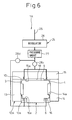
- Fig. 6 is a sectional view similarly illustrating the method of assembling the air bearing, and shows a state where one valve is opened and the other valve is closed,
- Fig. 7 is a sectional view similarly illustrating the method of assembling the air bearing, and shows a state where two valves are opened to pass compressed air, and
- Fig. 8 is a sectional view illustrating a conventional air bearing.
- A first embodiment of the air bearing according to the present invention will now be described with reference to Fig. 1. The air bearing of this embodiment is constituted by a base that is not shown, a
guide 2 fixed to the base, aslider 12 on the moving side float-supported so as to be able to move relative to theguide 12, and air-supplying means for supplying compressed air into between the opposing surfaces of theguide 2 and of theslider 12. - The
guide 2 extends straight to guide theslider 12, and is fixed to the base of a machine tool or measuring equipment that is not shown. Theguide 2 is of a right-and-left symmetrical shape, and has bearing surfaces (two pairs of opposing surfaces) 3 to 6 on the upper and lower surfaces and on the right and left side surfaces. The upper bearingsurfaces 5 are arranged on both sides of agroove 9, and the right and left bearingsurfaces portions 7. - Referring to Fig. 2,
magnets 8 are provided in the right and leftrecessed portions 7 for bringing thebearing surfaces guide 2 into close contact with theopposing surfaces slider 12. Themagnets 8 are for bringing thebearing surfaces opposing surfaces slider 12 with a weak magnetic force in a step prior to adjusting bearing gaps 10 (Figs. 3 and 4) of the air bearing. Thebearing surfaces opposing surfaces guide 2 to easily adjust thebearing gaps 10 as will be described later. - The
bearing surface 5 formed on the upper side of theguide 2 comes into sliding contact with theopposing surfaces 15a of the upperopposing member 15 of theslider 12.Grooves bearing surfaces 5 and theopposing surfaces 15a to thereby form a non-contacting portion (see Fig. 2). Therefore, thebearing surfaces 5 and theopposing surfaces 15a come in contact at their both end portions while maintaining a good balance. Thebearing surface 6 formed on the lower side of theguide 2 come into sliding contact with theopposing surface 16a of the lower opposingmembers 16 of theslider 12. Thus, the upper and lower bearingsurfaces guide 2 come into sliding contact with the upper and loweropposing surfaces slider 12 to enhance rigidity of the air bearing in the up-and-down direction. - The
slider 12 has two pairs of opposingmembers 13 to 16 arranged being opposed to each other in two directions of theguide 2 at right angles with each other, i.e., in the up-and-down direction and in the right-and-left direction, theopposing members 13 to 16 being assembled like a frame by using a plurality of bolts 30 (Fig. 1). Depending upon the degree of fastening thebolts 30, theopposing members opposing members - That is, by loosely fastening the
bolts 30 in a manner that there is a play between thebolts 30 and theholes 31, the opposingmembers opposing members bolts 30 so that there is no play between thebolts 30 and theholes 31, the opposingmembers opposing members members bolts 30 and the internally threaded portions of theholes 31. In the firmly fixed state, the positions of the opposingmembers opposing members - In the state where the
opposing members bearing surfaces guide 2 and theopposing surfaces members opposing members slider 12 is float-supported on both the right and left sides of theguide 2 so as to allow it to move relative thereto. - The pair of right and left opposing
members flow paths regulator 26. Theflow paths opposing members bearing surfaces guide 2 and theopposing surfaces opposing members guide 2 and theslide 12, and supplied compressed air leaks through the gaps. By taking the leakage into consideration, compressed air of the predetermined pressure is supplied through theflow paths - The air-supplying means is constituted by a
pipe 25 for supplying the air, theregulator 26 for adjusting the pressure of the supplied air, apressure gauge 27 for measuring the air pressure, and twovalves regulator 26 and thepressure gauge 27 are arranged in the path way before compressed air is supplied to theslider 12, and it is allowed to supply the air to theslider 12 while making sure the pressure of compressed air that is supplied. The air flowing through theregulator 26 and thepressure gauge 27 is divided into two paths and is supplied through thevalves members - Next, a method of assembling an air bearing according to the embodiment will be described with reference to Figs. 2 to 4. Referring to Fig. 2, the air bearing is so constituted that the
slide 12 surrounds theguide 2. Both side surfaces of theguide 2 are thebearing surfaces slider 12. Compressed air has been shut off by theregulator 26. Of the pair of right and left opposingmembers member 13 of the left side is firmly fixed to the upper and lower opposingmembers member 14 of the right side is tentatively fixed to the upper and lower opposingmembers member 14 of the right side has thebolts 30 loosely tightened, and is allowed to move in the right-and-left direction by an amount corresponding to a play between the externally threaded portions of thebolts 30 and the internally threaded portions in the opposingmembers - In this state, one opposing
member 13 is brought into close contact with the bearingsurface 3 on the left side of theguide 2 due to the attractive force of themagnet 8 incorporated in theguide 2, and the other opposingmember 14 is similarly brought into close contact with the bearingsurface 4 on the right side due to the attractive force of themagnet 8. - Referring to Fig. 3, if compressed air of the predetermined pressure is supplied through the
flow path 19 in one opposingmember 13, the pressure of compressed air works against the attractive force of themagnet 8 and the opposingsurface 13a of the one opposingmember 13 separates away from the bearingsurface 3 of theguide 2, and a gap is formed between the opposingsurface 13a and thebearing surface 3. The gap is set to be twice as great as the designedtarget bearing gap 10 of the air bearing structure. Upon measuring in advance the pressure of compressed air that is supplied, the size of the gap, which depends on the pressure of compressed air, can, thereafter, be reproduced without the need of taking a measurement. The other opposingmember 14 that is contacting to theguide 2 in this state due to the attractive force of themagnet 8 is firmly fixed to the pair of upper and lower opposingmembers bolts 30. - Referring next to Fig. 4, compressed air of a suitable pressure is supplied to between the opposing
surfaces members guide 2 through theflow paths members target bearing gaps 10 on both the right and left sides of theguide 2. - Next, the air bearing and the method of assembling the air bearing according to a second embodiment of the invention will be described with reference to Figs. 5 to 7. The air bearing (Fig. 7) 1A of this embodiment forms the
same bearing gaps 10 between theguide 2 and the pair of opposingmembers guide 2, making a difference from the air baring (Fig. 1) 1 of the first embodiment that forms thesame bearing gaps 10 between theguide 2 and the pair of opposingmembers guide 2. Constituent portions overlapping between theair bearing 1A of this embodiment and theair bearing 1 of the first embodiment are denoted by the same reference numerals, but their description is not repeated. - Referring to Fig. 5, gaps have been formed in advance on both sides of the
guide 2 in the right-and-left direction. The pair of up and down opposingmembers flow paths guide 2. Theregulator 26 and thepressure gauge 27 are arranged on the way before compressed air is supplied to the opposingmembers members - The pair of upper and lower opposing
members members members bolts 30 stay loosened, the opposingmembers bolts 30 and the internally threaded portions, and the opposing gap can be finely adjusted. - Fig. 5 illustrates a state where compressed air is shut off by the
regulator 26. Of the pair of upper and lower opposingmembers member 15 is firmly fixed bybolts 30 to the right and left opposingmembers member 16 is tentatively fixed to the right and left opposingmembers member 16 is temporarily fixed in a state where thebolts 30 stay loosened, and is allowed to move up and down by an amount corresponding to a play between the externally threaded portions of thebolts 30 and the internally threaded portions of the opposingmembers - The upper opposing
member 15 is closely contacting to thebearing surface 5 of theguide 2 due to gravity. The lower opposingmember 16 is in a tentatively fixed state, i.e., is in a state where thebolts 30 are loosened and, therefore, is separated away downward due to gravity by an amount of play between the externally threaded portions of thebolts 30 and the internally threaded portions of the opposingmembers - In this state as shown in Fig. 6, if compressed air is supplied to the upper opposing
member 15, the upper opposingmember 15 moves upward overcoming the gravity due to the internal pressure of compressed air, and a gap is formed between the upper opposingmember 15 and theguide 2 in a state where the lower opposingmember 16 and theguide 2 are closely contacted together. The size of the gap varies depending upon the pressure of compressed air, and can be reproduced any number of times upon examining, in advance, a relationship between the size of the gap and the pressure. The pressure of compressed air is so adjusted that the gap becomes twice as great as the designed target bearing gap of the air bearing structure. After the gap is adjusted, the lower opposingmember 16 is firmly fixed to the pair of right and left opposingmembers - Referring to Fig. 7, compressed air of a predetermined pressure is supplied to between the pair of upper and lower opposing
members target bearing gaps 10 between theguide 2 and the opposingmembers guide 2. - The invention is in no way limited to the above embodiments only and can be put into practice being modified in a variety of ways without departing from the gist of the invention. For example, the methods of assembling the air bearing of the first embodiment and of the second embodiment may be combined together to form the designed
target bearing gaps 10 in two directions of theguide 2 at right angles with each other. Or, in the first embodiment, the pair of right and left opposingmembers magnets 8, so that theair bearing 1 works as a linear motor of a low drive resistance. - While the invention has been described with reference to specific embodiments chosen for purpose of illustration, it should be apparent that numerous modifications could be made thereto, by those skilled in the art, without departing from the basic concept and scope of the invention.
Claims (5)
- A method of assembling an air bearing (1, 1A), the air bearing (1, 1A) comprising a guide (2) on a fixed side, and a slider (12) having a pair of opposing members (13-16) arranged on opposite sides of the guide (2), the slider (12) being float-supported so as to be able to move relative to the guide (2),
characterized in that the method comprises:contacting a first opposing member (13, 15) of the pair of opposing members (13-16) to the guide (2),supplying compressed air of a predetermined pressure between the first opposing member (13, 15) and the guide (2) contacting each other, so as to form a temporary gap twice as large as a target bearing gap between the first opposing member (13, 15) and the guide (2);maintaining contact between the guide (2) and a second opposing member (14, 16) of the pair of opposing members (13-16); andsupplying compressed air of a predetermined pressure between the first opposing member (13, 15) and the guide (2) as well as the second opposing member (14, 16) and the guide (2), so as to form respective target bearing gaps between the first and second opposing members (13-16) and the guide (2), in place of the temporary gap. - A method of assembling an air bearing according to claim 1, during a contacting state of the first and second opposing members (13-16) and the guide (2), further comprising maintaining the contacting state by magnetic force.
- An air bearing (1, 1A) comprising:a guide (2) on a fixed side; anda slider (12) having a pair of opposing members (13-16) arranged on opposite sides of the guide (2), the slider (12) being float-supported so as to be able to move relative to the guide (2):characterized in that the guide and the slider are assembled together by a method according to claim 1.
- An air bearing (1A) according to claim 3, wherein other pair of opposing members (15, 16) is provided in a direction orthogonal to the pair of opposing members (13, 14), respective target bearing gaps are also formed between the other pair of opposing members (15, 16) and the guide (2).
- A linear drive unit wherein magnets are provided in either one of the opposing members (13-16) or the guide (2) of the air bearing (1, 1A) of claim 3, and drive coils are provided in the other one of the opposing members (13-16) or the guide (2) to form a magnetic field in cooperation with the magnets.
Applications Claiming Priority (1)
| Application Number | Priority Date | Filing Date | Title |
|---|---|---|---|
| JP2006000112A JP4047889B2 (en) | 2006-01-04 | 2006-01-04 | Method for assembling linear drive device with air bearing |
Publications (1)
| Publication Number | Publication Date |
|---|---|
| EP1806511A2 true EP1806511A2 (en) | 2007-07-11 |
Family
ID=37895901
Family Applications (1)
| Application Number | Title | Priority Date | Filing Date |
|---|---|---|---|
| EP06027014A Withdrawn EP1806511A2 (en) | 2006-01-04 | 2006-12-28 | Method of assembling air bearing, air bearing and linear drive unit equipped with the same |
Country Status (4)
| Country | Link |
|---|---|
| US (1) | US7651272B2 (en) |
| EP (1) | EP1806511A2 (en) |
| JP (1) | JP4047889B2 (en) |
| CN (1) | CN100476226C (en) |
Families Citing this family (16)
| Publication number | Priority date | Publication date | Assignee | Title |
|---|---|---|---|---|
| DE102008035949A1 (en) * | 2008-07-31 | 2010-02-04 | Etel S.A. | Clean room suitable linear guide |
| CN101769336B (en) * | 2009-01-05 | 2013-02-13 | 鸿富锦精密工业(深圳)有限公司 | air rail |
| CN101813130B (en) * | 2010-05-07 | 2012-05-23 | 浙江工业大学 | An air flotation device that follows the movement trajectory of the lifting point over a long distance and is not affected by the disturbance force of the trachea |
| CN102312921B (en) * | 2010-07-02 | 2013-05-29 | 东上国际股份有限公司 | Air Bearing Manufacturing Method |
| CN102444669B (en) * | 2010-10-15 | 2014-03-26 | 上海微电子装备有限公司 | Gas floating cushion for gas floating bearing |
| JP5928106B2 (en) * | 2012-04-02 | 2016-06-01 | オイレス工業株式会社 | Static pressure gas bearing and linear motion guide device using the static pressure gas bearing |
| JP5532175B1 (en) * | 2013-07-02 | 2014-06-25 | 日本精工株式会社 | Table device and transfer device |
| CN103697293B (en) * | 2013-12-12 | 2016-04-20 | 上海通用金属结构工程有限公司 | The installation method of precision bearing workshop equipment |
| CN103706489B (en) * | 2013-12-12 | 2015-09-23 | 上海通用金属结构工程有限公司 | High speed centrifugation separation equipment installation method |
| CN103899644B (en) * | 2014-03-12 | 2016-11-23 | 哈尔滨工程大学 | Staged composite throttling air-float guide rail |
| JP7062885B2 (en) * | 2017-05-19 | 2022-05-09 | 株式会社ジェイテクト | Machine tool equipped with static pressure slide guide device and static pressure slide guide device |
| US10704598B1 (en) * | 2019-03-05 | 2020-07-07 | Hiwin Technologies Corp. | Hydrostatic linear guideway |
| CN111156249B (en) * | 2020-02-26 | 2024-11-05 | 中国工程物理研究院机械制造工艺研究所 | An air-floating guide rail with adjustable stiffness |
| CN116292628B (en) * | 2023-03-21 | 2025-09-19 | 江苏集萃精凯高端装备技术有限公司 | Air-float guide rail device with gap adjusting function and using method thereof |
| CN118423367B (en) * | 2024-07-05 | 2024-10-01 | 迈为技术(珠海)有限公司 | Air floating guide rail device and guide rail gap adjustment method |
| CN119216616B (en) * | 2024-09-20 | 2025-03-07 | 浙江求是半导体设备有限公司 | Air spindle and its adjustment method |
Family Cites Families (25)
| Publication number | Priority date | Publication date | Assignee | Title |
|---|---|---|---|---|
| JPS6043723U (en) | 1983-09-02 | 1985-03-27 | 東陶機器株式会社 | slider |
| JPS6125742A (en) * | 1984-07-11 | 1986-02-04 | Ntn Toyo Bearing Co Ltd | Guide device |
| JPS61209838A (en) * | 1985-03-12 | 1986-09-18 | Omron Tateisi Electronics Co | Single shaft stage |
| JPS6235113A (en) | 1985-08-08 | 1987-02-16 | Omron Tateisi Electronics Co | Static pressure bearing device |
| JPS6235112A (en) | 1985-08-08 | 1987-02-16 | Omron Tateisi Electronics Co | Hydrostatic bearing device |
| JPS6237514A (en) | 1985-08-10 | 1987-02-18 | Omron Tateisi Electronics Co | Static pressure bearing device |
| JPS63231019A (en) | 1987-03-19 | 1988-09-27 | Canon Inc | Hydrostatic bearing device |
| JPH01288615A (en) | 1988-05-14 | 1989-11-20 | Matsushita Electric Works Ltd | Static pressure bearing device |
| JPH0215837A (en) | 1988-07-04 | 1990-01-19 | Canon Inc | Aligning method for piercing device |
| DE3823978A1 (en) * | 1988-07-15 | 1990-01-18 | Skf Linearsysteme Gmbh | LINEAR GUIDE FOR PRECISION MACHINES |
| JPH04145219A (en) * | 1990-10-05 | 1992-05-19 | Nec Corp | Air bearing type guide |
| JPH04236303A (en) * | 1991-01-18 | 1992-08-25 | Ricoh Co Ltd | Gap measurement method and measuring device for hydrodynamic air bearings |
| JP3492706B2 (en) * | 1991-10-14 | 2004-02-03 | 松下電器産業株式会社 | Air bearing type linear motor device |
| JPH06264923A (en) * | 1993-03-12 | 1994-09-20 | Yamazaki Mazak Corp | Direct-acting guide device |
| US5650679A (en) * | 1993-03-18 | 1997-07-22 | Boggs, Iii; Paul Dewey | Eddy current drive |
| JPH06341435A (en) | 1993-05-31 | 1994-12-13 | Sony Corp | Air static pressure bearing device |
| JPH0828565A (en) | 1994-07-18 | 1996-02-02 | Sony Corp | Hydrostatic gas bearing |
| JPH08323567A (en) * | 1995-05-31 | 1996-12-10 | Ntn Corp | XY table |
| JPH1026139A (en) | 1996-07-09 | 1998-01-27 | Nippon Seiko Kk | Linear gas bearing |
| JPH10246228A (en) | 1997-03-03 | 1998-09-14 | Nikon Corp | Hydrostatic gas bearing and stage device using the same |
| JP3911064B2 (en) * | 1997-04-15 | 2007-05-09 | Ntn株式会社 | Air slide device |
| US6623251B2 (en) * | 1999-06-21 | 2003-09-23 | Nsk Ltd. | Spindle apparatus |
| JP2001126651A (en) * | 1999-10-22 | 2001-05-11 | Hitachi Ltd | Electron beam lithography system |
| JP2004317243A (en) * | 2003-04-15 | 2004-11-11 | Mitsutoyo Corp | Measuring machine |
| US20050057102A1 (en) * | 2003-09-11 | 2005-03-17 | Nikon Corporation | Holding member, coolant, cooling method and cooling device, linear motor device, stage device, and exposure apparatus |
-
2006
- 2006-01-04 JP JP2006000112A patent/JP4047889B2/en not_active Expired - Fee Related
- 2006-12-28 EP EP06027014A patent/EP1806511A2/en not_active Withdrawn
- 2006-12-30 CN CNB2006101566981A patent/CN100476226C/en not_active Expired - Fee Related
-
2007
- 2007-01-03 US US11/619,503 patent/US7651272B2/en active Active
Also Published As
| Publication number | Publication date |
|---|---|
| US20070154120A1 (en) | 2007-07-05 |
| CN100476226C (en) | 2009-04-08 |
| JP4047889B2 (en) | 2008-02-13 |
| JP2007182911A (en) | 2007-07-19 |
| US7651272B2 (en) | 2010-01-26 |
| CN1995771A (en) | 2007-07-11 |
Similar Documents
| Publication | Publication Date | Title |
|---|---|---|
| US7651272B2 (en) | Method of assembling air bearing, air bearing and linear drive unit equipped with the same | |
| US6911747B2 (en) | X-Y stage system with onboard linear motor | |
| US5234386A (en) | Actuator and actuator arrangement | |
| US20080304772A1 (en) | Hydrostatic guide system | |
| CN101743423A (en) | Electronically controlled valve and systems containing same | |
| EP1632953B1 (en) | Supporting unit, and moving table device and linear-motion guiding device using the supporting unit | |
| US8008815B2 (en) | Planar stage moving apparatus for machine | |
| JP4938014B2 (en) | Hydrostatic rail guide | |
| JP3636435B2 (en) | Simplified torque motor | |
| CN111195828A (en) | Direct-acting mechanism, balancing device and machine tool | |
| US8282282B2 (en) | Motion guide device and method of assembling motion guide device | |
| JP2006084355A (en) | Stage guide mechanism | |
| EP2037136A2 (en) | Fluid bearing structure and assembly method for fluid bearing structure | |
| US5669600A (en) | X-Y table | |
| US20230018583A1 (en) | High precision machine tool having linear drive-and guide bearing | |
| JP4106392B2 (en) | Gas pressure control actuator, gas bearing mechanism for gas pressure control actuator, and minute displacement output device using gas pressure control actuator | |
| KR100648492B1 (en) | Bonding device | |
| JP2513374B2 (en) | Orthogonal bidirectional movement table device | |
| JPH0546864Y2 (en) | ||
| CN120704078B (en) | An ultra-precision air-floating motion platform | |
| US20140366663A1 (en) | Aerostatic air bearing, assembling method thereof, and aerostatic lead screw actuator using the same | |
| JP2007218354A (en) | High speed open / close double seat valve device for fluid supply | |
| JP2013194816A (en) | Air guide device | |
| JPH086747B2 (en) | Inspection equipment | |
| Smith | Precision machine principles and elements |
Legal Events
| Date | Code | Title | Description |
|---|---|---|---|
| PUAI | Public reference made under article 153(3) epc to a published international application that has entered the european phase |
Free format text: ORIGINAL CODE: 0009012 |
|
| AK | Designated contracting states |
Kind code of ref document: A2 Designated state(s): AT BE BG CH CY CZ DE DK EE ES FI FR GB GR HU IE IS IT LI LT LU LV MC NL PL PT RO SE SI SK TR |
|
| AX | Request for extension of the european patent |
Extension state: AL BA HR MK YU |
|
| STAA | Information on the status of an ep patent application or granted ep patent |
Free format text: STATUS: THE APPLICATION HAS BEEN WITHDRAWN |
|
| 18W | Application withdrawn |
Effective date: 20100825 |