EP1806246A1 - Compact circuit board for an automotive HVAC system - Google Patents
Compact circuit board for an automotive HVAC system Download PDFInfo
- Publication number
- EP1806246A1 EP1806246A1 EP06077271A EP06077271A EP1806246A1 EP 1806246 A1 EP1806246 A1 EP 1806246A1 EP 06077271 A EP06077271 A EP 06077271A EP 06077271 A EP06077271 A EP 06077271A EP 1806246 A1 EP1806246 A1 EP 1806246A1
- Authority
- EP
- European Patent Office
- Prior art keywords
- base
- leg
- circuit board
- set forth
- housing
- Prior art date
- Legal status (The legal status is an assumption and is not a legal conclusion. Google has not performed a legal analysis and makes no representation as to the accuracy of the status listed.)
- Withdrawn
Links
Images

Classifications
-
- H—ELECTRICITY
- H05—ELECTRIC TECHNIQUES NOT OTHERWISE PROVIDED FOR
- H05K—PRINTED CIRCUITS; CASINGS OR CONSTRUCTIONAL DETAILS OF ELECTRIC APPARATUS; MANUFACTURE OF ASSEMBLAGES OF ELECTRICAL COMPONENTS
- H05K1/00—Printed circuits
- H05K1/18—Printed circuits structurally associated with non-printed electric components
- H05K1/189—Printed circuits structurally associated with non-printed electric components characterised by the use of flexible or folded printed circuits
-
- B—PERFORMING OPERATIONS; TRANSPORTING
- B60—VEHICLES IN GENERAL
- B60H—ARRANGEMENTS OF HEATING, COOLING, VENTILATING OR OTHER AIR-TREATING DEVICES SPECIALLY ADAPTED FOR PASSENGER OR GOODS SPACES OF VEHICLES
- B60H1/00—Heating, cooling or ventilating devices
- B60H1/00507—Details, e.g. mounting arrangements, desaeration devices
- B60H1/00514—Details of air conditioning housings
- B60H1/00521—Mounting or fastening of components in housings, e.g. heat exchangers, fans, electronic regulators
-
- B—PERFORMING OPERATIONS; TRANSPORTING
- B60—VEHICLES IN GENERAL
- B60H—ARRANGEMENTS OF HEATING, COOLING, VENTILATING OR OTHER AIR-TREATING DEVICES SPECIALLY ADAPTED FOR PASSENGER OR GOODS SPACES OF VEHICLES
- B60H1/00—Heating, cooling or ventilating devices
- B60H1/00507—Details, e.g. mounting arrangements, desaeration devices
- B60H2001/00614—Cooling of electronic units in air stream
-
- H—ELECTRICITY
- H05—ELECTRIC TECHNIQUES NOT OTHERWISE PROVIDED FOR
- H05K—PRINTED CIRCUITS; CASINGS OR CONSTRUCTIONAL DETAILS OF ELECTRIC APPARATUS; MANUFACTURE OF ASSEMBLAGES OF ELECTRICAL COMPONENTS
- H05K2201/00—Indexing scheme relating to printed circuits covered by H05K1/00
- H05K2201/04—Assemblies of printed circuits
- H05K2201/042—Stacked spaced PCBs; Planar parts of folded flexible circuits having mounted components in between or spaced from each other
Definitions
- HVAC heat, ventilation and air conditioning
- the electrical control module employed in HVAC systems are usually resistor devices for controlling the blower motor and are disposed so as to extend into an air passage defined by housing, the blower motor being supported in the housing.
- the electrical control module comprises a base supported by the housing and a circuit board having spaced side edges and extends into the housing from the base. An electrical circuit is disposed on the circuit board for controlling the motor.
- Such an electrical control module is shown in U.S. Patents 5,268,665 to Iwao and Des. 340,223 to Nitta et al.
- the known electrical control modules typically include a screenprinted resistance circuit on a rectangular shaped circuit board.
- the circuit board is disposed in the air flow path in a passage in the HVAC housing to dissipate heat and, sometimes, whistles and noises are generated by the air moving over the circuit board.
- the length of the rectangular shape to achieve the circuit lengths increases packaging space thereby increasing shipping expenses.
- the invention provides for the circuit board having a first leg extending from the base and through a curved section and into a second leg to a distal end with the electrical circuit extending over the first leg and over the curved section and over the second leg.
- the circuit board of the subject invention can be packed more densely to reduce shipping expense and can be shaped to minimize air flow generated noises.
- HVAC heat, ventilation and air conditioning
- the system 20 includes an electrical control module 30 generally indicated.
- the module 30 includes a base 32 supported by the housing 22 with attachments 34 for removably attaching the base 32 to the housing 22. More specifically, as illustrated, the attachments 34 comprise flanges through which fasteners extend for securing the module 30 to the housing 22.
- the attachments 34 may also comprise mechanical snap-together connectors.
- the invention is distinguished by the circuit board 36 having a first leg 40 extending from the base 32 and through a curved section 42 and into a second leg 44 to a distal end spaced from the base 32.
- the electrical circuit 38 extends over the first leg 40 and over the curved section 42 and over the second leg 44.
- the circuit board 36 includes an interior surface and an exterior surface and the electrical circuit 38 is disposed on the exterior surface.
- the second leg 44 is substantially parallel to the first leg 40 and the circuit board 36 includes an offset section 46 between the base 32 and the first leg 40 for centralizing the legs 40, 44 on the base 32.
- the base 32 includes an electrical connector 48 for connection to an electrical plug.
- the electrical connector 48 is illustrated as a female socket having male prongs for receiving a male plug having female prong openings.
- a heat exchanger is supported in a portion 50 of the housing 22 for receiving air from the passage 24 and the circuit board 36 is disposed in the passage 24 with the side edges aligned with the flow path, as best shown in Figure 3.
Landscapes
- Engineering & Computer Science (AREA)
- Microelectronics & Electronic Packaging (AREA)
- Physics & Mathematics (AREA)
- Thermal Sciences (AREA)
- Mechanical Engineering (AREA)
- Air-Conditioning For Vehicles (AREA)
Abstract
Description
- An automotive heat, ventilation and air conditioning (HVAC) system including an electrical control module having a circuit board in the air flow.
- The electrical control module employed in HVAC systems are usually resistor devices for controlling the blower motor and are disposed so as to extend into an air passage defined by housing, the blower motor being supported in the housing. The electrical control module comprises a base supported by the housing and a circuit board having spaced side edges and extends into the housing from the base. An electrical circuit is disposed on the circuit board for controlling the motor. Such an electrical control module is shown in
U.S. Patents 5,268,665 to Iwao and Des.340,223 to Nitta et al. - The known electrical control modules typically include a screenprinted resistance circuit on a rectangular shaped circuit board. The circuit board is disposed in the air flow path in a passage in the HVAC housing to dissipate heat and, sometimes, whistles and noises are generated by the air moving over the circuit board. In addition, the length of the rectangular shape to achieve the circuit lengths increases packaging space thereby increasing shipping expenses.
- The invention provides for the circuit board having a first leg extending from the base and through a curved section and into a second leg to a distal end with the electrical circuit extending over the first leg and over the curved section and over the second leg.
- Accordingly, the circuit board of the subject invention can be packed more densely to reduce shipping expense and can be shaped to minimize air flow generated noises.
- Other advantages of the present invention will be readily appreciated, as the same becomes better understood by reference to the following detailed description when considered in connection with the accompanying drawings wherein:
- Figure 1 is a bottom view of a HVAC system showing the electrical control module;
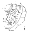
- Figure 2 is an enlarged fragmentary perspective view of the HVAC system showing the electrical control module;
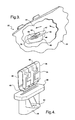
- Figure 3 is an enlarged fragmentary view showing the electrical control module supported by the housing in the air flow path; and
- Figure 4 is a perspective view of the electrical control module.
- Referring to the Figures, wherein like numerals indicate corresponding parts throughout the several views, an automotive heat, ventilation and air conditioning (HVAC)
system 20 is generally shown and includes ahousing 22 defining anair passage 24, as shown in Figure 3. Amotor 26 is supported in thehousing 22 and drives a blower for blowing air in a flow path along thepassage 24 defining ascroll 28. - The
system 20 includes anelectrical control module 30 generally indicated. Themodule 30 includes abase 32 supported by thehousing 22 withattachments 34 for removably attaching thebase 32 to thehousing 22. More specifically, as illustrated, theattachments 34 comprise flanges through which fasteners extend for securing themodule 30 to thehousing 22. Theattachments 34 may also comprise mechanical snap-together connectors. - A
circuit board 36, having spaced side edges, and extends into thehousing 22 from thebase 32 and anelectrical circuit 38 is disposed on thecircuit board 36 for controlling themotor 26, theelectrical circuit 38 being a resistance circuit. Theelectrical circuit 38 over the curved surface is applied by a micro-pen resistive ink depositing process. - The invention is distinguished by the
circuit board 36 having afirst leg 40 extending from thebase 32 and through acurved section 42 and into asecond leg 44 to a distal end spaced from thebase 32. Theelectrical circuit 38 extends over thefirst leg 40 and over thecurved section 42 and over thesecond leg 44. More specifically, thecircuit board 36 includes an interior surface and an exterior surface and theelectrical circuit 38 is disposed on the exterior surface. In the preferred embodiment, thesecond leg 44 is substantially parallel to thefirst leg 40 and thecircuit board 36 includes anoffset section 46 between thebase 32 and thefirst leg 40 for centralizing thelegs base 32. - The
base 32 includes anelectrical connector 48 for connection to an electrical plug. Theelectrical connector 48 is illustrated as a female socket having male prongs for receiving a male plug having female prong openings. - A heat exchanger is supported in a
portion 50 of thehousing 22 for receiving air from thepassage 24 and thecircuit board 36 is disposed in thepassage 24 with the side edges aligned with the flow path, as best shown in Figure 3. - Obviously, many modifications and variations of the present invention are possible in light of the above teachings. The invention may be practiced otherwise than as specifically described within the scope of the appended claims
Claims (14)
- An automotive heat, ventilation and air conditioning (HVAC) system (20) comprising;
a housing (22) defining an air passage (24),
a blower motor (26) supported in said housing (22),
a base (32) supported by said housing (22),
a circuit board (36) having spaced side edges and extending into said housing (22) from said base (32),
an electrical circuit (38) disposed on said circuit board (36) for controlling said motor (26), and
characterized by said circuit board (36) having a first leg (40) extending from said base (32) and through a curved section (42) and into a second leg (44) to a distal end, said electrical circuit (38) extending over said first leg (40) and over said curved section (42) and over said second leg (44). - A system (20) as set forth in claim 1 wherein said circuit board (36) includes an interior surface and an exterior surface and said electrical circuit (38) is disposed on said exterior surface.
- A system (20) as set forth in claim 1 wherein said second leg (44) is substantially parallel to said first leg (40).
- A system (20) as set forth in claim 1 including a blower for blowing air in a flow path along said passage (24), said circuit board (36) disposed in said passage (24) with said side edges aligned with said flow path.
- A system (20) as set forth in claim 1 wherein said base (32) includes an electrical connector (48) for connection to an electrical plug.
- A system (20) as set forth in claim 1 wherein said base (32) includes attachments (34) for removably attaching said base (32) to said housing (22).
- A system (20) as set forth in claim 1 including a heat exchanger supported in said housing (22) for receiving air from said passage (24).
- A system (20) as set forth in claim 1 wherein said circuit board (36) includes an offset section (46) between said base (32) and said first leg (40) for centralizing said legs (40, 44) on said base (32).
- An electrical control module (30) comprising;
a base (32),
a circuit board (36) having spaced side edges and extending from said base (32),
an electrical circuit (38) disposed on said circuit board (36), and
characterized by said circuit board (36) having a first leg (40) extending from said base (32) and through a curved section (42) and into a second leg (44) to a distal end, said electrical circuit (38) extending over said first leg (40) and over said curved section (42) and over said second leg (44). - A module (30) as set forth in claim 9 wherein said circuit board (36) includes an interior surface and an exterior surface and said electrical circuit (38) is disposed on said exterior surface.
- A module (30) as set forth in claim 9 wherein said second leg (44) is substantially parallel to said first leg (40).
- A module (30) as set forth in claim 9 wherein said base (32) includes an electrical connector (48) for connection to an electrical plug.
- A module (30) as set forth in claim 12 wherein said base (32) includes attachments (34) for removably attaching said base (32) to said housing (22).
- A module (30) as set forth in claim 9 wherein said circuit board (36) includes an offset section (46) between said base (32) and said first leg (40) for centralizing said legs (40, 44) on said base (32).
Applications Claiming Priority (1)
| Application Number | Priority Date | Filing Date | Title |
|---|---|---|---|
| US11/328,290 US7543632B2 (en) | 2006-01-09 | 2006-01-09 | Compact circuit board for an automotive HVAC system |
Publications (1)
| Publication Number | Publication Date |
|---|---|
| EP1806246A1 true EP1806246A1 (en) | 2007-07-11 |
Family
ID=37946412
Family Applications (1)
| Application Number | Title | Priority Date | Filing Date |
|---|---|---|---|
| EP06077271A Withdrawn EP1806246A1 (en) | 2006-01-09 | 2006-12-18 | Compact circuit board for an automotive HVAC system |
Country Status (3)
| Country | Link |
|---|---|
| US (1) | US7543632B2 (en) |
| EP (1) | EP1806246A1 (en) |
| JP (1) | JP2007238077A (en) |
Cited By (1)
| Publication number | Priority date | Publication date | Assignee | Title |
|---|---|---|---|---|
| US10215436B1 (en) | 2011-05-02 | 2019-02-26 | John M. Rawski | Full spectrum universal controller |
Families Citing this family (1)
| Publication number | Priority date | Publication date | Assignee | Title |
|---|---|---|---|---|
| US20160039372A1 (en) * | 2014-08-05 | 2016-02-11 | Air International (Us) Inc. | Actuator retainer |
Citations (8)
| Publication number | Priority date | Publication date | Assignee | Title |
|---|---|---|---|---|
| US340223A (en) | 1886-04-20 | Maurice l epine | ||
| US3766439A (en) * | 1972-01-12 | 1973-10-16 | Gen Electric | Electronic module using flexible printed circuit board with heat sink means |
| CH583499A5 (en) * | 1975-04-03 | 1976-12-31 | Landis & Gyr Ag | Circuit board support assembly - has flexible board carrying connections for plug in boards and cables |
| US4781601A (en) * | 1987-07-06 | 1988-11-01 | Motorola, Inc. | Header for an electronic circuit |
| US4843520A (en) * | 1987-02-03 | 1989-06-27 | Matsushita Electric Industrial Co. Ltd. | Electronic circuit module |
| US5268665A (en) | 1990-11-26 | 1993-12-07 | Pacific Engineering Co., Ltd. | Resistor device for blower motor |
| EP1014580A2 (en) * | 1998-12-21 | 2000-06-28 | Valeo Schalter und Sensoren GmbH | Method for measuring the delay between two periodic pulse signals of the same frequency |
| US6747542B1 (en) | 2000-08-14 | 2004-06-08 | Delphi Technologies, Inc. | Snap-in blow motor speed control with brakeaway service feature |
Family Cites Families (4)
| Publication number | Priority date | Publication date | Assignee | Title |
|---|---|---|---|---|
| KR920000868Y1 (en) * | 1988-07-08 | 1992-01-31 | 지이제루 기기 가부시기가이샤 | Control device for a blower |
| USD340223S (en) * | 1990-05-21 | 1993-10-12 | Taisei Co., Ltd. | Control resistor for an automobile blower motor |
| US5408575A (en) * | 1992-06-01 | 1995-04-18 | International Resistive Company, Inc. | Automotive fan controller |
| JPH09240250A (en) * | 1995-12-27 | 1997-09-16 | Karusonitsuku Prod Kk | Resistor |
-
2006
- 2006-01-09 US US11/328,290 patent/US7543632B2/en not_active Expired - Fee Related
- 2006-12-18 EP EP06077271A patent/EP1806246A1/en not_active Withdrawn
-
2007
- 2007-01-09 JP JP2007001051A patent/JP2007238077A/en active Pending
Patent Citations (8)
| Publication number | Priority date | Publication date | Assignee | Title |
|---|---|---|---|---|
| US340223A (en) | 1886-04-20 | Maurice l epine | ||
| US3766439A (en) * | 1972-01-12 | 1973-10-16 | Gen Electric | Electronic module using flexible printed circuit board with heat sink means |
| CH583499A5 (en) * | 1975-04-03 | 1976-12-31 | Landis & Gyr Ag | Circuit board support assembly - has flexible board carrying connections for plug in boards and cables |
| US4843520A (en) * | 1987-02-03 | 1989-06-27 | Matsushita Electric Industrial Co. Ltd. | Electronic circuit module |
| US4781601A (en) * | 1987-07-06 | 1988-11-01 | Motorola, Inc. | Header for an electronic circuit |
| US5268665A (en) | 1990-11-26 | 1993-12-07 | Pacific Engineering Co., Ltd. | Resistor device for blower motor |
| EP1014580A2 (en) * | 1998-12-21 | 2000-06-28 | Valeo Schalter und Sensoren GmbH | Method for measuring the delay between two periodic pulse signals of the same frequency |
| US6747542B1 (en) | 2000-08-14 | 2004-06-08 | Delphi Technologies, Inc. | Snap-in blow motor speed control with brakeaway service feature |
Cited By (1)
| Publication number | Priority date | Publication date | Assignee | Title |
|---|---|---|---|---|
| US10215436B1 (en) | 2011-05-02 | 2019-02-26 | John M. Rawski | Full spectrum universal controller |
Also Published As
| Publication number | Publication date |
|---|---|
| US20070161286A1 (en) | 2007-07-12 |
| JP2007238077A (en) | 2007-09-20 |
| US7543632B2 (en) | 2009-06-09 |
Similar Documents
| Publication | Publication Date | Title |
|---|---|---|
| JP3058389U (en) | Radiator for electronic products | |
| US20040238651A1 (en) | Function transform sub-base | |
| US6705671B1 (en) | Electronically integrated vehicle support structure | |
| CN105794044B (en) | Installable cable interface | |
| WO2012133497A1 (en) | Fan chassis, fan unit, and communication device | |
| WO2005021076A3 (en) | Heater for ventilator conduit | |
| CN201263265Y (en) | Ventilated shielding dustproof panel | |
| WO2003007678A3 (en) | Fail safe cooling system | |
| JP2007205357A (en) | Ventilation fan of electrical and electronic devices | |
| US6991496B2 (en) | Electrical connector | |
| CN109515348B (en) | Electronic unit for vehicle | |
| HK1047616A1 (en) | Air conditioner and method of installing the air conditioner | |
| US7543632B2 (en) | Compact circuit board for an automotive HVAC system | |
| CN112009202B (en) | Heating device | |
| CN107725413A (en) | Blower fan | |
| CN102811585A (en) | Electronic device | |
| CN102089169B (en) | Ventilation module for vehicle roof-mounted systems | |
| WO2011131684A1 (en) | A thermally controlled assembly | |
| JP4219231B2 (en) | Air conditioner | |
| EP1804037A3 (en) | System with thermal type air flow measuring instrument for internal combustion engine | |
| CN101295898A (en) | Fan and its plug | |
| CN216346940U (en) | Air conditioner electric control box and air conditioner | |
| US6747542B1 (en) | Snap-in blow motor speed control with brakeaway service feature | |
| WO2018038953A1 (en) | Sensor mounting assembly for a climate controller and method | |
| CN215435910U (en) | Driver of automobile heating ventilation air conditioner |
Legal Events
| Date | Code | Title | Description |
|---|---|---|---|
| PUAI | Public reference made under article 153(3) epc to a published international application that has entered the european phase |
Free format text: ORIGINAL CODE: 0009012 |
|
| AK | Designated contracting states |
Kind code of ref document: A1 Designated state(s): AT BE BG CH CY CZ DE DK EE ES FI FR GB GR HU IE IS IT LI LT LU LV MC NL PL PT RO SE SI SK TR |
|
| AX | Request for extension of the european patent |
Extension state: AL BA HR MK YU |
|
| 17P | Request for examination filed |
Effective date: 20080111 |
|
| 17Q | First examination report despatched |
Effective date: 20080215 |
|
| AKX | Designation fees paid |
Designated state(s): AT BE BG CH CY CZ DE DK EE ES FI FR GB GR HU IE IS IT LI LT LU LV MC NL PL PT RO SE SI SK TR |
|
| GRAP | Despatch of communication of intention to grant a patent |
Free format text: ORIGINAL CODE: EPIDOSNIGR1 |
|
| STAA | Information on the status of an ep patent application or granted ep patent |
Free format text: STATUS: THE APPLICATION IS DEEMED TO BE WITHDRAWN |
|
| 18D | Application deemed to be withdrawn |
Effective date: 20100720 |