EP1806173B1 - Flat membrane element and regeneration method thereof - Google Patents
Flat membrane element and regeneration method thereof Download PDFInfo
- Publication number
- EP1806173B1 EP1806173B1 EP06026612A EP06026612A EP1806173B1 EP 1806173 B1 EP1806173 B1 EP 1806173B1 EP 06026612 A EP06026612 A EP 06026612A EP 06026612 A EP06026612 A EP 06026612A EP 1806173 B1 EP1806173 B1 EP 1806173B1
- Authority
- EP
- European Patent Office
- Prior art keywords
- membrane sheet
- membrane
- laser
- support plate
- sheet
- Prior art date
- Legal status (The legal status is an assumption and is not a legal conclusion. Google has not performed a legal analysis and makes no representation as to the accuracy of the status listed.)
- Not-in-force
Links
- 239000012528 membrane Substances 0.000 title claims description 156
- 238000011069 regeneration method Methods 0.000 title claims description 21
- 238000010521 absorption reaction Methods 0.000 claims description 13
- 239000000463 material Substances 0.000 claims description 11
- 229920003002 synthetic resin Polymers 0.000 claims description 9
- 239000000057 synthetic resin Substances 0.000 claims description 9
- 239000007788 liquid Substances 0.000 claims description 6
- 230000008021 deposition Effects 0.000 claims description 5
- 238000001914 filtration Methods 0.000 claims description 5
- 239000000049 pigment Substances 0.000 claims description 3
- 238000000926 separation method Methods 0.000 claims description 2
- XLYOFNOQVPJJNP-UHFFFAOYSA-N water Substances O XLYOFNOQVPJJNP-UHFFFAOYSA-N 0.000 description 20
- 239000000047 product Substances 0.000 description 17
- 238000000034 method Methods 0.000 description 12
- 230000008929 regeneration Effects 0.000 description 10
- 239000000853 adhesive Substances 0.000 description 6
- 230000001070 adhesive effect Effects 0.000 description 6
- 238000004519 manufacturing process Methods 0.000 description 5
- 239000000706 filtrate Substances 0.000 description 3
- 230000001172 regenerating effect Effects 0.000 description 3
- 230000002349 favourable effect Effects 0.000 description 2
- 230000006870 function Effects 0.000 description 2
- 239000002440 industrial waste Substances 0.000 description 2
- 230000035515 penetration Effects 0.000 description 2
- 238000003825 pressing Methods 0.000 description 2
- 238000007665 sagging Methods 0.000 description 2
- 238000000108 ultra-filtration Methods 0.000 description 2
- 239000002033 PVDF binder Substances 0.000 description 1
- 239000004698 Polyethylene Substances 0.000 description 1
- 230000000903 blocking effect Effects 0.000 description 1
- 239000006229 carbon black Substances 0.000 description 1
- 230000015556 catabolic process Effects 0.000 description 1
- 238000011109 contamination Methods 0.000 description 1
- 238000005520 cutting process Methods 0.000 description 1
- 238000006731 degradation reaction Methods 0.000 description 1
- 230000007613 environmental effect Effects 0.000 description 1
- 230000004927 fusion Effects 0.000 description 1
- 238000002156 mixing Methods 0.000 description 1
- 229920002239 polyacrylonitrile Polymers 0.000 description 1
- -1 polyethylene Polymers 0.000 description 1
- 229920000573 polyethylene Polymers 0.000 description 1
- 229920002981 polyvinylidene fluoride Polymers 0.000 description 1
- 230000001681 protective effect Effects 0.000 description 1
- 230000009993 protective function Effects 0.000 description 1
- 239000000126 substance Substances 0.000 description 1
Images




Classifications
-
- B—PERFORMING OPERATIONS; TRANSPORTING
- B01—PHYSICAL OR CHEMICAL PROCESSES OR APPARATUS IN GENERAL
- B01D—SEPARATION
- B01D69/00—Semi-permeable membranes for separation processes or apparatus characterised by their form, structure or properties; Manufacturing processes specially adapted therefor
- B01D69/06—Flat membranes
-
- B—PERFORMING OPERATIONS; TRANSPORTING
- B01—PHYSICAL OR CHEMICAL PROCESSES OR APPARATUS IN GENERAL
- B01D—SEPARATION
- B01D63/00—Apparatus in general for separation processes using semi-permeable membranes
- B01D63/08—Flat membrane modules
- B01D63/081—Manufacturing thereof
-
- B—PERFORMING OPERATIONS; TRANSPORTING
- B01—PHYSICAL OR CHEMICAL PROCESSES OR APPARATUS IN GENERAL
- B01D—SEPARATION
- B01D65/00—Accessories or auxiliary operations, in general, for separation processes or apparatus using semi-permeable membranes
- B01D65/003—Membrane bonding or sealing
-
- B—PERFORMING OPERATIONS; TRANSPORTING
- B01—PHYSICAL OR CHEMICAL PROCESSES OR APPARATUS IN GENERAL
- B01D—SEPARATION
- B01D65/00—Accessories or auxiliary operations, in general, for separation processes or apparatus using semi-permeable membranes
- B01D65/02—Membrane cleaning or sterilisation ; Membrane regeneration
-
- B—PERFORMING OPERATIONS; TRANSPORTING
- B01—PHYSICAL OR CHEMICAL PROCESSES OR APPARATUS IN GENERAL
- B01D—SEPARATION
- B01D67/00—Processes specially adapted for manufacturing semi-permeable membranes for separation processes or apparatus
- B01D67/0081—After-treatment of organic or inorganic membranes
- B01D67/009—After-treatment of organic or inorganic membranes with wave-energy, particle-radiation or plasma
-
- B—PERFORMING OPERATIONS; TRANSPORTING
- B01—PHYSICAL OR CHEMICAL PROCESSES OR APPARATUS IN GENERAL
- B01D—SEPARATION
- B01D69/00—Semi-permeable membranes for separation processes or apparatus characterised by their form, structure or properties; Manufacturing processes specially adapted therefor
- B01D69/12—Composite membranes; Ultra-thin membranes
- B01D69/1216—Three or more layers
-
- B—PERFORMING OPERATIONS; TRANSPORTING
- B01—PHYSICAL OR CHEMICAL PROCESSES OR APPARATUS IN GENERAL
- B01D—SEPARATION
- B01D71/00—Semi-permeable membranes for separation processes or apparatus characterised by the material; Manufacturing processes specially adapted therefor
- B01D71/06—Organic material
-
- B—PERFORMING OPERATIONS; TRANSPORTING
- B01—PHYSICAL OR CHEMICAL PROCESSES OR APPARATUS IN GENERAL
- B01D—SEPARATION
- B01D2313/00—Details relating to membrane modules or apparatus
- B01D2313/04—Specific sealing means
-
- B—PERFORMING OPERATIONS; TRANSPORTING
- B01—PHYSICAL OR CHEMICAL PROCESSES OR APPARATUS IN GENERAL
- B01D—SEPARATION
- B01D2315/00—Details relating to the membrane module operation
- B01D2315/06—Submerged-type; Immersion type
-
- B—PERFORMING OPERATIONS; TRANSPORTING
- B01—PHYSICAL OR CHEMICAL PROCESSES OR APPARATUS IN GENERAL
- B01D—SEPARATION
- B01D2321/00—Details relating to membrane cleaning, regeneration, sterilization or to the prevention of fouling
-
- B—PERFORMING OPERATIONS; TRANSPORTING
- B01—PHYSICAL OR CHEMICAL PROCESSES OR APPARATUS IN GENERAL
- B01D—SEPARATION
- B01D2323/00—Details relating to membrane preparation
- B01D2323/58—Fusion; Welding
Definitions
- the present invention relates to a flat membrane element according to claim 1. Further, the present invention relates to a regeneration method of a flat membrane element.
- FIG. 7 is a partial sectional view showing a general structure of a flat membrane element.
- a support plate 1 is formed such that a circumferential edge 2 thereof has a flame shape and a water passing portion 3 is formed in the inner portion thereof.
- a membrane sheet 4 is attached onto both the faces of the support plate 1, respectively.
- a suction port 5 is connected with the circumferential edge 2.
- the outer surface of the circumferential edge 2 and the membrane sheet 4 have a joint portion 6 formed by lapping each other.
- the water to be processed is filtrated and the filtrated water penetrated through the membrane sheet 4 is discharged from the suction port 5 via the water passing portion 3.
- the water passing portion 3 of the support plate 1 is specially treated to have a figure through which the filtrated water can pass freely while supporting the surface of the membrane sheet 4 to prevent the attached membrane sheet 4 from sagging.
- the membrane sheet 4 is called, for example, an ultrafiltration membrane or an ultrafilter membrane, and that made of synthetic resin is used in general. Also, as for the support plate 1, that made of synthetic resin, which shows a favorable joint characteristic with the membrane sheet 4, is used. It is important for the flat membrane element to ensure watertightness of the joint portion 6, so that a method of jointing the support plate 1 and the membrane sheet 4 with an adhesive is widely employed. However, the method of using the adhesive easily causes deviation in adhesive force in addition to the problems that the adhesive deteriorates easily to lower the watertightness and that leak from the lateral direction of the membrane sheet 4 is easily caused.
- a flat-membrane-element manufacturing method in which a membrane sheet is deposited on a support plate by lapping the membrane sheet and the support plate each other and emitting a laser to the mutually jointed portion is disclosed in Japanese Patent Application Laid-Open No. 2005-279580 .
- the membrane sheet is made of a material having larger laser penetration and the support plate is made of a material having larger laser absorption property, in which the membrane sheet is deposited on the support plate by emitting a laser from the membrane sheet side to the joint portion while pressing the membrane sheet toward the support plate.
- the flat membrane element in which the joint portion has strong adhesive force and the leak from the lateral direction along the adhered surface of the membrane sheet are hard to be caused, can be manufactured at relatively low costs.
- the above-described flat membrane element causes an extreme clogging in the membrane sheet or the membrane sheet is damaged to be unable to hold a normal filtrating function when it filtrates the water to be processed for a long period of times.
- the spent flat membrane element over durable years as described above is normally processed or disposed as an industrial waste, it sometimes causes an environmental contamination when discarded.
- the material and processing costs of the support plate is overwhelmingly high as compared with the membrane sheet, and when the expensive support plate is thrown out as an industrial waste, the regeneration cost of the flat membrane element increases, posing a problem. Therefore, as a measure, it is conceivable that the membrane sheet over the durable years is pulled out and peeled from the support plate to reuse the support plate.
- the deposited portion of the membrane sheet and the support sheet which is deposited by the laser emission is rigid requiring many labor hours and costs to be pulled and peeled, being unadvisable.
- the regeneration method of the flat membrane element disclosed in Japanese Patent Application Laid-Open No. 2000-107576 has a large difference in view of a fixing method of the membrane sheet between the case where a membrane sheet is deposited onto a support sheet when manufacturing a new product and the case where membrane sheets are adhered to each other when regenerating the product, causing a cost increase due to an additional manufacturing line required. Further, there arise differences between the new product and the regenerated product in view of durability and reliability, indicating a possible degradation of the regenerated product in the commercial value.
- An object of the present invention is to provide a flat membrane element capable of solving the above-described problems of the conventional art and at the same time prompting reuse of the support plate, while allowing the same method for fixing a membrane sheet for both cases where a new product is manufactured and where a spent product is regenerated, so that no difference is caused between the new product and the regenerated product in durability and reliability.
- the flat membrane element performing solid-liquid separation includes a membrane sheet for filtration, the membrane sheet being made of a synthetic resin material, a support plate to have the membrane sheet attached thereon; and a deposit fixed portion formed by a circumferential edge of the membrane sheet and the support sheet which are lapped each other and laser deposited; wherein an embrocation having laser absorption property applied on the surface of the membrane sheet of the deposit fixed portion to cover a laser deposited portion.
- the same synthetic resin material as of the membrane sheet added with a pigment is acceptable for the embrocation and the membrane sheet may be attached onto a single surface of the support plate or may be attached onto both the surfaces thereof.
- the object of the present invention is solved by a regeneration method of a flat membrane element.
- a membrane sheet is lapped onto a support plate to laser deposit a circumference of the membrane sheet, wherein the laser deposited portion is covered with an embrocation having laser absorption, wherein the membrane sheet inside the laser deposited portion is cut off and a new membrane sheet is lapped onto the embrocation and a laser deposition is performed thereto to regenerate the membrane element. It is preferable that the laser deposited portion of the newly lapped membrane sheet is covered by the embrocation with laser absorption property to prepare for a next regeneration.
- the embrocation having laser absorption property is applied on the surface of the membrane sheet of the deposit fixed portion. Therefore, even when regenerating the flat membrane element, the fixing of the membrane sheet by deposition with the laser emission can be performed as in the case of the new product manufacturing. Accordingly, the regeneration does not require any additional facility, so that the cost for the regeneration can be reduced. Further, the flat membrane element regenerated holds the same membrane area as of the new product, and its membrane sheet is fixed by deposition by the same method as of the new product, causing no difference in durability and reliability from the new product.
- FIG. 1 is a partial sectional side view showing a first embodiment of a flat membrane element according to the present invention
- Fig. 2 is a partial plan view thereof.
- a flat membrane element 10 is structured to have a membrane sheet 14 attached onto each of both surfaces of a support plate 12 as in conventional one.
- a support plate 12 is formed such that a circumferential edge 12A thereof has a flame shape and a water passing portion 12B is formed in the inner portion thereof.
- a suction port 16 is connected with the circumferential edge 12A.
- the water to be processed is filtrated and the filtrated water permeated through the membrane sheet 14 is discharged from the suction port 16 via the water passing portion 12B.
- the water passing portion 12B of the support plate 12 is specially treated to have a figure through which the filtrated water can pass freely while supporting the surface of the membrane sheet 14 to prevent the membrane sheet 14 attached from sagging.
- the membrane sheet 14 is called for example an ultrafiltration membrane or an ultrafilter membrane, and that made of synthetic resin is used in general. Also, as for the support plate 12, that made of synthetic resin, which shows a favorable deposition characteristic with the membrane sheet 14, is used.
- the membrane sheet is made of a material having larger laser penetration and the support plate is made of a material having larger laser absorption property.
- An inside of the membrane sheets 14 surrounded by the deposit fixed portion 18 is a solid-liquid separating area 20, and the filtrated water penetrated through the solid-liquid separating area 20 is discharged from the suction port 16 via the water passing portion 12B as described before.
- An embrocation 22 having laser absorption property is applied on the surface of the membrane sheet 14 of the deposit fixed portion 18.
- a synthetic resin material of the same type for example, polyethylene, polyvinylidene fluoride, polyacrylonitrile or the like
- the embrocation 22 serves also as a protective member blocking and protecting the deposit fixed portion 18 against an external environment.
- Figs. 3a to 3d are partial sectional side views showing regenerating procedures of the flat membrane element 10.
- the embrocation 22 remains as well.
- a new membrane sheet 14A is lapped on the remaining embrocation 22.
- a laser 24 is emitted from the upper surface of the lapped new membrane sheet 14A. The laser 24 penetrated through the membrane sheet 14A reaches the embrocation 22 to be absorbed thereby. Then, the embrocation 22 fuses first by heat of mixing.
- the fusion heat is conveyed to partially fuse the deposit fixed portion 18 on the lower side and the membrane sheet 14A on the upper side.
- a new deposit fixed portion 26 formed by these fused substances cured in a unified manner is formed, and the new membrane sheet 14A is firmly deposit fixed to the support plate 12.
- the fourth step ( Fig. 3d ) after the membrane sheet 14A is positioned on the under surface of the support plate 12 by reversing the support plate 1, and the second step ( Fig. 3b ) and the third step ( Fig. 3c ) are repeated also to the new membrane sheet 14B on the other surface.
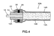
- the thickness of the membrane sheet 14 and embrocation 22 is normally several tens ⁇ m to several hundreds ⁇ m level, so that the new membrane sheet 14A, 14B have sufficient flexibility and elasticity. Therefore, as shown in Fig. 4 , when suction pressure from the inside or the pressing pressure from the outside is effected in the filtration of the water to be processed, the membrane sheets 14A, 14B sag to be closely attached to the water passing portion 12B of the support plate 12. Accordingly, the spaces g are actually not obstacles.
- an embrocation 30 having laser absorption property is applied further onto the surfaces of the respective new membrane sheets 14A, 14B, respectively, and when the durable years of the membrane sheets 14A, 14B is over, further replacement with new membranes is possible by the same regeneration method as above. According to the review result by the present inventor, when the regeneration as described above is repeated three to five times, no particular problem is caused in practice.
- the embrocation 22 having laser absorption property is applied on the surface of the membrane sheet 14 of the deposit fixed portion. Therefore, also in the regeneration of the flat membrane element 10, the deposit fixing of the membrane sheet by the laser emission can be performed in the same manner as in the new product manufacturing. Accordingly, the regeneration requires no additional facility, allowing the regeneration cost to be reduced. Further, the regenerated flat membrane element holds the same membrane area as of the new product, and its membrane sheet is deposit fixed by the same method as of the new product, causing no large difference in durability and reliability from the new product.
- Fig. 5 is a partial sectional side view showing a second embodiment of the flat membrane element according to the present invention.
- the elements denoted by the same numerical references as in Fig. 1 are the same elements as described in the first embodiment and therefore their detailed descriptions will be omitted here.
- an embrocation 22A is applied largely to cover the end portion of the membrane sheet 14, and the protective function to the deposit fixed portion 18 and the end of the membrane sheet 14 is enhanced by this embrocation 22A.
- Fig. 6 is a partial sectional side view showing a third embodiment of the flat membrane element according to the present invention.
- the elements denoted by the same numerical references as in Fig. 1 are the same elements as described in the first embodiment and therefore their detailed descriptions will be omitted here.
- the embrocation 22A is applied largely to cover the end portion of the membrane sheet 14 as in the second embodiment, and the state after the regenerations performed three times is shown in the drawing.
Landscapes
- Chemical & Material Sciences (AREA)
- Chemical Kinetics & Catalysis (AREA)
- Engineering & Computer Science (AREA)
- Manufacturing & Machinery (AREA)
- Physics & Mathematics (AREA)
- Plasma & Fusion (AREA)
- Inorganic Chemistry (AREA)
- Separation Using Semi-Permeable Membranes (AREA)
Description
- The present invention relates to a flat membrane element according to
claim 1. Further, the present invention relates to a regeneration method of a flat membrane element. - A flat membrane element of this kind is set in water to be processed in a dipped manner and used to filtrate the water to be processed.
Fig. 7 is a partial sectional view showing a general structure of a flat membrane element. Asupport plate 1 is formed such that acircumferential edge 2 thereof has a flame shape and awater passing portion 3 is formed in the inner portion thereof. Amembrane sheet 4 is attached onto both the faces of thesupport plate 1, respectively. Asuction port 5 is connected with thecircumferential edge 2. In addition, the outer surface of thecircumferential edge 2 and themembrane sheet 4 have ajoint portion 6 formed by lapping each other. By effecting negative pressure in thesuction port 5 or by effecting positive pressure from the outer surface of themembrane sheet 4, the water to be processed is filtrated and the filtrated water penetrated through themembrane sheet 4 is discharged from thesuction port 5 via thewater passing portion 3. Note that thewater passing portion 3 of thesupport plate 1 is specially treated to have a figure through which the filtrated water can pass freely while supporting the surface of themembrane sheet 4 to prevent the attachedmembrane sheet 4 from sagging. - The
membrane sheet 4 is called, for example, an ultrafiltration membrane or an ultrafilter membrane, and that made of synthetic resin is used in general. Also, as for thesupport plate 1, that made of synthetic resin, which shows a favorable joint characteristic with themembrane sheet 4, is used. It is important for the flat membrane element to ensure watertightness of thejoint portion 6, so that a method of jointing thesupport plate 1 and themembrane sheet 4 with an adhesive is widely employed. However, the method of using the adhesive easily causes deviation in adhesive force in addition to the problems that the adhesive deteriorates easily to lower the watertightness and that leak from the lateral direction of themembrane sheet 4 is easily caused. - As a method of improving the problem in the jointing method using the adhesive, a flat-membrane-element manufacturing method in which a membrane sheet is deposited on a support plate by lapping the membrane sheet and the support plate each other and emitting a laser to the mutually jointed portion is disclosed in
Japanese Patent Application Laid-Open No. 2005-279580 Japanese Patent Application Laid-Open No. 2005-279580 - The above-described flat membrane element causes an extreme clogging in the membrane sheet or the membrane sheet is damaged to be unable to hold a normal filtrating function when it filtrates the water to be processed for a long period of times. Although the spent flat membrane element over durable years as described above is normally processed or disposed as an industrial waste, it sometimes causes an environmental contamination when discarded. Further, in the flat membrane element, the material and processing costs of the support plate is overwhelmingly high as compared with the membrane sheet, and when the expensive support plate is thrown out as an industrial waste, the regeneration cost of the flat membrane element increases, posing a problem. Therefore, as a measure, it is conceivable that the membrane sheet over the durable years is pulled out and peeled from the support plate to reuse the support plate. However, the deposited portion of the membrane sheet and the support sheet which is deposited by the laser emission is rigid requiring many labor hours and costs to be pulled and peeled, being unadvisable.
- As a measure improving the problem as described above, in
Japanese Patent Application Laid-Open No. 2000-107576 - However, the regeneration method of the flat membrane element disclosed in
Japanese Patent Application Laid-Open No. 2000-107576 - An object of the present invention is to provide a flat membrane element capable of solving the above-described problems of the conventional art and at the same time prompting reuse of the support plate, while allowing the same method for fixing a membrane sheet for both cases where a new product is manufactured and where a spent product is regenerated, so that no difference is caused between the new product and the regenerated product in durability and reliability.
- A flat membrane element to solve the inventive object discloses the features of
independent claim 1. Accordingly, the flat membrane element performing solid-liquid separation, includes a membrane sheet for filtration, the membrane sheet being made of a synthetic resin material, a support plate to have the membrane sheet attached thereon; and a deposit fixed portion formed by a circumferential edge of the membrane sheet and the support sheet which are lapped each other and laser deposited; wherein an embrocation having laser absorption property applied on the surface of the membrane sheet of the deposit fixed portion to cover a laser deposited portion. The same synthetic resin material as of the membrane sheet added with a pigment is acceptable for the embrocation and the membrane sheet may be attached onto a single surface of the support plate or may be attached onto both the surfaces thereof. - Further, the object of the present invention is solved by a regeneration method of a flat membrane element. A membrane sheet is lapped onto a support plate to laser deposit a circumference of the membrane sheet, wherein the laser deposited portion is covered with an embrocation having laser absorption, wherein the membrane sheet inside the laser deposited portion is cut off and a new membrane sheet is lapped onto the embrocation and a laser deposition is performed thereto to regenerate the membrane element. It is preferable that the laser deposited portion of the newly lapped membrane sheet is covered by the embrocation with laser absorption property to prepare for a next regeneration.
- According to the flat membrane element and the regeneration method thereof, the embrocation having laser absorption property is applied on the surface of the membrane sheet of the deposit fixed portion. Therefore, even when regenerating the flat membrane element, the fixing of the membrane sheet by deposition with the laser emission can be performed as in the case of the new product manufacturing. Accordingly, the regeneration does not require any additional facility, so that the cost for the regeneration can be reduced. Further, the flat membrane element regenerated holds the same membrane area as of the new product, and its membrane sheet is fixed by deposition by the same method as of the new product, causing no difference in durability and reliability from the new product.
-
-
Fig. 1 is a partial sectional side view showing a first embodiment of a flat membrane element according to the present invention; -
Fig. 2 is a partial plan view showing the first embodiment of the flat membrane element according to the present invention; -
Figs. 3a to 3d are partial sectional side views showing regeneration procedures of aflat membrane element 10 in whichFig. 3a is a sectional view of a membrane sheet cutting off a solid-liquid separating area,Fig. 3b is a sectional view showing a state lapping a new membrane sheet,Fig. 3c is a sectional view showing a laser deposited state, andFig. 3d is a sectional view showing a state where the replacement with a new membrane sheet is performed with respect to an opposite surface; -
Fig. 4 is a partial sectional side view showing a state of a regeneratedflat membrane element 10A in use; -
Fig. 5 is a partial sectional side view showing a second embodiment of the flat membrane element; -
Fig. 6 is a partial sectional side view showing a third embodiment of the flat membrane element according to the present invention; and -
Fig. 7 is a partial sectional view showing a general structure of a flat membrane element. -
Fig. 1 is a partial sectional side view showing a first embodiment of a flat membrane element according to the present invention, andFig. 2 is a partial plan view thereof. Aflat membrane element 10 is structured to have amembrane sheet 14 attached onto each of both surfaces of asupport plate 12 as in conventional one. Asupport plate 12 is formed such that acircumferential edge 12A thereof has a flame shape and awater passing portion 12B is formed in the inner portion thereof. Asuction port 16 is connected with thecircumferential edge 12A. By effecting negative pressure in thesuction port 16 or by effecting positive pressure from the outer surface of themembrane sheet 14, the water to be processed is filtrated and the filtrated water permeated through themembrane sheet 14 is discharged from thesuction port 16 via thewater passing portion 12B. Note that thewater passing portion 12B of thesupport plate 12 is specially treated to have a figure through which the filtrated water can pass freely while supporting the surface of themembrane sheet 14 to prevent themembrane sheet 14 attached from sagging. - The
membrane sheet 14 is called for example an ultrafiltration membrane or an ultrafilter membrane, and that made of synthetic resin is used in general. Also, as for thesupport plate 12, that made of synthetic resin, which shows a favorable deposition characteristic with themembrane sheet 14, is used. The membrane sheet is made of a material having larger laser penetration and the support plate is made of a material having larger laser absorption property. By emitting a laser to a mutual joint portion of the circumferential edge of themembrane sheet 14 and thesupport plate 12, which are lapped, a deposit fixedportion 18 deposit fixing the circumferential edge portion of themembrane sheet 14 and thesupport plate 12 is formed. This deposit fixedportion 18 is firmly bonded and is hard to degrade, preventing a leak from the lateral direction along the joint surface of themembrane sheets 14. - An inside of the
membrane sheets 14 surrounded by the deposit fixedportion 18 is a solid-liquid separating area 20, and the filtrated water penetrated through the solid-liquid separating area 20 is discharged from thesuction port 16 via thewater passing portion 12B as described before. Anembrocation 22 having laser absorption property is applied on the surface of themembrane sheet 14 of the deposit fixedportion 18. As anembrocation 22, a synthetic resin material of the same type (for example, polyethylene, polyvinylidene fluoride, polyacrylonitrile or the like) as of the material of themembrane sheet 14 added with a pigment such as carbon black to improve the laser absorption property is preferably used. Theembrocation 22 serves also as a protective member blocking and protecting the deposit fixedportion 18 against an external environment. - The flat membrane element of the above-described structure causes an extreme clogging in the
membrane sheet 14 or themembrane sheet 14 is damaged to be unable to hold a normal filtrating function when it filtrate the water to be processed for a long period of times. The spentflat membrane element 10 over the durable years is regenerated by a method as will be described below.Figs. 3a to 3d are partial sectional side views showing regenerating procedures of theflat membrane element 10. First, in the first step (Fig. 3a ), of themembrane sheets 14 attached on both the surfaces of thesupport plate 12, portions corresponding to the solid-liquid separating area 20 shown inFig. 1 are cut off. As a result, as shown in the drawing, only the circumferential edge portion of themembrane sheet 14 remains in the state of deposite fixed with thesupport plate 12 and the deposit fixedportion 18. On the surface of the remainingmembrane sheet 14, theembrocation 22 remains as well. In the second step (Fig. 3b ), anew membrane sheet 14A is lapped on the remainingembrocation 22. In the third step (Fig. 3c ), alaser 24 is emitted from the upper surface of the lappednew membrane sheet 14A. Thelaser 24 penetrated through themembrane sheet 14A reaches theembrocation 22 to be absorbed thereby. Then, theembrocation 22 fuses first by heat of mixing. Subsequently, the fusion heat is conveyed to partially fuse the deposit fixedportion 18 on the lower side and themembrane sheet 14A on the upper side. After that, when the emission of thelaser 24 is removed, a new deposit fixedportion 26 formed by these fused substances cured in a unified manner is formed, and thenew membrane sheet 14A is firmly deposit fixed to thesupport plate 12. In the fourth step (Fig. 3d ), after themembrane sheet 14A is positioned on the under surface of thesupport plate 12 by reversing thesupport plate 1, and the second step (Fig. 3b ) and the third step (Fig. 3c ) are repeated also to thenew membrane sheet 14B on the other surface. By performing the above-described first to fourth steps, the regeneration of theflat membrane element 10 is completed. - In the regenerated
flat membrane element 10A, between thenew membrane sheets support plate 12, there are generated spaces g having the same thickness as of thenew membrane sheet 14 and theembrocation 22. However, the thickness of themembrane sheet 14 andembrocation 22 is normally several tens µ m to several hundreds µ m level, so that thenew membrane sheet Fig. 4 , when suction pressure from the inside or the pressing pressure from the outside is effected in the filtration of the water to be processed, themembrane sheets water passing portion 12B of thesupport plate 12. Accordingly, the spaces g are actually not obstacles. - Note that, as shown in
Fig. 4 , anembrocation 30 having laser absorption property is applied further onto the surfaces of the respectivenew membrane sheets membrane sheets - As described above, according to the
flat membrane element 10 and the regeneration method thereof, theembrocation 22 having laser absorption property is applied on the surface of themembrane sheet 14 of the deposit fixed portion. Therefore, also in the regeneration of theflat membrane element 10, the deposit fixing of the membrane sheet by the laser emission can be performed in the same manner as in the new product manufacturing. Accordingly, the regeneration requires no additional facility, allowing the regeneration cost to be reduced. Further, the regenerated flat membrane element holds the same membrane area as of the new product, and its membrane sheet is deposit fixed by the same method as of the new product, causing no large difference in durability and reliability from the new product. -
Fig. 5 is a partial sectional side view showing a second embodiment of the flat membrane element according to the present invention. InFig. 5 , the elements denoted by the same numerical references as inFig. 1 are the same elements as described in the first embodiment and therefore their detailed descriptions will be omitted here. In aflat membrane element 10B according to the present embodiment, anembrocation 22A is applied largely to cover the end portion of themembrane sheet 14, and the protective function to the deposit fixedportion 18 and the end of themembrane sheet 14 is enhanced by thisembrocation 22A. -
Fig. 6 is a partial sectional side view showing a third embodiment of the flat membrane element according to the present invention. InFig. 6 , the elements denoted by the same numerical references as inFig. 1 are the same elements as described in the first embodiment and therefore their detailed descriptions will be omitted here. In aflat membrane element 10C according to the present embodiment, theembrocation 22A is applied largely to cover the end portion of themembrane sheet 14 as in the second embodiment, and the state after the regenerations performed three times is shown in the drawing.
Claims (5)
- A flat membrane element (10) performing solid-liquid separation, comprising a membrane sheet (14) for filtration, the membrane sheet (14) being made of a synthetic resin material,
a support plate (12) to have said membrane sheet (14) attached thereon; and
a deposit fixed portion (18) formed by a circumferential edge (12A) of said membrane sheet (14) and said support plate (12) which are lapped each other and laser deposited,
characterized in that
an embrocation (22) having laser absorption property is applied on the surface of said membrane sheet (14) of said deposit fixed portion (18) to cover the laser deposited portion. - The flat membrane element (10) according to claim 1,
wherein said embrocation (22) is composed of a same synthetic resin material as of said membrane sheet (14) and a pigment mixed therein. - The flat membrane element (10) according to claim 1,
wherein said membrane sheet (14) is attached onto both surfaces of said support plate (12), respectively. - A regeneration method of a flat membrane element (10) lapping a membrane sheet (14) onto a support plate (12) to laser deposit a circumference of the membrane sheet (14),
characterized in that the laser deposited portion is covered with an embrocation (22) having laser absorption property,
wherein the membrane sheet (14) inside the laser deposited portion is cut off and a new membrane sheet (14A) is lapped onto the embrocation (22) and a laser deposition is performed thereto to regenerate the membrane element (10). - The regeneration method of the flat membrane element (10) according to claim 4,
wherein the laser deposited portion of the newly lapped membrane sheet (14A) is covered by the embrocation (22) having laser absorption property.
Applications Claiming Priority (1)
| Application Number | Priority Date | Filing Date | Title |
|---|---|---|---|
| JP2006001684A JP5019018B2 (en) | 2006-01-06 | 2006-01-06 | Flat membrane element and its regeneration method |
Publications (2)
| Publication Number | Publication Date |
|---|---|
| EP1806173A1 EP1806173A1 (en) | 2007-07-11 |
| EP1806173B1 true EP1806173B1 (en) | 2010-06-23 |
Family
ID=37775321
Family Applications (1)
| Application Number | Title | Priority Date | Filing Date |
|---|---|---|---|
| EP06026612A Not-in-force EP1806173B1 (en) | 2006-01-06 | 2006-12-21 | Flat membrane element and regeneration method thereof |
Country Status (6)
| Country | Link |
|---|---|
| US (2) | US7604130B2 (en) |
| EP (1) | EP1806173B1 (en) |
| JP (1) | JP5019018B2 (en) |
| KR (1) | KR101030938B1 (en) |
| CN (1) | CN101073749B (en) |
| DE (1) | DE602006015031D1 (en) |
Families Citing this family (2)
| Publication number | Priority date | Publication date | Assignee | Title |
|---|---|---|---|---|
| CN106178959B (en) * | 2016-08-11 | 2019-08-16 | 苏州艾吉克膜科技有限公司 | Recoverable membrane contactor and its recovery technique |
| CN113481505A (en) * | 2021-07-07 | 2021-10-08 | 南京科技职业学院 | Blind plate manufacturing method |
Family Cites Families (9)
| Publication number | Priority date | Publication date | Assignee | Title |
|---|---|---|---|---|
| JPS62142092A (en) | 1985-12-17 | 1987-06-25 | Honda Motor Co Ltd | How to bond parts using laser |
| KR0169205B1 (en) * | 1996-04-01 | 1999-01-15 | 노수홍 | Rotating plate attached to high concentration separation and condensation plate module at high pressure |
| US6103033A (en) | 1998-03-04 | 2000-08-15 | Therasense, Inc. | Process for producing an electrochemical biosensor |
| JP2000107576A (en) * | 1998-10-01 | 2000-04-18 | Kubota Corp | Regeneration method of membrane cartridge for activated sludge |
| JP3678594B2 (en) * | 1999-01-12 | 2005-08-03 | 株式会社クボタ | Membrane cartridge manufacturing method and recycling method |
| CN1314419C (en) * | 2002-08-15 | 2007-05-09 | 刘玉平 | Chinese medicine compound prescription for treating teeth and oral diseases |
| CN100531869C (en) * | 2004-03-30 | 2009-08-26 | 株式会社日立工业设备技术 | Flat membrane elements and support plates |
| JP4412472B2 (en) | 2004-03-30 | 2010-02-10 | 株式会社日立プラントテクノロジー | Manufacturing method of flat membrane element |
| JP2005279579A (en) * | 2004-03-30 | 2005-10-13 | Hitachi Plant Eng & Constr Co Ltd | Manufacturing method of flat membrane element |
-
2006
- 2006-01-06 JP JP2006001684A patent/JP5019018B2/en not_active Expired - Fee Related
- 2006-12-18 US US11/640,314 patent/US7604130B2/en not_active Expired - Fee Related
- 2006-12-21 EP EP06026612A patent/EP1806173B1/en not_active Not-in-force
- 2006-12-21 DE DE602006015031T patent/DE602006015031D1/en active Active
-
2007
- 2007-01-05 KR KR1020070001306A patent/KR101030938B1/en not_active Expired - Fee Related
- 2007-01-08 CN CN2007100923350A patent/CN101073749B/en not_active Expired - Fee Related
-
2009
- 2009-03-20 US US12/382,654 patent/US7992724B2/en not_active Expired - Fee Related
Also Published As
| Publication number | Publication date |
|---|---|
| CN101073749A (en) | 2007-11-21 |
| EP1806173A1 (en) | 2007-07-11 |
| KR20070074479A (en) | 2007-07-12 |
| US7604130B2 (en) | 2009-10-20 |
| DE602006015031D1 (en) | 2010-08-05 |
| KR101030938B1 (en) | 2011-04-28 |
| CN101073749B (en) | 2011-11-23 |
| JP5019018B2 (en) | 2012-09-05 |
| US20090202746A1 (en) | 2009-08-13 |
| JP2007181780A (en) | 2007-07-19 |
| US7992724B2 (en) | 2011-08-09 |
| US20070158254A1 (en) | 2007-07-12 |
Similar Documents
| Publication | Publication Date | Title |
|---|---|---|
| US8414767B2 (en) | Module for purifying a fluid, in particular water | |
| EP0327394B1 (en) | Cell-type filter cartridge | |
| EP1366804B1 (en) | Method of replacement of a filtration membrane of a filtration cartridge for activated sludge | |
| JP2008238167A (en) | Cassette type filtration apparatus | |
| EP1570896A1 (en) | A hollow fiber membrane contactor and method of making same | |
| US4871456A (en) | Stacked filter cartridge with porous filter support | |
| US7992724B2 (en) | Flat membrane element and regeneration method thereof | |
| CN113164875A (en) | Disposable sterile tangential flow filtration systems and methods | |
| CN102325582B (en) | Edge member for film element and film element equipped with same | |
| CN108367247A (en) | Membrane component and membrane component end member for it | |
| US6352641B1 (en) | Wound pocket module | |
| JP2005230814A (en) | Method for producing hollow fiber membrane module | |
| JP6098098B2 (en) | Membrane module, membrane unit | |
| JP2012183464A (en) | Telescope prevention plate for fluid separation element, and fluid separation element | |
| EP1806172B1 (en) | Flat membrane element and manufacturing method thereof | |
| JP2006218345A (en) | Spiral type membrane element and manufacturing method thereof | |
| US20240139656A1 (en) | Sanitary membrane leaf packet and membrane element including same | |
| JP4485410B2 (en) | Spiral type separation membrane element and manufacturing method thereof | |
| JPS6372305A (en) | Bonding method for filter membrane of filter cartridge | |
| JP2005211790A (en) | Spiral type membrane element and backflow cleaning method thereof | |
| JP2006136839A (en) | Spiral membrane element | |
| JP3128588U (en) | Filter cartridge | |
| JPS6344909A (en) | Filter cartridge | |
| JP4331629B2 (en) | Cartridge filter for microfiltration | |
| JP4222243B2 (en) | Spiral membrane element |
Legal Events
| Date | Code | Title | Description |
|---|---|---|---|
| PUAI | Public reference made under article 153(3) epc to a published international application that has entered the european phase |
Free format text: ORIGINAL CODE: 0009012 |
|
| AK | Designated contracting states |
Kind code of ref document: A1 Designated state(s): AT BE BG CH CY CZ DE DK EE ES FI FR GB GR HU IE IS IT LI LT LU LV MC NL PL PT RO SE SI SK TR |
|
| AX | Request for extension of the european patent |
Extension state: AL BA HR MK YU |
|
| RAP1 | Party data changed (applicant data changed or rights of an application transferred) |
Owner name: HITACHI PLANT TECHNOLOGIES, LTD. |
|
| 17P | Request for examination filed |
Effective date: 20070905 |
|
| 17Q | First examination report despatched |
Effective date: 20071008 |
|
| AKX | Designation fees paid |
Designated state(s): DE FR GB NL |
|
| GRAP | Despatch of communication of intention to grant a patent |
Free format text: ORIGINAL CODE: EPIDOSNIGR1 |
|
| GRAS | Grant fee paid |
Free format text: ORIGINAL CODE: EPIDOSNIGR3 |
|
| GRAA | (expected) grant |
Free format text: ORIGINAL CODE: 0009210 |
|
| AK | Designated contracting states |
Kind code of ref document: B1 Designated state(s): DE FR GB NL |
|
| REF | Corresponds to: |
Ref document number: 602006015031 Country of ref document: DE Date of ref document: 20100805 Kind code of ref document: P |
|
| REG | Reference to a national code |
Ref country code: NL Ref legal event code: T3 |
|
| PLBE | No opposition filed within time limit |
Free format text: ORIGINAL CODE: 0009261 |
|
| STAA | Information on the status of an ep patent application or granted ep patent |
Free format text: STATUS: NO OPPOSITION FILED WITHIN TIME LIMIT |
|
| 26N | No opposition filed |
Effective date: 20110324 |
|
| REG | Reference to a national code |
Ref country code: DE Ref legal event code: R097 Ref document number: 602006015031 Country of ref document: DE Effective date: 20110323 |
|
| REG | Reference to a national code |
Ref country code: DE Ref legal event code: R082 Ref document number: 602006015031 Country of ref document: DE Representative=s name: GRUENECKER, KINKELDEY, STOCKMAIR & SCHWANHAEUS, DE |
|
| REG | Reference to a national code |
Ref country code: NL Ref legal event code: SD Effective date: 20140226 |
|
| REG | Reference to a national code |
Ref country code: GB Ref legal event code: 732E Free format text: REGISTERED BETWEEN 20140220 AND 20140226 |
|
| REG | Reference to a national code |
Ref country code: DE Ref legal event code: R082 Ref document number: 602006015031 Country of ref document: DE Representative=s name: GRUENECKER, KINKELDEY, STOCKMAIR & SCHWANHAEUS, DE Effective date: 20140218 Ref country code: DE Ref legal event code: R081 Ref document number: 602006015031 Country of ref document: DE Owner name: HITACHI, LTD., JP Free format text: FORMER OWNER: HITACHI PLANT TECHNOLOGIES, LTD., TOKIO, JP Effective date: 20140218 Ref country code: DE Ref legal event code: R082 Ref document number: 602006015031 Country of ref document: DE Representative=s name: GRUENECKER PATENT- UND RECHTSANWAELTE PARTG MB, DE Effective date: 20140218 |
|
| REG | Reference to a national code |
Ref country code: FR Ref legal event code: TP Owner name: HITACHI PLANT TECHNOLOGIES, LTD., JP Effective date: 20140612 |
|
| PGFP | Annual fee paid to national office [announced via postgrant information from national office to epo] |
Ref country code: GB Payment date: 20141218 Year of fee payment: 9 |
|
| PGFP | Annual fee paid to national office [announced via postgrant information from national office to epo] |
Ref country code: NL Payment date: 20141218 Year of fee payment: 9 Ref country code: FR Payment date: 20141218 Year of fee payment: 9 |
|
| PGFP | Annual fee paid to national office [announced via postgrant information from national office to epo] |
Ref country code: DE Payment date: 20141223 Year of fee payment: 9 |
|
| REG | Reference to a national code |
Ref country code: DE Ref legal event code: R119 Ref document number: 602006015031 Country of ref document: DE |
|
| GBPC | Gb: european patent ceased through non-payment of renewal fee |
Effective date: 20151221 |
|
| REG | Reference to a national code |
Ref country code: NL Ref legal event code: MM Effective date: 20160101 |
|
| REG | Reference to a national code |
Ref country code: FR Ref legal event code: ST Effective date: 20160831 |
|
| PG25 | Lapsed in a contracting state [announced via postgrant information from national office to epo] |
Ref country code: DE Free format text: LAPSE BECAUSE OF NON-PAYMENT OF DUE FEES Effective date: 20160701 Ref country code: GB Free format text: LAPSE BECAUSE OF NON-PAYMENT OF DUE FEES Effective date: 20151221 Ref country code: NL Free format text: LAPSE BECAUSE OF NON-PAYMENT OF DUE FEES Effective date: 20160101 |
|
| PG25 | Lapsed in a contracting state [announced via postgrant information from national office to epo] |
Ref country code: FR Free format text: LAPSE BECAUSE OF NON-PAYMENT OF DUE FEES Effective date: 20151231 |