EP1805451B1 - Liquefying and storing a gas - Google Patents
Liquefying and storing a gas Download PDFInfo
- Publication number
- EP1805451B1 EP1805451B1 EP05824289.2A EP05824289A EP1805451B1 EP 1805451 B1 EP1805451 B1 EP 1805451B1 EP 05824289 A EP05824289 A EP 05824289A EP 1805451 B1 EP1805451 B1 EP 1805451B1
- Authority
- EP
- European Patent Office
- Prior art keywords
- dewar
- valve
- oxygen
- gas
- cryocooler
- Prior art date
- Legal status (The legal status is an assumption and is not a legal conclusion. Google has not performed a legal analysis and makes no representation as to the accuracy of the status listed.)
- Expired - Lifetime
Links
Images













Classifications
-
- F—MECHANICAL ENGINEERING; LIGHTING; HEATING; WEAPONS; BLASTING
- F17—STORING OR DISTRIBUTING GASES OR LIQUIDS
- F17C—VESSELS FOR CONTAINING OR STORING COMPRESSED, LIQUEFIED OR SOLIDIFIED GASES; FIXED-CAPACITY GAS-HOLDERS; FILLING VESSELS WITH, OR DISCHARGING FROM VESSELS, COMPRESSED, LIQUEFIED, OR SOLIDIFIED GASES
- F17C9/00—Methods or apparatus for discharging liquefied or solidified gases from vessels not under pressure
-
- F—MECHANICAL ENGINEERING; LIGHTING; HEATING; WEAPONS; BLASTING
- F17—STORING OR DISTRIBUTING GASES OR LIQUIDS
- F17C—VESSELS FOR CONTAINING OR STORING COMPRESSED, LIQUEFIED OR SOLIDIFIED GASES; FIXED-CAPACITY GAS-HOLDERS; FILLING VESSELS WITH, OR DISCHARGING FROM VESSELS, COMPRESSED, LIQUEFIED, OR SOLIDIFIED GASES
- F17C3/00—Vessels not under pressure
- F17C3/02—Vessels not under pressure with provision for thermal insulation
- F17C3/08—Vessels not under pressure with provision for thermal insulation by vacuum spaces, e.g. Dewar flask
- F17C3/085—Cryostats
-
- F—MECHANICAL ENGINEERING; LIGHTING; HEATING; WEAPONS; BLASTING
- F25—REFRIGERATION OR COOLING; COMBINED HEATING AND REFRIGERATION SYSTEMS; HEAT PUMP SYSTEMS; MANUFACTURE OR STORAGE OF ICE; LIQUEFACTION SOLIDIFICATION OF GASES
- F25J—LIQUEFACTION, SOLIDIFICATION OR SEPARATION OF GASES OR GASEOUS OR LIQUEFIED GASEOUS MIXTURES BY PRESSURE AND COLD TREATMENT OR BY BRINGING THEM INTO THE SUPERCRITICAL STATE
- F25J1/00—Processes or apparatus for liquefying or solidifying gases or gaseous mixtures
- F25J1/0002—Processes or apparatus for liquefying or solidifying gases or gaseous mixtures characterised by the fluid to be liquefied
- F25J1/0012—Primary atmospheric gases, e.g. air
- F25J1/0017—Oxygen
-
- F—MECHANICAL ENGINEERING; LIGHTING; HEATING; WEAPONS; BLASTING
- F25—REFRIGERATION OR COOLING; COMBINED HEATING AND REFRIGERATION SYSTEMS; HEAT PUMP SYSTEMS; MANUFACTURE OR STORAGE OF ICE; LIQUEFACTION SOLIDIFICATION OF GASES
- F25J—LIQUEFACTION, SOLIDIFICATION OR SEPARATION OF GASES OR GASEOUS OR LIQUEFIED GASEOUS MIXTURES BY PRESSURE AND COLD TREATMENT OR BY BRINGING THEM INTO THE SUPERCRITICAL STATE
- F25J1/00—Processes or apparatus for liquefying or solidifying gases or gaseous mixtures
- F25J1/02—Processes or apparatus for liquefying or solidifying gases or gaseous mixtures requiring the use of refrigeration, e.g. of helium or hydrogen ; Details and kind of the refrigeration system used; Integration with other units or processes; Controlling aspects of the process
- F25J1/0225—Processes or apparatus for liquefying or solidifying gases or gaseous mixtures requiring the use of refrigeration, e.g. of helium or hydrogen ; Details and kind of the refrigeration system used; Integration with other units or processes; Controlling aspects of the process using other external refrigeration means not provided before, e.g. heat driven absorption chillers
-
- A—HUMAN NECESSITIES
- A61—MEDICAL OR VETERINARY SCIENCE; HYGIENE
- A61M—DEVICES FOR INTRODUCING MEDIA INTO, OR ONTO, THE BODY; DEVICES FOR TRANSDUCING BODY MEDIA OR FOR TAKING MEDIA FROM THE BODY; DEVICES FOR PRODUCING OR ENDING SLEEP OR STUPOR
- A61M16/00—Devices for influencing the respiratory system of patients by gas treatment, e.g. ventilators; Tracheal tubes
- A61M16/10—Preparation of respiratory gases or vapours
-
- A—HUMAN NECESSITIES
- A61—MEDICAL OR VETERINARY SCIENCE; HYGIENE
- A61M—DEVICES FOR INTRODUCING MEDIA INTO, OR ONTO, THE BODY; DEVICES FOR TRANSDUCING BODY MEDIA OR FOR TAKING MEDIA FROM THE BODY; DEVICES FOR PRODUCING OR ENDING SLEEP OR STUPOR
- A61M16/00—Devices for influencing the respiratory system of patients by gas treatment, e.g. ventilators; Tracheal tubes
- A61M16/10—Preparation of respiratory gases or vapours
- A61M16/1005—Preparation of respiratory gases or vapours with O2 features or with parameter measurement
- A61M16/101—Preparation of respiratory gases or vapours with O2 features or with parameter measurement using an oxygen concentrator
-
- A—HUMAN NECESSITIES
- A61—MEDICAL OR VETERINARY SCIENCE; HYGIENE
- A61M—DEVICES FOR INTRODUCING MEDIA INTO, OR ONTO, THE BODY; DEVICES FOR TRANSDUCING BODY MEDIA OR FOR TAKING MEDIA FROM THE BODY; DEVICES FOR PRODUCING OR ENDING SLEEP OR STUPOR
- A61M2202/00—Special media to be introduced, removed or treated
- A61M2202/02—Gases
- A61M2202/0208—Oxygen
-
- A—HUMAN NECESSITIES
- A61—MEDICAL OR VETERINARY SCIENCE; HYGIENE
- A61M—DEVICES FOR INTRODUCING MEDIA INTO, OR ONTO, THE BODY; DEVICES FOR TRANSDUCING BODY MEDIA OR FOR TAKING MEDIA FROM THE BODY; DEVICES FOR PRODUCING OR ENDING SLEEP OR STUPOR
- A61M2202/00—Special media to be introduced, removed or treated
- A61M2202/03—Gases in liquid phase, e.g. cryogenic liquids
-
- A—HUMAN NECESSITIES
- A61—MEDICAL OR VETERINARY SCIENCE; HYGIENE
- A61M—DEVICES FOR INTRODUCING MEDIA INTO, OR ONTO, THE BODY; DEVICES FOR TRANSDUCING BODY MEDIA OR FOR TAKING MEDIA FROM THE BODY; DEVICES FOR PRODUCING OR ENDING SLEEP OR STUPOR
- A61M2205/00—General characteristics of the apparatus
- A61M2205/33—Controlling, regulating or measuring
- A61M2205/3317—Electromagnetic, inductive or dielectric measuring means
-
- A—HUMAN NECESSITIES
- A61—MEDICAL OR VETERINARY SCIENCE; HYGIENE
- A61M—DEVICES FOR INTRODUCING MEDIA INTO, OR ONTO, THE BODY; DEVICES FOR TRANSDUCING BODY MEDIA OR FOR TAKING MEDIA FROM THE BODY; DEVICES FOR PRODUCING OR ENDING SLEEP OR STUPOR
- A61M2205/00—General characteristics of the apparatus
- A61M2205/33—Controlling, regulating or measuring
- A61M2205/3379—Masses, volumes, levels of fluids in reservoirs, flow rates
- A61M2205/3389—Continuous level detection
-
- F—MECHANICAL ENGINEERING; LIGHTING; HEATING; WEAPONS; BLASTING
- F17—STORING OR DISTRIBUTING GASES OR LIQUIDS
- F17C—VESSELS FOR CONTAINING OR STORING COMPRESSED, LIQUEFIED OR SOLIDIFIED GASES; FIXED-CAPACITY GAS-HOLDERS; FILLING VESSELS WITH, OR DISCHARGING FROM VESSELS, COMPRESSED, LIQUEFIED, OR SOLIDIFIED GASES
- F17C2201/00—Vessel construction, in particular geometry, arrangement or size
- F17C2201/01—Shape
- F17C2201/0104—Shape cylindrical
-
- F—MECHANICAL ENGINEERING; LIGHTING; HEATING; WEAPONS; BLASTING
- F17—STORING OR DISTRIBUTING GASES OR LIQUIDS
- F17C—VESSELS FOR CONTAINING OR STORING COMPRESSED, LIQUEFIED OR SOLIDIFIED GASES; FIXED-CAPACITY GAS-HOLDERS; FILLING VESSELS WITH, OR DISCHARGING FROM VESSELS, COMPRESSED, LIQUEFIED, OR SOLIDIFIED GASES
- F17C2201/00—Vessel construction, in particular geometry, arrangement or size
- F17C2201/03—Orientation
- F17C2201/032—Orientation with substantially vertical main axis
-
- F—MECHANICAL ENGINEERING; LIGHTING; HEATING; WEAPONS; BLASTING
- F17—STORING OR DISTRIBUTING GASES OR LIQUIDS
- F17C—VESSELS FOR CONTAINING OR STORING COMPRESSED, LIQUEFIED OR SOLIDIFIED GASES; FIXED-CAPACITY GAS-HOLDERS; FILLING VESSELS WITH, OR DISCHARGING FROM VESSELS, COMPRESSED, LIQUEFIED, OR SOLIDIFIED GASES
- F17C2201/00—Vessel construction, in particular geometry, arrangement or size
- F17C2201/05—Size
- F17C2201/056—Small (<1 m3)
-
- F—MECHANICAL ENGINEERING; LIGHTING; HEATING; WEAPONS; BLASTING
- F17—STORING OR DISTRIBUTING GASES OR LIQUIDS
- F17C—VESSELS FOR CONTAINING OR STORING COMPRESSED, LIQUEFIED OR SOLIDIFIED GASES; FIXED-CAPACITY GAS-HOLDERS; FILLING VESSELS WITH, OR DISCHARGING FROM VESSELS, COMPRESSED, LIQUEFIED, OR SOLIDIFIED GASES
- F17C2203/00—Vessel construction, in particular walls or details thereof
- F17C2203/01—Reinforcing or suspension means
- F17C2203/014—Suspension means
- F17C2203/018—Suspension means by attachment at the neck
-
- F—MECHANICAL ENGINEERING; LIGHTING; HEATING; WEAPONS; BLASTING
- F17—STORING OR DISTRIBUTING GASES OR LIQUIDS
- F17C—VESSELS FOR CONTAINING OR STORING COMPRESSED, LIQUEFIED OR SOLIDIFIED GASES; FIXED-CAPACITY GAS-HOLDERS; FILLING VESSELS WITH, OR DISCHARGING FROM VESSELS, COMPRESSED, LIQUEFIED, OR SOLIDIFIED GASES
- F17C2203/00—Vessel construction, in particular walls or details thereof
- F17C2203/03—Thermal insulations
- F17C2203/0304—Thermal insulations by solid means
- F17C2203/0308—Radiation shield
-
- F—MECHANICAL ENGINEERING; LIGHTING; HEATING; WEAPONS; BLASTING
- F17—STORING OR DISTRIBUTING GASES OR LIQUIDS
- F17C—VESSELS FOR CONTAINING OR STORING COMPRESSED, LIQUEFIED OR SOLIDIFIED GASES; FIXED-CAPACITY GAS-HOLDERS; FILLING VESSELS WITH, OR DISCHARGING FROM VESSELS, COMPRESSED, LIQUEFIED, OR SOLIDIFIED GASES
- F17C2203/00—Vessel construction, in particular walls or details thereof
- F17C2203/03—Thermal insulations
- F17C2203/0391—Thermal insulations by vacuum
- F17C2203/0395—Getter
-
- F—MECHANICAL ENGINEERING; LIGHTING; HEATING; WEAPONS; BLASTING
- F17—STORING OR DISTRIBUTING GASES OR LIQUIDS
- F17C—VESSELS FOR CONTAINING OR STORING COMPRESSED, LIQUEFIED OR SOLIDIFIED GASES; FIXED-CAPACITY GAS-HOLDERS; FILLING VESSELS WITH, OR DISCHARGING FROM VESSELS, COMPRESSED, LIQUEFIED, OR SOLIDIFIED GASES
- F17C2203/00—Vessel construction, in particular walls or details thereof
- F17C2203/06—Materials for walls or layers thereof; Properties or structures of walls or their materials
- F17C2203/0634—Materials for walls or layers thereof
- F17C2203/0636—Metals
- F17C2203/0639—Steels
- F17C2203/0643—Stainless steels
-
- F—MECHANICAL ENGINEERING; LIGHTING; HEATING; WEAPONS; BLASTING
- F17—STORING OR DISTRIBUTING GASES OR LIQUIDS
- F17C—VESSELS FOR CONTAINING OR STORING COMPRESSED, LIQUEFIED OR SOLIDIFIED GASES; FIXED-CAPACITY GAS-HOLDERS; FILLING VESSELS WITH, OR DISCHARGING FROM VESSELS, COMPRESSED, LIQUEFIED, OR SOLIDIFIED GASES
- F17C2205/00—Vessel construction, in particular mounting arrangements, attachments or identifications means
- F17C2205/01—Mounting arrangements
- F17C2205/0153—Details of mounting arrangements
- F17C2205/0157—Details of mounting arrangements for transport
-
- F—MECHANICAL ENGINEERING; LIGHTING; HEATING; WEAPONS; BLASTING
- F17—STORING OR DISTRIBUTING GASES OR LIQUIDS
- F17C—VESSELS FOR CONTAINING OR STORING COMPRESSED, LIQUEFIED OR SOLIDIFIED GASES; FIXED-CAPACITY GAS-HOLDERS; FILLING VESSELS WITH, OR DISCHARGING FROM VESSELS, COMPRESSED, LIQUEFIED, OR SOLIDIFIED GASES
- F17C2205/00—Vessel construction, in particular mounting arrangements, attachments or identifications means
- F17C2205/03—Fluid connections, filters, valves, closure means or other attachments
- F17C2205/0302—Fittings, valves, filters, or components in connection with the gas storage device
- F17C2205/0323—Valves
- F17C2205/0326—Valves electrically actuated
-
- F—MECHANICAL ENGINEERING; LIGHTING; HEATING; WEAPONS; BLASTING
- F17—STORING OR DISTRIBUTING GASES OR LIQUIDS
- F17C—VESSELS FOR CONTAINING OR STORING COMPRESSED, LIQUEFIED OR SOLIDIFIED GASES; FIXED-CAPACITY GAS-HOLDERS; FILLING VESSELS WITH, OR DISCHARGING FROM VESSELS, COMPRESSED, LIQUEFIED, OR SOLIDIFIED GASES
- F17C2205/00—Vessel construction, in particular mounting arrangements, attachments or identifications means
- F17C2205/03—Fluid connections, filters, valves, closure means or other attachments
- F17C2205/0302—Fittings, valves, filters, or components in connection with the gas storage device
- F17C2205/0323—Valves
- F17C2205/0332—Safety valves or pressure relief valves
-
- F—MECHANICAL ENGINEERING; LIGHTING; HEATING; WEAPONS; BLASTING
- F17—STORING OR DISTRIBUTING GASES OR LIQUIDS
- F17C—VESSELS FOR CONTAINING OR STORING COMPRESSED, LIQUEFIED OR SOLIDIFIED GASES; FIXED-CAPACITY GAS-HOLDERS; FILLING VESSELS WITH, OR DISCHARGING FROM VESSELS, COMPRESSED, LIQUEFIED, OR SOLIDIFIED GASES
- F17C2205/00—Vessel construction, in particular mounting arrangements, attachments or identifications means
- F17C2205/03—Fluid connections, filters, valves, closure means or other attachments
- F17C2205/0302—Fittings, valves, filters, or components in connection with the gas storage device
- F17C2205/0323—Valves
- F17C2205/0335—Check-valves or non-return valves
-
- F—MECHANICAL ENGINEERING; LIGHTING; HEATING; WEAPONS; BLASTING
- F17—STORING OR DISTRIBUTING GASES OR LIQUIDS
- F17C—VESSELS FOR CONTAINING OR STORING COMPRESSED, LIQUEFIED OR SOLIDIFIED GASES; FIXED-CAPACITY GAS-HOLDERS; FILLING VESSELS WITH, OR DISCHARGING FROM VESSELS, COMPRESSED, LIQUEFIED, OR SOLIDIFIED GASES
- F17C2205/00—Vessel construction, in particular mounting arrangements, attachments or identifications means
- F17C2205/03—Fluid connections, filters, valves, closure means or other attachments
- F17C2205/0302—Fittings, valves, filters, or components in connection with the gas storage device
- F17C2205/0352—Pipes
-
- F—MECHANICAL ENGINEERING; LIGHTING; HEATING; WEAPONS; BLASTING
- F17—STORING OR DISTRIBUTING GASES OR LIQUIDS
- F17C—VESSELS FOR CONTAINING OR STORING COMPRESSED, LIQUEFIED OR SOLIDIFIED GASES; FIXED-CAPACITY GAS-HOLDERS; FILLING VESSELS WITH, OR DISCHARGING FROM VESSELS, COMPRESSED, LIQUEFIED, OR SOLIDIFIED GASES
- F17C2221/00—Handled fluid, in particular type of fluid
- F17C2221/01—Pure fluids
- F17C2221/011—Oxygen
-
- F—MECHANICAL ENGINEERING; LIGHTING; HEATING; WEAPONS; BLASTING
- F17—STORING OR DISTRIBUTING GASES OR LIQUIDS
- F17C—VESSELS FOR CONTAINING OR STORING COMPRESSED, LIQUEFIED OR SOLIDIFIED GASES; FIXED-CAPACITY GAS-HOLDERS; FILLING VESSELS WITH, OR DISCHARGING FROM VESSELS, COMPRESSED, LIQUEFIED, OR SOLIDIFIED GASES
- F17C2221/00—Handled fluid, in particular type of fluid
- F17C2221/01—Pure fluids
- F17C2221/014—Nitrogen
-
- F—MECHANICAL ENGINEERING; LIGHTING; HEATING; WEAPONS; BLASTING
- F17—STORING OR DISTRIBUTING GASES OR LIQUIDS
- F17C—VESSELS FOR CONTAINING OR STORING COMPRESSED, LIQUEFIED OR SOLIDIFIED GASES; FIXED-CAPACITY GAS-HOLDERS; FILLING VESSELS WITH, OR DISCHARGING FROM VESSELS, COMPRESSED, LIQUEFIED, OR SOLIDIFIED GASES
- F17C2221/00—Handled fluid, in particular type of fluid
- F17C2221/01—Pure fluids
- F17C2221/016—Noble gases (Ar, Kr, Xe)
-
- F—MECHANICAL ENGINEERING; LIGHTING; HEATING; WEAPONS; BLASTING
- F17—STORING OR DISTRIBUTING GASES OR LIQUIDS
- F17C—VESSELS FOR CONTAINING OR STORING COMPRESSED, LIQUEFIED OR SOLIDIFIED GASES; FIXED-CAPACITY GAS-HOLDERS; FILLING VESSELS WITH, OR DISCHARGING FROM VESSELS, COMPRESSED, LIQUEFIED, OR SOLIDIFIED GASES
- F17C2221/00—Handled fluid, in particular type of fluid
- F17C2221/03—Mixtures
- F17C2221/031—Air
-
- F—MECHANICAL ENGINEERING; LIGHTING; HEATING; WEAPONS; BLASTING
- F17—STORING OR DISTRIBUTING GASES OR LIQUIDS
- F17C—VESSELS FOR CONTAINING OR STORING COMPRESSED, LIQUEFIED OR SOLIDIFIED GASES; FIXED-CAPACITY GAS-HOLDERS; FILLING VESSELS WITH, OR DISCHARGING FROM VESSELS, COMPRESSED, LIQUEFIED, OR SOLIDIFIED GASES
- F17C2223/00—Handled fluid before transfer, i.e. state of fluid when stored in the vessel or before transfer from the vessel
- F17C2223/01—Handled fluid before transfer, i.e. state of fluid when stored in the vessel or before transfer from the vessel characterised by the phase
- F17C2223/0146—Two-phase
- F17C2223/0153—Liquefied gas, e.g. LPG, GPL
- F17C2223/0161—Liquefied gas, e.g. LPG, GPL cryogenic, e.g. LNG, GNL, PLNG
-
- F—MECHANICAL ENGINEERING; LIGHTING; HEATING; WEAPONS; BLASTING
- F17—STORING OR DISTRIBUTING GASES OR LIQUIDS
- F17C—VESSELS FOR CONTAINING OR STORING COMPRESSED, LIQUEFIED OR SOLIDIFIED GASES; FIXED-CAPACITY GAS-HOLDERS; FILLING VESSELS WITH, OR DISCHARGING FROM VESSELS, COMPRESSED, LIQUEFIED, OR SOLIDIFIED GASES
- F17C2223/00—Handled fluid before transfer, i.e. state of fluid when stored in the vessel or before transfer from the vessel
- F17C2223/03—Handled fluid before transfer, i.e. state of fluid when stored in the vessel or before transfer from the vessel characterised by the pressure level
- F17C2223/033—Small pressure, e.g. for liquefied gas
-
- F—MECHANICAL ENGINEERING; LIGHTING; HEATING; WEAPONS; BLASTING
- F17—STORING OR DISTRIBUTING GASES OR LIQUIDS
- F17C—VESSELS FOR CONTAINING OR STORING COMPRESSED, LIQUEFIED OR SOLIDIFIED GASES; FIXED-CAPACITY GAS-HOLDERS; FILLING VESSELS WITH, OR DISCHARGING FROM VESSELS, COMPRESSED, LIQUEFIED, OR SOLIDIFIED GASES
- F17C2223/00—Handled fluid before transfer, i.e. state of fluid when stored in the vessel or before transfer from the vessel
- F17C2223/04—Handled fluid before transfer, i.e. state of fluid when stored in the vessel or before transfer from the vessel characterised by other properties of handled fluid before transfer
- F17C2223/042—Localisation of the removal point
- F17C2223/046—Localisation of the removal point in the liquid
- F17C2223/047—Localisation of the removal point in the liquid with a dip tube
-
- F—MECHANICAL ENGINEERING; LIGHTING; HEATING; WEAPONS; BLASTING
- F17—STORING OR DISTRIBUTING GASES OR LIQUIDS
- F17C—VESSELS FOR CONTAINING OR STORING COMPRESSED, LIQUEFIED OR SOLIDIFIED GASES; FIXED-CAPACITY GAS-HOLDERS; FILLING VESSELS WITH, OR DISCHARGING FROM VESSELS, COMPRESSED, LIQUEFIED, OR SOLIDIFIED GASES
- F17C2225/00—Handled fluid after transfer, i.e. state of fluid after transfer from the vessel
- F17C2225/01—Handled fluid after transfer, i.e. state of fluid after transfer from the vessel characterised by the phase
- F17C2225/0146—Two-phase
- F17C2225/0153—Liquefied gas, e.g. LPG, GPL
- F17C2225/0161—Liquefied gas, e.g. LPG, GPL cryogenic, e.g. LNG, GNL, PLNG
-
- F—MECHANICAL ENGINEERING; LIGHTING; HEATING; WEAPONS; BLASTING
- F17—STORING OR DISTRIBUTING GASES OR LIQUIDS
- F17C—VESSELS FOR CONTAINING OR STORING COMPRESSED, LIQUEFIED OR SOLIDIFIED GASES; FIXED-CAPACITY GAS-HOLDERS; FILLING VESSELS WITH, OR DISCHARGING FROM VESSELS, COMPRESSED, LIQUEFIED, OR SOLIDIFIED GASES
- F17C2227/00—Transfer of fluids, i.e. method or means for transferring the fluid; Heat exchange with the fluid
- F17C2227/01—Propulsion of the fluid
- F17C2227/0107—Propulsion of the fluid by pressurising the ullage
-
- F—MECHANICAL ENGINEERING; LIGHTING; HEATING; WEAPONS; BLASTING
- F17—STORING OR DISTRIBUTING GASES OR LIQUIDS
- F17C—VESSELS FOR CONTAINING OR STORING COMPRESSED, LIQUEFIED OR SOLIDIFIED GASES; FIXED-CAPACITY GAS-HOLDERS; FILLING VESSELS WITH, OR DISCHARGING FROM VESSELS, COMPRESSED, LIQUEFIED, OR SOLIDIFIED GASES
- F17C2227/00—Transfer of fluids, i.e. method or means for transferring the fluid; Heat exchange with the fluid
- F17C2227/01—Propulsion of the fluid
- F17C2227/0128—Propulsion of the fluid with pumps or compressors
- F17C2227/0157—Compressors
-
- F—MECHANICAL ENGINEERING; LIGHTING; HEATING; WEAPONS; BLASTING
- F17—STORING OR DISTRIBUTING GASES OR LIQUIDS
- F17C—VESSELS FOR CONTAINING OR STORING COMPRESSED, LIQUEFIED OR SOLIDIFIED GASES; FIXED-CAPACITY GAS-HOLDERS; FILLING VESSELS WITH, OR DISCHARGING FROM VESSELS, COMPRESSED, LIQUEFIED, OR SOLIDIFIED GASES
- F17C2227/00—Transfer of fluids, i.e. method or means for transferring the fluid; Heat exchange with the fluid
- F17C2227/03—Heat exchange with the fluid
- F17C2227/0337—Heat exchange with the fluid by cooling
-
- F—MECHANICAL ENGINEERING; LIGHTING; HEATING; WEAPONS; BLASTING
- F17—STORING OR DISTRIBUTING GASES OR LIQUIDS
- F17C—VESSELS FOR CONTAINING OR STORING COMPRESSED, LIQUEFIED OR SOLIDIFIED GASES; FIXED-CAPACITY GAS-HOLDERS; FILLING VESSELS WITH, OR DISCHARGING FROM VESSELS, COMPRESSED, LIQUEFIED, OR SOLIDIFIED GASES
- F17C2227/00—Transfer of fluids, i.e. method or means for transferring the fluid; Heat exchange with the fluid
- F17C2227/03—Heat exchange with the fluid
- F17C2227/0337—Heat exchange with the fluid by cooling
- F17C2227/0341—Heat exchange with the fluid by cooling using another fluid
- F17C2227/0353—Heat exchange with the fluid by cooling using another fluid using cryocooler
-
- F—MECHANICAL ENGINEERING; LIGHTING; HEATING; WEAPONS; BLASTING
- F17—STORING OR DISTRIBUTING GASES OR LIQUIDS
- F17C—VESSELS FOR CONTAINING OR STORING COMPRESSED, LIQUEFIED OR SOLIDIFIED GASES; FIXED-CAPACITY GAS-HOLDERS; FILLING VESSELS WITH, OR DISCHARGING FROM VESSELS, COMPRESSED, LIQUEFIED, OR SOLIDIFIED GASES
- F17C2260/00—Purposes of gas storage and gas handling
- F17C2260/04—Reducing risks and environmental impact
- F17C2260/042—Reducing risk of explosion
-
- F—MECHANICAL ENGINEERING; LIGHTING; HEATING; WEAPONS; BLASTING
- F17—STORING OR DISTRIBUTING GASES OR LIQUIDS
- F17C—VESSELS FOR CONTAINING OR STORING COMPRESSED, LIQUEFIED OR SOLIDIFIED GASES; FIXED-CAPACITY GAS-HOLDERS; FILLING VESSELS WITH, OR DISCHARGING FROM VESSELS, COMPRESSED, LIQUEFIED, OR SOLIDIFIED GASES
- F17C2265/00—Effects achieved by gas storage or gas handling
- F17C2265/03—Treating the boil-off
- F17C2265/031—Treating the boil-off by discharge
-
- F—MECHANICAL ENGINEERING; LIGHTING; HEATING; WEAPONS; BLASTING
- F17—STORING OR DISTRIBUTING GASES OR LIQUIDS
- F17C—VESSELS FOR CONTAINING OR STORING COMPRESSED, LIQUEFIED OR SOLIDIFIED GASES; FIXED-CAPACITY GAS-HOLDERS; FILLING VESSELS WITH, OR DISCHARGING FROM VESSELS, COMPRESSED, LIQUEFIED, OR SOLIDIFIED GASES
- F17C2265/00—Effects achieved by gas storage or gas handling
- F17C2265/03—Treating the boil-off
- F17C2265/032—Treating the boil-off by recovery
-
- F—MECHANICAL ENGINEERING; LIGHTING; HEATING; WEAPONS; BLASTING
- F17—STORING OR DISTRIBUTING GASES OR LIQUIDS
- F17C—VESSELS FOR CONTAINING OR STORING COMPRESSED, LIQUEFIED OR SOLIDIFIED GASES; FIXED-CAPACITY GAS-HOLDERS; FILLING VESSELS WITH, OR DISCHARGING FROM VESSELS, COMPRESSED, LIQUEFIED, OR SOLIDIFIED GASES
- F17C2270/00—Applications
- F17C2270/02—Applications for medical applications
- F17C2270/025—Breathing
-
- F—MECHANICAL ENGINEERING; LIGHTING; HEATING; WEAPONS; BLASTING
- F25—REFRIGERATION OR COOLING; COMBINED HEATING AND REFRIGERATION SYSTEMS; HEAT PUMP SYSTEMS; MANUFACTURE OR STORAGE OF ICE; LIQUEFACTION SOLIDIFICATION OF GASES
- F25J—LIQUEFACTION, SOLIDIFICATION OR SEPARATION OF GASES OR GASEOUS OR LIQUEFIED GASEOUS MIXTURES BY PRESSURE AND COLD TREATMENT OR BY BRINGING THEM INTO THE SUPERCRITICAL STATE
- F25J2270/00—Refrigeration techniques used
- F25J2270/90—External refrigeration, e.g. conventional closed-loop mechanical refrigeration unit using Freon or NH3, unspecified external refrigeration
-
- F—MECHANICAL ENGINEERING; LIGHTING; HEATING; WEAPONS; BLASTING
- F25—REFRIGERATION OR COOLING; COMBINED HEATING AND REFRIGERATION SYSTEMS; HEAT PUMP SYSTEMS; MANUFACTURE OR STORAGE OF ICE; LIQUEFACTION SOLIDIFICATION OF GASES
- F25J—LIQUEFACTION, SOLIDIFICATION OR SEPARATION OF GASES OR GASEOUS OR LIQUEFIED GASEOUS MIXTURES BY PRESSURE AND COLD TREATMENT OR BY BRINGING THEM INTO THE SUPERCRITICAL STATE
- F25J2270/00—Refrigeration techniques used
- F25J2270/90—External refrigeration, e.g. conventional closed-loop mechanical refrigeration unit using Freon or NH3, unspecified external refrigeration
- F25J2270/908—External refrigeration, e.g. conventional closed-loop mechanical refrigeration unit using Freon or NH3, unspecified external refrigeration by regenerative chillers, i.e. oscillating or dynamic systems, e.g. Stirling refrigerator, thermoelectric ("Peltier") or magnetic refrigeration
Definitions
- the present application relates to the production and storage of liquefied gases at the site where at least some of the liquefied gas is to be used.
- the present invention relates to the production and storage of liquid oxygen in an oxygen patient's residence, and the improvement of cost, safety, and/or efficiency thereof.
- US 6393802 by Sunrise Medical HHG shows an oxygen concentrator for concentrating and compressing oxygen, mainly in gaseous form, to refill a portable cylinder, which has means to prevent refilling of such a cylinder if it is completely empty and therefore possibly contaminated.
- US 3199303 assigned to Union Carbide shows a system in which a primary Dewar under pressure can refill a secondary, portable Dewar.
- Devices for transferring liquid gas from a storage dewar to a portable dewar are provided, according to various embodiments of the present invention.
- Such devices may include a storage dewar operable to contain a liquid gas for portable medical gas therapy, a transfill tube having a first end and a second end, the first end extending within the storage dewar, the second end opening outside of the storage dewar, a valve coupled to the second end, a means for pressurizing the storage dewar to push the liquid gas through the transfill tube, and a switch electrically coupled to the means for pressurizing the storage dewar, the switch located relative to the valve so as to automatically activate the means for pressurizing the storage dewar upon engagement of a portable dewar to the valve.
- the means for pressurizing the storage dewar may be a compressor in fluid communication with the storage dewar.
- the compressor may pressurize the storage dewar with ambient air.
- the embodiments may further include a vent tube in fluid communication with the storage dewar and configured to permit gases to exit the storage dewar.
- the vent tube may include a solenoid valve, and the switch may be configured to close the solenoid valve upon activating the compressor.
- the devices may include a timing device operable to deactivate the compressor after a predetermined time. The predetermined time may be, for example, two minutes.
- a device for transferring liquid gas from a storage dewar to a portable dewar including a first dewar configured to contain a liquid gas of a certain purity range for portable medical gas therapy, a female transfill valve associated with the first dewar, a second dewar configured to contain a liquid gas of the certain purity range for portable medical gas therapy, a male transfill valve associated with the second dewar, and a transfill tube having a first end and a second end, the first end extending within the second dewar, the second end in fluid communication with the male transfill valve.
- the male transfill valve may be configured to be incompatible with another dewar not configured to contain a liquid gas of the certain purity range.
- a liquid oxygen barrier may be added to an interface between a cryocooler and a dewar to control the rate of liquid oxygen escape upon a tipping of the dewar.
- a boiloff tube may be fluidly connected to the dewar to allow expanding gas from a tipped dewar to escape while allowing the liquid to safely settle in the boiloff tube.
- a tilt switch may be used to identify whether a liquefaction device has been tipped or tilted, and to cut electrical power to the system upon such a condition.
- the tilt switch may be a mercury switch, which may be operative to cut electrical power upon at least a forty-five degree tip or tilt.
- a cold finger of the cryocooler extends within the dewar and may prevent overfilling of the dewar.
- the cold finger has a temperature gradient with one end having a temperature higher than the boiling point of oxygen and the other end having a temperature lower than the boiling point of oxygen.
- the liquid level rises only to a level on the cold finger at which the temperature exceeds the boiling point of oxygen. At this level, no exposed part of the cold finger is cold enough to liquefy oxygen, so the liquid level does not rise further; this may prevent overfilling of the dewar by mechanical, rather than electrical, means.
- a liquid level sensor may be used to trigger a system shutdown when the liquid level exceeds a predetermined limit.
- the liquefaction device controls a feed flow of oxygen using a regulator and orifice to maintain a steady feed flow from an oxygen concentrator.
- a regulator and orifice allows for the production of USP93 approved liquid oxygen by receiving USP93 gaseous oxygen from a concentrator and passing it to the rest of the system at a steady flow rate.
- a regulator and orifice combination in a liquefaction device may also be less expensive and easier to manufacture than a variable flow rate valve, or a variable flow rate valve controlled with a controller in a control loop.
- a compressor in fluid communication with the dewar may pressurize the dewar to push liquid oxygen out of a transfill tube and into a portable stroller. This pressurization may be accomplished using ambient air.
- a portable liquid oxygen stroller with a valve adapted to interface with a transfill valve on the liquefaction device, may be pushed down onto the transfill valve.
- the portable liquid oxygen stroller may be especially adapted or approved for use with USP93 oxygen.
- This action of placing a portable stroller onto a transfill valve may activate a transfill switch, which may act to close any fluid outlets from the dewar except for the transfill tube.
- the closing of the fluid outlets of the dewar may involve activating a solenoid valve to close a vent line from the dewar.
- the transfill switch may also connect to a programmable logic device that terminates the transfill process after a preset time limit.
- Pressure relief valves which may be placed in a feed line and a vent line, may prevent over-pressurization of the dewar or the plumbing of the liquefaction device during a transfill process.
- a feed gas flow from a concentrator is separated into two flows: one for use by a patient and one for liquefaction.
- the patient flow may be controlled with a patient flowmeter and set to a prescribed limit.
- the patient flow output may also allow for the connection of a canula line and a humidifier element.
- a liquefaction device may be held together with a mounting shroud.
- the mounting shroud may include two halves.
- the two halves may include a clamping element configured to encompass both a cryocooler flange and a dewar flange, with an O-ring placed between the cryocooler flange and the dewar flange.
- the clamping element When the mounting shroud, and thus the clamping element, is closed, the clamping element provides opposing axial forces to push the cryocooler flange and dewar flange together to compress the O-ring. This creates a seal between the cryocooler flange and the dewar flange, preventing leakage of gaseous or liquid oxygen even when the liquefaction device is tipped over.
- the mounting shroud may also secure the dewar and cryocooler into a chassis assembly. Vibration dampeners may be mounted between the mounting shroud and chassis to ameliorate noise and vibration.
- a cooling fan may be secured to the mounting shroud to allow cooling of a cryocooler fin and of electrical components.
- the mounting shroud design itself may provide an enclosed air path to route air through a cooling fin of the cryocooler, reducing the likelihood that the cryocooler overheats or suffers a seized displacer.
- a liquefaction device employs a stainless steel dewar with a bellows neck.
- a metal dewar with a metal neck tube may be more durable than either a glass dewar or metal dewar with a composite neck tube.
- a metal neck tube reduces flammability concerns due to the high oxygen environment.
- An all-metal dewar construction allows for the welding of a mounting flange directly to the top of the dewar, which, in turn, allows for a better seal between the dewar and a cryocooler flange.
- a bellows neck design reduces thermal conductivity and further reduces heat loss from inside the dewar. Such a dewar design provides ease of manufacture and a reduction in the number of necessary assembly parts.
- the valve and the switch are mounted on a housing, and the housing has formed therein a depression shaped to fit a valve interface surface of the portable dewar.
- the switch may be a push-button switch configured to be pressed by the portable dewar when the portable dewar has been engaged with the valve.
- the switch may be a proximity detection switch configured to trigger when the portable dewar is close enough to be engaged with the valve.
- the valve is a first valve and the portable stroller may include a second valve. In such cases, the first valve may be configured to engage the second valve such that pushing the second valve onto the first valve opens the first and second valves.
- the devices may further include a cryocooler with a cold finger, the cold finger extending within the storage dewar and operable to liquefy gas for containment in the storage dewar.
- a method of maintaining oxygen purity in liquefaction of gas for residential oxygen therapy may be carried out using embodiments of the present invention.
- Such methods may include receiving a feed stream of gas from an oxygen concentrator, providing a cryocooler having a cold finger, the cold finger extending within a container and operable to liquefy the gas for containment in the container, maintaining the cold finger at a substantially constant temperature at or below the liquefaction temperature of oxygen, liquefying at least part of the feed stream of gas, the oxygen purity of liquefied gas being substantially at or greater than the oxygen purity of the feed stream of gas, drawing the feed stream of gas to the cold finger at least in part with a low pressure created by liquefaction of the feed stream of gas at a surface of the cold finger, and accumulating the liquefied gas in the container.
- Maintaining the cold finger at a substantially constant temperature may include supplying a constant electrical power to the cryocooler and receiving the feed stream of gas at a substantially constant rate.
- the substantially constant temperature may be, for example, approximately equal to eighty-seven degrees Kelvin.
- the oxygen purity of the liquefied gas may be ninety to ninety-six percent by volume; in other cases, the oxygen purity of the liquefied gas may be approximately ninety-three percent by volume; in yet other cases, the oxygen purity of the liquefied gas is at least ninety-nine percent by volume.
- the methods may further include providing a portable dewar operable to store the liquefied gas for ambulatory medical gas therapy and transferring the liquefied gas from the container to the portable dewar.
- a method for reducing power consumption in residential medical gas liquefaction and storage may be carried out using embodiments of the present invention.
- Such methods may include receiving a feed stream of gas from an oxygen concentrator, providing a cryocooler having a cold finger, the cold finger extending within a container and operable to liquefy at least part of the feed stream of gas for containment in the container, mounting a liquid-level sensor within the container, the liquid-level sensor operable to detect a liquid level in the container, and initiating a low power mode of the cryocooler when the liquid level reaches a predetermined liquid level.
- the predetermined liquid level may be a full liquid level.
- the predetermined liquid level may be a first predetermined liquid level
- initiating the low power mode of the cryocooler may further include reducing a power supply of the cryocooler to a predetermined low power setting, and restoring the power supply of the cryocooler to a predetermined full power setting when the liquid level has dropped to a second predetermined liquid level.
- the second predetermined liquid level may be a three-fourths full liquid level.
- Initiating the low power mode of the cryocooler may further include providing a cooling fan operable to remove heat from the cryocooler, reducing a power supply of the cooling fan to another predetermined low-power setting, and restoring the power supply of the cooling fan to another predetermined full-power setting when the liquid level has dropped to the second predetermined liquid level.
- Initiating the low-power mode of the cryocooler may include selecting a maintenance temperature for the cold finger needed to maintain the liquid level at full, monitoring a temperature of the cold finger, and varying a power supply of the cryocooler to maintain the temperature at the maintenance temperature.
- Embodiments of the methods may exclude varying pressure within the container or flow rate of the feed stream of gas during liquefaction.
- the liquid level sensor may be a capacitive-type liquid level sensor.
- An apparatus for passively stalling liquefaction may be provided, in accordance with the present invention.
- Such apparatus may include a container operable to contain liquid oxygen for portable oxygen therapy and a cryocooler comprising a cold finger, the cold finger extending vertically within the container and operable to liquefy oxygen gas for containment in the container, the cold finger comprising a cold end portion cold enough to liquefy the oxygen gas and a second portion too warm to liquefy the oxygen gas, the cold end portion extending entirely within the container and the second portion extending at least partially within the container such that liquefaction stalls as soon as the liquid oxygen gas in the container submerges the cold end portion.
- the temperature along the cold finger may vary according to a temperature gradient, the cold finger having a highest temperature closest to the cryocooler and a lowest temperature furthest from the cryocooler.
- cryocoolers have been intensively developed. Initially, cryocoolers were developed for the military for use in such applications as cooling infrared sensors, semiconductor chips, microwave electronics, high temperature superconductivity applications, fiber optic amplifiers, etc. The cryocoolers developed for these applications operated in a temperature range of from about 20K to 150K, and their cooling capacity ranged from less than a watt to over 100 watts. In addition, the cryocoolers developed for the above-described military applications provided their heat input at or near the lowest temperature point of the cryocooler. For instance, the component to be cooled was typically attached to the cold point (the "cold finger") of the cryocooler, transferring heat directly to that component, with minimal conduction losses. However, for use in small scale gas liquefiers, features such as precise control of each parameter of liquefaction and quick cool down are not necessary, and serve only to increase the cost of the device.
- oxygen therapy patients With respect to the need for relatively small but steady quantities of oxygen by patients on oxygen therapy, there have been several ways in which the needs of such patients have been met.
- the most common method for oxygen therapy patients to receive oxygen is through regular deliveries of oxygen produced at a commercial plant.
- the oxygen may be delivered as either a pressurized gas or as a liquid.
- the oxygen presents a hazard because of the high pressure under which it is stored and because oxygen is highly reactive.
- Oxygen delivered as a liquid is subject to losses resulting from boil-off, which occurs due to the inevitable warming of the liquefied gas over time. Because such losses occur even when specially insulated containers, or dewars, are used, deliveries of fresh liquid oxygen must be made on a weekly basis.
- Some prior gas liquefaction devices have typically employed complex and/or expensive condenser structures. It has previously been thought advantageous to force a feed gas stream across a cold surface in order to improve liquefaction efficiency. It has also previously been thought advantageous to employ a cooled structure, such as a double-walled condenser structure attached to a cold surface of the cryocooler, and to direct the feed gas through the condenser structure to increase surface area over which liquefaction occurs.
- a cooled structure such as a double-walled condenser structure attached to a cold surface of the cryocooler
- liquefaction devices often lack safety mechanisms to prevent injury or damage when the device is tipped onto its side or overheats.
- Liquid oxygen escaping from a tipped storage dewar can expand and boil rapidly as it encounters warm surfaces, causing vast amounts of liquid oxygen to spray or shoot rapidly through an exhaust vent. If the liquefaction device's electrical power remains on during a tip, escaping oxygen can also cause a fire hazard if it encounters spark or flame. Overheating components may also damage a liquefaction device. In liquefaction devices employing cryocoolers, the cryocooler can overheat or suffer a seized displacer.
- Overfilling a liquid oxygen storage dewar may also be hazardous; some oxygen liquefaction devices rely on an electronic controller to stop liquid oxygen production.
- Other safety concerns involve the transfilling of a portable liquid oxygen stroller from another dewar; this process may sometimes cause portions of a portable liquid oxygen stroller to freeze onto a connection to another dewar, resulting in an overfill of the portable stroller or an over-emptying of the dewar.
- medical oxygen may be considered a prescription drug, it may be regulated by a government agency. For instance, the Federal Drug Administration (FDA) in the United States regulates oxygen liquefaction devices. Resources have been expended for United States Pharmacopeia (USP) approved oxygen liquefaction devices. USP-approved devices produce oxygen that is approximately 99.0% pure; USP93-approved devices produce oxygen that is 93% pure, within a ⁇ 3% tolerance. USP-approved devices often seek, at higher cost, to optimize the oxygen liquefaction process to achieve an approximate 99.0% purity. This may be done through the use of an advanced feedback and control loop that varies the flow rate of a feed gas containing oxygen. However, the necessary sensors and controllers used for such an optimization process can be expensive.
- FDA Federal Drug Administration
- USP-approved devices produce oxygen that is approximately 99.0% pure
- USP93-approved devices produce oxygen that is 93% pure, within a ⁇ 3% tolerance.
- USP-approved devices often seek, at higher cost, to optimize the oxygen liquefaction process
- a "residential,” “small-scale use,” or “portable” liquefaction device refers to a liquefaction device operable to produce as much as twenty-five liters of liquid gas per day; typically, such devices produce small-scale amounts of liquid gas in the range of approximately 1.5 liters of liquid gas in a twenty-four hour period.
- boiling vessel and “phase separator” are used interchangeably, and are used in their broadest sense to refer to any container able to receive a rapidly-expanding mixture of gas and liquid gas to separate the gas and liquid phases by allowing the liquid gas to fall to the bottom of the container and boil off gradually while permitting the gas to exit the container.
- Boiloff tube refers to one particular embodiment of a boiloff vessel configuration.
- dewar is used in its broadest sense to refer to a container, for example a cryogenically insulated container, operable to receive and/or store a liquid gas, for example liquid oxygen.
- the terms “portable dewar,” “stroller,” and “portable stroller” are used interchangeably, and are used in their broadest sense to refer to a container, for example a cryogenically insulated container, operable to receive and/or store a liquid gas, for example liquid oxygen, in a way that permits the container to be carried, carted, or the like for ambulatory medical gas therapy.
- the term "in fluid communication” is used in its broadest sense to refer to elements related in a way that permits fluid to flow between them, either indirectly via another element, or directly.
- feed tube and “feed line” and “feed hose” are used interchangeably, and are used in their broadest sense to refer to any fluid flow mechanism operable to convey gas from a concentrator to a cryocooler and/or dewar.
- vent tube and “vent line” and “vent hose” are used interchangeably, and are used in their broadest sense to refer to any fluid flow mechanism operable to convey gas away from a cryocooler and/or dewar.
- heat dissipator is used in its broadest sense to refer to a thermal mechanism operable to receive heat from one area and release it in another area.
- a heat dissipator is a cryocooler cooling fin.
- indefinite articles “a” or “an” are used in their traditional senses to refer to one or more of an element.
- the phrases “in one embodiment,” “according to one embodiment,” and the like generally mean that the particular feature, structure, or characteristic following the phrase is included in at least one embodiment of the present invention, and may be included in more than one embodiment of the present invention. Importantly, such phrases do not necessarily refer to the same embodiment.
- Oxygen concentrator 530 outputs a flow of concentrated oxygen.
- FFF refers to the presence of oxygen feed flow
- PPP refers to the presence of patient gaseous oxygen flow
- VVV refers to the presence of vent gas flow.
- a typical concentrator 530 may output between approximately five and ten liters of oxygen per minute.
- oxygen concentrator outputs a flow of USP93 approved oxygen. According to some embodiments of the present invention, the output flow rate of oxygen concentrator 530 may be set to its maximum value.
- the output flow branches into a feed flow line 512 "FFF" and a patient flow line 534 "PPP.”
- the patient flow passes through a patient orifice 536.
- the patient orifice 536 may be configured to prevent the patient flow line 534 from “robbing" the feed flow line 512, or in other words allowing too much of the concentrator's 530 output flow to pass through the patient flow line 534 and not enough to pass through the feed flow line 512.
- the patient flow passes through a patient flowmeter 538, which allows the patient to adjust the flow rate of oxygen received from the patient flow line 534.
- the patient flowmeter 538 comprises a variable orifice in the form of a needle valve.
- the patient flow line 534 may provide a connection port similar to those found on an oxygen concentrator, allowing for the connection of a canula line or a humidifier bottle if desired.
- the feed gas flow rate in the feed flow line 512 is maintained at a constant rate by pressure regulator 540 and orifice 542.
- the oxygen concentrator 530 typically has an outlet pressure of about six to eight pounds per square inch gauge (PSIG)(41,000 - 55,000 Pa).
- PSIG pounds per square inch gauge
- the pressure regulator 540 operates to reduce the pressure of the feed flow. In one embodiment, the pressure of the feed flow is reduced to 3.8 PSIG (26,000 Pa). After passing through regulator 540, the feed flow passes through an orifice 542. In one embodiment, the orifice 542 has a diameter of 0.016 inches (0.4 mm).
- a pressure regulator 540 and orifice 542 combination permit a constant feed flow rate of oxygen gas to be supplied for liquefaction.
- various other fixed flow rates may be achieved through the selection of different pressure regulators 540 and/or orifices 542 of different sizes.
- a liquefaction device employing a fixed pressure regulator 540 and a fixed diameter orifice 542 has advantages over a system employing a variable flow control feedback loop, such as those employing a variable valve with a controller.
- a regulator 540 and orifice 542 combination may cost less and may be easier to manufacture than a variable flow system.
- concentrated USP93 oxygen from an oxygen concentrator 530 may simply be regulated to a fixed pressure and sent through a fixed diameter orifice that sends a steady flow of USP93 oxygen gas to be liquefied as USP93 oxygen.
- desiccant cartridge 550 is an optional element.
- desiccant cartridge 550 is a removably attachable desiccant cartridge for dehumidifying a gas feedstream in a portable gas liquefying apparatus.
- the desiccant cartridge 550 is compact and portable. The desiccant cartridge 550 may reduce or prevent rime formation and reduce moisture content to increase overall efficiency of the liquefaction apparatus.
- the desiccant cartridge comprises a gas feedstream inlet, a dehumidifying zone in communication with the gas feedstream inlet, and a dehumidified gas feedstream outlet in communication with the dehumidifying zone.
- the gas feedstream inlet may be adapted to receive a gas feedstream from a gas feedstream generating device, such as oxygen concentrator 530.
- the dehumidified gas feedstream outlet may be adapted to allow transfer of the dehumidified gas feedstream to a cryogenic unit.
- Various embodiments of desiccant cartridge 550 are described in greater detail in U.S. Patent Application No. 10/884,318 entitled "Desiccant Cartridge," filed on July 1, 2004, the contents of which are hereby incorporated by reference in their entirety.
- the feed flow may optionally pass through a filter 552.
- filter 552 is a ten-micron filter.
- the feed flow may then enter the cryocooler 502 near the cryocooler 502 / dewar 520 interface, through the feed flow tube 512.
- the feed flow passes by cold finger 508 and is liquefied, thereafter falling into dewar 520.
- Boiloff gas and/or a portion of the feed flow that has not been liquefied may create a vent flow (VVV) that may leave the dewar 520 and flow out of vent tube 514.
- the vent flow may next pass through a normally-open solenoid valve 556 and into a boiloff tube 560. From the boiloff tube 560, the gas exits the system to the atmosphere.
- the boiloff tube 560 increases the safety of a liquefaction device. Even with use of a liquid oxygen barrier 118, liquid oxygen may still flow out of a dewar 520 if the dewar 520 is tipped over.
- the boiloff tube 560 may work in conjunction with the liquid oxygen barrier 118 to prevent liquid oxygen from spraying out of the vent port of a liquefaction apparatus upon tipping of the apparatus.
- Upon tipping as liquid oxygen flows through the feed line 512 and vent line 514, its volume may expand by a ratio of about 800 times as it boils into gas which, in turn, may push the remaining liquid forward as pressure builds.
- Boiloff tube 560 may provide a volume in which the remaining liquid may drop out of the way to allow the gas to vent from the liquefaction apparatus without pushing liquid through the vent port and out of the system. This may, in turn, minimize potential human contact with a rapidly-expanding mixture of oxygen gas and liquid oxygen.
- the boiloff tube 560 comprises a wide section of tubing that, when lying on its side, provides a section in which liquid may pool. Liquid pooled inside the boiloff tube 560 will boil off to gas and safely vent from the boiloff tube 560.
- boiloff tube 560 is constructed with PVC pipe.
- Figure 23 depicts a partial view of a conceptual system diagram similar to the conceptual system diagram of Figure 5 , according to some examples.
- Figure 23 represents the directional orientation relationship between dewar 2320, cold finger 2308, cryocooler 2301, and boiloff vessel 2385.
- Boiloff vessel 2385 is an alternative.
- the "bottom” of boiloff vessel 2385 is the surface of boiloff vessel 2385 toward which liquid would be pulled by gravity; the location of the "bottom” may vary according to the orientation of boiloff vessel 2385.
- the force of gravity acts in a direction similar to the direction of arrow 2302.
- vent gas such as boiloff gas and/or non-liquefied feed flow gas
- vent line 2314 passes out of dewar 2320 and/or cryocooler 2301 through vent line 2314, through normally-open solenoid valve 2356, into boiloff vessel 2385, and out through boiloff vent 2387.
- atmospheric gases such as ambient air
- Dewar 2320, cryocooler 2301, and boiloff vessel 2385 may be tipped and/or tilted into a least favorable position, in which gravity acts in a direction similar to the direction of arrow 2306.
- liquid gas within dewar 2320 may contact parts of dewar 2320, cryocooler 2301, and/or cold finger 2308 that are at or warmer than the boiling point of the liquid gas, causing the liquid gas to evaporate and/or expand.
- This rapidly-expanding mixture of gas and liquid gas may pressurize the dewar, causing the rapidly-expanding mixture to quickly flow out of the dewar 2320 / cryocooler 2301 interface through feed line 2312 and/or vent line 2314.
- the rapidly-expanding mixture that passes through feed line 2312 may be prevented from flowing back to concentrator 530 with a one-way check valve 544 or to compressor 646 with one-way check valve 648. Instead, the rapidly-expanding mixture that passes through feed line 2312 may flow through relief line 2398 through pressure relief valve 2354 and into boiloff vessel 2385 via opening 2393.
- the rapidly-expanding mixture that passes through vent line 2314 may pass through solenoid valve 2356 and into boiloff vessel 2385 via opening 2391.
- solenoid valve 2356 if solenoid valve 2356 is closed or if solenoid valve 2356 does not permit enough of the rapidly-expanding mixture to pass through, then the mixture may pass through relief line 2399 through pressure relief valve 2358 and into boiloff vessel 2385 via opening 2391. Opening 2389 opens to atmosphere; for example, opening 2389 opens from boiloff vessel 2385 to atmosphere via boiloff vent 2387.
- the liquid phase of the mixture of gas and liquid gas may settle to the bottom of boiloff vessel 2385, and the gas phase of the mixture of gas and liquid gas may exit boiloff vessel 2385 via opening 2389.
- the mixture of gas and liquid gas may spray into boiloff vessel 2385 toward the side of boiloff vessel 2385 that opposes opening 2391 and/or 2393.
- the boiloff vessel 2385 has an elongated cylindrical shape, and opening 2389 may be placed in proximity to or near the end closest to hole 2391 and/or 2393.
- Such a configuration may permit boiloff vessel 2385 and/or dewar 2320 to be uprighted shortly after a tipping event without permitting the liquid within boiloff vessel 2385 to spray out of boiloff vent 2387 and/or hole 2389.
- Having opening 2389 near the end of boiloff vessel 2385 and near opening 2391 and/or opening 2393 may permit the greatest liquid capacity while keeping boiloff vessel 2385 size as small as possible.
- the size of boiloff vessel 2385 should be selected to accommodate the proper amount of liquid.
- the volume of boiloff vessel 2385 is approximately equal to one-third of the volume of liquid in the dewar corresponding to a full liquid level.
- a boiloff vessel 2385 with a volume of approximately 0.5 liters may be used.
- the volume of boiloff vessel 2385 may be approximately equal to one-half of the volume of liquid in the dewar corresponding to a full liquid level.
- Dewar 2320, cryocooler 2301, and boiloff vessel 2385 may be tipped and/or tilted into a position in which gravity acts in a direction similar to the direction of arrow 2304. In such cases the length of vent tube 2314 and/or vent tube 2387 may permit the liquid gas to boil off before any of it exits opening 2389 and/or boiloff vent 2387 in the liquid phase, particularly because gravity does not act in such cases to pull liquid gas down into feed flow line 2312 and/or vent line 2314.
- Dewar 2320, cryocooler 2301, and boiloff vessel 2385 may also be tipped and/or tilted into a position in which gravity acts in a direction perpendicular to the directions indicated by arrows 2302, 2304, 2306.
- feed tube 2312 and flow tube 2314 may extend to the side and may permit a moderate volume of liquid gas to escape dewar 2320 with approximately half the volume of boiloff vessel 2387 available to contain the liquid gas while it boils off, while leaving a fluid path for vent gas to escape through opening 2389.
- boiloff vessel 2385 may alternatively be configured with opening 2389 and either opening 2391 or opening 2393, according to various embodiments.
- locating opening 2389 on an end of boiloff vessel 2385 opposite from opening 2391 and/or opening 2393 may permit boiloff vessel 2385 to contain the liquid gas uniformly in any direction of tipover; however, locating opening 2389 on an end of boiloff vessel 2385 opposite from opening 2391 and/or opening 2393 may result in liquid gas traveling out of boiloff vent 2387 when boiloff vessel 2385 is uprighted directly following a tipover event.
- openings 2391, 2393, and 2389 are depicted as small holes sized to accommodate flow through a tube, openings 2391, 2393, and/or 2389 may be varied in size and shape.
- Multiple boiloff vessels may be used.
- boiloff vessels 560, 660, 2385 are depicted as cylinders, they may be any shape that permits holding or enclosure of a volume of cryogenic liquid; for example, boiloff vessels may be, but are not limited to, spheres, cubes, boxes, U-shaped volumes, cylinders, semi-spheres, semi-cylinders, pyramids, cones, semi-pyramids, semi-cones, and/or toroids.
- the boiloff vessel may surround a portion or all of dewar 2320; such a boiloff vessel configuration may save space in some cases. Based on the disclosure provided herein, one of ordinary skill in the art will appreciate a number of different possible shapes, sizes, and configurations of boiloff vessels.
- Figure 6 illustrates a system similar to the system of Figure 5 , during a transfill cycle according to embodiments of the present invention.
- a compressor 646 is used to pressurize the dewar 620 and thus the feed line 612 in order to perform a transfill of liquid oxygen from dewar 620 to portable stroller 668.
- compressor 646 is turned on.
- PPP refers to the presence of patient gaseous oxygen flow
- HHH refers to the presence of gas flow, such as ambient air flow
- LTL refers to the presence of liquid gas flow, such as liquid oxygen flow.
- the vent line 614 is open to atmosphere. Backflow of ambient air into the dewar 620 is avoided by maintaining a slightly positive flow of gaseous oxygen to the cryocooler 602, and by including a one-way check valve 599 in the vent line 614.
- transfill of liquid oxygen requires an elevated pressure in the dewar 620. Therefore, a normally-open solenoid valve 656 is closed during transfill in order to permit a pressure buildup inside dewar 620.
- a transfill tube 662 connects a transfill valve 664 outside the dewar 620 to the inside of the dewar 620; one end of transfill tube 662 extends within dewar 620, another end extends outside of dewar 620.
- transfill tube 662 is made of metal and passes through the two walls and vacuum space of an insulated dewar 620.
- Compressor 646 draws in ambient air, compresses it, and sends it through one-way check valve 648.
- Check valves 644, 648 substantially prevent compressed air from backing up into the compressor 646, into the concentrator 630, or into the patient flow.
- check valve 644 may not only prevent a backflow into the concentrator 630 during liquefaction or transfill, but may also prevent an over-feed of the patient supply 634.
- Check valve 544 may perform similar functions. During transfill, flow of gaseous oxygen from the concentrator 630 continues to pass through patient flow line 634, through patient orifice 636, and through patient flowmeter 638.
- compressor 646 other means may be used to pressurize dewar 620 for a transfill process.
- a heater may be placed within dewar 620 to boil oxygen until enough pressure builds up in dewar 620 to push liquid from dewar 620 through transfill tube 662.
- a heat source may be situated near, but not inside, dewar 620, such that enough heat may be supplied through the heat source to build pressure within dewar 620.
- a vaporizer loop or controllable heat leak may be used to raise the pressure within dewar 620 for a transfill process.
- the transfill process begins when the stroller 668 is aligned with the transfill valve 664 and pushed onto the transfill valve 664; a transfill switch 666 may be configured to activate when the stroller 668 is engaged with the transfill valve 664.
- transfill switch 666 is a push-button switch that may be pushed or pressed by a valve interface surface 697 of portable stroller 668 when portable stroller 668 has been engaged with valve 664.
- transfill switch 666 is a proximity detection switch configured to trigger when the portable stroller 668 is close enough to valve 664 to be engaged with valve 664.
- Transfill switch 666 may activate compressor 646 and close solenoid valve 656.
- the transfill of liquid oxygen to a portable stroller may be activated through a state change on the input of a programmable logic device, which may operate to activate the compressor 646, close the solenoid valve 656, monitor the time since transfill began, and terminate the transfill after a predetermined time. This may prevent an over-emptying of the dewar 620 and may minimize overfilling of the portable stroller 668 during transfills, in which the stroller 668 sometimes freezes to the transfill valve 664 and prevents a user from manually ending the transfill process by removing the stroller 668 from the transfill valve 664 and transfill switch 666.
- the portable stroller 668 can be a USP93-approved stroller.
- the stroller 668 is a device that a patient uses to carry liquid oxygen.
- Oxygen concentrators are currently approved for USP93 oxygen, but they produce gaseous oxygen.
- Oxygen in a liquid form may appeal most to a patient because liquid is the most convenient state of oxygen for portable use.
- a patient can carry a greater amount of oxygen in a smaller and lighter container than would exist for a comparable amount of gaseous oxygen.
- Portable stroller 668 may boil off liquid oxygen at a prescribed rate to provide a flow of breathable oxygen to a patient.
- Pressure relief valves 654, 658 prevent an over-pressurization of the dewar 620.
- Relief valve 654 connects feed line 612 to boiloff tube 660, and relief valve 658 connects vent line 614 to boiloff tube 660.
- pressure relief valve 654 may be placed inline with a pressure relief line 698, the pressure relief line 698 having a first end in fluid communication with the feed line 612, and having a second end in fluid communication with boiloff tube 660.
- pressure relief valve 654 can be configured to open when pressure in the feed line 612 equals a predetermined pressure, such as twelve PSIG (83,000 Pa), with a tolerance of 10%, thereby permitting the high pressure fluid to flow out of feed line 612, through pressure relief line 698, and into boiloff tube 660.
- pressure relief valve 658 may be placed inline with a pressure relief line 699.
- Pressure relief line 699 may have a first end in fluid communication with vent line 614, and a second end in fluid communication with boiloff tube 660. Alternatively, the second end of pressure relief line 699 may also be in fluid communication with vent line 614.
- vent line 614 comprises solenoid valve 656
- pressure relief line 699 may simply bypass solenoid valve 656 in vent line 614.
- pressure relief valve 658 can be configured to open when pressure in the vent line 614 exceeds a predetermined pressure, such as twelve PSIG (83,000 Pa), with a tolerance of 10%, thereby permitting the high pressure fluid to flow out of vent line 614, through pressure relief line 699, and into boiloff tube 660.
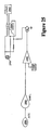
- Figure 29 depicts a conceptual wiring diagram for a transfill switch 2901 for completing a compressor 2904 power circuit supplied by source 2902 and/or a solenoid 2905 power circuit supplied by source 2903.
- Compressor 2904 is normally off during liquefaction.
- Solenoid valve 656 is normally open, but may be closed during transfill in order to permit a pressure buildup inside dewar 620.
- Transfill switch 2901 may be depressed, for example, with the bottom of a portable stroller or portable dewar as it is engaged with a transfill valve; transfill switch may then complete the compressor 2904 circuit and/or the solenoid 2905 circuit.
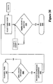
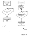
- Figure 30 depicts a transfill time-out flow chart, according to various embodiments of the present invention.
- the transfill of liquid oxygen to a portable stroller may be activated through a state change on the input of a programmable logic device, which may operate to activate the compressor 646, close the solenoid valve 656, monitor the time since transfill began, and terminate the transfill after a predetermined time.
- a programmable logic device which may operate to activate the compressor 646, close the solenoid valve 656, monitor the time since transfill began, and terminate the transfill after a predetermined time.
- Various devices may be used to implement elements of the flow diagram of Figure 30 ; for example, such devices include, but are not limited to, a microcontroller and/or processor, discrete hardware semiconductors, and/or programmable logic devices.
- a method may be used to stop the transfill process after a predetermined time to prevent over-filling of a portable stroller or portable dewar.
- a transfill timing process begins at block 3001. A determination is made whether the transfill switch is enabled (block 3002). If the transfill switch is not enabled, the process continues just before block 3002. If the transfill switch is enabled, then the compressor and solenoid are enabled (block 3003), as described with reference to Figure 29 , above. A timer count is started (block 3004), using a clock in some cases. A determination is made whether the timer count equals a predetermined count (block 3005); for example, a determination is made whether the timer count equals two minutes. As another example, the predetermined count may equal one minute and forty seconds.
- the predetermined count or predetermined time may be any time based on the expected volume of container to be filled and/or the flow rate of liquid gas into the container. Any such predetermined time may also take into account the fact that during the beginning of a transfill process, no liquid gas is transferred between the dewar and the portable stroller because the liquid gas initially boils off in making the transfill apparatus cold enough to convey the liquid gas. If the timer count does not equal the predetermined count, then the timer count is positively incremented and the process returns to a point just before block 3005. If the timer count equals the predetermined count, then the transfill time process ends (block 3006).
- FIG. 13 illustrates a portable stroller 1368 interface according to some embodiments of the present invention.
- the transfill process begins when female valve 1377 on stroller 1368 is aligned with the transfill valve 1364 and pushed onto the transfill valve 1364 in the direction indicated by arrow 1367; a transfill switch 1366 may be configured to activate when a female valve 1377 on the stroller 1368 is engaged with the transfill valve 1364.
- transfill switch 1366 is a push-button switch that may be pushed or pressed by a valve interface surface 1397 of portable stroller 1368 when female valve 1377 of portable stroller 1368 has been engaged with valve 1364.
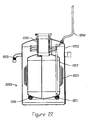
- Figure 24 illustrates a partial cross-sectional view of a male transfill valve 2466 and female valve 2467 interface, usable in some embodiments of the present invention.
- a gas liquefaction device may have mounted therein a valve mount 2473 in fluid communication with a transfill tube, such as a tube extending between valve mount 2473 and a dewar operable to contain a liquid gas.
- the valve mount 2473 may have a threaded inner diameter onto which a valve body 2475 having a threaded outer diameter may be attached.
- Valve body 2475 may include a fluid passage 2465 through which fluids such as liquid oxygen may flow.
- a valve stem 2481 may be situated within fluid passage 2465 and configured to close fluid passage 2465 until depressed.
- Female valve 2467 may include a valve body 2479 having a threaded outer diameter, for example, in order to be attached to a portable stroller.
- Female valve 2467 may also include a fluid passage 2463 and a valve stem 2477, the valve stem 2477 being situated within fluid passage 2463 and configured to close fluid passage 2463 until depressed.
- Valve stem 2477 may also be biased in a closed position via one or more springs (not shown).
- female valve 2467 When a portable stroller comprising female valve 2467 is interfaced with a portable use liquefaction device having a transfill valve 2466, female valve 2467 may be pressed onto transfill valve 2466 to press valve stem 2481 into valve stem 2477, thereby opening fluid passage 2465 and fluid passage 2463 as shown in Figure 24 to allow liquid gas, such as liquid oxygen, to flow from a dewar into a portable stroller.
- a Teflon ring 2461 may be used between female valve 2467 and transfill valve 2466 to temporarily seal the valve interface while valve 2467 is pressed onto valve 2466, to prevent leakage of liquid gas during a transfill process.
- transfill valve 2466 and/or female valve 2467 may be specially adapted to be incompatible with traditional USP transfill valves.
- USP transfill valves may be used to transfer USP 99% purity liquid oxygen from a dewar to a portable stroller; however, government regulatory entities may require that USP93 approved strollers be incompatible with USP transfill valves.
- USP93 approved strollers be incompatible with USP transfill valves.
- One embodiment of a solution to such a problem is made possible by the existence of a de facto standard valve interface for USP portable strollers.
- valve mount 2473 having an outer diameter 2471 greater than an inner diameter of a standard USP valve interface, such that the standard USP valve interface of a USP portable stroller does not fit over the valve mount 2473 and cannot depress valve stem 2481 of a USP93 oxygen liquefaction device.
- a USP93 stroller may be configured with a female valve 2467 adapted with a larger inner diameter 2469 to fit over valve mount 2473 and/or valve body 2475.
- transfill valve 2466 incompatible with a USP portable stroller may involve making the protruding male portion of valve 2466, such as valve body 2475, shorter than a female cavity of a USP portable stroller valve, such that pushing a USP portable stroller valve onto transfill valve 2466 would not bring the valve stem of the USP portable stroller close enough to valve stem 2481 to open either fluid passage 2463 or fluid passage 2465.
- a portable stroller with a standard USP valve would not fit over transfill valve 2466
- a portable stroller with female valve 2467 could be configured to fit over transfill valve 2466 and/or a standard USP transfill valve. Based on the disclosure provided herein, one of ordinary skill in the art will recognize a variety of ways in which transfill valve 2466 and/or female valve 2467 may be configured and/or modified to be incompatible with a corresponding USP (99% purity) approved valve.
- cryocooler 102 and dewar 120 interface at cryocooler flange 104 and dewar flange 116.
- An O-ring 106 may be placed between dewar flange 116 and cryocooler flange 104 to create a seal between dewar flange 116 and cryocooler flange 104.
- the O-ring 106 may be made with silicon.
- a cold finger 108 having a cold head 110 extends from cryocooler 102 down into the dewar 120.
- a feed flow of concentrated oxygen gas enters a feed tube 112 and is liquefied at the cold head 110, then falls into dewar 120.
- Boiloff gases from dewar 120 exit through vent tube 114.
- a liquid oxygen barrier 118 may be situated between dewar 120 and cryocooler 102 in order to control the flow of gas and expanding liquid when the dewar 120 is tipped onto its side.
- Some prior gas liquefaction devices have typically employed complex and/or expensive condenser structures attached to a cold head of a cryocooler. It has previously been thought advantageous to force a feed gas stream across a cold surface enclosure in order to improve liquefaction efficiency. It has also previously been thought advantageous to employ a cooled structure, such as a double-walled condenser structure attached to a cold surface of the cryocooler, and to direct the feed gas through the condenser structure to increase surface area over which liquefaction occurs.
- examples described simply employ a cold finger 108 structure with a cold head 110, at which oxygen gas liquefies.
- examples permit oxygen gas to be introduced in the vicinity of cold finger 108 through feed line 112. Due to the very cold temperatures produced by cold finger 108, a low-pressure area is created at the surface of cold finger 108; this low-pressure area, or "cold pressure,” draws the feed stream of gas toward cold finger 108 for liquefaction. Utilizing this concept reduces cost and complexity by eliminating a condenser structure, particularly a complex or double-walled or spiraled condenser structure.
- flow director portion 2065 of liquid oxygen barrier 2061 may surround cold head 110 of cold finger 108, or may stop short of cold head 110, as described below with reference to Figures 20 and 21 , flow director portion 2065 merely directs the flow of gaseous oxygen and other gases, and is not a condenser, according to various embodiments of the present invention.
- Flow director portion 2065 may direct incoming gas through an inside of flow director portion 2065, causing it to remain in the vicinity of cold finger 108 and/or cold head 110.
- Outgoing gas, or vent gas, such as vent gas from dewar 120 may pass along an outside of flow director portion 2065 as it exits through vent line 114.
- a smaller opening between cold head 2110 and flow director portion 2065 may permit liquid oxygen to drip out after liquefaction, while a larger opening on the outside of flow director portion 2065 may permit gases, such as vent gases, to exit the dewar.
- flow director portion 2065 serves to direct gas flow; it may also serve to prevent liquefaction of ambient air directly following a transfill process.
- liquefaction devices depicted in Figure 1 may also reduce liquefaction cost by seeking to maintain the oxygen purity of incoming gas, rather than seeking to maximize oxygen purity of incoming gas.
- the apparatus depicted in Figure 1 may produce liquid oxygen with an oxygen purity approximately at or just above the oxygen purity of the incoming feed stream supply of oxygen gas. This may be achieved, for example, by fixing the flow rate of the feed stream of oxygen from concentrator 530, using regulator 540 and orifice 542, and by maintaining the cold finger 108 at a substantially constant temperature at or below the liquefaction temperature of oxygen.
- Many oxygen concentrators output oxygen gas with a USP93 purity.
- Examples may therefore liquefy a feed flow of USP93 oxygen gas to maintain purity by creating liquid oxygen with a USP93 purity, rather than liquefying a feed stream of USP93 gas to maximize liquefaction purity.
- Such maximization often requires more complex controllers and hardware, often greatly increases the cost of oxygen liquefaction for small-scale home or office use, and therefore stands as a common drawback associated with prior art devices.
- the efficient and effective maintenance of oxygen purity made possible at least in part by the particular designs, structures, operations, and placements of cryocooler 102, dewar 120, feed line 112, vent line 114, cold finger 108, and other liquefaction-related structures.
- the cryocooler 102 may remain at a substantially constant temperature until the dewar 120 is full. If all of the feed stream of gas were liquefied, oxygen purity of the liquefied gas would remain the same as the oxygen purity of the feed stream of gas.
- such systems may maintain or slightly improve oxygen purity of the liquefied gas compared to the purity of the feed flow of gas for the following reasons: the three primary components of air have the following boiling points (liquefaction temperature): oxygen 90.2 K, argon 87.3 K, and nitrogen 77.4 K. Even at a cold finger 108 tip temperature colder than 77 K, if a positive feed flow is maintained, not all of the feed stream of gas will be liquefied and a slightly greater relative percentage of oxygen will liquefy versus argon and nitrogen. If the equilibrium temperature of such liquefaction systems is 87 K, then only oxygen and argon would liquefy.
- a similar phenomenon may also occur after liquefaction with preferential boiloff due to the different boiling point temperatures of these three gasses. Because oxygen has a higher boiling point temperature than argon or nitrogen, a slightly lower percentage of oxygen boils off due to dewar 120 thermal inefficiencies. Even though preferential boiloff continues to occur after the liquid gas is transferred from the storage dewar 120 in the liquefaction device to the portable dewar from which a patient may breathe, the product gas will still maintain a purity at or greater than the initial feed gas prior to liquefaction. This is due to the preferential liquefaction, and the preferential boiloff during storage and transfer that has already taken place increasing the liquid purity prior to a patient's breathing of the gas from the liquid portable stroller.
- the liquid oxygen can flow out of the mouth of the dewar 120 into the cryocooler flange 104.
- This area may be very warm with a large mass of metal, and may provide direct access to the feed tube 112 and vent tube 114.
- the sudden warming of the liquid oxygen may cause the liquid to quickly boil resulting in a rapid volumetric expansion. This rapid expansion may force liquid oxygen along with gaseous oxygen through the feed tube 112 and vent tube 114 and may result in a spray of liquid oxygen out of a vent port of the liquefaction device.
- a liquid oxygen barrier 118 may be configured to significantly slow down the rate at which liquid oxygen escapes from the insulated dewar 120 during a tipping event.
- the liquid oxygen barrier 118 reduces the size of the opening out of which liquid oxygen may escape during tipping.
- the liquid oxygen barrier 118 may have a diameter smaller than a diameter of the cryocooler flange 104, or the dewar flange 116, or both.
- the liquid oxygen barrier 118 may be a separate piece inserted between the cryocooler flange 104 and the dewar flange 116, or may be inserted into the cryocooler flange 104 only, or may be inserted into the dewar flange 116 only.
- the liquid oxygen barrier 118 may be integrated into either the cryocooler flange 104 or the dewar flange 116.
- Figure 3 depicts a liquid oxygen barrier 318 inserted between cryocooler flange 304 and dewar flange 316.
- O-ring 306 helps to create a seal between cryocooler flange 304 and dewar flange 316.
- Concentrated gas enters feed tube 312 prior to liquefaction; boiloff gas from dewar 320 leaves through vent tube 314.
- the liquid oxygen barrier 318 may allow a building pressure to vent upon tipping of the dewar 320, the pressure is allowed to vent at a controlled and safe rate.
- the liquid oxygen barrier 318 restricts an opening, around cold finger 308, between the dewar 320 and the cryocooler 302 to a smaller opening 301 of which the difference between an inner diameter and an outer diameter of the smaller opening 301 is approximately ten to fifteen thousandths of an inch (0.25-0.38 mm).
- Smaller opening 301 may be located within an annular channel 395, the annular channel formed or defined by the cryocooler flange 304 and/or dewar flange 316 on an outer side, and by the cold finger 308 and/or cryocooler 302 on an inner side, as depicted in Figure 3 .
- annular channel 395 may be formed or defined by the cryocooler 302 and/or dewar 320 on an outer side, and by the cold finger 308 and/or cryocooler 302 on an inner side, as depicted in Figure 3 .
- Barrier 318 may serve to narrow the width of annular channel 395, and/or reduce the cross-sectional area of annular channel 395, such as at smaller opening 301. With barrier 318 in place, gas is still permitted to flow between the cryocooler 302 and the dewar 320; however, when the dewar 320 is tipped or tilted, barrier 318 may serve to decrease the rate at which a rapidly-expanding mixture of gas and liquid gas is permitted to exit the dewar 320 into the cryocooler 302.
- the liquid oxygen barrier 318 may be constructed of Teflon.
- the barrier 318 may be positioned, inserted, or interposed between cryocooler flange 304 and dewar flange 316; in such examples, clamping element 1831, 1931 (see Figure 18 , for example) may secure barrier 318 in place while simultaneously clamping cryocooler flange 304 and dewar flange 316 together over O-ring 306.
- barrier 318 may be integral with cryocooler 302, dewar 320, and/or cold finger 308.
- Figure 19 also depicts a side perspective, cut-away view of an inside of a cryocooler and dewar interface of one example, showing a cold finger and a liquid oxygen barrier 1918.
- Liquid oxygen barrier 2061, 2161 comprises a liquid oxygen barrier portion 2063 and a flow director portion 2065.
- Flow director portion 2065 extends the length of a cold finger 2108.
- Flow director portion 2065 may alternatively extend the length of a cold finger 2108 including a cold head 2110.
- Flow director portion 2065 may be tubular; alternatively, flow director portion 2065 may be of any shape that surrounds the cold finger 2108 and directs a feed gas flow from the feed line 512 towards the cold head 2110.
- liquid oxygen barrier 2061, 2161 may be constructed with a Teflon material.
- Feed flow enters from a feed flow line 512 through opening 2069 and flows inside of the flow director portion 2065 toward the cold head 2110. Vent gas flows along the outside of the flow director portion 2065 and out to the vent line 514 through opening 2067.
- the liquid oxygen barrier portion 2063 though of a different configuration in order to allow feed gas to flow inside and vent gas to flow outside, performs the same function as the liquid oxygen barriers 118, 318, 1918 in preventing excessive leakage of liquid and gaseous oxygen during a tipping event.
- Figures 9-11 depict perspective views of a lower chassis assembly of a liquefaction device. Shown in Figures 9-11 are feed tube 912, 1012; vent tube 914, 1014; solenoid valve 1056; relief valve 1054 for the feed tube 1012; filter 1052; relief valve 1158 for the vent tube 1014; vent port 1170; and boiloff tube 1160.
- feed tube 1012 and/or vent tube 1014 are one quarter inch (6 mm) inner diameter vinyl tubing.
- mounting slots 1172 onto which an upper chassis assembly may be inserted.
- FIGS 12 and 13 depict a perspective view of the outer housing 1280 of a liquefaction apparatus according to one example, showing a possible placement of a detachable humidifier 1284.
- Humidifier bottle 1284 is attached to patient flow tube 534.
- a humidifier may not be used at the outlet of the oxygen concentrator 530 because the liquefaction process cannot tolerate water vapor mixed with oxygen.
- the humidifier bottle features an attachment nozzle 1286 for attaching a canula.
- Patient flow meter 1238 allows a patient to adjust flow rate of oxygen received.
- the top of the outer housing 1280 features an indentation 1282 in the shape of the bottom of a portable stroller 668 to facilitate fitting the stroller 668 over transfill valve 1264.
- the indentation 1282 also accommodates the portable stroller 668 in order to allow the portable stroller 668 to depress a transfill switch 666.
- Indentation 1282 may be a depression formed on outer housing 1280, shaped to fit a valve interface surface 697 of portable stroller 668.
- the stroller 668 also has a valve that interfaces specifically with transfill valve 1264, such that when the stroller 668 is engaged onto the transfill valve 1264, a connection opens between the two valves allowing fluid to flow freely between them.
- the outer housing 1280 has handles 1288.
- Handles 1288 may facilitate patient handling and movement of the liquefaction device. Handles 1288 may also be configured to allow a canula to be wrapped around them for storage while the canula is not in use.
- handles may be secured into the outer housing 1280 with fasteners that are also operable to hold wires in the correct place along the inside of the outer housing 1280. For example, if the handles 1288 are secured to the outer housing 1280 with screws, a wire on the inside of the outer housing 1288 may be laid under a strap secured to the inside of the outer housing 1288 between two screw heads, thus securing a placement of the wire.
- the handles may be integral to the outer housing 1288.
- Figure 14 depicts a top perspective view of the outer housing 1480 of a liquefaction device according to one example, showing a transfill valve 1464 and transfill switch 1466.
- FIG. 15 depicts a side perspective view of a cryocooler 1502 and dewar 1520 secured by a mounting shroud 1590 to an upper chassis 1594 of a liquefaction device according to one embodiment of the present invention.
- the mounting shroud 1590 comprises a cooling fan mount 1592.
- the upper chassis 1594 has mounting pegs 1596 that fit into mounting slots 1172 (see Figure 11 ) on a lower chassis.
- mounting shroud 1590 is secured to upper chassis 1594 via vibration dampeners 1598.
- vibration dampeners 1598 greatly reduce noise due to vibration by isolating the cryocooler 1502 and mounting shroud 1590 from the upper chassis 1594 at the places where the mounting shroud 1590 contacts the upper chassis 1594: the four mounting bolts.
- Vibration dampeners 1598 may be made with rubber.
- vibration dampeners 1598 may be made with Buna-N rubber.
- vibration dampeners 1598 may be made with any other vibration-dampening materials or devices.
- vibration dampeners 1598 may comprise a spring dampener assembly.
- Figure 16 depicts a perspective view of a back side of the mounting shroud 1690 and dewar 1620.
- the shape of the inside of the mounting shroud 1690 may be such that it directs airflow over a cooling fin of a cryocooler.
- a fan may be mounted in fan housing 1692 to pull air in the direction indicated by arrow 1675. Consequently, air enters the air intake 1671 in the direction indicated by arrow 1673, blows over a cooling fin of the cryocooler, and exits the mounting shroud 1690 through fan housing 1692.
- Figure 17 shows a partial cutaway view of the mounting shroud 1790, revealing cryocooler 1702 and cryocooler cooling fin 1711.
- FIG. 18 depicts an interface between a cryocooler flange 1804 and a dewar flange 1816 according to one example.
- the mounting shroud 1890 may comprise two separate pieces.
- the mounting shroud 1890 may alternatively comprise two halves. Two mounting shroud halves may be bolted together through bolt holes such as bolt hole 1677.
- the mounting shroud 1890 comprises a clamp, or clamping element, 1831, 1931.
- Clamping element 1831, 1931 encompasses at least a portion of both cryocooler flange 1804 and dewar flange 1816, as shown in Figure 18 .
- the cryocooler flange 1804 may include a sloped portion surface leading out from a neck portion 1835 of the cryocooler, as the outer diameter of cryocooler flange 1804 increases as it approaches dewar flange 1816.
- Dewar flange 1816 may also include a corresponding sloped portion surface leading out from a neck portion 1833 of the dewar, as the outer diameter of dewar flange 1816 increases as it approaches cryocooler flange 1804.
- Clamp 1831, 1931 may be configured to conform to the sloped portion surfaces of dewar flange 1816 and cryocooler flange 1804, in order to, for example, apply a normal force thereto.
- the compression of the O-ring 106 that follows application of the clamping element 1831, 1931 serves to prevent the cryocooler flange 1804 and dewar flange 1816 interface from leaking either gaseous or liquid oxygen, even when tipped over.
- a cold finger 408 extends into dewar 420.
- Cold finger 408 has a temperature gradient.
- One end 413 of cold finger 408 has a temperature higher than the boiling point of oxygen, and another end 415 has a temperature lower than the boiling point of oxygen.
- the liquid level 417 rises only to a level on the cold finger 408 at which the temperature exceeds the boiling point of oxygen.
- no exposed part of the cold finger 408 is cold enough to liquefy oxygen, so the liquid level 417 does not rise further; this prevents overfilling of the dewar 420.
- a cryogenic liquid level sensor 789 may be used to trigger a system shutdown when the liquid level in the dewar exceeds a predetermined limit.
- Figure 7 depicts a side view of a cryogenic liquid level sensor 789 of one example.
- Parallel plates 783 may be held together with non-conductive screws 781 on either side of a mounting plate 785; cryogenic liquid level sensor 789 may be coupled to top of dewar 820 and extend the length of the dewar 820, as depicted in Figure 8 .
- a capacitive method of measuring the level of liquid gas, such as liquid oxygen, in a dewar may be utilized. This method may use parallel plates 783 or parallel cylinders (not shown).
- the gaseous oxygen between parallel plates 783 is gradually replaced with liquid oxygen.
- the dielectric-constant change between gaseous oxygen and liquid oxygen varies the capacitance measured between parallel plates 783.
- This capacitance change corresponds to the liquid level change in the dewar 820, and may be measured and converted to a usable form for display to a user.
- the liquid level in the dewar can be displayed in a bar-lamp format with a resolution of 1 ⁇ 4 dewar (1/4, 1/2, 3/4, full). Alternatively the liquid level in the dewar 820 can be displayed in a digital readout.
- a capacitor cryogenic liquid level sensor 789 may be constructed of two or more metal electrically conductive plates separated by a non-conductive material having a fixed dielectric constant, such as a dielectric constant greater than 1.0. Such a cryogenic liquid level sensor 789 may be used to measure the liquid level of liquid oxygen or nearly any other cryogenic liquid. Cryogenic oxygen liquid level sensor 789 may measure the difference of the change in the dielectric constant of oxygen between the gaseous phase and the liquid phase. This creates a variable capacitance directly related to liquid height. A number of different displays of liquid level may be possible with the use of cryogenic liquid level sensor 789.
- cryogenic liquid level sensors may be used, according to alternative examples.
- a float may be used to measure cryogenic liquid level in a manner similar to the manner in which a float may be used as a common automotive fuel level sensor.
- a float arm moves through a variable resistance as the float moves up or down on the surface of the desired liquid.
- This variable resistance produces a variable voltage from a known voltage source, and the variable voltage may be connected to a voltage meter or the like for display.
- a resistance method may be used.
- Such methods may, for example, utilize the thermal conductivity constant for copper (3.98 watts per centimeter - Kelvin), and the resistivity constant of copper, to sense the point between the gaseous phase and the liquid phase of the cryogenic liquid.
- a level point between the gaseous phase and the liquid phase has a differential temperature change, such as a differential temperature change of a few degrees, and thus a difference in the thermal conductivity because the gaseous phase conducts more power than the liquid phase.
- the liquid height may be calculated based on the level of the liquid phase as sensed by the amount of power conducted to the gaseous phase; a lower power conducted to the gaseous phase may correspond to a higher liquid level.
- semi-conductor methods may be used.
- Such methods may employ a special diode construction whose conduction properties change when exposed to cryogenic temperatures; in some instances, the special diode construction may be an individual point(s) monitoring device controlled via a microcontroller/processor.
- cryogenic liquid level sensors ultra-sonic methods may be used. Such methods may use a pulsed high or ultra-high frequency ultrasonic transducer to measure the "Doppler Effect" of the reflected signal from the surface of the measured liquid. A shorter "Doppler Effect" measurement corresponds to a higher cryogenic liquid level.
- FIG 22 depicts an efficient dewar 2220 design.
- Liquid oxygen may be stored in an inner vessel 2217.
- the inner vessel 2217 is contained by the outer vessel 2215.
- Between the inner vessel 2217 and outer vessel 2215 is a near-vacuum space to minimize convective heat transfer.
- a wrapping material 2219 such as SuperWrap, is wrapped around the inner vessel 2217 to slow radiant heat transfer.
- Cold getters 2211 capture errant moisture molecules from within the vacuum space.
- a warm surface getter 2213 captures hydrogen molecules from within the vacuum space.
- a transfill tube 2262 reaches through the inner vessel 2217, then wraps several times around the bellows neck 2221, then exits through the outer vessel 2215.
- bellows neck 2221 By increasing the length of the transfill tube 2262 within the vacuum space, and by narrowing the cross-sectional area of the tube 2262, conductive heat losses are minimized. Conductive heat losses are also minimized by the bellows neck 2221.
- the inner vessel 2217 is coupled to the outer vessel 2215 by bellows neck 2221.
- Bellows neck 2221 may have an accordion shape, as depicted in Figure 22 , in order to increase the length of the path that heat must travel to escape. Other bellows neck 2221 designs may be employed to increase the length of the path that heat must travel to escape.
- a fin temperature sensor 299 may be located in proximity to a cooling fin of a cryocooler. Additionally, a cold finger temperature sensor 297 may be located in proximity to a cold finger of a cryocooler.
- the fin temperature sensor 299 may detect potentially hazardous or damaging conditions; for instance, sensing a fin temperature that is too high may indicate that the cooling fan has failed and the cryocooler is overheating.
- the fin temperature sensor 299 may also detect whether the liquefaction apparatus has been placed in sunlight, an excessively warm room, or whether its cooling vents have been obstructed.
- Cold finger temperature sensor 297 may detect if a displacer in the cryocooler has seized, causing the cold finger to warm up rather than cool down.
- cold finger temperature sensor 297 may alternatively be located inside of flow director portion 2065.
- a circuit latches a "halt" signal to the cryocooler control and stops the motor.
- An indicator lamp for the user may be illuminated during this fault.
- the "halt" signal may be released by recycling power to the liquefaction apparatus, unless the excessive temperature condition is still present.
- Figure 27 depicts a conceptual wiring diagram for a temperature sensing circuit to turn off electrical components of a liquefaction system, according to various examples.
- a signal conditioner may be coupled with temperature sensors or thermocouples 2701, 2702. The signal conditioner outputs a temperature signal corresponding to one, both, or more of temperature sensors 2701, 2702.
- temperature sensor 2701 may be located and/or configured to measure the temperature near a cooling fin of a cryocooler 2704, also known as the reject temperature.
- temperature sensor 2702 may be located and/or configured to measure the temperature near a cold finger of a cryocooler 2704. The signal is compared to a reference voltage by a comparator 2707.
- cryocooler PWM control 2706 When either temperature sensor 2701, 2702 senses a temperature that is too high, the depicted circuit latches a "halt" signal to the cryocooler PWM control 2706 and stops the motor of cryocooler 2704 by breaking the electrical power circuit supplying power from source 2705 to cryocooler 2704. Power may be removed from cryocooler 2704 when either temperature sensor 2701 or temperature sensor 2702 senses a temperature that is too high; for example, in some versions, temperature sensor 2701 may sense a cryocooler cooling fin temperature above sixty-five degrees Celsius, or temperature sensor 2702 may sense a cold finger temperature above fifty degrees Celsius. An indicator lamp for the user may be illuminated during this fault. The "halt" signal may be released by recycling power to the liquefaction apparatus, unless the excessive temperature condition is still present.
- Figure 25 depicts a conceptual wiring diagram for an impact-sensing mechanism to turn off electrical components of a liquefaction system, according to various examples.
- Power supplied by source 2506 to a load 2505 is passed through an actuated contact assembly (i.e. circuit breaker or relay or semi-conductor circuit). As long as power is applied to the actuator mechanism 2504, power is allowed through the contact assembly.
- the sensing output of an accelerometer 2501 or other impact sensing device 2501 is amplified into a desired range by amplifier 2502. This voltage range is input into an analog-to-bit converter and compared to a known voltage at comparator 2503. The "bit" output triggers a switching device.
- a circuit protector device removes the power to the actuator mechanism 2504 and removes power to the load 2505.
- Load 2505 may be, but is not limited to, the cryocooler, cryocooler driver, cooling fan, circuit boards, and/or any other element that operates via electrical power.
- FIG. 26 depicts a conceptual wiring diagram for a tip-over or tilt switch to turn off electrical components of a liquefaction system.
- Tip/tilt switch 2601 may be any switch capable of changing states, from “on” to “off” or from “off” to “on,” when tip/tilt switch 2601 experiences a rotation in angle or inclination.
- Tip/tilt switch 2601 may be affixed to a dewar, cryocooler, and/or any other element of a gas liquefaction system to determine when the element to which it is attached has been tipped and/or tilted.
- tip/tilt switch 2601 may be a mercury switch.
- Tip/tilt switch 2601 may be configured to change states upon tipping or tilting through a predetermined angle; for example, the predetermined angle may be forty-five degrees. Alternatively, the predetermined angle may be any angle indicative of a tipover or excessive tilting event; for example, the predetermined angle may be an angle in the range from thirty degrees to sixty degrees.
- Power from a source 2606 to a load 2605 is passed through an actuated contact assembly (i.e. circuit breaker or relay or semi-conductor circuit). As long as power is applied to the actuator mechanism 2604, power is allowed through the contact assembly.
- actuated contact assembly i.e. circuit breaker or relay or semi-conductor circuit.
- tip/tilt switch 2601 triggers to remove power to the actuator mechanism 2604, thereby removing power to the load 2605.
- Load 2505 may be, but is not limited to, the cryocooler, cryocooler driver, cooling fan, circuit boards, and/or any other element that operates via electrical power.
- Figure 28 depicts a conceptual wiring diagram for measurement of oxygen purity and display options for displaying oxygen purity.
- oxygen purity sensing may be measured with a Galvanic-type micro-"fuel-cell" method, or with a light refraction method.
- Each oxygen purity sensing element may provide a different usable output, and each may require its own conversion circuitry.
- each possible method for displaying oxygen purity information may require its own conversion circuitry and/or method.
- oxygen purity sensor 568 may be located in feed flow line 512.
- oxygen purity sensor 568 may be located in fluid communication with feed flow line 512 and/or inline with feed flow line 512 anywhere prior to liquefaction. If oxygen purity sensor 568 is sensitive to input pressure, oxygen purity sensor may be placed in feed flow line 512 downstream from pressure regulator 540 and/or orifice 542.
- a sensor 2801 such as a "fuel-cell” sensor, may be used to measure oxygen purity.
- a sensed oxygen purity may be displayed through various graphical representations, such as, for example, numerical LED indicators 2803, purity bar LED indicators 2804, and/or colored LEDs 2805.
- the usable sensing output of the "fuel-cell” may be, but is not limited to, a signal corresponding to millivolts per percent of oxygen. This signal may be amplified into a required voltage range. When using a simple pass/fail type of information display, the amplified signal may be input to a series of analog-to-bit converters.
- a display driver 2802 may then switch ON independent LED's or lamps to indicate a pass/fail condition of the gaseous oxygen purity level.
- display driver 2802 may display a numerical purity measurement via numerical LED indicators 2803.
- display driver 2802 may display a graphical purity measurement via a purity bar LED indicator 2804.
- display driver 2802 may display a pass/fail purity measurement via green, yellow, and/or red LEDs 2805; in such cases, activation of a green LED may signal a satisfactory oxygen purity level, activation of a yellow LED may signal a potential though not necessarily serious problem with oxygen purity, and activation of a red LED may signal a serious or dangerously low oxygen purity level.
- the satisfactory oxygen purity range may be a purity greater than 85% oxygen by volume.
- FIG 31 depicts a conceptual wiring diagram illustrating a cryocooler low power mode.
- the cryocooler continues to run, but does not continue to liquefy oxygen. This is due to the liquid level rising to a point on the cold finger such that no exposed portion of the cryocooler's cold finger is colder than the liquefaction temperature of oxygen.
- Continuing to run the cryocooler at full power with a full dewar may result in an over-expenditure of energy.
- electrical power may be removed completely from the cryocooler when a full dewar is sensed, lowering power instead of removing power may reduce wear on cryocooler components and eliminate any potential noise associated with a cryocooler cold start.
- a low-power mode of the cryocooler and/or cooling fan includes, but are not limited to, a reduced noise level, a reduction in excess heat generation, reducing liquid boiloff rate for liquid gas within the dewar, and/or decreasing cryocooler wear.
- Implementing a low-power mode of the cryocooler and/or cooling fan may reduce power consumption by over fifty percent while the dewar is full, and may reduce power consumption by thirty to thirty-five percent overall.
- a low-power or energy-saving mode may be initiated when the cryogenic liquid level sensor senses a full liquid level in the dewar, and may return to a normal mode when the cryogenic liquid level sensor senses a predetermined liquid level in the dewar; for example, the low power mode may return to the normal mode when the cryogenic liquid level sensor senses a three-fourths full liquid level in the dewar.
- a low power mode may be entered by simply reducing the power supplied to the cryocooler and/or cooling fan to a predetermined power level.
- Figure 31 shows a circuit operable to reduce power to the cryocooler driver 3102.
- the full PWM setpoint 3101 voltage may be applied to the cryocooler driver 3102.
- the cryogenic liquid level sensor supplies a liquid level voltage 3103 that may be amplified and compared with a reference voltage to determine when the liquid level is full and thus when the low-power mode should be entered.
- a switching device provides a ground path through an additional resistance, creating a voltage divider reducing the voltage applied to the cooler driver 3102 circuitry.
- the applied power may be set to a wide range of possible powers, depending on the energy consumption requirements of the cryocooler, and the fluid flow and/or thermodynamic characteristics of the given liquefaction system. According to some examples, the applied power may be selected to keep the piston within the cryocooler centered but not displacing through its full range.
- FIG. 32 depicts a conceptual wiring diagram illustrating an alternating current cooling fan low power mode.
- a first circuit diagram 3201 illustrates a low power mode for an alternating current fan 3203 supplied with power by source 3204.
- a full setpoint voltage is applied to a PWM/Random phase controller 3205 having a timer 3206, and applies full voltage to the cooling fan 3203.
- a switching device may be activated creating a ground path through a second resistance.
- Such a switching device may be activated when a cryogenic liquid level sensor supplies a liquid level voltage 3207 signal that exceeds a reference voltage. This creates a voltage divider circuit and reduces the voltage setpoint for the PWM/random phase fan driver 3205 and slows the fan speed.
- FIG. 33 depicts a conceptual wiring diagram illustrating a direct-current cooling fan low-power mode.
- a second circuit diagram 3202 illustrates a low-power mode for a direct-current fan 3208.
- fan speed may be automatically reduced or increased to maintain a constant cryocooler reject temperature (or cooling fin temperature) at a predefined temperature.
- the reject temperature may be monitored and compared to a setpoint. Based on this difference, a switching device may be pulsed at a higher or lower rate by the PWM controller 3209, controlling the fan 3208 air flow and set temperature of the cryocooler.
- the system eventually arrives at equilibrium, at which the temperature of the cold finger tip may depend on a combination of factors, including, but not limited to, the cooling efficiency of the cryocooler and the thermal load to which the cryocooler is subjected.
- the thermal load experienced by the cryocooler may depend on factors including, but not limited to, the flow rate of gas directed across the cold finger, the inlet temperature of the gas, and the thermal inefficiencies of the dewar and dewar seal flange. Because variations may exist in all of these parameters based on physical differences between separately manufactured components, an inlet power to the cryocooler should be set high enough to accommodate for the worst-case variation.
- cryocooler power setting may result in the cryocooler drawing a power greater than the power necessary to achieve an adequate liquefaction rate. Such extra power would generally further reduce the temperature of the cold finger during liquefaction.
- a low-power mode may be entered by monitoring the temperature of the cold end of the cold finger and adjusting power input to the cryocooler to maintain a predetermined cold end temperature during a low-power mode.
- liquid may be produced until the dewar is filled, then the power supplied to the cryocooler may be reduced while monitoring the cold finger tip temperature.
- the predetermined cold end temperature may be found by experimentally varying the temperature until a temperature is found that maintains the liquid volume within the dewar measured by a scale. Such a method may, in some cases, permit a more cost-effective and energy-saving design of a liquefaction system, and may also compensate for potential decrease in cryocooler efficiency over time.
- a liquefaction apparatus may also employ other electronic systems to improve safety, efficiency, and cost. For instance, when power is first applied to the system, all the user indicator lamps may be activated to allow a user to verify that all lamps work properly; after a short period of time, the lamps, except for the power lamp, may be deactivated and the system may enter normal operation.
- cryocooler firing angle may be varied so that the proper RMS voltage is applied to the linear motor, maintaining the desired piston stroke, as external operating conditions change.
- a piston stroke control loop compares the stroke set-point to the piston amplitude from a re-construction circuit. This may be accomplished by controlling the firing angle to a random-phase, opto-isolation Triac-driver.
- the firing Triac device and the front-end re-construction circuit may be electrically isolated from the control and feed-back circuitry.
- the stroke of the cryocooler piston may be estimated using an isolated back-EMF of the motor and an isolated monitoring of the motor current.
- the cryocooler piston is lifted to its maximum state by rectifying the AC voltage and controlling the resultant DC power to the cooler. This is accomplished by controlling the firing angle to a random-phase, opto-isolation Triac-driver and the use of a full-wave Diode-Bridge and a Triac combination.
- FIG. 34 depicts a flow diagram 3400 illustrating a method for maintaining oxygen purity in liquefaction of gas for residential oxygen therapy.
- a feed stream of gas is received from an oxygen concentrator (block 3402).
- a cryocooler is provided, the cryocooler including a cold finger, and the cold finger extending within a container and operable to liquefy the gas for containment in the container (block 3404).
- the cold finger may be maintained at a substantially constant temperature at or below the liquefaction temperature of oxygen (block 3406).
- At least part of the feed stream of gas is liquefied, the oxygen purity of liquefied gas being substantially at or greater than the oxygen purity of the feed stream of gas (block 3408).
- the feed stream of gas may be drawn to the cold finger at least in part with a low pressure created by liquefaction of the feed stream of gas at a surface of the cold finger (block 3410).
- Liquefied gas may be accumulated in the container (block 3412).
- a portable dewar may be provided to store the liquefied gas for ambulatory medical gas therapy (block 3414), and the liquefied gas may be transferred from the container to the portable dewar (block 3416).
- FIG. 35 depicts flow diagrams illustrating a method for reducing power consumption in residential medical gas liquefaction and storage and a method for initiating a low-power mode of a cryocooler.
- Flow diagram 3500 illustrates a method for reducing power consumption in residential medical gas liquefaction and storage.
- a feed stream of gas may be received from an oxygen concentrator (block 3502).
- a cryocooler may be provided, the cryocooler including a cold finger, and the cold finger extending within a container and operable to liquefy at least part of the feed stream of gas for containment in the container (block 3504).
- a liquid level sensor may be mounted within the container, the liquid level sensor operable to detect a liquid level in the container (block 3506).
- Flow diagram 3501 illustrates a method for initiating a low power mode of a cryocooler.
- a maintenance temperature may be selected (block 3512), and the temperature of the cold finger may be monitored (block 3514).
- the power supply to the cryocooler may be varied in order to maintain the temperature of the cold finger at the maintenance temperature (block 3516).
- Figure 36 depicts flow diagrams 3600, 3601 illustrating methods for initiating a low-power mode of a cryocooler.
- Flow diagram 3600 illustrates a method for initiating the low power mode of the cryocooler.
- the power supply of the cryocooler may be reduced to a low power setting (block 3612).
- a determination may be made whether the liquid level in the dewar is at or below the second predetermined liquid level (block 3614). If not, then the liquid level detection may continue (block 3614). If the liquid level in the dewar is at or below the second predetermined liquid level, such as at a three-fourths full level, then the power supply to the cryocooler may be restored to a full power setting (block 3616).
- Flow diagram 3601 illustrates further elements of a method for initiating a low power mode.
- a cooling fan may be provided (block 3618).
- the power supply of the cooling fan may be reduced to a low power setting (block 3620).
- a determination may be made whether the liquid level in the dewar is at or below the second predetermined liquid level (block 3622). If not, then the liquid level detection may continue (block 3622). If the liquid level in the dewar is at or below the second predetermined liquid level, such as at a three-fourths full level, then the power supply to the cooling fan may be restored to a full power setting (block 3624).
Landscapes
- Engineering & Computer Science (AREA)
- Mechanical Engineering (AREA)
- General Engineering & Computer Science (AREA)
- Physics & Mathematics (AREA)
- Thermal Sciences (AREA)
- Health & Medical Sciences (AREA)
- Emergency Medicine (AREA)
- Filling Or Discharging Of Gas Storage Vessels (AREA)
- Separation By Low-Temperature Treatments (AREA)
Applications Claiming Priority (4)
| Application Number | Priority Date | Filing Date | Title |
|---|---|---|---|
| US62248304P | 2004-10-26 | 2004-10-26 | |
| US67766105P | 2005-05-02 | 2005-05-02 | |
| US11/130,646 US7318327B2 (en) | 2004-10-26 | 2005-05-16 | Liquefying and storing a gas |
| PCT/US2005/038716 WO2006047664A2 (en) | 2004-10-26 | 2005-10-25 | Liquefying and storing a gas |
Publications (3)
| Publication Number | Publication Date |
|---|---|
| EP1805451A2 EP1805451A2 (en) | 2007-07-11 |
| EP1805451A4 EP1805451A4 (en) | 2011-08-31 |
| EP1805451B1 true EP1805451B1 (en) | 2014-05-21 |
Family
ID=36204918
Family Applications (2)
| Application Number | Title | Priority Date | Filing Date |
|---|---|---|---|
| EP05824289.2A Expired - Lifetime EP1805451B1 (en) | 2004-10-26 | 2005-10-25 | Liquefying and storing a gas |
| EP05814957.6A Expired - Lifetime EP1805463B1 (en) | 2004-10-26 | 2005-10-25 | Liquefying and storing a gas |
Family Applications After (1)
| Application Number | Title | Priority Date | Filing Date |
|---|---|---|---|
| EP05814957.6A Expired - Lifetime EP1805463B1 (en) | 2004-10-26 | 2005-10-25 | Liquefying and storing a gas |
Country Status (7)
| Country | Link |
|---|---|
| US (3) | US7213400B2 (https=) |
| EP (2) | EP1805451B1 (https=) |
| JP (2) | JP2008518181A (https=) |
| AU (3) | AU2005299616B2 (https=) |
| BR (2) | BRPI0517532A (https=) |
| CA (2) | CA2585356C (https=) |
| WO (2) | WO2006047710A2 (https=) |
Families Citing this family (67)
| Publication number | Priority date | Publication date | Assignee | Title |
|---|---|---|---|---|
| US7213400B2 (en) * | 2004-10-26 | 2007-05-08 | Respironics In-X, Inc. | Liquefying and storing a gas |
| US20060260327A1 (en) * | 2005-05-18 | 2006-11-23 | Shoji Kanamori | Apparatus and method for rapidly freezing small objects |
| AU2006270218A1 (en) | 2005-07-18 | 2007-01-25 | Societe Bic | Separable fuel cartridge |
| US7721733B2 (en) * | 2005-07-29 | 2010-05-25 | Ric Investments, Llc | Portable liquid oxygen delivery system |
| US9782229B2 (en) | 2007-02-16 | 2017-10-10 | Globus Medical, Inc. | Surgical robot platform |
| US7771511B2 (en) | 2006-08-28 | 2010-08-10 | Ric Investments, Llc | Oxygen concentration system and method |
| DE602007010807D1 (de) * | 2006-09-08 | 2011-01-05 | Arbel Medical Ltd | Vorrichtung für kombinierte behandlung |
| US20080208181A1 (en) * | 2007-01-19 | 2008-08-28 | Arbel Medical Ltd. | Thermally Insulated Needles For Dermatological Applications |
| USD568999S1 (en) * | 2007-02-01 | 2008-05-13 | Ric Investments, Llc | Oxygen liquefier connector |
| US8156972B2 (en) * | 2007-04-20 | 2012-04-17 | Ric Investments, Llc | System and method for filling a portable liquified gas storage/delivery system |
| FR2916145A1 (fr) * | 2007-05-14 | 2008-11-21 | Air Liquide | Dispositif de fourniture d'oxygene domestique et ambulatoire |
| US20100162730A1 (en) * | 2007-06-14 | 2010-07-01 | Arbel Medical Ltd. | Siphon for delivery of liquid cryogen from dewar flask |
| WO2009007963A1 (en) * | 2007-07-09 | 2009-01-15 | Arbel Medical Ltd. | Cryosheath |
| US8122882B2 (en) * | 2007-10-29 | 2012-02-28 | Smiths Medical Asd, Inc. | Rainout reduction in a breathing circuit |
| WO2009066292A1 (en) * | 2007-11-21 | 2009-05-28 | Arbel Medical Ltd. | Pumping unit for delivery of liquid medium from a vessel |
| WO2009090647A2 (en) * | 2008-01-15 | 2009-07-23 | Arbel Medical Ltd. | Cryosurgical instrument insulating system |
| ES2341150T3 (es) * | 2008-03-20 | 2010-06-15 | Gruppo Cimbali S.P.A. | Dispositivo de sustitucion de recipientes esteriles que contienen productos concentrados en un aparato para la produccion de bebidas. |
| US8083733B2 (en) | 2008-04-16 | 2011-12-27 | Icecure Medical Ltd. | Cryosurgical instrument with enhanced heat exchange |
| US8875614B2 (en) | 2008-07-28 | 2014-11-04 | Lwrc International, Llc | Adjustable gas block for an indirect gas operated firearm |
| US20100281917A1 (en) * | 2008-11-05 | 2010-11-11 | Alexander Levin | Apparatus and Method for Condensing Contaminants for a Cryogenic System |
| US7967814B2 (en) | 2009-02-05 | 2011-06-28 | Icecure Medical Ltd. | Cryoprobe with vibrating mechanism |
| WO2010105158A1 (en) * | 2009-03-12 | 2010-09-16 | Icecure Medical Ltd. | Combined cryotherapy and brachytherapy device and method |
| US20100305439A1 (en) * | 2009-05-27 | 2010-12-02 | Eyal Shai | Device and Method for Three-Dimensional Guidance and Three-Dimensional Monitoring of Cryoablation |
| CN102812318B (zh) * | 2009-09-28 | 2016-01-06 | 皇家飞利浦电子股份有限公司 | 用于液化和存储流体的系统和方法 |
| US20120180899A1 (en) * | 2009-09-29 | 2012-07-19 | Koninklijke Philips Electronics N.V. | Sytem and method for liquefying a fluid and storing the liquefied fluid |
| US7967815B1 (en) | 2010-03-25 | 2011-06-28 | Icecure Medical Ltd. | Cryosurgical instrument with enhanced heat transfer |
| US10690387B2 (en) | 2010-05-03 | 2020-06-23 | Consejo Superior De Investigaciones Científicas (Csic) | System and method for recovery and recycling coolant gas at elevated pressure |
| ES2617357T3 (es) * | 2010-05-03 | 2017-06-16 | Consejo Superior De Investigaciones Científicas (Csic) | Sistema y método de licuefacción de gas |
| US20130047632A1 (en) | 2010-05-03 | 2013-02-28 | Consejo Superior De Investigaciones Cientificas (Csic) | Gas liquefaction system and method |
| US7938822B1 (en) | 2010-05-12 | 2011-05-10 | Icecure Medical Ltd. | Heating and cooling of cryosurgical instrument using a single cryogen |
| US8080005B1 (en) | 2010-06-10 | 2011-12-20 | Icecure Medical Ltd. | Closed loop cryosurgical pressure and flow regulated system |
| CN102949795B (zh) * | 2011-08-16 | 2014-11-12 | 西安坚瑞安全应急设备有限责任公司 | 一种泄爆型的气溶胶灭火装置内筒 |
| CA2753588C (en) | 2011-09-27 | 2016-01-26 | Westport Power Inc. | Apparatus and method for volume and mass estimation of a multiphase fluid stored at cryogenic temperatures |
| GB2509713B (en) * | 2013-01-09 | 2019-01-02 | The Hymatic Engineering Company Ltd | A container |
| CN103148344A (zh) * | 2013-03-28 | 2013-06-12 | 多立恒(北京)能源技术有限公司 | 液化气钢瓶直阀充气枪 |
| FR3006052B1 (fr) * | 2013-05-23 | 2015-05-01 | Air Liquide Sante Services | Dispositif et procede de mesure de duree de consommation de gaz dans un batiment hospitalier |
| CN103486435B (zh) * | 2013-09-18 | 2015-02-04 | 成都华气厚普机电设备股份有限公司 | 分度式杜瓦瓶螺旋充装器及其使用方法 |
| US20150238721A1 (en) * | 2014-02-24 | 2015-08-27 | Vetland Medical Sales and Services, LLC | Electronic E-Cylinder |
| US9995546B2 (en) | 2015-01-19 | 2018-06-12 | Lwrc International Llc | Adjustable gas block |
| CN111603643B (zh) | 2015-04-02 | 2023-05-23 | 希尔-罗姆服务私人有限公司 | 呼吸装置的压力控制 |
| FR3035194A1 (fr) * | 2015-04-16 | 2016-10-21 | Air Liquide | Installation de fourniture d’oxygene associant un concentrateur d’oxygene a un dispositif autonome de liquefaction de gaz |
| FR3042019B1 (fr) * | 2015-10-01 | 2018-05-18 | L'air Liquide, Societe Anonyme Pour L'etude Et L'exploitation Des Procedes Georges Claude | Reservoir de stockage de gaz liquefie incluant des sondes resistives pour mesurer la hauteur du gaz liquefie |
| CN106764430B (zh) * | 2015-11-20 | 2019-01-08 | 云南冶金新立钛业有限公司 | 煤气的收集方法和装置 |
| RU168325U1 (ru) * | 2016-03-30 | 2017-01-30 | Общество с ограниченной ответственностью "Научно-производственная компания "Солэн" | Устройство для натекания газа |
| US10953155B2 (en) | 2016-04-29 | 2021-03-23 | Verily Life Sciences Llc | Pressure sensor in plunger head to wake up electronics |
| US10054357B2 (en) * | 2016-10-12 | 2018-08-21 | Raytheon Company | Purity monitor |
| US20180165422A1 (en) * | 2016-12-08 | 2018-06-14 | Verily Life Sciences Llc | Systems and methods for controlling the operational state of a medical device |
| JP7115836B2 (ja) * | 2017-11-07 | 2022-08-09 | エム・ブイ・イー・バイオロジカル・ソリューションズ・ユー・エス・リミテッド・ライアビリティ・カンパニー | 極低温冷凍機 |
| US11788783B2 (en) * | 2017-11-07 | 2023-10-17 | MVE Biological Solutions US, LLC | Cryogenic freezer |
| JP7288117B2 (ja) * | 2017-11-07 | 2023-06-06 | エム・ブイ・イー・バイオロジカル・ソリューションズ・ユー・エス・リミテッド・ライアビリティ・カンパニー | 極低温冷凍機 |
| JP7080066B2 (ja) * | 2018-02-14 | 2022-06-03 | アルバック・クライオ株式会社 | 低温液化ガス発生装置 |
| TWI676137B (zh) * | 2018-11-01 | 2019-11-01 | 廣達電腦股份有限公司 | 電子裝置和電子裝置的保全方法 |
| US11719387B2 (en) * | 2018-12-05 | 2023-08-08 | Messer Industries Usa, Inc. | Liquid conditioning for cryogen vessel fill station |
| CN114514398B (zh) * | 2019-09-19 | 2023-09-05 | 宝马股份公司 | 压力容器和机动车 |
| WO2021076896A1 (en) * | 2019-10-16 | 2021-04-22 | L'air Liquide, Societe Anonyme Pour L'etude Et L'exploitation Des Procedes Georges Claude | Iot system for returnable asset containing cryogenic liquid |
| US20210116072A1 (en) * | 2019-10-18 | 2021-04-22 | Cryoport, Inc. | Dewar tipper |
| DE102019219826A1 (de) * | 2019-12-17 | 2021-06-17 | Robert Bosch Gmbh | Verfahren zur Betankung eines Fahrzeugs |
| US11633224B2 (en) | 2020-02-10 | 2023-04-25 | Icecure Medical Ltd. | Cryogen pump |
| KR20220089052A (ko) * | 2020-12-21 | 2022-06-28 | 삼성전자주식회사 | 반응 가스 공급 시스템, 이를 포함하는 원자층 증착 장치, 및 이를 이용해서 기판을 처리하는 방법 |
| US12011989B1 (en) * | 2021-01-17 | 2024-06-18 | Neoex Systems, Inc. | Direct liquefaction for vehicle refueling |
| FR3130933B1 (fr) * | 2021-12-22 | 2024-06-28 | Faurecia Systemes Dechappement | Unité de stockage de fluide cryogénique |
| US12426934B2 (en) | 2022-02-28 | 2025-09-30 | Icecure Medical Ltd. | Cryogen flow control |
| US12215811B2 (en) | 2022-07-18 | 2025-02-04 | Icecure Medical Ltd. | Cryogenic system connector |
| DE102022209941A1 (de) * | 2022-09-21 | 2024-03-21 | Bruker Switzerland Ag | Vorrichtung zum Transfer von flüssigem Helium, mit verringerten Transfer-Verlusten |
| KR102835967B1 (ko) * | 2023-02-14 | 2025-07-17 | 이동주 | 내부용기의 크기를 크게 하여 저장용량을 증가시킬 수 있는 초저온 유체 저장용기 |
| US12527613B2 (en) | 2023-09-11 | 2026-01-20 | Icecure Medical Ltd. | Cryoprobe |
| CN117704277B (zh) * | 2023-12-26 | 2024-07-09 | 无锡华立聚能装备有限公司 | 一种杜瓦罐加压装置 |
Family Cites Families (78)
| Publication number | Priority date | Publication date | Assignee | Title |
|---|---|---|---|---|
| US2854826A (en) | 1955-01-12 | 1958-10-07 | John Blue Company Inc | Method and system for transferring a pressurized normally gaseous liquid |
| US2951348A (en) | 1956-07-24 | 1960-09-06 | Union Carbide Corp | Method and apparatus for storage and distribution of low-temperature liquids |
| US2909903A (en) | 1956-11-07 | 1959-10-27 | Little Inc A | Liquefaction of low-boiling gases |
| BE565593A (https=) | 1957-03-11 | |||
| US3098362A (en) | 1959-11-04 | 1963-07-23 | Sohda Yoshitoshi | Container vessel for storage and transportation of liquefied natural gases |
| BE634593A (https=) * | 1962-07-06 | 1900-01-01 | ||
| NL128482C (https=) | 1963-05-09 | 1900-01-01 | ||
| DE1279472B (de) * | 1964-03-20 | 1968-10-03 | British Oxygen Co Ltd | Verdampfungsanlage fuer fluessigen Sauerstoff zur Sauerstoffversorgung von Atemschutzgeraeten |
| US3807396A (en) | 1967-03-16 | 1974-04-30 | E & M Labor | Life support system and method |
| USRE26592E (en) | 1968-08-12 | 1969-05-27 | Container for frozen product | |
| US3941124A (en) | 1969-01-21 | 1976-03-02 | Rodewald Newell C | Recirculating breathing apparatus and method |
| GB1416163A (en) | 1972-01-07 | 1975-12-03 | Boc International Ltd | Air separation |
| US3797262A (en) | 1972-12-01 | 1974-03-19 | Union Carbide Corp | Cryogenic fluid supply system |
| US3946572A (en) * | 1974-09-26 | 1976-03-30 | Parker-Hannifin Corporation | Apparatus for transferring cryogenic liquid from one dewar to another |
| US4018582A (en) | 1976-03-29 | 1977-04-19 | The Bendix Corporation | Vent tube means for a cryogenic container |
| US4216819A (en) | 1976-09-09 | 1980-08-12 | Union Carbide Corporation | Enhanced condensation heat transfer device and method |
| MX146492A (es) * | 1977-04-04 | 1982-07-02 | Frigitronics Of Conn Inc | Mejoras a sistema para surtir un criogeno,por ejemplo nitrogeno liquido |
| US4211086A (en) | 1977-10-11 | 1980-07-08 | Beatrice Foods Company | Cryogenic breathing system |
| US4279127A (en) | 1979-03-02 | 1981-07-21 | Air Products And Chemicals, Inc. | Removable refrigerator for maintaining liquefied gas inventory |
| GB2045413A (en) * | 1979-03-26 | 1980-10-29 | Boc Ltd | Vacuum-insulated containers |
| US4253519A (en) | 1979-06-22 | 1981-03-03 | Union Carbide Corporation | Enhancement for film condensation apparatus |
| US4529411A (en) | 1982-03-12 | 1985-07-16 | Standard Oil Company | CO2 Removal from high CO2 content hydrocarbon containing streams |
| US4388809A (en) | 1982-04-19 | 1983-06-21 | Cvi Incorporated | Cryogenic refrigerator |
| US4542010A (en) | 1982-06-30 | 1985-09-17 | Bend Research, Inc. | Method and apparatus for producing oxygen and nitrogen and membrane therefor |
| US4627860A (en) | 1982-07-09 | 1986-12-09 | Hudson Oxygen Therapy Sales Company | Oxygen concentrator and test apparatus |
| DE3337572A1 (de) | 1983-10-15 | 1985-04-25 | Linde Ag, 6200 Wiesbaden | Verfahren und vorrichtung zum abtrennen einer komponente aus einem gasgemisch |
| US4570819A (en) | 1983-11-30 | 1986-02-18 | Cryo, Corporation | Fill means for cryogenic flasks |
| US4510760A (en) | 1984-03-02 | 1985-04-16 | Messer Griesheim Industries, Inc. | Compact integrated gas phase separator and subcooler and process |
| NL8400990A (nl) | 1984-03-29 | 1985-10-16 | Philips Nv | Werkwijze voor het vloeibaar maken van een gas en vloeibaarmakingsinstallatie voor het uitvoeren van de werkwijze. |
| US4870960A (en) | 1985-10-07 | 1989-10-03 | Litton Systems, Inc. | Backup breathing gas supply for an oxygen concentrator system |
| AT385113B (de) | 1985-11-08 | 1988-02-25 | Voest Alpine Ag | Verfahren zur speicherung von gasen |
| US4701187A (en) | 1986-11-03 | 1987-10-20 | Air Products And Chemicals, Inc. | Process for separating components of a gas stream |
| US4823510A (en) * | 1987-04-14 | 1989-04-25 | Amos Everett A | Security door system |
| US4841732A (en) | 1987-12-28 | 1989-06-27 | Sarcia Domenico S | System and apparatus for producing and storing liquid gases |
| US4826510A (en) | 1988-01-13 | 1989-05-02 | The John Bunn Company | Portable low profile DC oxygen concentrator |
| US4918312A (en) * | 1988-11-23 | 1990-04-17 | Santa Barbara Research Center | Dewar coldfinger |
| JPH0533911Y2 (https=) * | 1989-03-31 | 1993-08-27 | ||
| US4971609A (en) | 1990-02-05 | 1990-11-20 | Pawlos Robert A | Portable oxygen concentrator |
| US5163297A (en) | 1991-01-15 | 1992-11-17 | Iwatani International Corporation | Device for preventing evaporation of liquefied gas in a liquefied gas reservoir |
| CN1035788C (zh) | 1992-01-04 | 1997-09-03 | 中国科学院低温技术实验中心 | 多路旁通脉冲管制冷机 |
| US5709203A (en) | 1992-05-07 | 1998-01-20 | Aerospace Design And Development, Inc. | Self contained, cryogenic mixed gas single phase storage and delivery system and method for body cooling, gas conditioning and utilization |
| JPH0726784B2 (ja) | 1992-09-25 | 1995-03-29 | 岩谷産業株式会社 | 簡易液体窒素製造装置 |
| JPH0769429A (ja) * | 1993-09-03 | 1995-03-14 | Mitsubishi Materials Corp | 缶の搬送状態の異常検知装置 |
| US5379601A (en) * | 1993-09-15 | 1995-01-10 | International Business Machines Corporation | Temperature actuated switch for cryo-coolers |
| US5406843A (en) | 1993-10-27 | 1995-04-18 | Kdi Corporation, Inc. | Digital liquid level sensing apparatus |
| FR2725776A1 (fr) * | 1994-10-14 | 1996-04-19 | Abc Protection Environnement S | Generateur de gaz comprime utilise notamment pour l'extinction d'incendie |
| US5558139A (en) * | 1995-02-13 | 1996-09-24 | Essex Cryogenics Of Missouri | Liquid oxygen system |
| US5579646A (en) | 1995-05-24 | 1996-12-03 | The Boc Group, Inc. | Cryogen delivery apparatus |
| US5584194A (en) | 1995-10-31 | 1996-12-17 | Gardner; Thomas W. | Method and apparatus for producing liquid nitrogen |
| US5908053A (en) | 1997-02-10 | 1999-06-01 | Litton Systems, Inc. | Integrated high pressure fill port and flow controller for cylinder recharger |
| US5979440A (en) | 1997-06-16 | 1999-11-09 | Sequal Technologies, Inc. | Methods and apparatus to generate liquid ambulatory oxygen from an oxygen concentrator |
| US5893275A (en) | 1997-09-04 | 1999-04-13 | In-X Corporation | Compact small volume liquid oxygen production system |
| US5988165A (en) | 1997-10-01 | 1999-11-23 | Invacare Corporation | Apparatus and method for forming oxygen-enriched gas and compression thereof for high-pressure mobile storage utilization |
| JPH11108735A (ja) * | 1997-10-03 | 1999-04-23 | Nitta Ind Corp | 水位センサ |
| JPH11153672A (ja) | 1997-11-21 | 1999-06-08 | Kansai Electric Power Co Inc:The | 放射線検出設備 |
| JPH11311561A (ja) * | 1998-04-27 | 1999-11-09 | Wako:Kk | 水位センサ |
| JP2000121192A (ja) * | 1998-10-21 | 2000-04-28 | Daikin Ind Ltd | 極低温冷凍装置 |
| FR2785034B1 (fr) * | 1998-10-23 | 2000-12-22 | Gaz Transport & Technigaz | Procede pour eliminer l'evaporation d'un gaz liquefie stocke dans une cuve etanche et isotherme, et dispositif pour sa mise en oeuvre |
| FR2792210B1 (fr) * | 1999-04-13 | 2001-09-14 | Air Liquide Sante Int | Equipement medical portable d'oxygenotherapie a domicile |
| US6212904B1 (en) * | 1999-11-01 | 2001-04-10 | In-X Corporation | Liquid oxygen production |
| US6393802B1 (en) * | 1999-12-22 | 2002-05-28 | Sunrise Medical Hhg, Inc. | Cylinder filler for use with an oxygen concentrator |
| US6347522B1 (en) * | 2000-01-11 | 2002-02-19 | American Superconductor Corporation | Cooling system for HTS machines |
| US6327862B1 (en) | 2000-04-26 | 2001-12-11 | Superconductor Technologies, Inc. | Stirling cycle cryocooler with optimized cold end design |
| US6311738B1 (en) * | 2000-06-21 | 2001-11-06 | Technical Gas Products | Medical liquid oxygen storage, dispensing, and billing system and method |
| US6651658B1 (en) * | 2000-08-03 | 2003-11-25 | Sequal Technologies, Inc. | Portable oxygen concentration system and method of using the same |
| US6691702B2 (en) * | 2000-08-03 | 2004-02-17 | Sequal Technologies, Inc. | Portable oxygen concentration system and method of using the same |
| JP2002115941A (ja) * | 2000-10-12 | 2002-04-19 | Matsushita Refrig Co Ltd | 冷却機器 |
| JP2002131114A (ja) * | 2000-10-20 | 2002-05-09 | Iwatani Internatl Corp | 低温液体保存容器の液面検出装置 |
| JP2002147695A (ja) * | 2000-11-08 | 2002-05-22 | Sony Corp | 液体フッ化水素用容器、この容器内への液補充方法及び基板処理装置 |
| JP2002177398A (ja) * | 2000-12-14 | 2002-06-25 | Teijin Ltd | 医療用酸素製造装置 |
| JP2002195497A (ja) * | 2000-12-26 | 2002-07-10 | Air Water Inc | 液位制御装置 |
| EP1329537A3 (en) * | 2002-01-22 | 2003-10-01 | Proton Energy Systems, Inc. | Ventilation system for hydrogen generating electrolysis cell |
| JP3726965B2 (ja) | 2002-07-01 | 2005-12-14 | 富士電機システムズ株式会社 | 酸素の製造方法と装置 |
| JP3101635U (ja) * | 2003-11-13 | 2004-06-17 | 建国 王 | 燃料気化燃焼装置 |
| US20050274142A1 (en) * | 2004-06-14 | 2005-12-15 | Corey John A | Cryogenically producing oxygen-enriched liquid and/or gaseous oxygen from atmospheric air |
| US7913497B2 (en) | 2004-07-01 | 2011-03-29 | Respironics, Inc. | Desiccant cartridge |
| US7210312B2 (en) * | 2004-08-03 | 2007-05-01 | Sunpower, Inc. | Energy efficient, inexpensive extraction of oxygen from ambient air for portable and home use |
| US7213400B2 (en) * | 2004-10-26 | 2007-05-08 | Respironics In-X, Inc. | Liquefying and storing a gas |
-
2005
- 2005-05-16 US US11/131,071 patent/US7213400B2/en not_active Expired - Fee Related
- 2005-05-16 US US11/130,646 patent/US7318327B2/en not_active Expired - Fee Related
- 2005-10-25 EP EP05824289.2A patent/EP1805451B1/en not_active Expired - Lifetime
- 2005-10-25 EP EP05814957.6A patent/EP1805463B1/en not_active Expired - Lifetime
- 2005-10-25 JP JP2007539095A patent/JP2008518181A/ja active Pending
- 2005-10-25 AU AU2005299616A patent/AU2005299616B2/en not_active Ceased
- 2005-10-25 JP JP2007539140A patent/JP5198867B2/ja not_active Expired - Fee Related
- 2005-10-25 WO PCT/US2005/038844 patent/WO2006047710A2/en not_active Ceased
- 2005-10-25 BR BRPI0517532-1A patent/BRPI0517532A/pt not_active Application Discontinuation
- 2005-10-25 CA CA2585356A patent/CA2585356C/en not_active Expired - Fee Related
- 2005-10-25 CA CA2585242A patent/CA2585242C/en not_active Expired - Fee Related
- 2005-10-25 WO PCT/US2005/038716 patent/WO2006047664A2/en not_active Ceased
- 2005-10-25 BR BRPI0516109-6A patent/BRPI0516109A/pt not_active Application Discontinuation
- 2005-10-25 AU AU2005299287A patent/AU2005299287B2/en not_active Ceased
-
2007
- 2007-05-04 US US11/744,632 patent/US7555916B2/en not_active Expired - Fee Related
-
2008
- 2008-11-06 AU AU2008243145A patent/AU2008243145B2/en not_active Ceased
Also Published As
| Publication number | Publication date |
|---|---|
| WO2006047710A2 (en) | 2006-05-04 |
| AU2008243145B2 (en) | 2011-12-22 |
| US20080120982A1 (en) | 2008-05-29 |
| CA2585356C (en) | 2013-10-22 |
| CA2585242C (en) | 2013-10-22 |
| EP1805451A2 (en) | 2007-07-11 |
| WO2006047664A2 (en) | 2006-05-04 |
| EP1805463A2 (en) | 2007-07-11 |
| JP2008518183A (ja) | 2008-05-29 |
| AU2008243145A1 (en) | 2008-11-27 |
| US7318327B2 (en) | 2008-01-15 |
| EP1805451A4 (en) | 2011-08-31 |
| CA2585356A1 (en) | 2006-05-04 |
| US7555916B2 (en) | 2009-07-07 |
| AU2005299287B2 (en) | 2010-05-13 |
| WO2006047664A3 (en) | 2007-03-22 |
| AU2005299616A1 (en) | 2006-05-04 |
| JP5198867B2 (ja) | 2013-05-15 |
| BRPI0517532A (pt) | 2008-10-14 |
| CA2585242A1 (en) | 2006-05-04 |
| US20060086099A1 (en) | 2006-04-27 |
| AU2005299616B2 (en) | 2011-02-10 |
| EP1805463A4 (en) | 2011-07-06 |
| JP2008518181A (ja) | 2008-05-29 |
| BRPI0516109A (pt) | 2008-08-26 |
| US7213400B2 (en) | 2007-05-08 |
| WO2006047710A3 (en) | 2006-11-02 |
| EP1805463B1 (en) | 2014-05-21 |
| AU2005299287A1 (en) | 2006-05-04 |
| US20060086102A1 (en) | 2006-04-27 |
Similar Documents
| Publication | Publication Date | Title |
|---|---|---|
| EP1805451B1 (en) | Liquefying and storing a gas | |
| US6212904B1 (en) | Liquid oxygen production | |
| JP4183760B2 (ja) | 酸素濃縮装置から携帯用液体酸素を生成する装置 | |
| US6360546B1 (en) | Fluid storage and dispensing system featuring externally adjustable regulator assembly for high flow dispensing | |
| US6513521B1 (en) | Cryogenic mixed gas single phase storage and delivery | |
| AU712519B2 (en) | Cryogen delivery apparatus | |
| CN104334985B (zh) | 用于冷却超导磁体的封闭制冷剂冷却系统和方法 |
Legal Events
| Date | Code | Title | Description |
|---|---|---|---|
| PUAI | Public reference made under article 153(3) epc to a published international application that has entered the european phase |
Free format text: ORIGINAL CODE: 0009012 |
|
| 17P | Request for examination filed |
Effective date: 20070517 |
|
| AK | Designated contracting states |
Kind code of ref document: A2 Designated state(s): AT BE BG CH CY CZ DE DK EE ES FI FR GB GR HU IE IS IT LI LT LU LV MC NL PL PT RO SE SI SK TR |
|
| AX | Request for extension of the european patent |
Extension state: AL BA HR MK YU |
|
| RIN1 | Information on inventor provided before grant (corrected) |
Inventor name: DICKERSON, BRIAN, E. Inventor name: DELVE, STEVE, W. Inventor name: POWELL, DOUGLAS, R. |
|
| DAX | Request for extension of the european patent (deleted) | ||
| RAP1 | Party data changed (applicant data changed or rights of an application transferred) |
Owner name: RESPIRONICS, INC. |
|
| REG | Reference to a national code |
Ref country code: DE Ref legal event code: R079 Ref document number: 602005043746 Country of ref document: DE Free format text: PREVIOUS MAIN CLASS: F17C0013020000 Ipc: F25B0009000000 |
|
| A4 | Supplementary search report drawn up and despatched |
Effective date: 20110803 |
|
| RIC1 | Information provided on ipc code assigned before grant |
Ipc: F17C 9/02 20060101ALI20110728BHEP Ipc: F17C 5/02 20060101ALI20110728BHEP Ipc: F17C 3/10 20060101ALI20110728BHEP Ipc: A61M 16/00 20060101ALI20110728BHEP Ipc: F25B 9/00 20060101AFI20110728BHEP Ipc: F25J 1/00 20060101ALI20110728BHEP |
|
| 17Q | First examination report despatched |
Effective date: 20130104 |
|
| GRAP | Despatch of communication of intention to grant a patent |
Free format text: ORIGINAL CODE: EPIDOSNIGR1 |
|
| INTG | Intention to grant announced |
Effective date: 20131217 |
|
| GRAS | Grant fee paid |
Free format text: ORIGINAL CODE: EPIDOSNIGR3 |
|
| GRAA | (expected) grant |
Free format text: ORIGINAL CODE: 0009210 |
|
| AK | Designated contracting states |
Kind code of ref document: B1 Designated state(s): AT BE BG CH CY CZ DE DK EE ES FI FR GB GR HU IE IS IT LI LT LU LV MC NL PL PT RO SE SI SK TR |
|
| REG | Reference to a national code |
Ref country code: GB Ref legal event code: FG4D |
|
| REG | Reference to a national code |
Ref country code: CH Ref legal event code: EP |
|
| REG | Reference to a national code |
Ref country code: AT Ref legal event code: REF Ref document number: 669795 Country of ref document: AT Kind code of ref document: T Effective date: 20140615 |
|
| REG | Reference to a national code |
Ref country code: IE Ref legal event code: FG4D |
|
| REG | Reference to a national code |
Ref country code: DE Ref legal event code: R096 Ref document number: 602005043746 Country of ref document: DE Effective date: 20140703 |
|
| REG | Reference to a national code |
Ref country code: AT Ref legal event code: MK05 Ref document number: 669795 Country of ref document: AT Kind code of ref document: T Effective date: 20140521 Ref country code: NL Ref legal event code: VDEP Effective date: 20140521 |
|
| REG | Reference to a national code |
Ref country code: LT Ref legal event code: MG4D |
|
| PG25 | Lapsed in a contracting state [announced via postgrant information from national office to epo] |
Ref country code: GR Free format text: LAPSE BECAUSE OF FAILURE TO SUBMIT A TRANSLATION OF THE DESCRIPTION OR TO PAY THE FEE WITHIN THE PRESCRIBED TIME-LIMIT Effective date: 20140822 Ref country code: FI Free format text: LAPSE BECAUSE OF FAILURE TO SUBMIT A TRANSLATION OF THE DESCRIPTION OR TO PAY THE FEE WITHIN THE PRESCRIBED TIME-LIMIT Effective date: 20140521 Ref country code: LT Free format text: LAPSE BECAUSE OF FAILURE TO SUBMIT A TRANSLATION OF THE DESCRIPTION OR TO PAY THE FEE WITHIN THE PRESCRIBED TIME-LIMIT Effective date: 20140521 Ref country code: IS Free format text: LAPSE BECAUSE OF FAILURE TO SUBMIT A TRANSLATION OF THE DESCRIPTION OR TO PAY THE FEE WITHIN THE PRESCRIBED TIME-LIMIT Effective date: 20140921 |
|
| PG25 | Lapsed in a contracting state [announced via postgrant information from national office to epo] |
Ref country code: LV Free format text: LAPSE BECAUSE OF FAILURE TO SUBMIT A TRANSLATION OF THE DESCRIPTION OR TO PAY THE FEE WITHIN THE PRESCRIBED TIME-LIMIT Effective date: 20140521 Ref country code: ES Free format text: LAPSE BECAUSE OF FAILURE TO SUBMIT A TRANSLATION OF THE DESCRIPTION OR TO PAY THE FEE WITHIN THE PRESCRIBED TIME-LIMIT Effective date: 20140521 Ref country code: SE Free format text: LAPSE BECAUSE OF FAILURE TO SUBMIT A TRANSLATION OF THE DESCRIPTION OR TO PAY THE FEE WITHIN THE PRESCRIBED TIME-LIMIT Effective date: 20140521 Ref country code: AT Free format text: LAPSE BECAUSE OF FAILURE TO SUBMIT A TRANSLATION OF THE DESCRIPTION OR TO PAY THE FEE WITHIN THE PRESCRIBED TIME-LIMIT Effective date: 20140521 Ref country code: PL Free format text: LAPSE BECAUSE OF FAILURE TO SUBMIT A TRANSLATION OF THE DESCRIPTION OR TO PAY THE FEE WITHIN THE PRESCRIBED TIME-LIMIT Effective date: 20140521 |
|
| PG25 | Lapsed in a contracting state [announced via postgrant information from national office to epo] |
Ref country code: PT Free format text: LAPSE BECAUSE OF FAILURE TO SUBMIT A TRANSLATION OF THE DESCRIPTION OR TO PAY THE FEE WITHIN THE PRESCRIBED TIME-LIMIT Effective date: 20140922 |
|
| PG25 | Lapsed in a contracting state [announced via postgrant information from national office to epo] |
Ref country code: EE Free format text: LAPSE BECAUSE OF FAILURE TO SUBMIT A TRANSLATION OF THE DESCRIPTION OR TO PAY THE FEE WITHIN THE PRESCRIBED TIME-LIMIT Effective date: 20140521 Ref country code: CZ Free format text: LAPSE BECAUSE OF FAILURE TO SUBMIT A TRANSLATION OF THE DESCRIPTION OR TO PAY THE FEE WITHIN THE PRESCRIBED TIME-LIMIT Effective date: 20140521 Ref country code: DK Free format text: LAPSE BECAUSE OF FAILURE TO SUBMIT A TRANSLATION OF THE DESCRIPTION OR TO PAY THE FEE WITHIN THE PRESCRIBED TIME-LIMIT Effective date: 20140521 Ref country code: RO Free format text: LAPSE BECAUSE OF FAILURE TO SUBMIT A TRANSLATION OF THE DESCRIPTION OR TO PAY THE FEE WITHIN THE PRESCRIBED TIME-LIMIT Effective date: 20140521 Ref country code: BE Free format text: LAPSE BECAUSE OF FAILURE TO SUBMIT A TRANSLATION OF THE DESCRIPTION OR TO PAY THE FEE WITHIN THE PRESCRIBED TIME-LIMIT Effective date: 20140521 Ref country code: SK Free format text: LAPSE BECAUSE OF FAILURE TO SUBMIT A TRANSLATION OF THE DESCRIPTION OR TO PAY THE FEE WITHIN THE PRESCRIBED TIME-LIMIT Effective date: 20140521 |
|
| REG | Reference to a national code |
Ref country code: DE Ref legal event code: R097 Ref document number: 602005043746 Country of ref document: DE |
|
| PG25 | Lapsed in a contracting state [announced via postgrant information from national office to epo] |
Ref country code: NL Free format text: LAPSE BECAUSE OF FAILURE TO SUBMIT A TRANSLATION OF THE DESCRIPTION OR TO PAY THE FEE WITHIN THE PRESCRIBED TIME-LIMIT Effective date: 20140521 |
|
| PLBE | No opposition filed within time limit |
Free format text: ORIGINAL CODE: 0009261 |
|
| STAA | Information on the status of an ep patent application or granted ep patent |
Free format text: STATUS: NO OPPOSITION FILED WITHIN TIME LIMIT |
|
| 26N | No opposition filed |
Effective date: 20150224 |
|
| PG25 | Lapsed in a contracting state [announced via postgrant information from national office to epo] |
Ref country code: IT Free format text: LAPSE BECAUSE OF FAILURE TO SUBMIT A TRANSLATION OF THE DESCRIPTION OR TO PAY THE FEE WITHIN THE PRESCRIBED TIME-LIMIT Effective date: 20140521 |
|
| PG25 | Lapsed in a contracting state [announced via postgrant information from national office to epo] |
Ref country code: LU Free format text: LAPSE BECAUSE OF FAILURE TO SUBMIT A TRANSLATION OF THE DESCRIPTION OR TO PAY THE FEE WITHIN THE PRESCRIBED TIME-LIMIT Effective date: 20141025 Ref country code: MC Free format text: LAPSE BECAUSE OF FAILURE TO SUBMIT A TRANSLATION OF THE DESCRIPTION OR TO PAY THE FEE WITHIN THE PRESCRIBED TIME-LIMIT Effective date: 20140521 |
|
| REG | Reference to a national code |
Ref country code: CH Ref legal event code: PL |
|
| REG | Reference to a national code |
Ref country code: DE Ref legal event code: R097 Ref document number: 602005043746 Country of ref document: DE Effective date: 20150224 |
|
| GBPC | Gb: european patent ceased through non-payment of renewal fee |
Effective date: 20141025 |
|
| REG | Reference to a national code |
Ref country code: IE Ref legal event code: MM4A |
|
| PG25 | Lapsed in a contracting state [announced via postgrant information from national office to epo] |
Ref country code: SI Free format text: LAPSE BECAUSE OF FAILURE TO SUBMIT A TRANSLATION OF THE DESCRIPTION OR TO PAY THE FEE WITHIN THE PRESCRIBED TIME-LIMIT Effective date: 20140521 Ref country code: LI Free format text: LAPSE BECAUSE OF NON-PAYMENT OF DUE FEES Effective date: 20141031 Ref country code: CH Free format text: LAPSE BECAUSE OF NON-PAYMENT OF DUE FEES Effective date: 20141031 Ref country code: GB Free format text: LAPSE BECAUSE OF NON-PAYMENT OF DUE FEES Effective date: 20141025 |
|
| PG25 | Lapsed in a contracting state [announced via postgrant information from national office to epo] |
Ref country code: IE Free format text: LAPSE BECAUSE OF NON-PAYMENT OF DUE FEES Effective date: 20141025 |
|
| REG | Reference to a national code |
Ref country code: FR Ref legal event code: PLFP Year of fee payment: 11 |
|
| PG25 | Lapsed in a contracting state [announced via postgrant information from national office to epo] |
Ref country code: BG Free format text: LAPSE BECAUSE OF FAILURE TO SUBMIT A TRANSLATION OF THE DESCRIPTION OR TO PAY THE FEE WITHIN THE PRESCRIBED TIME-LIMIT Effective date: 20140521 |
|
| PG25 | Lapsed in a contracting state [announced via postgrant information from national office to epo] |
Ref country code: CY Free format text: LAPSE BECAUSE OF FAILURE TO SUBMIT A TRANSLATION OF THE DESCRIPTION OR TO PAY THE FEE WITHIN THE PRESCRIBED TIME-LIMIT Effective date: 20140521 |
|
| PG25 | Lapsed in a contracting state [announced via postgrant information from national office to epo] |
Ref country code: TR Free format text: LAPSE BECAUSE OF FAILURE TO SUBMIT A TRANSLATION OF THE DESCRIPTION OR TO PAY THE FEE WITHIN THE PRESCRIBED TIME-LIMIT Effective date: 20140521 Ref country code: HU Free format text: LAPSE BECAUSE OF FAILURE TO SUBMIT A TRANSLATION OF THE DESCRIPTION OR TO PAY THE FEE WITHIN THE PRESCRIBED TIME-LIMIT; INVALID AB INITIO Effective date: 20051025 |
|
| REG | Reference to a national code |
Ref country code: FR Ref legal event code: PLFP Year of fee payment: 12 |
|
| REG | Reference to a national code |
Ref country code: FR Ref legal event code: PLFP Year of fee payment: 13 |
|
| PGFP | Annual fee paid to national office [announced via postgrant information from national office to epo] |
Ref country code: FR Payment date: 20171031 Year of fee payment: 13 |
|
| PGFP | Annual fee paid to national office [announced via postgrant information from national office to epo] |
Ref country code: DE Payment date: 20171229 Year of fee payment: 13 |
|
| REG | Reference to a national code |
Ref country code: DE Ref legal event code: R119 Ref document number: 602005043746 Country of ref document: DE |
|
| PG25 | Lapsed in a contracting state [announced via postgrant information from national office to epo] |
Ref country code: DE Free format text: LAPSE BECAUSE OF NON-PAYMENT OF DUE FEES Effective date: 20190501 |
|
| PG25 | Lapsed in a contracting state [announced via postgrant information from national office to epo] |
Ref country code: FR Free format text: LAPSE BECAUSE OF NON-PAYMENT OF DUE FEES Effective date: 20181031 |