EP1804704B1 - Apparatus for directional delivery of laser energy - Google Patents
Apparatus for directional delivery of laser energy Download PDFInfo
- Publication number
- EP1804704B1 EP1804704B1 EP05796879A EP05796879A EP1804704B1 EP 1804704 B1 EP1804704 B1 EP 1804704B1 EP 05796879 A EP05796879 A EP 05796879A EP 05796879 A EP05796879 A EP 05796879A EP 1804704 B1 EP1804704 B1 EP 1804704B1
- Authority
- EP
- European Patent Office
- Prior art keywords
- catheter
- housing
- distal end
- ramp
- delivery member
- Prior art date
- Legal status (The legal status is an assumption and is not a legal conclusion. Google has not performed a legal analysis and makes no representation as to the accuracy of the status listed.)
- Active
Links
- 238000004891 communication Methods 0.000 claims description 16
- 239000000463 material Substances 0.000 claims description 10
- 229910052751 metal Inorganic materials 0.000 claims description 9
- 239000002184 metal Substances 0.000 claims description 9
- 239000004033 plastic Substances 0.000 claims description 7
- 239000013307 optical fiber Substances 0.000 claims description 6
- 239000003550 marker Substances 0.000 claims description 3
- 229910001000 nickel titanium Inorganic materials 0.000 claims description 3
- 239000005060 rubber Substances 0.000 claims description 3
- 229910001220 stainless steel Inorganic materials 0.000 claims description 3
- 239000010935 stainless steel Substances 0.000 claims description 3
- 229910000684 Cobalt-chrome Inorganic materials 0.000 claims description 2
- WAIPAZQMEIHHTJ-UHFFFAOYSA-N [Cr].[Co] Chemical compound [Cr].[Co] WAIPAZQMEIHHTJ-UHFFFAOYSA-N 0.000 claims description 2
- HZEWFHLRYVTOIW-UHFFFAOYSA-N [Ti].[Ni] Chemical compound [Ti].[Ni] HZEWFHLRYVTOIW-UHFFFAOYSA-N 0.000 claims description 2
- 239000010952 cobalt-chrome Substances 0.000 claims description 2
- 229920000642 polymer Polymers 0.000 claims description 2
- 210000005166 vasculature Anatomy 0.000 claims 2
- 241000124008 Mammalia Species 0.000 claims 1
- 238000002679 ablation Methods 0.000 abstract description 3
- 210000001367 artery Anatomy 0.000 description 12
- 238000000034 method Methods 0.000 description 9
- 238000011282 treatment Methods 0.000 description 7
- 238000002399 angioplasty Methods 0.000 description 6
- 238000005452 bending Methods 0.000 description 5
- 210000004204 blood vessel Anatomy 0.000 description 3
- 208000037260 Atherosclerotic Plaque Diseases 0.000 description 2
- QVGXLLKOCUKJST-UHFFFAOYSA-N atomic oxygen Chemical compound [O] QVGXLLKOCUKJST-UHFFFAOYSA-N 0.000 description 2
- 230000008901 benefit Effects 0.000 description 2
- 239000008280 blood Substances 0.000 description 2
- 210000004369 blood Anatomy 0.000 description 2
- 239000003814 drug Substances 0.000 description 2
- 229940079593 drug Drugs 0.000 description 2
- 238000002651 drug therapy Methods 0.000 description 2
- 230000006870 function Effects 0.000 description 2
- 238000013147 laser angioplasty Methods 0.000 description 2
- 230000003902 lesion Effects 0.000 description 2
- 230000007246 mechanism Effects 0.000 description 2
- 210000004165 myocardium Anatomy 0.000 description 2
- 229910052760 oxygen Inorganic materials 0.000 description 2
- 239000001301 oxygen Substances 0.000 description 2
- 200000000007 Arterial disease Diseases 0.000 description 1
- 206010008479 Chest Pain Diseases 0.000 description 1
- 238000013459 approach Methods 0.000 description 1
- -1 as one example only Inorganic materials 0.000 description 1
- 230000003143 atherosclerotic effect Effects 0.000 description 1
- 239000002876 beta blocker Substances 0.000 description 1
- 229940097320 beta blocking agent Drugs 0.000 description 1
- 230000005540 biological transmission Effects 0.000 description 1
- 230000003247 decreasing effect Effects 0.000 description 1
- 239000013536 elastomeric material Substances 0.000 description 1
- 239000003527 fibrinolytic agent Substances 0.000 description 1
- 238000013532 laser treatment Methods 0.000 description 1
- 238000012986 modification Methods 0.000 description 1
- 230000004048 modification Effects 0.000 description 1
- 150000002823 nitrates Chemical class 0.000 description 1
- 230000003287 optical effect Effects 0.000 description 1
- 230000002093 peripheral effect Effects 0.000 description 1
- 230000008569 process Effects 0.000 description 1
- 230000000750 progressive effect Effects 0.000 description 1
- 229910001285 shape-memory alloy Inorganic materials 0.000 description 1
- 210000001519 tissue Anatomy 0.000 description 1
- 230000000472 traumatic effect Effects 0.000 description 1
- 239000003071 vasodilator agent Substances 0.000 description 1
Images


Classifications
-
- A—HUMAN NECESSITIES
- A61—MEDICAL OR VETERINARY SCIENCE; HYGIENE
- A61B—DIAGNOSIS; SURGERY; IDENTIFICATION
- A61B18/00—Surgical instruments, devices or methods for transferring non-mechanical forms of energy to or from the body
- A61B18/18—Surgical instruments, devices or methods for transferring non-mechanical forms of energy to or from the body by applying electromagnetic radiation, e.g. microwaves
- A61B18/20—Surgical instruments, devices or methods for transferring non-mechanical forms of energy to or from the body by applying electromagnetic radiation, e.g. microwaves using laser
- A61B18/22—Surgical instruments, devices or methods for transferring non-mechanical forms of energy to or from the body by applying electromagnetic radiation, e.g. microwaves using laser the beam being directed along or through a flexible conduit, e.g. an optical fibre; Couplings or hand-pieces therefor
- A61B18/24—Surgical instruments, devices or methods for transferring non-mechanical forms of energy to or from the body by applying electromagnetic radiation, e.g. microwaves using laser the beam being directed along or through a flexible conduit, e.g. an optical fibre; Couplings or hand-pieces therefor with a catheter
-
- A—HUMAN NECESSITIES
- A61—MEDICAL OR VETERINARY SCIENCE; HYGIENE
- A61B—DIAGNOSIS; SURGERY; IDENTIFICATION
- A61B17/00—Surgical instruments, devices or methods, e.g. tourniquets
- A61B17/22—Implements for squeezing-off ulcers or the like on the inside of inner organs of the body; Implements for scraping-out cavities of body organs, e.g. bones; Calculus removers; Calculus smashing apparatus; Apparatus for removing obstructions in blood vessels, not otherwise provided for
- A61B2017/22038—Implements for squeezing-off ulcers or the like on the inside of inner organs of the body; Implements for scraping-out cavities of body organs, e.g. bones; Calculus removers; Calculus smashing apparatus; Apparatus for removing obstructions in blood vessels, not otherwise provided for with a guide wire
-
- A—HUMAN NECESSITIES
- A61—MEDICAL OR VETERINARY SCIENCE; HYGIENE
- A61B—DIAGNOSIS; SURGERY; IDENTIFICATION
- A61B17/00—Surgical instruments, devices or methods, e.g. tourniquets
- A61B17/22—Implements for squeezing-off ulcers or the like on the inside of inner organs of the body; Implements for scraping-out cavities of body organs, e.g. bones; Calculus removers; Calculus smashing apparatus; Apparatus for removing obstructions in blood vessels, not otherwise provided for
- A61B2017/22051—Implements for squeezing-off ulcers or the like on the inside of inner organs of the body; Implements for scraping-out cavities of body organs, e.g. bones; Calculus removers; Calculus smashing apparatus; Apparatus for removing obstructions in blood vessels, not otherwise provided for with an inflatable part, e.g. balloon, for positioning, blocking, or immobilisation
- A61B2017/22061—Implements for squeezing-off ulcers or the like on the inside of inner organs of the body; Implements for scraping-out cavities of body organs, e.g. bones; Calculus removers; Calculus smashing apparatus; Apparatus for removing obstructions in blood vessels, not otherwise provided for with an inflatable part, e.g. balloon, for positioning, blocking, or immobilisation for spreading elements apart
-
- A—HUMAN NECESSITIES
- A61—MEDICAL OR VETERINARY SCIENCE; HYGIENE
- A61B—DIAGNOSIS; SURGERY; IDENTIFICATION
- A61B18/00—Surgical instruments, devices or methods for transferring non-mechanical forms of energy to or from the body
- A61B18/18—Surgical instruments, devices or methods for transferring non-mechanical forms of energy to or from the body by applying electromagnetic radiation, e.g. microwaves
- A61B18/20—Surgical instruments, devices or methods for transferring non-mechanical forms of energy to or from the body by applying electromagnetic radiation, e.g. microwaves using laser
- A61B18/22—Surgical instruments, devices or methods for transferring non-mechanical forms of energy to or from the body by applying electromagnetic radiation, e.g. microwaves using laser the beam being directed along or through a flexible conduit, e.g. an optical fibre; Couplings or hand-pieces therefor
- A61B2018/2238—Surgical instruments, devices or methods for transferring non-mechanical forms of energy to or from the body by applying electromagnetic radiation, e.g. microwaves using laser the beam being directed along or through a flexible conduit, e.g. an optical fibre; Couplings or hand-pieces therefor with means for selectively laterally deflecting the tip of the fibre
Landscapes
- Health & Medical Sciences (AREA)
- Surgery (AREA)
- Physics & Mathematics (AREA)
- Life Sciences & Earth Sciences (AREA)
- Heart & Thoracic Surgery (AREA)
- Animal Behavior & Ethology (AREA)
- Nuclear Medicine, Radiotherapy & Molecular Imaging (AREA)
- Electromagnetism (AREA)
- Engineering & Computer Science (AREA)
- Biomedical Technology (AREA)
- Optics & Photonics (AREA)
- Medical Informatics (AREA)
- Molecular Biology (AREA)
- Otolaryngology (AREA)
- General Health & Medical Sciences (AREA)
- Public Health (AREA)
- Veterinary Medicine (AREA)
- Media Introduction/Drainage Providing Device (AREA)
- Laser Surgery Devices (AREA)
- Radiation-Therapy Devices (AREA)
- Lasers (AREA)
Abstract
Description
- This application claims the benefit of
U.S. Provisional Application Serial No. 60/611,191 filed September 17, 2004 - The embodiments described herein are generally directed to improved apparatus and methods for the delivery of laser energy, including without limitation, to a laser delivery catheter.
- Arteries are the primary blood vessels that are responsible for providing blood and oxygen to the heart muscle. Arterial disease occurs when arteries become narrowed or blocked by a buildup of plaque (as some examples, atherosclerotic plaque or other deposits). When the blockage is severe, the flow of blood and oxygen to the heart muscle is reduced, causing chest pain. Arterial blockage by clots formed in a human body may be relieved in a number of traditional ways. Drug therapy, including nitrates, beta-blockers, and peripheral vasodilatator drugs to dilate the arteries or thrombolytic drugs to dissolve the clot, can be effective. If drug treatment fails, angioplasty may be used to reform or remove the atherosclerotic plaque or other deposits in the artery.
- Traditional balloon angioplasty is sometimes used to address the blockage by inserting a narrow, flexible tube having a balloon into an artery in the arm or leg. The blocked area in the artery can be stretched apart by passing the balloon to the desired treatment site and gently inflating it a certain degree. In the event drug therapy is ineffective or angioplasty is too risky (often introduction of a balloon in an occluded artery can cause portions of the atherosclerotic material to become dislodged which may cause a total blockage at a point downstream of the subject occlusion thereby requiring emergency procedures), the procedure known as excimer laser angioplasty may be indicated.
- Excimer laser angioplasty procedure is similar in some respects to conventional coronary balloon angioplasty. A narrow, flexible tube, the laser catheter, is inserted into an artery in the arm or leg. The laser catheter contains one or more optical fibers, which can transmit laser energy. The laser catheter is then advanced inside the artery to the targeted obstruction at the desired treatment site. After the laser catheter has been positioned, the laser is energized to "remove" the obstruction.
US 5,425,355 discloses such a device, comprising the features of the preamble claim 1. - In many procedures, the lesion is often engaged similar to conventional balloon angioplasty by crossing the blockage with a guidewire. The laser catheter's thin, flexible optical fibers facilitate the desired positioning and alignment of the catheter. Using the excimer laser, the clinician performs a controlled blockage removal by sending bursts of ultraviolet light through the catheter and against the blockage, a process called "ablation." The catheter is then slowly advanced through the blockage reopening the artery. If there are multiple blockages, the catheter is advanced to the next blockage site and the above step is repeated. When the indicated blockages appear to be cleared, the catheter is withdrawn.
- However, due to the configuration of the optical fibers in most prior art laser catheters, the clinician is able to ablate only material that is typically directly in front of the distal end of the catheter. Thus, the debulked tissue area is limited to an area approximately the size of the optical fiber area at the distal end of the catheter. Typically, follow-up angioplasty is recommended.
- Thus, it would be desirable to provide an apparatus and methods that could bias the distal end of the laser catheter in a desired direction to enable the clinician to ablate an area larger than the area of the distal end of the catheter. Furthermore, because plaque may be eccentric in a blood vessel and require directional control to adequately ablate the target area, it would be advantageous to provide an apparatus that is sufficiently flexible to travel and rotate around the target area so that the clinician may control the area to be ablated.
- In accordance with some embodiments, without limitation, the invention comprises a catheter having an elongated housing including a central axis between a first proximal end and a first distal end. The housing has a channel disposed between the first proximal end and the first distal end in communication with a cavity disposed proximate the first distal end. A laser delivery member is movable and at least partially disposed within the channel having a second proximal end and a second distal end. A ramp is disposed at an angle to the central axis and proximate the first distal end of the elongated housing within the cavity. The ramp is in communication with the channel and is adapted to move the second distal end of the laser delivery member outwardly from the central axis of the elongated member. A guidewire is in mechanical communication with both the laser delivery member and the elongated housing. The guidewire is adapted to bias the second distal end of the laser delivery member generally inwardly toward the central axis of the housing. In some embodiments, without limitation, the ramp is used to determine the offset of the central axis of the tip of the laser delivery member from the central axis of the housing, while keeping the axes substantially parallel, by adjusting the extent to which the laser delivery member travels on the ramp, and the disposition of the laser delivery member on the guidewire maintains the offset tip substantially parallel to the central axis of the housing. Methods of using same are also disclosed.
- The features and inventive aspects of the present invention will become more apparent upon reading the following detailed description, claims, and drawings, of which the following is a brief description:
-
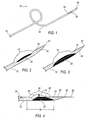
FIG. 1 is perspective elevated view of a catheter according to one embodiment; -
FIG. 2 is an exploded perspective view of a cavity ofFIG. 1 ; -
FIG. 3 is an exploded perspective view ofFIG. 1 showing one embodiment of a ramp; -
FIG. 4 is an exploded perspective view ofFIG. 1 showing a ramp, a laser delivery member, and a guidewire; -
FIG. 5 is a perspective elevated view of a first embodiment of a support structure; -
FIG. 6 is a top plan view ofFIG. 5 ; -
FIG. 7 is a side plan view ofFIG. 5 ; -
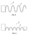
FIG. 8 is a top plan view of a second embodiment of a support structure; -
FIG. 9 is a side plan view ofFIG. 8 ; -
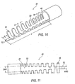
FIG. 10 is a perspective elevated view of a third embodiment of a support structure; -
FIG. 11 is a top plan view ofFIG. 10 ; -
FIG. 12 is a perspective elevated view of a fourth embodiment of a support structure; -
FIG. 13 is a perspective elevated view of a fifth embodiment of a support structure; -
FIG. 14 is a perspective elevated view of a sixth embodiment of a support structure; -
FIG. 15 is a top plan view of a seventh embodiment of a support structure; and -
FIG. 16 is a perspective elevated view ofFIG. 15 . - Referring now to the drawings, illustrative embodiments are shown in detail. Although the drawings represent some embodiments, the drawings are not necessarily to scale and certain features may be exaggerated to better illustrate and explain an innovative aspect of an embodiment. Further, the embodiments described herein are not intended to be exhaustive or otherwise limit or restrict the embodiments of the invention to the precise form and configuration shown in the drawings and disclosed in the following detailed description.
- Referring now to
FIGS. 1 - 4 , acatheter 10 is shown having anelongated housing 12. Theelongated housing 12 includes a central axis between a firstproximal end 14 and a firstdistal end 16. Acavity 18 is located proximate to the firstdistal end 16 ofelongated housing 12 having aramp 20 at an angle to the central axis of thehousing 12. The angle of theramp 20 may but need not be the same over the length of the ramp. In some preferred embodiments, without limiting the scope of the invention, the housing includes a taperingend 30 and aguide wire aperture 32 capable of accepting theguidewire 28. Alaser delivery member 22 comprising one or more optical fibers capable of transmitting light energy is disposed within achannel 26 of thehousing 12 having a second proximal end (not shown) and a seconddistal end 24 movable therein. In some embodiments, without limitation, thelaser delivery member 22 may be in mechanical communication with aguidewire 28 as further discussed below. - The
guidewire 28 is threaded through a needle (not shown) into the artery and the needle is removed. The guidewire is advanced to or near the treatment site and may be inserted at its distal end into or across the lesion to be treated, as desired. Theguidewire 28 serves as a tracking guide for thehousing 12 andlaser delivery member 22 to run on. Guidewires for such uses are known in the art and may comprise those with diameters between about 0.010 and 0.06 inches, with 0.014 and 0.018 inches diameter being typical sizes for artery applications. The guidewires may have bendable tips of coiled wire or plastic and a more rigid shaft of tapered ground stainless steel or other suitable material for push and torque transmission. Thehousing 12 andlaser delivery member 22 are introduced coaxially, either sequentially or simultaneously, onto theguidewire 28 and advanced to a target area as further discussed below. - In some embodiments, without limitation, the
housing 12 is introduced onto theguidewire 28 that has been inserted into the patient, and the housing is advanced to or near the treatment site such that portions of theguidewire 28 are disposed at least initially within theguide wire aperture 32, taperingend 30, andchannel 26 of the housing. Thelaser delivery member 22 is then introduced onto theguidewire 28 so disposed within thecatheter 10. Thelaser delivery member 22 is then advanced along theguidewire 28 such that thedistal end 24 of thelaser delivery member 22 becomes supported by theramp 20 and oriented within thecavity 18 at any angle between 1 degree and 90 degrees in relation to the central axis of thehousing 12, as desired by the user. Laser energy is then applied to the treatment site according to methods and protocols known to those of ordinary skill in the art. In some embodiments, without limiting the scope of the invention, in conjunction with the application of laser energy, the position of thelaser delivery member 22 may optionally be varied by the user by moving themember 22 proximally or distally in order to adjust the angle of disposition of itsdistal end 24. Optionally, the offset of the central axis of the tip of thelaser delivery member 22 from the central axis of thehousing 12 may be varied by adjusting the distance that thedelivery member 22 travels on theramp 20 while keeping the central axis of the tip substantially parallel to the central axis of thehousing 12. In addition, thecatheter 10 containing thelaser delivery member 22 may optionally be rotated along its central axis during the laser treatment and thereby apply laser energy to areas of the treatment site within the arc of the rotation. Optionally, theguidewire 28 may be withdrawn before application of laser energy and after thelaser delivery member 22 has been introduced via theguidewire 28 into thechannel 26 of thehousing 12. - The
elongated housing 12 is an elongated structure having a lumen orchannel 26 large enough to accommodate thelaser delivery member 22 andguidewire 28. Thechannel 26 extends the entire length of thehousing 12 from the firstproximal end 14 to the firstdistal end 16. Optionally, in some embodiments, thechannel 26 may extend only to theramp 20. Various control mechanisms including electrical, optical, and mechanical control mechanisms may be employed with thehousing 12 permitting the catheter to be specifically directed to a target area (not shown) within the blood vessel. One embodiment of the housing includes a taperingend 30 and aguide wire aperture 32 capable of accepting theguidewire 28. Thehousing 12 may be made from any rigid, semi-flexible, or flexible material including a combination thereof made from a material including metal, plastic, rubber, and the like. Round or flat metal ribbon wire may be embedded within the material, inserted through thecavity 18, or disposed at the firstdistal end 16 to add stability to thehousing 12 at the firstdistal end 16. The length of thehousing 12 may be varied as desired. Thehousing 12 may be one piece or have a plurality of sections including a support structure section at the firstdistal end 16 as discussed further below. Thedistal end 16 of thehousing 12 may include a non-traumatic polymer tip separate or integrated into thehousing 12. This allows the forces seen in bending to be dissipated throughout the structure, reducing stress risers that could cause failure. Thehousing 12 may also include at least one wire disposed within thechannel 26 to add robustness to thehousing 12. Thechannel 26 is in communication withcavity 18 andwire aperture 32. Thechannel 26 is open to the exterior of thehousing 12 through thecavity 18. - The
ramp 20 is disposed withincavity 18 and is configured to project thelaser delivery member 22 outwardly at various determinable angles. Optionally, theramp 20 is used to determine the offset of the central axis of the tip of thelaser delivery member 22 from the central axis of thehousing 20, while keeping the axes substantially parallel, by adjusting the extent to which thelaser delivery member 22 travels on theramp 20. In some embodiments without limitation, the disposition of thelaser delivery member 22 on theguidewire 28 maintains the offset tip substantially parallel to the central axis of thehousing 12. In some embodiments, without limitation, the angle of lateral deviation of theramp 20 from central axis of thehousing 12 will vary in range as desired from one (1) degree to ninety (90) degrees, more usually in the range from thirty (30) degrees to sixty-five (65) degrees. By employingramp 20 having different exit angles from the associatedchannel 26, different angles and/or offsets may be selected for treating a target area after thecatheter 10 has been located within a patient. In some embodiments, without limitation, theramp 20 may be adjustable, as one example only, by inflation of a balloon, and/or theramp 20 may be slidable to allow varying degrees of offset. - The
ramp 20 may be a built-up feature within thechannel 26 of thehousing 12 and may be located anywhere along the longitudinal length of thehousing 12, but preferably at or within about 3 cm from the firstdistal end 16 of thehousing 12. Theramp 20 may be formed or fused to the internal wall of thehousing 12 and made from metal, plastic, rubber, and the like. In one embodiment, the ramp length (RL) is generally 1 cm. However, the ramp length (RL) may also be varied. - The first
distal end 16 of thehousing 12 may be formed from plastic, metal, or any combination thereof. When metal is used, materials must be selected to provide appropriate flexibility without producing failure since thecavity 18 tends to reduce the structural integrity of some portions of thehousing 12. Thus, in some embodiments, the firstdistal end 16 comprises a shape memory alloy, as one example only, nickel-titanium alloy. In other embodiments, without limitation, the firstdistal end 16 may comprise a stent-like structure proximal, distal, within, or a combination of such proximate thecavity 18. The stent-like structure may be made from at least one of stainless steel, cobalt-chromium, nickel titanium, and the like. - An alternative embodiment of the
housing 12 comprises having at least one section at the firstdistal end 16. A first embodiment of a support structure issupport member 34 as shown inFIGS. 5-7 . Thesupport member 34 may be used to support the firstdistal end 16 while providing flexibility without producing failure. The firstdistal end 16 of thehousing 12 may otherwise experience limited torsional and bending strength of the area around thecavity 18 specifically traversing bends having a radius of about 0.75 inches. Thesupport member 34 assists in withstanding the torsional and bending forces when traversing bends of about 0.75 inches, while maintaining aspects of both integrity and functionality. In some embodiments, without limitation,support member 34 reinforces the area around thecavity 18 at the firstdistal end 16 withstruts 36 forming a stent-like pattern 38.Support member 34 is formed from metal, plastic, or combinations thereof, and is at least partially axially disposed around the wall of the firstdistal end 16 of thehousing 12. Thehousing 12 may be one longitudinal piece or have a plurality of sections including the support structure as described above disposed at the firstdistal end 16 of thehousing 12. Other embodiments of the support structure include a marker band proximate the firstdistal end 16 of thehousing 12 and radiopaque markers at various intervals along theramp 20 to demarcateacceptable ramp 20 positions for thecatheter 10. As one example only, a user may place a catheter at a first mark on the ramp to increase the offset for ablation to 1mm. A second mark might equal a 1.5 mm offset. This way the support structure may be used progressively, as one example only, as a progressive atherectomy tool. Additional embodiments having generally similar benefits may also be used, as further discussed below. - Referring to
FIGS. 8 and 9 , a second embodiment of a support structure is shown assecond support member 40 having a spring-like geometry 42. Thesupport member 40 may be used to support the firstdistal end 16 while providing flexibility without producing failure. Thesecond support member 40 acts as a backbone for the firstdistal end 16 of thehousing 12. The spring-like geometry 42 permits flexing without causing failure. The height H of the spring-like geometry 42 may be of any height but is preferably below the centerline of thesecond support member 40. Theramp 20 may be molded over the spring likegeometry 42 including having a top coat (not shown). - Referring to
FIGS. 10 and 11 , a third embodiment of a support structure is shown as athird support member 44. Thesupport member 44 may be used to support the firstdistal end 16 while providing flexibility without producing failure. Thethird support member 44 provides variable stiffness along the length of themember 44.Member 44 is the most rigid atrib 46 and most flexible atrib 48. This flexibility is accomplished by having the ribs increase in width W and distance D in addition to decreasing the side of abeam 50 as shown inFIG. 11 .Beam 50 tapers from a first wide beam width BW1 to a narrower beam width BW2. Atip 52 having a tip length TL disposed at the distalend support member 44 functions to provide support for the firstdistal end 16 of thehousing 12 while allowing additional flexibility. Theramp 20 may be molded over the spring-like geometry 42 including having a top coat (not shown). The support member length L may be varied depending on user requirements including varying the tip length TL. -
FIG. 12 shows a fourth embodiment of a support structure asfourth support member 54 disposed at the firstdistal end 16 of thehousing 12. Thesupport member 54 may be used to support the firstdistal end 16 while providing flexibility without producing failure.Support member 54 includes arigid body 56 and a variablyrigid base 58 extending from thebody 56.Body 56 includes anaperture 57 in communication withchannel 26. The base 58 may be elastomeric having the greatest flexibility atdistal end 60. Theramp 20 may be molded over the base 58 including having a top coat (not shown). The support member base length BL may be varied according to user requirements. -
FIG. 13 shows a fifth embodiment of a support structure asfifth support member 62. Thesupport member 62 includes arigid body 64 having a flexibletapered nose portion 66. At least thenose portion 66 may be comprised of elastomeric material, as one example only, Rebax 55D available from Arkema. Thebody 64 is configured to communicate with the firstdistal end 16 of thehousing 12. Anaperture 68 is disposed withinbody 64 in communication withchannel 26 of thehousing 12 and is configured to accommodate both thelaser delivery member 22 andguidewire 28.Aperture 68 is also in communication with thenose widow 69. Thenose window 69 of thenose portion 66 includes anose ramp 70 configured to project thelaser delivery member 22 outwardly at various predetermined angles. Optionally, theramp 20 is used to determine the offset of the central axis of the tip of thelaser delivery member 22 from the central axis of thehousing 20, while keeping the axes substantially parallel, by adjusting the extent to which thelaser delivery member 22 travels on theramp 20. In some embodiments without limitation, the disposition of thelaser delivery member 22 on theguidewire 28 maintains the offset tip substantially parallel to the central axis of thehousing 12. Usually, the angle of lateral deviation of theramp 20 from thehousing 12 will vary in range as desired from one (1) degree to ninety (90) degrees, more usually in the range from thirty (30) degrees to sixty-five (65) degrees. The nose portion also includes anose channel 72 and anose guidewire aperture 74. Theguidewire 28 disposed within and in mechanical communication thelaser delivery member 22 extends outwardly from the seconddistal end 24 of thelaser delivery member 22 and is guided through thenose channel 72 and extending out theguidewire aperture 74. Both thenose channel 72 andguidewire aperture 74 provide securement for theguidewire 28 so that theguidewire 28 may properly bias the seconddistal end 24 of thelaser delivery member 22 generally inwardly toward the central axis of thebody 64. -
FIG. 14 shows a sixth embodiment of a support structure assixth support member 80. Thesupport member 80 may be used to support the firstdistal end 16 while providing flexibility without producing failure.Support member 80 includes arigid body 82 and at least two variablyrigid legs 84 extending from thebody 82.Body 82 includes anaperture 86 in communication with thechannel 26. Thebody 82 may be elastomeric having the greatest flexibility atdistal end 88. Thelegs 84 may be of any shape extending from thebody 82. Theramp 20 may be molded over thelegs 84 including having a top coat (not shown). The support member leg length LL may be varied depending on user requirements. -
FIGS. 15 and 16 show a seventh embodiment of a support structure asseventh support member 90. Thesupport member 90 may be used to support the firstdistal end 16 while providing flexibility without producing failure. The firstdistal end 16 of thehousing 12 may otherwise experience limited torsional and bending strength of the area around thecavity 18 specifically traversing bends having a radius of about 0.75 inches. Thesupport member 90 assists in withstanding the torsional and bending forces when traversing bends of about 0.75 inches while maintaining both integrity and functionality.Support member 90 reinforces the area around thecavity 18 at the firstdistal end 16 with abraid 92 forming a stent-like pattern 94.Support member 90 is formed from metal or plastic and is at least partially axially disposed around the wall of the firstdistal end 16 of thehousing 12. Thehousing 12 may be one longitudinal piece or have a plurality of sections including the support structure as described above disposed at the firstdistal end 16 of thehousing 12.Support member 90 includes arigid body 92 and a variablyrigid base 94 forming the stent-like pattern 94 extending from thebody 92.Body 92 includes anaperture 96 in communication withchannel 26. The base 94 may be elastomeric having the greatest flexibility atdistal end 98. Atip 100 having a tip length TL disposed at the distalend support member 90 functions to provide support for the firstdistal end 16 of thehousing 12 while allowing additional flexibility. Theramp 20 may be molded over the base 94 including having a top coat (not shown). The support member stent-like length SL may be varied depending on user requirements. - In operation, once the
guidewire 28 is in place, or as it is being positioned, thehousing 12 is inserted. Thishousing 12 has acentral channel 26, which may include thelaser delivery member 22 andguidewire 28. Thehousing 12 and thelaser delivery member 22 are advanced through the guidewire into the desired target area. Therefore, theguidewire 28 is in mechanical communication with both thelaser delivery member 22 and theelongated housing 12. However, thehousing 12 may be advanced prior to inserting thelaser delivery member 22. As thelaser delivery member 22 approaches theramp 20, it is biased in an outwardly direction through thecavity 18. The further thelaser delivery member 22 is advanced, the more it projects outwardly from thecavity 18 at the firstdistal end 16 of thehousing 12. In some embodiments, without limitation, theguidewire 28 disposed within thelaser delivery member 22 biases the seconddistal end 24 of thelaser delivery member 22 inwardly providing a travel path and forcing the seconddistal end 24 to face forward along theguidewire 28 and generally parallel to the centerline of thehousing 12. Otherwise, the seconddistal end 24 of thelaser delivery member 22 would continue along theramp 20 further projecting away from the centerline of thehousing 12 and would not be "attacking" the target area in front of thecatheter 10 as desired. - The preceding description has been presented only to illustrate and describe exemplary embodiments of the systems of the present invention. It is not intended to be exhaustive or to limit the invention to any precise form disclosed. It will be understood by those skilled in the art that various changes may be made and equivalents may be substituted for elements thereof without departing from the scope of the invention. In addition, many modifications may be made to adapt a particular situation or material to the teachings of the invention without departing from the essential scope. Therefore, it is intended that the invention not be limited to the particular embodiment disclosed as the best mode contemplated for carrying out this invention, but that the invention will include all embodiments falling within the scope of the claims. The invention may be practiced otherwise than is specifically explained and illustrated without departing from its scope.
Claims (25)
- A catheter (10) comprising:an elongated housing (12) having a central axis between a first proximal end (14) and a first distal end (16), said housing (12) having a channel (26) disposed between said first proximal end (14) and said first distal end (16);a laser delivery member (22) having a second proximal end and a second distal end (24) and comprising at least one optical fiber, said laser delivery member being at least partially disposed within said channel (26) and movable therein;a cavity being disposed proximate said first distal end (16) of said elongated housing (12) and in communication with said channel (26); anda ramp (20) disposed within the cavity at an angle to said central axis and proximate said first distal end (16) of said elongated housing (12), said ramp (20) being in communication with said channel (26) and adapted to move said second distal end (24) of said laser delivery member (22) outwardly from said central axis of said elongated member;characterised in that the catheter further includes:a guidewire (28) in mechanical communication with both said laser delivery member and said elongated housing (12), said guidewire (28) being adapted to bias said second distal end (24) of said laser delivery member (22) generally inwardly toward said central axis.
- The catheter of claim 1, wherein said elongated housing (12) is formed from a flexible material.
- The catheter of claim 2, wherein said flexible material provides said housing (12) the ability to travel contralaterally within the vasculature of a mammal.
- The catheter of claim 3, wherein said vasculature comprises the iliac bifurcation.
- The catheter of claim 1, wherein said elongated housing (12) includes a braided pattern (38) along at least a portion of said housing (12).
- The catheter of claim 1, wherein said elongated housing (12) includes a braided pattern (38) along at least one half of a length of said housing (12).
- The catheter of claim 1, wherein said elongated housing (12) includes a round or flat metal ribbon wire embedded within said housing (12).
- The catheter of claim 1, wherein said elongated housing (12) includes a wire braid disposed proximate said first distal end (16).
- The catheter of claim 1, wherein said elongated housing (12) includes at least one wire disposed within said housing (12).
- The catheter of claim 1, wherein said elongated housing (12) includes a polymer tip disposed at said first distal end (16) separate from or integrated into said housing (12).
- the catheter of claim 1, wherein said elongated housing (12) includes a stent-like structure disposed proximate at least one of said distal end (16), said proximal end (14), and therebetween.
- The catheter of claim 1, wherein said stent-like structure is formed from one of stainless steel, cobalt-chromium, and nickel titanium or any combination thereof.
- The catheter of claim 1, wherein said ramp (20) is inflatable.
- The catheter of claim 1, wherein said ramp (20) is formed into an internal wall of said housing (12).
- The catheter of claim 1, wherein said ramp (20) is formed from one of a metal, plastic, and rubber.
- The catheter of claim 1, wherein said ramp (20) includes a marker band disposed along said ramp (20).
- The catheter of claim 1, wherein said ramp (20) includes at least one radiopaque marker disposed at a predetermined location along a longitudinal length of said ramp (20).
- The catheter of claim 1, further comprising a support structure (34, 40, 44, 56, 62, 80, 90) disposed at said first distal end (16) of said housing (12).
- The catheter of claim 18, wherein said support structure is integrated with said housing (12) proximate said first distal end (16).
- The catheter of claim 18, wherein said support structure (56) includes an aperture (57) in communication with said channel (26).
- The catheter of claim 18, wherein said support structure includes a stent-like or coiled form.
- The catheter of claim 18, wherein said support structure is progressively more flexible from a support structure proximal end to a support structure distal end.
- The catheter of claim 18, wherein said support structure includes a surface comprising at least a portion having a stent-like pattern.
- The catheter of claim 18, wherein said support structure includes said ramp (20) molded into a surface of said support structure.
- The catheter of claim 18, wherein said support structure supports said first distal end (16) of said housing (12).
Priority Applications (1)
| Application Number | Priority Date | Filing Date | Title |
|---|---|---|---|
| EP08010688A EP1974684A3 (en) | 2004-09-17 | 2005-09-16 | Apparatus and methods for directional delivery of laser energy |
Applications Claiming Priority (2)
| Application Number | Priority Date | Filing Date | Title |
|---|---|---|---|
| US61119104P | 2004-09-17 | 2004-09-17 | |
| PCT/US2005/033029 WO2006033989A2 (en) | 2004-09-17 | 2005-09-16 | Apparatus and methods for directional delivery of laser energy |
Related Child Applications (1)
| Application Number | Title | Priority Date | Filing Date |
|---|---|---|---|
| EP08010688A Division EP1974684A3 (en) | 2004-09-17 | 2005-09-16 | Apparatus and methods for directional delivery of laser energy |
Publications (3)
| Publication Number | Publication Date |
|---|---|
| EP1804704A2 EP1804704A2 (en) | 2007-07-11 |
| EP1804704A4 EP1804704A4 (en) | 2008-04-09 |
| EP1804704B1 true EP1804704B1 (en) | 2009-02-18 |
Family
ID=36090503
Family Applications (2)
| Application Number | Title | Priority Date | Filing Date |
|---|---|---|---|
| EP05796879A Active EP1804704B1 (en) | 2004-09-17 | 2005-09-16 | Apparatus for directional delivery of laser energy |
| EP08010688A Withdrawn EP1974684A3 (en) | 2004-09-17 | 2005-09-16 | Apparatus and methods for directional delivery of laser energy |
Family Applications After (1)
| Application Number | Title | Priority Date | Filing Date |
|---|---|---|---|
| EP08010688A Withdrawn EP1974684A3 (en) | 2004-09-17 | 2005-09-16 | Apparatus and methods for directional delivery of laser energy |
Country Status (6)
| Country | Link |
|---|---|
| US (2) | US7572254B2 (en) |
| EP (2) | EP1804704B1 (en) |
| JP (1) | JP4460606B2 (en) |
| AT (1) | ATE422851T1 (en) |
| DE (1) | DE602005012853D1 (en) |
| WO (1) | WO2006033989A2 (en) |
Families Citing this family (42)
| Publication number | Priority date | Publication date | Assignee | Title |
|---|---|---|---|---|
| WO1998038936A1 (en) | 1997-03-04 | 1998-09-11 | Vnus Medical Technologies, Inc. | Method and apparatus for treating venous insufficiency using directionally applied energy |
| US8545488B2 (en) | 2004-09-17 | 2013-10-01 | The Spectranetics Corporation | Cardiovascular imaging system |
| WO2006033989A2 (en) * | 2004-09-17 | 2006-03-30 | The Spectranetics Corporation | Apparatus and methods for directional delivery of laser energy |
| US8628519B2 (en) * | 2004-09-17 | 2014-01-14 | The Spectranetics Corporation | Rapid exchange bias laser catheter design |
| WO2007089714A2 (en) * | 2006-01-27 | 2007-08-09 | The Spectranetics Corporation | Interventional devices and methods for laser ablation |
| AU2008245600B2 (en) | 2007-04-27 | 2013-07-04 | Covidien Lp | Systems and methods for treating hollow anatomical structures |
| US9770297B2 (en) * | 2008-06-04 | 2017-09-26 | Covidien Lp | Energy devices and methods for treating hollow anatomical structures |
| US20100114081A1 (en) * | 2008-11-05 | 2010-05-06 | Spectranetics | Biasing laser catheter: monorail design |
| US9408665B2 (en) * | 2008-12-12 | 2016-08-09 | The Spectranetics Corporation | Offset catheter |
| US8702773B2 (en) * | 2008-12-17 | 2014-04-22 | The Spectranetics Corporation | Eccentric balloon laser catheter |
| EP2677961A4 (en) | 2011-02-24 | 2014-10-29 | Eximo Medical Ltd | Hybrid catheter for vascular intervention |
| US8663190B2 (en) | 2011-04-22 | 2014-03-04 | Ablative Solutions, Inc. | Expandable catheter system for peri-ostial injection and muscle and nerve fiber ablation |
| US9237925B2 (en) | 2011-04-22 | 2016-01-19 | Ablative Solutions, Inc. | Expandable catheter system for peri-ostial injection and muscle and nerve fiber ablation |
| US20130053792A1 (en) | 2011-08-24 | 2013-02-28 | Ablative Solutions, Inc. | Expandable catheter system for vessel wall injection and muscle and nerve fiber ablation |
| EP2765944B1 (en) | 2011-10-14 | 2018-09-05 | RA Medical Systems | Small flexible liquid core catheter for laser ablation in body lumens |
| US10610294B2 (en) | 2012-04-22 | 2020-04-07 | Newuro, B.V. | Devices and methods for transurethral bladder partitioning |
| US9883906B2 (en) | 2012-04-22 | 2018-02-06 | Newuro, B.V. | Bladder tissue modification for overactive bladder disorders |
| WO2013160772A2 (en) | 2012-04-22 | 2013-10-31 | Omry Ben-Ezra | Bladder tissue modification for overactive bladder disorders |
| US10945787B2 (en) | 2012-10-29 | 2021-03-16 | Ablative Solutions, Inc. | Peri-vascular tissue ablation catheters |
| US9623211B2 (en) | 2013-03-13 | 2017-04-18 | The Spectranetics Corporation | Catheter movement control |
| US9320530B2 (en) | 2013-03-13 | 2016-04-26 | The Spectranetics Corporation | Assisted cutting balloon |
| US10758308B2 (en) | 2013-03-14 | 2020-09-01 | The Spectranetics Corporation | Controller to select optical channel parameters in a catheter |
| US11642169B2 (en) | 2013-03-14 | 2023-05-09 | The Spectranetics Corporation | Smart multiplexed medical laser system |
| US9757200B2 (en) | 2013-03-14 | 2017-09-12 | The Spectranetics Corporation | Intelligent catheter |
| US9962527B2 (en) | 2013-10-16 | 2018-05-08 | Ra Medical Systems, Inc. | Methods and devices for treatment of stenosis of arteriovenous fistula shunts |
| US9931046B2 (en) | 2013-10-25 | 2018-04-03 | Ablative Solutions, Inc. | Intravascular catheter with peri-vascular nerve activity sensors |
| CN106061420B (en) * | 2013-10-25 | 2021-12-07 | 消融系统有限公司 | Intravascular catheter with perivascular nerve activity sensor |
| US9949652B2 (en) | 2013-10-25 | 2018-04-24 | Ablative Solutions, Inc. | Apparatus for effective ablation and nerve sensing associated with denervation |
| CN106794043B (en) | 2014-05-18 | 2020-03-13 | 爱克斯莫医疗有限公司 | System for tissue ablation using pulsed laser |
| US10987168B2 (en) | 2014-05-29 | 2021-04-27 | Spectranetics Llc | System and method for coordinated laser delivery and imaging |
| WO2016069754A1 (en) | 2014-10-29 | 2016-05-06 | The Spectranetics Corporation | Laser energy delivery devices including laser transmission detection systems and methods |
| US10492863B2 (en) | 2014-10-29 | 2019-12-03 | The Spectranetics Corporation | Laser energy delivery devices including laser transmission detection systems and methods |
| US10646118B2 (en) | 2014-12-30 | 2020-05-12 | Regents Of The University Of Minnesota | Laser catheter with use of reflected light to determine material type in vascular system |
| US10646274B2 (en) | 2014-12-30 | 2020-05-12 | Regents Of The University Of Minnesota | Laser catheter with use of reflected light and force indication to determine material type in vascular system |
| US10646275B2 (en) | 2014-12-30 | 2020-05-12 | Regents Of The University Of Minnesota | Laser catheter with use of determined material type in vascular system in ablation of material |
| USD775728S1 (en) | 2015-07-02 | 2017-01-03 | The Spectranetics Corporation | Medical device handle |
| US10499892B2 (en) | 2015-08-11 | 2019-12-10 | The Spectranetics Corporation | Temporary occlusion balloon devices and methods for preventing blood flow through a vascular perforation |
| US10449336B2 (en) | 2015-08-11 | 2019-10-22 | The Spectranetics Corporation | Temporary occlusions balloon devices and methods for preventing blood flow through a vascular perforation |
| US10555772B2 (en) | 2015-11-23 | 2020-02-11 | Ra Medical Systems, Inc. | Laser ablation catheters having expanded distal tip windows for efficient tissue ablation |
| WO2017191644A1 (en) | 2016-05-05 | 2017-11-09 | Eximo Medical Ltd | Apparatus and methods for resecting and/or ablating an undesired tissue |
| JP2019166289A (en) | 2018-03-22 | 2019-10-03 | ラ メディカル システムズ, インコーポレイテッド | Liquid filled ablation catheter with overjacket |
| WO2021255013A1 (en) | 2020-06-18 | 2021-12-23 | Koninklijke Philips N.V. | Atherectomy guidance through photoacoustic signal analysis |
Family Cites Families (73)
| Publication number | Priority date | Publication date | Assignee | Title |
|---|---|---|---|---|
| US4053845A (en) * | 1967-03-06 | 1977-10-11 | Gordon Gould | Optically pumped laser amplifiers |
| US4848336A (en) * | 1981-12-11 | 1989-07-18 | Fox Kenneth R | Apparatus for laser treatment of body lumens |
| US5041108A (en) * | 1981-12-11 | 1991-08-20 | Pillco Limited Partnership | Method for laser treatment of body lumens |
| US4784132A (en) * | 1983-03-25 | 1988-11-15 | Fox Kenneth R | Method of and apparatus for laser treatment of body lumens |
| US4686979A (en) * | 1984-01-09 | 1987-08-18 | The United States Of America As Represented By The United States Department Of Energy | Excimer laser phototherapy for the dissolution of abnormal growth |
| US4747405A (en) * | 1984-03-01 | 1988-05-31 | Vaser, Inc. | Angioplasty catheter |
| US4627436A (en) * | 1984-03-01 | 1986-12-09 | Innoventions Biomedical Inc. | Angioplasty catheter and method for use thereof |
| US4830460A (en) * | 1987-05-19 | 1989-05-16 | Advanced Interventional Systems, Inc. | Guidance system and method for delivery system for high-energy pulsed ultraviolet laser light |
| US4732448A (en) * | 1984-12-07 | 1988-03-22 | Advanced Interventional Systems, Inc. | Delivery system for high-energy pulsed ultraviolet laser light |
| US5989243A (en) * | 1984-12-07 | 1999-11-23 | Advanced Interventional Systems, Inc. | Excimer laser angioplasty system |
| US5188632A (en) * | 1984-12-07 | 1993-02-23 | Advanced Interventional Systems, Inc. | Guidance and delivery system for high-energy pulsed laser light |
| US4641912A (en) * | 1984-12-07 | 1987-02-10 | Tsvi Goldenberg | Excimer laser delivery system, angioscope and angioplasty system incorporating the delivery system and angioscope |
| US5470330A (en) * | 1984-12-07 | 1995-11-28 | Advanced Interventional Systems, Inc. | Guidance and delivery system for high-energy pulsed laser light |
| US4799754A (en) * | 1985-09-25 | 1989-01-24 | Advanced Interventional Systems, Inc. | Delivery system for high-energy pulsed ultraviolet laser light |
| GB2175505B (en) * | 1985-05-22 | 1989-10-25 | Bard Inc C R | Wire guided laser catheter |
| US5350395A (en) * | 1986-04-15 | 1994-09-27 | Yock Paul G | Angioplasty apparatus facilitating rapid exchanges |
| US5040548A (en) * | 1989-06-01 | 1991-08-20 | Yock Paul G | Angioplasty mehtod |
| US4807620A (en) * | 1987-05-22 | 1989-02-28 | Advanced Interventional Systems, Inc. | Apparatus for thermal angioplasty |
| US4844062A (en) * | 1987-10-23 | 1989-07-04 | Spectranetics Corporation | Rotating fiberoptic laser catheter assembly with eccentric lumen |
| US4788975B1 (en) * | 1987-11-05 | 1999-03-02 | Trimedyne Inc | Control system and method for improved laser angioplasty |
| US4924863A (en) * | 1988-05-04 | 1990-05-15 | Mmtc, Inc. | Angioplastic method for removing plaque from a vas |
| US6066130A (en) * | 1988-10-24 | 2000-05-23 | The General Hospital Corporation | Delivering laser energy |
| DE69027678T2 (en) * | 1989-05-03 | 1997-02-20 | Medical Technologies Inc Enter | INSTRUMENT FOR INTRALUMINAL RELIEF OF STENOSES |
| EP0436700B1 (en) * | 1989-07-31 | 1997-10-29 | BARKEN, Israel | Ultrasound-laser surgery apparatus |
| US5016964A (en) * | 1989-10-04 | 1991-05-21 | Spectranetics Corporation | Optical fiber coupler with linear input |
| US5024234A (en) * | 1989-10-17 | 1991-06-18 | Cardiovascular Imaging Systems, Inc. | Ultrasonic imaging catheter with guidewire channel |
| US5558093A (en) * | 1990-05-18 | 1996-09-24 | Cardiovascular Imaging Systems, Inc. | Guidewire with imaging capability |
| US5304171A (en) * | 1990-10-18 | 1994-04-19 | Gregory Kenton W | Catheter devices and methods for delivering |
| US5425355A (en) * | 1991-01-28 | 1995-06-20 | Laserscope | Energy discharging surgical probe and surgical process having distal energy application without concomitant proximal movement |
| US5250045A (en) * | 1991-06-11 | 1993-10-05 | The Spectranetics Corporation | Optical fiber catheter with spaced optical fiber |
| US5217454A (en) * | 1991-08-01 | 1993-06-08 | Angiolaz, Incorporated | Laser delivery catheter |
| US5267341A (en) * | 1991-10-30 | 1993-11-30 | Baxter International Inc. | Fluid catheter with aqueous fluid core and method of use |
| US5263953A (en) * | 1991-12-31 | 1993-11-23 | Spine-Tech, Inc. | Apparatus and system for fusing bone joints |
| US5318032A (en) * | 1992-02-05 | 1994-06-07 | Devices For Vascular Intervention | Guiding catheter having soft tip |
| JPH06511181A (en) * | 1992-03-18 | 1994-12-15 | ザ・スペクトラネティックス・コーポレーション | Fiber optic catheter with flexible tip |
| US5352197A (en) * | 1992-03-18 | 1994-10-04 | The Spectranetics Corporation | Turn limiter for a catheter with twistable tip |
| ATE182273T1 (en) * | 1992-08-18 | 1999-08-15 | Spectranetics Corp | GUIDE WIRE WITH FIBER OPTICS |
| WO1994004083A1 (en) * | 1992-08-26 | 1994-03-03 | Advanced Interventional Systems | Optical catheter with stranded fibers |
| US5350377A (en) * | 1992-10-26 | 1994-09-27 | Ultrasonic Sensing & Monitoring Systems, Inc. | Medical catheter using optical fibers that transmit both laser energy and ultrasonic imaging signals |
| US5315747A (en) * | 1992-10-30 | 1994-05-31 | Pameda N.V. | Method of preparing a balloon dilatation catheter |
| US5350375A (en) * | 1993-03-15 | 1994-09-27 | Yale University | Methods for laser induced fluorescence intensity feedback control during laser angioplasty |
| US5722972A (en) * | 1993-08-12 | 1998-03-03 | Power; John A. | Method and apparatus for ablation of atherosclerotic blockage |
| US5456680A (en) * | 1993-09-14 | 1995-10-10 | Spectranetics Corp | Fiber optic catheter with shortened guide wire lumen |
| US5429617A (en) * | 1993-12-13 | 1995-07-04 | The Spectranetics Corporation | Radiopaque tip marker for alignment of a catheter within a body |
| US5484433A (en) * | 1993-12-30 | 1996-01-16 | The Spectranetics Corporation | Tissue ablating device having a deflectable ablation area and method of using same |
| US5440664A (en) * | 1994-01-13 | 1995-08-08 | Rutgers, The State University Of New Jersey | Coherent, flexible, coated-bore hollow-fiber waveguide |
| US5792118A (en) * | 1994-03-07 | 1998-08-11 | Kurth; Paul A. | Permanent catheter with an exterior balloon valve and method of using the same |
| WO1995029737A1 (en) * | 1994-05-03 | 1995-11-09 | Board Of Regents, The University Of Texas System | Apparatus and method for noninvasive doppler ultrasound-guided real-time control of tissue damage in thermal therapy |
| US5573531A (en) * | 1994-06-20 | 1996-11-12 | Gregory; Kenton W. | Fluid core laser angioscope |
| US5623940A (en) * | 1994-08-02 | 1997-04-29 | S.L.T. Japan Co., Ltd. | Catheter apparatus with a sensor |
| US5571151A (en) * | 1994-10-25 | 1996-11-05 | Gregory; Kenton W. | Method for contemporaneous application of laser energy and localized pharmacologic therapy |
| US5817144A (en) * | 1994-10-25 | 1998-10-06 | Latis, Inc. | Method for contemporaneous application OF laser energy and localized pharmacologic therapy |
| US5891133A (en) * | 1996-03-29 | 1999-04-06 | Eclipse Surgical Technologies, Inc. | Apparatus for laser-assisted intra-coronary transmyocardial revascularization and other applications |
| US5824026A (en) * | 1996-06-12 | 1998-10-20 | The Spectranetics Corporation | Catheter for delivery of electric energy and a process for manufacturing same |
| US5755714A (en) * | 1996-09-17 | 1998-05-26 | Eclipse Surgical Technologies, Inc. | Shaped catheter for transmyocardial revascularization |
| EP0984727A4 (en) * | 1996-11-08 | 2000-05-24 | Thomas J Fogarty | Transvascular tmr device and method |
| US6117128A (en) * | 1997-04-30 | 2000-09-12 | Kenton W. Gregory | Energy delivery catheter and method for the use thereof |
| US6056743A (en) * | 1997-11-04 | 2000-05-02 | Scimed Life Systems, Inc. | Percutaneous myocardial revascularization device and method |
| US5976124A (en) * | 1998-01-05 | 1999-11-02 | Spectranetics Corporation | Phototherapy device and method |
| US6290668B1 (en) * | 1998-04-30 | 2001-09-18 | Kenton W. Gregory | Light delivery catheter and methods for the use thereof |
| US6022342A (en) * | 1998-06-02 | 2000-02-08 | Mukherjee; Dipankar | Catheter introducer for antegrade and retrograde medical procedures |
| US6447504B1 (en) * | 1998-07-02 | 2002-09-10 | Biosense, Inc. | System for treatment of heart tissue using viability map |
| US6287297B1 (en) * | 1999-03-05 | 2001-09-11 | Plc Medical Systems, Inc. | Energy delivery system and method for performing myocardial revascular |
| US6726807B1 (en) * | 1999-08-26 | 2004-04-27 | G.R. International, Inc. (A Washington Corporation) | Multi-phase calcium silicate hydrates, methods for their preparation, and improved paper and pigment products produced therewith |
| US6458098B1 (en) * | 2000-03-17 | 2002-10-01 | Nozomu Kanesaka | Vascular therapy device |
| WO2002045598A2 (en) * | 2000-12-05 | 2002-06-13 | Lumend, Inc. | Catheter system for vascular re-entry from a sub-intimal space |
| US6517531B2 (en) * | 2001-04-27 | 2003-02-11 | Scimed Life Systems, Inc. | Medical suction device |
| US6743208B1 (en) * | 2003-06-19 | 2004-06-01 | Medtronic Vascular, Inc | Occlusion balloon catheter with distal valve |
| US20050149176A1 (en) * | 2003-12-29 | 2005-07-07 | Scimed Life Systems, Inc. | Selectively light curable support members for medical devices |
| DE102004008366B3 (en) * | 2004-02-20 | 2005-09-15 | Siemens Ag | Apparatus for performing laser angioplasty with OCT monitoring |
| WO2006033989A2 (en) * | 2004-09-17 | 2006-03-30 | The Spectranetics Corporation | Apparatus and methods for directional delivery of laser energy |
| US8628519B2 (en) * | 2004-09-17 | 2014-01-14 | The Spectranetics Corporation | Rapid exchange bias laser catheter design |
| US20080108867A1 (en) * | 2005-12-22 | 2008-05-08 | Gan Zhou | Devices and Methods for Ultrasonic Imaging and Ablation |
-
2005
- 2005-09-16 WO PCT/US2005/033029 patent/WO2006033989A2/en active Search and Examination
- 2005-09-16 DE DE602005012853T patent/DE602005012853D1/de active Active
- 2005-09-16 EP EP05796879A patent/EP1804704B1/en active Active
- 2005-09-16 AT AT05796879T patent/ATE422851T1/en not_active IP Right Cessation
- 2005-09-16 EP EP08010688A patent/EP1974684A3/en not_active Withdrawn
- 2005-09-16 US US11/228,845 patent/US7572254B2/en active Active
- 2005-09-16 JP JP2007532474A patent/JP4460606B2/en active Active
-
2009
- 2009-03-18 US US12/406,807 patent/US7846153B2/en active Active
Also Published As
| Publication number | Publication date |
|---|---|
| EP1804704A4 (en) | 2008-04-09 |
| DE602005012853D1 (en) | 2009-04-02 |
| EP1974684A3 (en) | 2009-03-18 |
| JP2008513124A (en) | 2008-05-01 |
| ATE422851T1 (en) | 2009-03-15 |
| WO2006033989A2 (en) | 2006-03-30 |
| US7572254B2 (en) | 2009-08-11 |
| US20090198221A1 (en) | 2009-08-06 |
| WO2006033989A3 (en) | 2007-01-11 |
| US20060167442A1 (en) | 2006-07-27 |
| US7846153B2 (en) | 2010-12-07 |
| EP1804704A2 (en) | 2007-07-11 |
| JP4460606B2 (en) | 2010-05-12 |
| EP1974684A2 (en) | 2008-10-01 |
Similar Documents
| Publication | Publication Date | Title |
|---|---|---|
| EP1804704B1 (en) | Apparatus for directional delivery of laser energy | |
| US10111709B2 (en) | Rapid exchange bias laser catheter design | |
| US10987167B2 (en) | Biasing laser catheter: monorail design | |
| CN108025159B (en) | Occlusion bypass device with re-entry needle and stabilizer tube | |
| US10130385B2 (en) | Method and apparatus for placing a catheter within a vasculature | |
| US20080249515A1 (en) | Interventional Devices and Methods For Laser Ablation | |
| JP3467268B2 (en) | Fiber optic laser catheter | |
| US5722972A (en) | Method and apparatus for ablation of atherosclerotic blockage | |
| US9931166B2 (en) | Offset catheter | |
| US8377084B1 (en) | Method of using a catheter for traversing total occlusions | |
| US6506178B1 (en) | Apparatus and method for crossing a position along a tubular body structure | |
| US20110301502A1 (en) | In-vessel positioning device | |
| JP6537200B2 (en) | Occlusal bypass device and method with variable flexibility for bypassing an intravascular occlusion | |
| US20090005755A1 (en) | Guide wire control catheter for crossing occlusions and related methods of use | |
| US20050209559A1 (en) | Apparatus and methods for the treatment of chronic total occlusions | |
| JPH03158146A (en) | Acelectomy device and its method | |
| EP1853204B1 (en) | Stent delivery and guidewire guidance system with multiple guidewires | |
| WO2021237064A1 (en) | Pre-shaped medical devices | |
| US20080319386A1 (en) | Forwardly directable fluid jet crossing catheter | |
| JP6820611B2 (en) | Double concentric guide wire | |
| US20110202038A1 (en) | Guidewire positioning device | |
| US10820942B2 (en) | Internal rail system for laser catheter | |
| US20180185094A1 (en) | Rotating and sliding sleeve for handle portion of laser catheter | |
| JP2023534102A (en) | Scoring balloon catheter with enhanced pushability and maneuverability |
Legal Events
| Date | Code | Title | Description |
|---|---|---|---|
| PUAI | Public reference made under article 153(3) epc to a published international application that has entered the european phase |
Free format text: ORIGINAL CODE: 0009012 |
|
| 17P | Request for examination filed |
Effective date: 20070410 |
|
| AK | Designated contracting states |
Kind code of ref document: A2 Designated state(s): AT BE BG CH CY CZ DE DK EE ES FI FR GB GR HU IE IS IT LI LT LU LV MC NL PL PT RO SE SI SK TR |
|
| AX | Request for extension of the european patent |
Extension state: AL BA HR MK YU |
|
| DAX | Request for extension of the european patent (deleted) | ||
| A4 | Supplementary search report drawn up and despatched |
Effective date: 20080306 |
|
| RTI1 | Title (correction) |
Free format text: APPARATUS FOR DIRECTIONAL DELIVERY OF LASER ENERGY |
|
| RIC1 | Information provided on ipc code assigned before grant |
Ipc: A61B 18/24 20060101AFI20080703BHEP |
|
| GRAP | Despatch of communication of intention to grant a patent |
Free format text: ORIGINAL CODE: EPIDOSNIGR1 |
|
| GRAS | Grant fee paid |
Free format text: ORIGINAL CODE: EPIDOSNIGR3 |
|
| GRAA | (expected) grant |
Free format text: ORIGINAL CODE: 0009210 |
|
| AK | Designated contracting states |
Kind code of ref document: B1 Designated state(s): AT BE BG CH CY CZ DE DK EE ES FI FR GB GR HU IE IS IT LI LT LU LV MC NL PL PT RO SE SI SK TR |
|
| REG | Reference to a national code |
Ref country code: GB Ref legal event code: FG4D |
|
| REG | Reference to a national code |
Ref country code: CH Ref legal event code: EP |
|
| REG | Reference to a national code |
Ref country code: IE Ref legal event code: FG4D |
|
| REF | Corresponds to: |
Ref document number: 602005012853 Country of ref document: DE Date of ref document: 20090402 Kind code of ref document: P |
|
| PG25 | Lapsed in a contracting state [announced via postgrant information from national office to epo] |
Ref country code: SI Free format text: LAPSE BECAUSE OF FAILURE TO SUBMIT A TRANSLATION OF THE DESCRIPTION OR TO PAY THE FEE WITHIN THE PRESCRIBED TIME-LIMIT Effective date: 20090218 Ref country code: FI Free format text: LAPSE BECAUSE OF FAILURE TO SUBMIT A TRANSLATION OF THE DESCRIPTION OR TO PAY THE FEE WITHIN THE PRESCRIBED TIME-LIMIT Effective date: 20090218 Ref country code: ES Free format text: LAPSE BECAUSE OF FAILURE TO SUBMIT A TRANSLATION OF THE DESCRIPTION OR TO PAY THE FEE WITHIN THE PRESCRIBED TIME-LIMIT Effective date: 20090529 Ref country code: LT Free format text: LAPSE BECAUSE OF FAILURE TO SUBMIT A TRANSLATION OF THE DESCRIPTION OR TO PAY THE FEE WITHIN THE PRESCRIBED TIME-LIMIT Effective date: 20090218 Ref country code: NL Free format text: LAPSE BECAUSE OF FAILURE TO SUBMIT A TRANSLATION OF THE DESCRIPTION OR TO PAY THE FEE WITHIN THE PRESCRIBED TIME-LIMIT Effective date: 20090218 |
|
| NLV1 | Nl: lapsed or annulled due to failure to fulfill the requirements of art. 29p and 29m of the patents act | ||
| PG25 | Lapsed in a contracting state [announced via postgrant information from national office to epo] |
Ref country code: LV Free format text: LAPSE BECAUSE OF FAILURE TO SUBMIT A TRANSLATION OF THE DESCRIPTION OR TO PAY THE FEE WITHIN THE PRESCRIBED TIME-LIMIT Effective date: 20090218 Ref country code: AT Free format text: LAPSE BECAUSE OF FAILURE TO SUBMIT A TRANSLATION OF THE DESCRIPTION OR TO PAY THE FEE WITHIN THE PRESCRIBED TIME-LIMIT Effective date: 20090218 Ref country code: IS Free format text: LAPSE BECAUSE OF FAILURE TO SUBMIT A TRANSLATION OF THE DESCRIPTION OR TO PAY THE FEE WITHIN THE PRESCRIBED TIME-LIMIT Effective date: 20090618 Ref country code: SE Free format text: LAPSE BECAUSE OF FAILURE TO SUBMIT A TRANSLATION OF THE DESCRIPTION OR TO PAY THE FEE WITHIN THE PRESCRIBED TIME-LIMIT Effective date: 20090518 Ref country code: PL Free format text: LAPSE BECAUSE OF FAILURE TO SUBMIT A TRANSLATION OF THE DESCRIPTION OR TO PAY THE FEE WITHIN THE PRESCRIBED TIME-LIMIT Effective date: 20090218 |
|
| PG25 | Lapsed in a contracting state [announced via postgrant information from national office to epo] |
Ref country code: BE Free format text: LAPSE BECAUSE OF FAILURE TO SUBMIT A TRANSLATION OF THE DESCRIPTION OR TO PAY THE FEE WITHIN THE PRESCRIBED TIME-LIMIT Effective date: 20090218 |
|
| PG25 | Lapsed in a contracting state [announced via postgrant information from national office to epo] |
Ref country code: DK Free format text: LAPSE BECAUSE OF FAILURE TO SUBMIT A TRANSLATION OF THE DESCRIPTION OR TO PAY THE FEE WITHIN THE PRESCRIBED TIME-LIMIT Effective date: 20090218 Ref country code: PT Free format text: LAPSE BECAUSE OF FAILURE TO SUBMIT A TRANSLATION OF THE DESCRIPTION OR TO PAY THE FEE WITHIN THE PRESCRIBED TIME-LIMIT Effective date: 20090727 Ref country code: CZ Free format text: LAPSE BECAUSE OF FAILURE TO SUBMIT A TRANSLATION OF THE DESCRIPTION OR TO PAY THE FEE WITHIN THE PRESCRIBED TIME-LIMIT Effective date: 20090218 Ref country code: EE Free format text: LAPSE BECAUSE OF FAILURE TO SUBMIT A TRANSLATION OF THE DESCRIPTION OR TO PAY THE FEE WITHIN THE PRESCRIBED TIME-LIMIT Effective date: 20090218 |
|
| PG25 | Lapsed in a contracting state [announced via postgrant information from national office to epo] |
Ref country code: RO Free format text: LAPSE BECAUSE OF FAILURE TO SUBMIT A TRANSLATION OF THE DESCRIPTION OR TO PAY THE FEE WITHIN THE PRESCRIBED TIME-LIMIT Effective date: 20090218 Ref country code: SK Free format text: LAPSE BECAUSE OF FAILURE TO SUBMIT A TRANSLATION OF THE DESCRIPTION OR TO PAY THE FEE WITHIN THE PRESCRIBED TIME-LIMIT Effective date: 20090218 |
|
| PLBE | No opposition filed within time limit |
Free format text: ORIGINAL CODE: 0009261 |
|
| STAA | Information on the status of an ep patent application or granted ep patent |
Free format text: STATUS: NO OPPOSITION FILED WITHIN TIME LIMIT |
|
| 26N | No opposition filed |
Effective date: 20091119 |
|
| PG25 | Lapsed in a contracting state [announced via postgrant information from national office to epo] |
Ref country code: BG Free format text: LAPSE BECAUSE OF FAILURE TO SUBMIT A TRANSLATION OF THE DESCRIPTION OR TO PAY THE FEE WITHIN THE PRESCRIBED TIME-LIMIT Effective date: 20090518 |
|
| PG25 | Lapsed in a contracting state [announced via postgrant information from national office to epo] |
Ref country code: MC Free format text: LAPSE BECAUSE OF NON-PAYMENT OF DUE FEES Effective date: 20090930 |
|
| REG | Reference to a national code |
Ref country code: CH Ref legal event code: PL |
|
| REG | Reference to a national code |
Ref country code: IE Ref legal event code: MM4A |
|
| PG25 | Lapsed in a contracting state [announced via postgrant information from national office to epo] |
Ref country code: IE Free format text: LAPSE BECAUSE OF NON-PAYMENT OF DUE FEES Effective date: 20090916 |
|
| PG25 | Lapsed in a contracting state [announced via postgrant information from national office to epo] |
Ref country code: LI Free format text: LAPSE BECAUSE OF NON-PAYMENT OF DUE FEES Effective date: 20090930 Ref country code: CH Free format text: LAPSE BECAUSE OF NON-PAYMENT OF DUE FEES Effective date: 20090930 Ref country code: GR Free format text: LAPSE BECAUSE OF FAILURE TO SUBMIT A TRANSLATION OF THE DESCRIPTION OR TO PAY THE FEE WITHIN THE PRESCRIBED TIME-LIMIT Effective date: 20090519 |
|
| PG25 | Lapsed in a contracting state [announced via postgrant information from national office to epo] |
Ref country code: LU Free format text: LAPSE BECAUSE OF NON-PAYMENT OF DUE FEES Effective date: 20090916 |
|
| PG25 | Lapsed in a contracting state [announced via postgrant information from national office to epo] |
Ref country code: HU Free format text: LAPSE BECAUSE OF FAILURE TO SUBMIT A TRANSLATION OF THE DESCRIPTION OR TO PAY THE FEE WITHIN THE PRESCRIBED TIME-LIMIT Effective date: 20090819 |
|
| PG25 | Lapsed in a contracting state [announced via postgrant information from national office to epo] |
Ref country code: TR Free format text: LAPSE BECAUSE OF FAILURE TO SUBMIT A TRANSLATION OF THE DESCRIPTION OR TO PAY THE FEE WITHIN THE PRESCRIBED TIME-LIMIT Effective date: 20090218 |
|
| PG25 | Lapsed in a contracting state [announced via postgrant information from national office to epo] |
Ref country code: CY Free format text: LAPSE BECAUSE OF FAILURE TO SUBMIT A TRANSLATION OF THE DESCRIPTION OR TO PAY THE FEE WITHIN THE PRESCRIBED TIME-LIMIT Effective date: 20090218 |
|
| PGFP | Annual fee paid to national office [announced via postgrant information from national office to epo] |
Ref country code: GB Payment date: 20120925 Year of fee payment: 8 |
|
| PGFP | Annual fee paid to national office [announced via postgrant information from national office to epo] |
Ref country code: FR Payment date: 20121001 Year of fee payment: 8 Ref country code: IT Payment date: 20120921 Year of fee payment: 8 |
|
| GBPC | Gb: european patent ceased through non-payment of renewal fee |
Effective date: 20130916 |
|
| REG | Reference to a national code |
Ref country code: FR Ref legal event code: ST Effective date: 20140530 |
|
| PG25 | Lapsed in a contracting state [announced via postgrant information from national office to epo] |
Ref country code: GB Free format text: LAPSE BECAUSE OF NON-PAYMENT OF DUE FEES Effective date: 20130916 |
|
| PG25 | Lapsed in a contracting state [announced via postgrant information from national office to epo] |
Ref country code: IT Free format text: LAPSE BECAUSE OF NON-PAYMENT OF DUE FEES Effective date: 20130916 Ref country code: FR Free format text: LAPSE BECAUSE OF NON-PAYMENT OF DUE FEES Effective date: 20130930 |
|
| REG | Reference to a national code |
Ref country code: DE Ref legal event code: R082 Ref document number: 602005012853 Country of ref document: DE Representative=s name: MEISSNER BOLTE PATENTANWAELTE RECHTSANWAELTE P, DE |
|
| PGFP | Annual fee paid to national office [announced via postgrant information from national office to epo] |
Ref country code: DE Payment date: 20230928 Year of fee payment: 19 |