EP1804564A1 - Cooling apparatus and method using low fluid flow rates - Google Patents
Cooling apparatus and method using low fluid flow rates Download PDFInfo
- Publication number
- EP1804564A1 EP1804564A1 EP06077255A EP06077255A EP1804564A1 EP 1804564 A1 EP1804564 A1 EP 1804564A1 EP 06077255 A EP06077255 A EP 06077255A EP 06077255 A EP06077255 A EP 06077255A EP 1804564 A1 EP1804564 A1 EP 1804564A1
- Authority
- EP
- European Patent Office
- Prior art keywords
- fluid
- cooling
- generally
- section
- shaped cross
- Prior art date
- Legal status (The legal status is an assumption and is not a legal conclusion. Google has not performed a legal analysis and makes no representation as to the accuracy of the status listed.)
- Withdrawn
Links
- 239000012530 fluid Substances 0.000 title claims abstract description 73
- 238000001816 cooling Methods 0.000 title claims abstract description 52
- 238000000034 method Methods 0.000 title claims description 17
- 239000012809 cooling fluid Substances 0.000 claims description 15
- 239000000758 substrate Substances 0.000 claims description 13
- 239000000446 fuel Substances 0.000 claims description 8
- 239000002283 diesel fuel Substances 0.000 claims description 6
- 229910052782 aluminium Inorganic materials 0.000 claims description 5
- XAGFODPZIPBFFR-UHFFFAOYSA-N aluminium Chemical compound [Al] XAGFODPZIPBFFR-UHFFFAOYSA-N 0.000 claims description 5
- 238000004891 communication Methods 0.000 claims description 5
- 239000002828 fuel tank Substances 0.000 claims description 5
- 238000002485 combustion reaction Methods 0.000 claims description 4
- 230000007246 mechanism Effects 0.000 claims description 2
- 230000008569 process Effects 0.000 description 2
- 239000000853 adhesive Substances 0.000 description 1
- 230000001070 adhesive effect Effects 0.000 description 1
- 230000008901 benefit Effects 0.000 description 1
- 239000002826 coolant Substances 0.000 description 1
- 230000002708 enhancing effect Effects 0.000 description 1
- 230000004907 flux Effects 0.000 description 1
- 239000007788 liquid Substances 0.000 description 1
- 239000000463 material Substances 0.000 description 1
- 229910052751 metal Inorganic materials 0.000 description 1
- 239000002184 metal Substances 0.000 description 1
- 150000002739 metals Chemical class 0.000 description 1
- 239000002480 mineral oil Substances 0.000 description 1
- 235000010446 mineral oil Nutrition 0.000 description 1
- 238000012986 modification Methods 0.000 description 1
- 230000004048 modification Effects 0.000 description 1
- 229910052755 nonmetal Inorganic materials 0.000 description 1
- 150000002843 nonmetals Chemical class 0.000 description 1
- 238000009428 plumbing Methods 0.000 description 1
- 238000003466 welding Methods 0.000 description 1
Images

Classifications
-
- H—ELECTRICITY
- H05—ELECTRIC TECHNIQUES NOT OTHERWISE PROVIDED FOR
- H05K—PRINTED CIRCUITS; CASINGS OR CONSTRUCTIONAL DETAILS OF ELECTRIC APPARATUS; MANUFACTURE OF ASSEMBLAGES OF ELECTRICAL COMPONENTS
- H05K7/00—Constructional details common to different types of electric apparatus
- H05K7/20—Modifications to facilitate cooling, ventilating, or heating
- H05K7/20845—Modifications to facilitate cooling, ventilating, or heating for automotive electronic casings
- H05K7/20872—Liquid coolant without phase change
-
- F—MECHANICAL ENGINEERING; LIGHTING; HEATING; WEAPONS; BLASTING
- F01—MACHINES OR ENGINES IN GENERAL; ENGINE PLANTS IN GENERAL; STEAM ENGINES
- F01P—COOLING OF MACHINES OR ENGINES IN GENERAL; COOLING OF INTERNAL-COMBUSTION ENGINES
- F01P2050/00—Applications
- F01P2050/30—Circuit boards
-
- F—MECHANICAL ENGINEERING; LIGHTING; HEATING; WEAPONS; BLASTING
- F02—COMBUSTION ENGINES; HOT-GAS OR COMBUSTION-PRODUCT ENGINE PLANTS
- F02B—INTERNAL-COMBUSTION PISTON ENGINES; COMBUSTION ENGINES IN GENERAL
- F02B3/00—Engines characterised by air compression and subsequent fuel addition
- F02B3/06—Engines characterised by air compression and subsequent fuel addition with compression ignition
-
- F—MECHANICAL ENGINEERING; LIGHTING; HEATING; WEAPONS; BLASTING
- F02—COMBUSTION ENGINES; HOT-GAS OR COMBUSTION-PRODUCT ENGINE PLANTS
- F02M—SUPPLYING COMBUSTION ENGINES IN GENERAL WITH COMBUSTIBLE MIXTURES OR CONSTITUENTS THEREOF
- F02M31/00—Apparatus for thermally treating combustion-air, fuel, or fuel-air mixture
- F02M31/02—Apparatus for thermally treating combustion-air, fuel, or fuel-air mixture for heating
- F02M31/14—Apparatus for thermally treating combustion-air, fuel, or fuel-air mixture for heating by using heat from working cylinders or cylinder heads
- F02M31/145—Apparatus for thermally treating combustion-air, fuel, or fuel-air mixture for heating by using heat from working cylinders or cylinder heads with particular constructional means
Definitions
- the present application relates to apparatus and methods for cooling devices and, more particularly, to apparatus and methods for cooling devices using cooling fluids at low flow rates.
- ECMs Electronic control modules
- ECM ECM Normal operation of an ECM causes a certain amount of heat to be generated by the electronics within the ECM. In some circumstances the generated heat may be dissipated to the air surrounding the ECM. However, oftentimes the ECM is placed in a relatively hot area (e.g., near the engine) or in a location where heat is not easily dissipated, thereby requiring auxiliary cooling.
- Liquid coolers have been attached to or included within ECMs to remove the extra heat by circulating various cooling fluids over or through the ECMs.
- the cooling fluids may be diesel fuel, engine coolant or the like.
- One type of diesel fuel cooling/plumbing system utilizes two fluid lines: one line from the fuel tank to the engine and one line from the engine back to the fuel tank.
- Such systems have the advantage of utilizing high fluid flow rates (i.e., they pass more fuel through the fluid lines than the engine consumes), thereby producing fluid convection behavior that is capable of cooling the ECM without special shapes being as important.
- An alternative diesel fuel cooling system utilizes a single fluid line (i.e., one line from the fuel tank to the engine). Such systems operate at much lower fluid flow rates (i.e., typically low-speed laminar flow) and therefore offer less efficient heat transfer. Specifically, such systems operate at fluid flow rates corresponding to the rate of fuel consumption by the engine (e.g., about 0.25 to about 1.5 liters per minute).
- a cooling apparatus in one aspect, includes an elongated body portion having a fluid inlet, a fluid outlet and a fluid channel extending between the fluid inlet and the fluid outlet, wherein the fluid channel includes at least one of a generally G-shaped cross-section, a generally ( )-shaped cross-section and a generally C-shaped cross-section.
- a cooling system in another aspect, includes a heated substrate and a cooling unit connected to the heated substrate, wherein the cooling unit includes an elongated body portion having a fluid inlet, a fluid outlet and a fluid channel extending between the fluid inlet and the fluid outlet, wherein the fluid channel includes at least one of a generally G-shaped cross-section, a generally ( )-shaped cross-section and a generally C-shaped cross-section, and a cooling fluid adapted to move through the fluid channel to cool the heated substrate.
- a method for cooling a heated substrate includes the steps of providing a cooling unit having an elongated fluid channel extending therethrough, wherein the fluid channel includes at least one of a generally G-shaped cross-section, a generally ( )-shaped cross-section and a generally C-shaped cross-section, contacting the cooling unit to a substrate and passing a cooling fluid through the fluid channel to cool the substrate.
- a cooling unit may include an elongated body 12 having a fluid channel (or fluid channels) 14 extending therethrough for receiving a cooling fluid therein.
- the body 12 may have a length L of about 10 to about 100 centimeters.
- the fluid channel 14 may have a fluid inlet 16 and a fluid outlet 18.
- the fluid inlet 16 may be in fluid communication with a fluid source (not shown) such as a fuel tank and the fluid outlet 18 may be in fluid communication with the combustion chamber of an engine (not shown) such that fluid exiting the cooling unit 10 by way of the fluid outlet 18 is passed directly to the engine as fuel. Therefore, the cooling fluid may move though the channel 14 at a relatively low flow rate.
- the fluid flow rate through the channel 14 may be related to the rate that fuel is consumed by the engine (e.g., about 0.25 to about 1.5 liters per minute).
- the unit 10 may be formed from aluminum. However, those skilled in the art will appreciate that the unit 10 may be constructed from various materials (including metals and non-metals) capable of conducting thermal energy without reacting with the cooling fluid.
- the body 12 and channel 14 may be shaped and formed by an aluminum extruding process.
- the cooling unit 10 may be provided with an attachment mechanism for securing the cooling unit 10 to a device requiring cooling.
- the cooling unit 10 may be provided with mounting flanges 22 having screw holes 24 therein.
- the cooling unit 10 may be connected to an ECM 20 with screws 26 such that heat generated by the ECM 20 is transferred to the cooling fluid by way of the cooling unit 10.
- the cooling unit 10 may be connected to a device 20 by any technique or combination of techniques known in the art, including thermal adhesives, welding, rivets, bolts or the like.
- the fluid channel 14 may be generally G-shaped in end view.
- the fluid channel 14 may be generally ( )-shaped (i.e., closed parenthesis shaped) in end view.
- the fluid channel 14 may be generally C-shaped in end view.
- the channel 14 may have an overall cross-sectional diameter D of about 10 to about 40 millimeters and the channel 14 may have a cross-sectional thickness T of about 1 to about 30 millimeters.
- the generally G-shaped or generally C-shaped channels may be one continuous channel in cross-section or two or more separate channels in cross-section.
- the generally ( )-shaped channel may be two or more separated channels in cross-section.
- the "G,” “C” and “( )” shaped channels offer improved heat transfer at low, laminar flow rates due to the low thermal resistance and reduced back pressure achieved by the "G,” “C” and “( )” geometries.
- the "G,” “C” and “( )” geometries minimize thermal resistance by maximizing the internal surface area (i.e., the flux area) of the channel 14 while minimizing the boundary layer thickness (i.e., the flow gap width) of the unit 10.
- the "G,” “C” and “( )” geometries minimize backpressure by maximizing the cross-sectional flow area of the unit 10, while eliminating sharp corners and intersections.
- Two cooling units were prepared as described above using an aluminum extruding process. Each unit was approximately 0.22 meters long. The first unit incorporated a channel having a G-shaped geometry and the second unit incorporated a channel having a ( )-shaped geometry. Each channel had a thickness of about 1.52 mm and an overall diameter of about 14.5 mm. The thermal resistance and backpressure of each unit was determined at various flow rates using mineral oil as the cooling fluid to safely simulate #2 diesel fuel. The results are set forth in Table 1 for the G-shaped channel and Table 2 for the ( )-shaped channel.
- cooling units having generally G-shaped and generally ( )-shaped cross-sectional geometries may provide improved heat transfer at low, laminar flow rates.
- cooling apparatuses and methods are shown and described with respect to certain aspects, modifications may occur to those skilled in the art upon reading the specification.
- the cooling apparatuses and methods are limited only by the scope of the claims.
Landscapes
- Physics & Mathematics (AREA)
- Thermal Sciences (AREA)
- Engineering & Computer Science (AREA)
- Microelectronics & Electronic Packaging (AREA)
- Cooling Or The Like Of Semiconductors Or Solid State Devices (AREA)
Abstract
Description
- The present application relates to apparatus and methods for cooling devices and, more particularly, to apparatus and methods for cooling devices using cooling fluids at low flow rates.
- Electronic control modules (ECMs) are used to control electronic fuel injector systems of modem diesel engines. They enable the diesel engines to meet modem pollution standards while enhancing ease of starting, driveability and performance.
- Normal operation of an ECM causes a certain amount of heat to be generated by the electronics within the ECM. In some circumstances the generated heat may be dissipated to the air surrounding the ECM. However, oftentimes the ECM is placed in a relatively hot area (e.g., near the engine) or in a location where heat is not easily dissipated, thereby requiring auxiliary cooling.
- Liquid coolers have been attached to or included within ECMs to remove the extra heat by circulating various cooling fluids over or through the ECMs. The cooling fluids may be diesel fuel, engine coolant or the like.
- One type of diesel fuel cooling/plumbing system utilizes two fluid lines: one line from the fuel tank to the engine and one line from the engine back to the fuel tank. Such systems have the advantage of utilizing high fluid flow rates (i.e., they pass more fuel through the fluid lines than the engine consumes), thereby producing fluid convection behavior that is capable of cooling the ECM without special shapes being as important.
- An alternative diesel fuel cooling system utilizes a single fluid line (i.e., one line from the fuel tank to the engine). Such systems operate at much lower fluid flow rates (i.e., typically low-speed laminar flow) and therefore offer less efficient heat transfer. Specifically, such systems operate at fluid flow rates corresponding to the rate of fuel consumption by the engine (e.g., about 0.25 to about 1.5 liters per minute).
- Accordingly, there is a need for an apparatus and method for efficiently cooling various devices (e.g., ECMs) using cooling fluids at low flow rates.
- In one aspect, a cooling apparatus includes an elongated body portion having a fluid inlet, a fluid outlet and a fluid channel extending between the fluid inlet and the fluid outlet, wherein the fluid channel includes at least one of a generally G-shaped cross-section, a generally ( )-shaped cross-section and a generally C-shaped cross-section.
- In another aspect, a cooling system includes a heated substrate and a cooling unit connected to the heated substrate, wherein the cooling unit includes an elongated body portion having a fluid inlet, a fluid outlet and a fluid channel extending between the fluid inlet and the fluid outlet, wherein the fluid channel includes at least one of a generally G-shaped cross-section, a generally ( )-shaped cross-section and a generally C-shaped cross-section, and a cooling fluid adapted to move through the fluid channel to cool the heated substrate.
- In another aspect, a method for cooling a heated substrate includes the steps of providing a cooling unit having an elongated fluid channel extending therethrough, wherein the fluid channel includes at least one of a generally G-shaped cross-section, a generally ( )-shaped cross-section and a generally C-shaped cross-section, contacting the cooling unit to a substrate and passing a cooling fluid through the fluid channel to cool the substrate.
- Other aspects of the cooling apparatus and method will become apparent from the following description, the accompanying drawings and the appended claims.
-
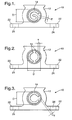
- Fig. 1 is a side elevational view of one aspect of a cooling unit of the disclosed cooling apparatus;
- Fig. 2 is a side elevational view of a second aspect of the cooling unit of Fig. 1;
- Fig. 3 is a side elevational view of a third aspect of the cooling unit of Fig. 1
- Fig. 4 is a top plan view of the cooling unit of Fig. 1; and
- Fig. 5 is a front perspective view of an ECM having the cooling unit of Fig. 3 attached thereto.
- As shown in Figs. 1-4, a cooling unit according to one aspect of the disclosed cooling apparatus and method, generally designated 10, may include an
elongated body 12 having a fluid channel (or fluid channels) 14 extending therethrough for receiving a cooling fluid therein. In one aspect, thebody 12 may have a length L of about 10 to about 100 centimeters. Thefluid channel 14 may have afluid inlet 16 and afluid outlet 18. - In another aspect, the
fluid inlet 16 may be in fluid communication with a fluid source (not shown) such as a fuel tank and thefluid outlet 18 may be in fluid communication with the combustion chamber of an engine (not shown) such that fluid exiting thecooling unit 10 by way of thefluid outlet 18 is passed directly to the engine as fuel. Therefore, the cooling fluid may move though thechannel 14 at a relatively low flow rate. In one aspect, the fluid flow rate through thechannel 14 may be related to the rate that fuel is consumed by the engine (e.g., about 0.25 to about 1.5 liters per minute). - In another aspect, the
unit 10 may be formed from aluminum. However, those skilled in the art will appreciate that theunit 10 may be constructed from various materials (including metals and non-metals) capable of conducting thermal energy without reacting with the cooling fluid. In one aspect, thebody 12 andchannel 14 may be shaped and formed by an aluminum extruding process. - The
cooling unit 10 may be provided with an attachment mechanism for securing thecooling unit 10 to a device requiring cooling. For example, as shown in Fig. 3, thecooling unit 10 may be provided withmounting flanges 22 havingscrew holes 24 therein. As shown in Fig. 4, thecooling unit 10 may be connected to anECM 20 withscrews 26 such that heat generated by theECM 20 is transferred to the cooling fluid by way of thecooling unit 10. However, those skilled in the art will appreciate that thecooling unit 10 may be connected to adevice 20 by any technique or combination of techniques known in the art, including thermal adhesives, welding, rivets, bolts or the like. - As shown in Fig. 1, the
fluid channel 14 may be generally G-shaped in end view. In another aspect, as shown in Fig. 2, thefluid channel 14 may be generally ( )-shaped (i.e., closed parenthesis shaped) in end view. In another aspect, as shown in Fig. 3, thefluid channel 14 may be generally C-shaped in end view. - In one aspect, the
channel 14 may have an overall cross-sectional diameter D of about 10 to about 40 millimeters and thechannel 14 may have a cross-sectional thickness T of about 1 to about 30 millimeters. The generally G-shaped or generally C-shaped channels may be one continuous channel in cross-section or two or more separate channels in cross-section. The generally ( )-shaped channel may be two or more separated channels in cross-section. - Without being limited to any particular theory, it is believed that the "G," "C" and "( )" shaped channels offer improved heat transfer at low, laminar flow rates due to the low thermal resistance and reduced back pressure achieved by the "G," "C" and "( )" geometries. In particular, it is believed that the "G," "C" and "( )" geometries minimize thermal resistance by maximizing the internal surface area (i.e., the flux area) of the
channel 14 while minimizing the boundary layer thickness (i.e., the flow gap width) of theunit 10. Furthermore, it is believed that the "G," "C" and "( )" geometries minimize backpressure by maximizing the cross-sectional flow area of theunit 10, while eliminating sharp corners and intersections. - Two cooling units were prepared as described above using an aluminum extruding process. Each unit was approximately 0.22 meters long. The first unit incorporated a channel having a G-shaped geometry and the second unit incorporated a channel having a ( )-shaped geometry. Each channel had a thickness of about 1.52 mm and an overall diameter of about 14.5 mm. The thermal resistance and backpressure of each unit was determined at various flow rates using mineral oil as the cooling fluid to safely simulate #2 diesel fuel. The results are set forth in Table 1 for the G-shaped channel and Table 2 for the ( )-shaped channel.
Table 1 Flow Rate (l/min.) Thermal Resistance (°C/Watt) Backpressure (psi) 0.25 0.204 0.05 0.5 0.174 0.095 1 0.144 0.19 1.5 0.126 0.28 Table 2 Flow Rate (l/min.) Thermal Resistance (°C/Watt) Backpressure (psi) 0.25 0.215 0.07 0.5 0.184 0.13 1 0.154 0.26 1.5 0.136 0.4 - Accordingly, cooling units having generally G-shaped and generally ( )-shaped cross-sectional geometries may provide improved heat transfer at low, laminar flow rates.
- Although the cooling apparatuses and methods are shown and described with respect to certain aspects, modifications may occur to those skilled in the art upon reading the specification. The cooling apparatuses and methods are limited only by the scope of the claims.
Claims (20)
- A cooling apparatus 10 comprising:an elongated body portion 12 having a fluid inlet 16 and a fluid outlet 18; anda fluid channel 14 extending between said fluid inlet 16 and said fluid outlet 18, wherein said fluid channel 14 includes at least one of a generally G-shaped cross-section, a generally C-shaped cross-section and a generally ( )-shaped cross-section.
- The cooling apparatus 10 of claim 1 wherein said elongated body portion 12 is made of extruded aluminum.
- The cooling apparatus 10 of claim 1 wherein said elongated body portion 12 is about 10 to about 100 centimeters in length.
- The cooling apparatus 10 of claim 1 wherein said fluid inlet 16 is adapted to be placed in fluid communication with a fuel tank.
- The cooling apparatus 10 of claim 1 wherein said fluid outlet 18 is adapted to be placed in fluid communication with a combustion chamber of an engine.
- The cooling apparatus 10 of claim 1 further comprising at least one attachment mechanism 22.
- The cooling apparatus 10 of claim 1 wherein said fluid channel 14 has an overall cross-sectional diameter of about 10 to about 40 millimeters.
- The cooling apparatus 10 of claim 1 wherein said fluid channel 14 has a thickness of about 1 to about 30 millimeters.
- A cooling system comprising:a heated substrate 20;a cooling unit 10 adapted to be mounted on said heated substrate 20, wherein said cooling unit 10 includes an elongated body portion 12 having a fluid inlet 16 and a fluid outlet 18 and a fluid channel 14 extending between said fluid inlet 16 and said fluid outlet 18, wherein said fluid channel 14 includes at least one of a generally G-shaped cross-section, a generally C-shaped cross-section and a generally ( )-shaped cross-section; anda cooling fluid adapted to move through said fluid channel 14 to cool said heated substrate 20.
- The system of claim 9 wherein said heated substrate 20 is an electronic control module.
- The system of claim 10 wherein said cooling fluid is diesel fuel.
- The system of claim 11 wherein said fluid outlet 18 is adapted to be placed in fluid communication with a combustion chamber of a diesel engine and said diesel fuel is passed to said diesel engine after passing through said cooling unit 10.
- The system of claim 9 wherein said elongated body portion 12 is made of extruded aluminum.
- The system of claim 9 wherein said elongated body portion 12 is about 10 to about 100 centimeters in length.
- The system of claim 9 wherein said fluid channel 14 has an overall cross-sectional diameter of about 10 to about 40 millimeters.
- The system of claim 9 wherein said fluid channel 14 has a thickness of about 1 to about 30 millimeters.
- A method for cooling a heated substrate 20 comprising the steps of:providing a cooling unit 10 having an elongated fluid channel 14 extending therethrough, wherein said fluid channel 14 includes at least one of a generally G-shaped cross-section, a generally C-shaped cross-section and a generally ( )-shaped cross-section;contacting said cooling unit 10 to a substrate 20; andpassing a cooling fluid through said fluid channel 14 to cool said substrate 20.
- The method of claim 17 wherein said passing step is performed at a low flow rate.
- The method of claim 17 wherein said cooling fluid is a fuel.
- The method of claim 19 further comprising the step of passing said fuel to a combustion chamber of an engine after said fuel passes through said fluid channel 14.
Applications Claiming Priority (1)
| Application Number | Priority Date | Filing Date | Title |
|---|---|---|---|
| US11/320,123 US20070144498A1 (en) | 2005-12-28 | 2005-12-28 | Cooling apparatus and method using low fluid flow rates |
Publications (1)
| Publication Number | Publication Date |
|---|---|
| EP1804564A1 true EP1804564A1 (en) | 2007-07-04 |
Family
ID=37914262
Family Applications (1)
| Application Number | Title | Priority Date | Filing Date |
|---|---|---|---|
| EP06077255A Withdrawn EP1804564A1 (en) | 2005-12-28 | 2006-12-14 | Cooling apparatus and method using low fluid flow rates |
Country Status (2)
| Country | Link |
|---|---|
| US (1) | US20070144498A1 (en) |
| EP (1) | EP1804564A1 (en) |
Cited By (1)
| Publication number | Priority date | Publication date | Assignee | Title |
|---|---|---|---|---|
| US8629981B2 (en) | 2008-02-01 | 2014-01-14 | Palo Alto Research Center Incorporated | Analyzers with time variation based on color-coded spatial modulation |
Citations (8)
| Publication number | Priority date | Publication date | Assignee | Title |
|---|---|---|---|---|
| JPS5557636A (en) * | 1978-10-25 | 1980-04-28 | Hitachi Ltd | Electronically controlled fuel injection system |
| EP0084179A2 (en) * | 1982-01-14 | 1983-07-27 | Mitsubishi Denki Kabushiki Kaisha | Fuel control apparatus for an internal combustion engine |
| WO1993005285A1 (en) * | 1991-09-09 | 1993-03-18 | Caterpillar Inc. | A piston cooling nozzle |
| JPH08311970A (en) * | 1995-05-17 | 1996-11-26 | Jdc Corp | Rainwater permeation purification pipe |
| GB2327997A (en) * | 1997-07-31 | 1999-02-10 | Raymond Lippiatt | Liner pipe |
| GB2352092A (en) * | 1999-07-13 | 2001-01-17 | Delphi Tech Inc | Cooling motor vehicle control modules. |
| WO2001014699A1 (en) * | 1999-08-23 | 2001-03-01 | Scania Cv Aktiebolag (Publ) | Apparatus for piston cooling and a method for producing a nozzle for such an apparatus |
| US20040050346A1 (en) * | 2002-07-01 | 2004-03-18 | Schenk Charles R. | Lift pump mounting bracket for an electronic control module cooler |
Family Cites Families (7)
| Publication number | Priority date | Publication date | Assignee | Title |
|---|---|---|---|---|
| US4434110A (en) * | 1981-03-23 | 1984-02-28 | Fuel Systems Management | Carburetor, control apparatus and method for internal combustion engines |
| JPS59155564A (en) * | 1983-02-24 | 1984-09-04 | Toyota Motor Corp | Fuel distributing pipe for fuel injection type engine |
| JPH04113778U (en) * | 1991-03-22 | 1992-10-06 | 本田技研工業株式会社 | vehicle fuel cooling system |
| US5343847A (en) * | 1993-09-13 | 1994-09-06 | Pacer Industries, Inc. | Electronic gaseous fuel injection system |
| GB2316773B (en) * | 1996-06-12 | 1999-09-29 | Gas Technology Canada | Electronic gas regulator |
| US6227173B1 (en) * | 1999-06-07 | 2001-05-08 | Bi-Phase Technologies, L.L.C. | Fuel line arrangement for LPG system, and method |
| US6520252B1 (en) * | 2001-12-21 | 2003-02-18 | Hamilton Sundstrand | Heat exchanger assembly with core-reinforcing closure bars |
-
2005
- 2005-12-28 US US11/320,123 patent/US20070144498A1/en not_active Abandoned
-
2006
- 2006-12-14 EP EP06077255A patent/EP1804564A1/en not_active Withdrawn
Patent Citations (8)
| Publication number | Priority date | Publication date | Assignee | Title |
|---|---|---|---|---|
| JPS5557636A (en) * | 1978-10-25 | 1980-04-28 | Hitachi Ltd | Electronically controlled fuel injection system |
| EP0084179A2 (en) * | 1982-01-14 | 1983-07-27 | Mitsubishi Denki Kabushiki Kaisha | Fuel control apparatus for an internal combustion engine |
| WO1993005285A1 (en) * | 1991-09-09 | 1993-03-18 | Caterpillar Inc. | A piston cooling nozzle |
| JPH08311970A (en) * | 1995-05-17 | 1996-11-26 | Jdc Corp | Rainwater permeation purification pipe |
| GB2327997A (en) * | 1997-07-31 | 1999-02-10 | Raymond Lippiatt | Liner pipe |
| GB2352092A (en) * | 1999-07-13 | 2001-01-17 | Delphi Tech Inc | Cooling motor vehicle control modules. |
| WO2001014699A1 (en) * | 1999-08-23 | 2001-03-01 | Scania Cv Aktiebolag (Publ) | Apparatus for piston cooling and a method for producing a nozzle for such an apparatus |
| US20040050346A1 (en) * | 2002-07-01 | 2004-03-18 | Schenk Charles R. | Lift pump mounting bracket for an electronic control module cooler |
Cited By (1)
| Publication number | Priority date | Publication date | Assignee | Title |
|---|---|---|---|---|
| US8629981B2 (en) | 2008-02-01 | 2014-01-14 | Palo Alto Research Center Incorporated | Analyzers with time variation based on color-coded spatial modulation |
Also Published As
| Publication number | Publication date |
|---|---|
| US20070144498A1 (en) | 2007-06-28 |
Similar Documents
| Publication | Publication Date | Title |
|---|---|---|
| WO2004042304A3 (en) | Method and apparatus for efficient vertical fluid delivery for cooling a heat producing device | |
| US11770914B2 (en) | Cooling device and method of manufacturing the same | |
| US8534571B2 (en) | Switchable radiator bypass valve set point to improve energy efficiency | |
| EP1790568A3 (en) | Cabin air conditioning system with liquid cooling for power electronics | |
| CN109661157A (en) | A kind of novel liquid cooling cabinet | |
| DE60220700D1 (en) | HEAT EXCHANGER MODULE WITH MAIN COOLER AND SUBWAY COOLER | |
| CN1957164B (en) | Optimized cooling system for a motor vehicle | |
| US20070144498A1 (en) | Cooling apparatus and method using low fluid flow rates | |
| US20090211736A1 (en) | Coolant circulating apparatus, and cooling apparatus including the same coolant circulating apparatus for electric and/or electronic device which generates heat | |
| CN217804229U (en) | Flow passage plate, heat management integrated module, refrigerant circulation circuit and vehicle | |
| CN115958938A (en) | Hybrid power thermal management system and method coupled with engine cooling system | |
| CN204627699U (en) | A kind of machine oil cooler | |
| CN2612070Y (en) | Liquid cooling radiator | |
| CN220653894U (en) | Vehicle-mounted liquid cooling heat dissipation device | |
| CN220600152U (en) | Heat dissipation assembly of energy-saving hydraulic station | |
| CN2681218Y (en) | Liquid cooling type heat sink | |
| DE10359064B3 (en) | Cooling device for cooling automobile electronic component has separate cooling fan supplied with cold air provided by automobile climate-control unit | |
| CN2909802Y (en) | Water-cooled heat sink with expandable heat-absorbing elements | |
| JPH10205402A (en) | Fuel oil cooler for diesel engine | |
| CN218722547U (en) | Hydraulic oil production heat abstractor | |
| US5745343A (en) | Cubicle for inverter | |
| CN207399725U (en) | A kind of universal liquid cold plate test device | |
| CN222819875U (en) | Thermal management system and electric vehicle | |
| CN113747770A (en) | Radiating assembly with good radiating effect for medical communication device | |
| CN2906491Y (en) | Electronic wine cabinet |
Legal Events
| Date | Code | Title | Description |
|---|---|---|---|
| PUAI | Public reference made under article 153(3) epc to a published international application that has entered the european phase |
Free format text: ORIGINAL CODE: 0009012 |
|
| AK | Designated contracting states |
Kind code of ref document: A1 Designated state(s): AT BE BG CH CY CZ DE DK EE ES FI FR GB GR HU IE IS IT LI LT LU LV MC NL PL PT RO SE SI SK TR |
|
| AX | Request for extension of the european patent |
Extension state: AL BA HR MK YU |
|
| 17P | Request for examination filed |
Effective date: 20080104 |
|
| 17Q | First examination report despatched |
Effective date: 20080206 |
|
| AKX | Designation fees paid |
Designated state(s): AT BE BG CH CY CZ DE DK EE ES FI FR GB GR HU IE IS IT LI LT LU LV MC NL PL PT RO SE SI SK TR |
|
| STAA | Information on the status of an ep patent application or granted ep patent |
Free format text: STATUS: THE APPLICATION IS DEEMED TO BE WITHDRAWN |
|
| 18D | Application deemed to be withdrawn |
Effective date: 20080617 |