EP1804451A2 - Apparatus and method for determining pilot pattern in a broadband wireless access communication system - Google Patents
Apparatus and method for determining pilot pattern in a broadband wireless access communication system Download PDFInfo
- Publication number
- EP1804451A2 EP1804451A2 EP06124823A EP06124823A EP1804451A2 EP 1804451 A2 EP1804451 A2 EP 1804451A2 EP 06124823 A EP06124823 A EP 06124823A EP 06124823 A EP06124823 A EP 06124823A EP 1804451 A2 EP1804451 A2 EP 1804451A2
- Authority
- EP
- European Patent Office
- Prior art keywords
- coherence
- time
- pilot pattern
- pilot
- calculating
- Prior art date
- Legal status (The legal status is an assumption and is not a legal conclusion. Google has not performed a legal analysis and makes no representation as to the accuracy of the status listed.)
- Granted
Links
Images



Classifications
-
- H—ELECTRICITY
- H04—ELECTRIC COMMUNICATION TECHNIQUE
- H04L—TRANSMISSION OF DIGITAL INFORMATION, e.g. TELEGRAPHIC COMMUNICATION
- H04L27/00—Modulated-carrier systems
- H04L27/26—Systems using multi-frequency codes
-
- H—ELECTRICITY
- H04—ELECTRIC COMMUNICATION TECHNIQUE
- H04L—TRANSMISSION OF DIGITAL INFORMATION, e.g. TELEGRAPHIC COMMUNICATION
- H04L27/00—Modulated-carrier systems
- H04L27/26—Systems using multi-frequency codes
- H04L27/2601—Multicarrier modulation systems
- H04L27/2602—Signal structure
- H04L27/261—Details of reference signals
-
- H—ELECTRICITY
- H04—ELECTRIC COMMUNICATION TECHNIQUE
- H04L—TRANSMISSION OF DIGITAL INFORMATION, e.g. TELEGRAPHIC COMMUNICATION
- H04L1/00—Arrangements for detecting or preventing errors in the information received
- H04L1/0001—Systems modifying transmission characteristics according to link quality, e.g. power backoff
-
- H—ELECTRICITY
- H04—ELECTRIC COMMUNICATION TECHNIQUE
- H04L—TRANSMISSION OF DIGITAL INFORMATION, e.g. TELEGRAPHIC COMMUNICATION
- H04L25/00—Baseband systems
- H04L25/02—Details ; arrangements for supplying electrical power along data transmission lines
- H04L25/0202—Channel estimation
- H04L25/0222—Estimation of channel variability, e.g. coherence bandwidth, coherence time, fading frequency
Definitions
- the present invention relates generally to a Broadband Wireless Access (BWA) communication system, and in particular, to an apparatus and method for adaptively changing a pilot pattern according to a link in an Orthogonal Frequency Division Multiplexing (OFDM) communication system.
- BWA Broadband Wireless Access
- OFDM Orthogonal Frequency Division Multiplexing
- OFDM is considered the most prominent future-generation wireless communication technology. It is expected that OFDM will be adopted for most wireless communication applications by the year 2010. OFDM has been adopted as a standard for an Institute of Electrical and Electronics Engineers (IEEE) 802.16 Wireless Metropolitan Area Network (WMAN) categorized into the 3.5 th Generation (3.5G) technology.
- IEEE Institute of Electrical and Electronics Engineers
- WMAN Wireless Metropolitan Area Network
- 3.5G 3.5 th Generation
- a transmitter simultaneously sends pilot subcarrier signals to a receiver with transmission of data subcarrier signals.
- the receiver performs synchronization acquisition, channel estimation, and Base Station (BS) identification using the pilot subcarrier signals.
- BS Base Station
- a transmission rule for sending the pilot subcarrier signals is known as "pilot pattern".
- the pilot pattern is determined in consideration of coherence bandwidth and coherence time.
- the coherence bandwidth is the maximum bandwidth over which a channel is relatively constant or non-distorting in the frequency domain
- the coherence time is the maximum time for which the channel is relatively constant in the time domain. Since the channel can be assumed to be constant over the coherence bandwidth for the coherence time, one pilot signal suffices for synchronization acquisition, channel estimation and BS identification.
- Radio channels are said to be a wide range of random channels and it is difficult to always ensure optimum performance over these random channels with the conventional fixed pilot pattern.
- a layout of pilot subcarriers affects performance according to the link status, which in turn directly influences channel estimation performance. That is, the channel estimation performance may increase according to the pilot pattern. Since the channel estimation performance has an influence on Bit Error Rate (BER), it is important to select a pilot pattern that minimizes channel estimation errors.
- BER Bit Error Rate
- An object of the present invention is to substantially solve at least the above problems and/or disadvantages and to provide at least the advantages below. Accordingly, an object of the present invention is to provide an apparatus and method for adaptively changing a pilot pattern according to a link in a BWA communication system.
- An object of the present invention is to provide an apparatus and method for selecting a pilot pattern that minimizes channel estimation errors in a BWA communication system.
- a further object of the present invention is to provide an apparatus and method for adaptively changing an uplink pilot pattern according to an uplink in a BWA communication system.
- Another object of the present invention is to provide an apparatus and method for selecting a pilot pattern based on the Mean Square Error (MSE) of frequency-domain data in a BWA communication system.
- MSE Mean Square Error
- an OFDM demodulator in an apparatus for determining a pilot pattern in a BWA communication system, generates frequency-domain data by fast-Fourier-transform (FFT)-processing a received signal.
- a pilot pattern decider calculates a coherence bandwidth and a coherence time using subcarrier values received from the OFDM demodulator, and selects one of a plurality of pilot patterns according to the ratio of the coherence bandwidth to the coherence time.
- subcarrier values are generated by FFT-processing a received signal.
- a coherence bandwidth and a coherence time are calculated using the subcarrier values.
- One of a plurality of pilot patterns is selected according to the ratio of the coherence bandwidth to the coherence time.
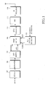
- FIG. 1 is a block diagram of a transmitter in a BWA communication system according to present invention.
- the transmitter is a relative concept, in that it is a Mobile Station (MS) on the uplink and a BS on the downlink.
- MS Mobile Station
- the transmitter includes a pilot pattern generator 100, an encoder 102, a modulator 104, a data mapper 106, a frame buffer 108, an OFDM modulator 110, a Digital-to-Analog Converter (DAC) 112 and a Radio Frequency (RF) processor 114.
- DAC Digital-to-Analog Converter
- RF Radio Frequency
- the encoder 102 encodes an input information bit stream at a coding rate and outputs the resulting coded bits or code symbols. With the number of the information bits being denoted by k and the coding rate being denoted by R, the number of the code symbols is k/R.
- the encoder 102 may be a convolutional encoder, a turbo encoder or a Low Density Parity Check (LDPC) encoder.
- LDPC Low Density Parity Check
- the modulator 104 generates complex symbols by mapping the coded symbols to signal points according to a modulation scheme or modulation level.
- the modulation scheme is one of Binary Phase Shift Keying (BPSK), Quadrature Phase Shift Keying (QPSK), 8-ary Phase Shift Keying (8PSK), 16-ary Quadrature Amplitude Modulation (16QAM) and 64QAM.
- BPSK Binary Phase Shift Keying
- QPSK Quadrature Phase Shift Keying
- 8PSK 8-ary Phase Shift Keying
- 16QAM 16-ary Quadrature Amplitude Modulation
- the data mapper 106 maps the complex symbols to subcarriers according to a control signal received from a higher layer and provides the mapped complex symbols to memory addresses in the frame buffer 108 of an actual frame size.
- the pilot pattern generator 100 selects a pilot pattern according to feedback information (i.e. pilot pattern selection information) received from a receiver and outputs pilot symbols to corresponding addresses of the frame buffer 108 according to the selected pilot pattern. For example, if a frame size is 64x64 and one frame delivers 64 pilot symbols, a 16x4 first pilot pattern and a 4x16 pilot pattern are available. According to the first pilot pattern, the pilot symbols are mapped equidistantly at an interval of 16 on the frequency axis and at an interval of 4 on the time axis. The second pilot pattern indicates that the pilot symbols are mapped equidistantly at an interval of 4 on the frequency axis and at an interval of 16 on the time axis. The first pilot pattern is viable when a coherence bandwidth is greater than a coherence time, while the second pilot pattern is used when the coherence time is greater than the coherence bandwidth.
- feedback information i.e. pilot pattern selection information
- the frame buffer 108 is a buffer for ordering the complex symbols in an actual transmission order, prior to input to the OFDM modulator 110.
- the frame buffer 108 sequentially outputs the buffered complex symbols based on timing synchronization on an OFDM symbol basis.
- the OFDM modulator 110 converts the complex symbols received from the frame buffer 107 to time-domain sample data by Inverse-Fast-Fourier-Transform (IFFT)-processing the complex symbols, and adds a copy of a last part of the sample data to the sample data, thereby generating an OFDM symbol.
- IFFT Inverse-Fast-Fourier-Transform
- the DAC 112 converts the sample data to an analog signal.
- the RF processor 114 including a filter and a front-end unit, processes the analog signal to an RF signal and ends the RF signal on a radio channel through a transmit antenna.
- the transmitted signal experiences a multi-path channel, is added with noise, and then arrives at a receive antenna of the receiver.
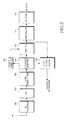
- FIG. 2 is a block diagram of a receiver in the BWA communication system according to the present invention.
- the receiver is a relative concept, in that the BS is the receiver on the uplink and the MS is the receiver on the downlink.
- the receiver includes a pilot pattern decider 200, an RF processor 202, an Analog-to-Digital Converter (ADC) 204, an OFDM demodulator 206, a subcarrier demapper 208, an equalizer 210, a demodulator 212, a decoder 214 and a channel estimator 216.
- ADC Analog-to-Digital Converter
- the RF processor 202 including a front-end unit and a filter, downconverts an RF signal received on a radio channel to a baseband signal.
- the ADC 204 converts the analog baseband signal received form the RF processor 202 to a digital signal.
- the OFDM demodulator 206 removes a Cyclic Prefix (CP) from the digital data and generates frequency-domain data by FFT-processing the CP-removed data.
- CP Cyclic Prefix
- the subcarrier demapper 208 extracts data symbols from the OFDM-demodulated data received from the OFDM demodulator 206 and outputs the data symbols to the equalizer 210. It also extracts pilot symbols at pilot subcarrier positions and provides the extracted pilot symbols to the channel estimator 216.
- the channel estimator 216 performs channel estimation using the pilot symbols.
- the equalizer 210 channel-compensates the received data symbols based on channel estimate values received from the channel estimator 216, that is, compensates for noise created on the radio channel.
- the demodulator 212 demodulates the symbols received form the equalizer in accordance with the modulation scheme used in the transmitter and outputs the resulting coded data.
- the decoder 214 decodes the coded data corresponding to the coding method used in the transmitter, thereby recovering the original information data.
- the pilot pattern decider 200 calculates the mean square error (MSE) of each of the channel-compensated subcarrier values received from the equalizer 210 and calculates a coherence bandwidth and a coherence time by accumulating the MSEs on the frequency and time axes.
- the pilot pattern decider 200 selects a pilot pattern by comparing the ratio of the coherence bandwidth to the coherence time with a threshold value and generates feedback information indicating the selected pilot pattern. The feedback information is sent to the transmitter on a feedback channel.
- MSE mean square error
- a pilot pattern is selected which maps pilot symbols densely along the time axis. If the coherence time is greater than the coherence bandwidth, a pilot pattern is selected which maps pilot symbols densely along the frequency axis.
- FIG. 3 is a detailed block diagram of the pilot pattern decider 200 illustrated in FIG. 2.
- the pilot pattern decider 200 includes a frame buffer 300, a mean square error (MSE) calculator 302, a frequency-axis accumulator 304, a time-axis accumulator 306, a first arranger 308, a second arranger 310, a first selector 312, a second selector 314, a first adder 316, a second adder 318, a ratio calculator 320 and a pilot pattern selector 322.
- MSE mean square error
- the frame buffer 300 buffers the frequency-domain frame data received form the equalizer 210.
- a 64x64 frame size (40964 subcarrier values) is assumed.
- the MSE calculator 302 calculates the MSEs of the subcarrier values (received complex symbols) received from the frame buffer 300.
- the MSEs can be calculated in any one of known methods and a description of the MSE calculation will not be provided herein.
- the frequency-axis accumulator 304 accumulates the calculated 64x64 MSE values along the frequency axis or column by column, thereby creating 64 accumulation values.
- the time-axis accumulator 306 accumulates the calculated 64x64 MSE values along the time axis or row by row, thereby creating 64 accumulation values.
- the first arranger 308 orders the 64 accumulation values received from the frequency-axis accumulator 304 in a descending order
- the second arranger 310 orders the 64 accumulation values received from the time-axis accumulator 306 in a descending order.
- the first selector 312 selects a number of (e.g. 32) accumulation values among the ordered accumulation values from the first arranger, starting from the highest accumulation value
- the second selector 314 selects a number of (e.g. 32) accumulation values among the ordered accumulation values from the second arranger 310, starting from the highest accumulation value.
- the first adder 316 generates a value C b indicating the coherence bandwidth by summing the accumulation values received the first selector 312, and the second adder 318 generates a value C t indicating the coherence time by summing the accumulation values received from the second selector 314.
- the ratio calculator 320 calculates the ratio R of the coherence bandwidth to the coherence time by dividing C b by C t and then calculating the Log 10 of the division result.
- the pilot pattern selector 322 compares the ratio R with a threshold value, selects a pilot pattern based on the comparison adaptively according to the link, and generates feedback information indicating the selected pilot pattern.
- the ratio R may be inaccurate when too a small number of MSEs are in an entire frame.
- the sum of C b and C t is compared with a threshold value. If the sum is less than the threshold value, a pilot pattern is selected based on the average of previous C b to C t ratio.
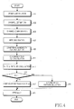
- FIG 4 is a flowchart illustrating an operation for feeding back a pilot pattern in the receiver in the BWA communication system according to the present invention.
- the receiver downconverts an RF signal received through an antenna to a baseband signal and OFDM-demodulates the baseband signal, thus acquiring frequency-domain data in step 401.
- the receiver extracts symbols at subcarrier positions (i.e. pilot symbols) from the frequency-domain data and performs channel estimation using the extracted symbols.
- subcarrier positions i.e. pilot symbols
- the receiver channel-compensates the frequency-domain data using channel estimate values in step 405 and calculates the MSEs of the channel-compensated subcarrier values (complex symbols) in step 407.
- step 409 the receiver accumulates the MSE values along the frequency axis, selects a number of accumulation values in a descending order, and sums them. The sum is the coherence bandwidth C b .
- step 411 the receiver accumulates the MSE values along the time axis, selects a number of accumulation values in a descending order, and sums them. The sum is the coherence time C t .
- the receiver calculates the ratio R of the coherence bandwidth to the coherence time by dividing C b by C t and calculating the Log 10 of the division result in step 413.
- step 415 the receiver compares the ratio R with 1. If R is less than 1, which implies that the coherence bandwidth is greater than the coherence time, the receiver selects a first pilot pattern in which pilot symbols are mapped more densely along the time axis in step 417.
- the receiver selects a second pilot pattern in which pilot symbols are mapped more densely along the frequency axis in step 419.
- the receiver After selecting the pilot pattern, the receiver generates feedback information indicating the selected pilot pattern and sends the feedback information on the feedback channel to the transmitter in step 421.
- FIG. 5 is a graph illustrating a first embodiment of a pilot pattern selection method according to the present invention. A 64x64 frame size and mapping of 64 pilot symbols per frame are assumed.
- a pilot pattern is selected in which the ratio R (C b /C t ) converges to 1. If the coherence bandwidth is greater than the coherence time, the 16x4 first pilot pattern is selected in which pilot symbols are mapped at an interval of 16 along the frequency axis and at an interval of 4 along the time axis. If the coherence time is greater than the coherence bandwidth, the 4x16 second pilot pattern is selected in which pilot symbols are mapped at an interval of 4 along the frequency axis and at an interval of 16 along the time axis. In this manner, although the same number of pilot symbols are allocated to each frame, the layout of the pilot symbols is adapted to the link status.
- FIG. 6 is a graph illustrating a second embodiment of a pilot pattern selection method according to the present invention.
- two thresholds are set for pilot pattern switching. If the ratio R (C b /C t ) is greater than a first threshold, the 16x4 first pilot pattern is selected. If the ratio R is between the first and second thresholds, an 8x8 third pilot pattern is selected in which pilot symbols are mapped at an interval of 8 along the frequency axis and at an interval of 8 along the time axis. If the ratio R is less than the second threshold, the 4x16 second pilot pattern is selected.
- This pilot pattern selection method leads to robust operation against factors such as sudden channel changes or frame delay by use of a smooth transitional pattern.
- the first and second thresholds are empirically obtained.
- Table 1 Carrier frequency 5 GHz FFT size 1024 (16 users) Bandwidth 40MHz Symbol length 25.6 ⁇ s Guard interval 3.2 ⁇ s (T/8) Max delay spread 5ns, 10ns Mobile velocity 5km/h, 160km/h Modulation QPSK Channel estimator Bilinear interpolation Pilot patterns used 3 (4x16, 8x8, 16x4) Pilot density ⁇ 2% User frame size 64x64 Channels AWGN, 3-ray indoor
- FIG. 7 is a graph comparing the present invention using an adaptive pilot pattern with a conventional technology using a fixed pilot pattern in terms of performance.
- the horizontal axis represents received signal strength (E b /N o ) and the vertical axis represents Bit Error Rate (BER).
- the adaptive pilot pattern method of the present invention outperforms the conventional fixed pilot pattern method.
- the present invention advantageously reduces channel estimation errors by adaptively mapping the same number of pilot symbols in a different layout according to the link status.
- the minimization of channel estimation errors leads to the increase of data BER.
- the present invention reduces signaling overhead by switching a pilot pattern on a frame-by-frame basis.
Landscapes
- Engineering & Computer Science (AREA)
- Computer Networks & Wireless Communication (AREA)
- Signal Processing (AREA)
- Mobile Radio Communication Systems (AREA)
Abstract
Description
- This application claims priority under 35 U.S.C. § 119 to an application filed in the
Korean Intellectual Property Office on December 29, 2005 and assigned Serial No. 2005-132859 - The present invention relates generally to a Broadband Wireless Access (BWA) communication system, and in particular, to an apparatus and method for adaptively changing a pilot pattern according to a link in an Orthogonal Frequency Division Multiplexing (OFDM) communication system.
- Although there are many wireless communication technologies proposed as candidates for high-speed mobile communications, OFDM is considered the most prominent future-generation wireless communication technology. It is expected that OFDM will be adopted for most wireless communication applications by the year 2010. OFDM has been adopted as a standard for an Institute of Electrical and Electronics Engineers (IEEE) 802.16 Wireless Metropolitan Area Network (WMAN) categorized into the 3.5th Generation (3.5G) technology.
- In a conventional OFDM communication system, a transmitter simultaneously sends pilot subcarrier signals to a receiver with transmission of data subcarrier signals. The receiver performs synchronization acquisition, channel estimation, and Base Station (BS) identification using the pilot subcarrier signals. A transmission rule for sending the pilot subcarrier signals is known as "pilot pattern".
- The pilot pattern is determined in consideration of coherence bandwidth and coherence time. The coherence bandwidth is the maximum bandwidth over which a channel is relatively constant or non-distorting in the frequency domain, and the coherence time is the maximum time for which the channel is relatively constant in the time domain. Since the channel can be assumed to be constant over the coherence bandwidth for the coherence time, one pilot signal suffices for synchronization acquisition, channel estimation and BS identification.
- Conventionally, a fixed pilot pattern is used and existing adaptive pilot pattern techniques focus on optimization of pilot power and throughput. A technique for adaptively changing a pilot pattern according to a link status (e.g. coherence bandwidth and coherence time) is yet to be developed.
- Radio channels are said to be a wide range of random channels and it is difficult to always ensure optimum performance over these random channels with the conventional fixed pilot pattern. Assuming that a pilot pattern is created using the same number of pilots, a layout of pilot subcarriers affects performance according to the link status, which in turn directly influences channel estimation performance. That is, the channel estimation performance may increase according to the pilot pattern. Since the channel estimation performance has an influence on Bit Error Rate (BER), it is important to select a pilot pattern that minimizes channel estimation errors.
- An object of the present invention is to substantially solve at least the above problems and/or disadvantages and to provide at least the advantages below. Accordingly, an object of the present invention is to provide an apparatus and method for adaptively changing a pilot pattern according to a link in a BWA communication system.
- An object of the present invention is to provide an apparatus and method for selecting a pilot pattern that minimizes channel estimation errors in a BWA communication system.
- A further object of the present invention is to provide an apparatus and method for adaptively changing an uplink pilot pattern according to an uplink in a BWA communication system.
- Another object of the present invention is to provide an apparatus and method for selecting a pilot pattern based on the Mean Square Error (MSE) of frequency-domain data in a BWA communication system.
- According to the present invention, in an apparatus for determining a pilot pattern in a BWA communication system, an OFDM demodulator generates frequency-domain data by fast-Fourier-transform (FFT)-processing a received signal. A pilot pattern decider calculates a coherence bandwidth and a coherence time using subcarrier values received from the OFDM demodulator, and selects one of a plurality of pilot patterns according to the ratio of the coherence bandwidth to the coherence time.
- According to the present invention, in a method of determining a pilot pattern in a BWA communication system, subcarrier values are generated by FFT-processing a received signal. A coherence bandwidth and a coherence time are calculated using the subcarrier values. One of a plurality of pilot patterns is selected according to the ratio of the coherence bandwidth to the coherence time.
- The above and other objects, features and advantages of the present invention will become more apparent from the following detailed description when taken in conjunction with the accompanying drawings in which:
- FIG. 1 is a block diagram of a transmitter in a BWA communication system according to the present invention;
- FIG. 2 is a block diagram of a receiver in the BWA communication system according to the present invention;
- FIG. 3 is a detailed block diagram of a pilot pattern decider illustrated in FIG. 2;
- FIG. 4 is a flowchart illustrating an operation for feeding back a pilot pattern in the receiver in the BWA communication system according to the present invention;
- FIG. 5 is a graph illustrating a first embodiment of a pilot pattern selection method according to the present invention;
- FIG. 6 is a graph illustrating a second embodiment of a pilot pattern selection method according to the present invention; and
- FIG. 7 is a graph comparing the present invention using an adaptive pilot pattern with a conventional technology using a fixed pilot pattern in terms of performance.
- Preferred embodiments of the present invention will be described herein below with reference to the accompanying drawings. In the following description, well-known functions or constructions are not described in detail for the sake of clarity and conciseness.
- FIG. 1 is a block diagram of a transmitter in a BWA communication system according to present invention. The transmitter is a relative concept, in that it is a Mobile Station (MS) on the uplink and a BS on the downlink.
- Referring to FIG. 1, the transmitter includes a
pilot pattern generator 100, anencoder 102, amodulator 104, adata mapper 106, aframe buffer 108, anOFDM modulator 110, a Digital-to-Analog Converter (DAC) 112 and a Radio Frequency (RF)processor 114. - In operation, the
encoder 102 encodes an input information bit stream at a coding rate and outputs the resulting coded bits or code symbols. With the number of the information bits being denoted by k and the coding rate being denoted by R, the number of the code symbols is k/R. Theencoder 102 may be a convolutional encoder, a turbo encoder or a Low Density Parity Check (LDPC) encoder. - The
modulator 104 generates complex symbols by mapping the coded symbols to signal points according to a modulation scheme or modulation level. For example, the modulation scheme is one of Binary Phase Shift Keying (BPSK), Quadrature Phase Shift Keying (QPSK), 8-ary Phase Shift Keying (8PSK), 16-ary Quadrature Amplitude Modulation (16QAM) and 64QAM. One bit (s=1) is mapped to one signal point (i.e. complex symbol) in BPSK, two bits (s=2) are mapped to one signal point in QPSK, three bits (s=3) are mapped to one signal point in 8PSK, four bits (s=4) are mapped to one signal point in 16QAM and six bits (s=6) are mapped to one signal point in 64QAM. - The
data mapper 106 maps the complex symbols to subcarriers according to a control signal received from a higher layer and provides the mapped complex symbols to memory addresses in theframe buffer 108 of an actual frame size. - The
pilot pattern generator 100 selects a pilot pattern according to feedback information (i.e. pilot pattern selection information) received from a receiver and outputs pilot symbols to corresponding addresses of theframe buffer 108 according to the selected pilot pattern. For example, if a frame size is 64x64 and one frame delivers 64 pilot symbols, a 16x4 first pilot pattern and a 4x16 pilot pattern are available. According to the first pilot pattern, the pilot symbols are mapped equidistantly at an interval of 16 on the frequency axis and at an interval of 4 on the time axis. The second pilot pattern indicates that the pilot symbols are mapped equidistantly at an interval of 4 on the frequency axis and at an interval of 16 on the time axis. The first pilot pattern is viable when a coherence bandwidth is greater than a coherence time, while the second pilot pattern is used when the coherence time is greater than the coherence bandwidth. - The
frame buffer 108 is a buffer for ordering the complex symbols in an actual transmission order, prior to input to theOFDM modulator 110. Theframe buffer 108 sequentially outputs the buffered complex symbols based on timing synchronization on an OFDM symbol basis. - The
OFDM modulator 110 converts the complex symbols received from the frame buffer 107 to time-domain sample data by Inverse-Fast-Fourier-Transform (IFFT)-processing the complex symbols, and adds a copy of a last part of the sample data to the sample data, thereby generating an OFDM symbol. - The
DAC 112 converts the sample data to an analog signal. TheRF processor 114, including a filter and a front-end unit, processes the analog signal to an RF signal and ends the RF signal on a radio channel through a transmit antenna. The transmitted signal experiences a multi-path channel, is added with noise, and then arrives at a receive antenna of the receiver. - FIG. 2 is a block diagram of a receiver in the BWA communication system according to the present invention. The receiver is a relative concept, in that the BS is the receiver on the uplink and the MS is the receiver on the downlink.
- Referring to FIG. 2, the receiver includes a
pilot pattern decider 200, anRF processor 202, an Analog-to-Digital Converter (ADC) 204, anOFDM demodulator 206, asubcarrier demapper 208, anequalizer 210, ademodulator 212, adecoder 214 and achannel estimator 216. - In operation, the
RF processor 202, including a front-end unit and a filter, downconverts an RF signal received on a radio channel to a baseband signal. TheADC 204 converts the analog baseband signal received form theRF processor 202 to a digital signal. - The OFDM demodulator 206 removes a Cyclic Prefix (CP) from the digital data and generates frequency-domain data by FFT-processing the CP-removed data.
- The subcarrier demapper 208 extracts data symbols from the OFDM-demodulated data received from the
OFDM demodulator 206 and outputs the data symbols to theequalizer 210. It also extracts pilot symbols at pilot subcarrier positions and provides the extracted pilot symbols to thechannel estimator 216. - The
channel estimator 216 performs channel estimation using the pilot symbols. Theequalizer 210 channel-compensates the received data symbols based on channel estimate values received from thechannel estimator 216, that is, compensates for noise created on the radio channel. - The
demodulator 212 demodulates the symbols received form the equalizer in accordance with the modulation scheme used in the transmitter and outputs the resulting coded data. Thedecoder 214 decodes the coded data corresponding to the coding method used in the transmitter, thereby recovering the original information data. - The
pilot pattern decider 200 calculates the mean square error (MSE) of each of the channel-compensated subcarrier values received from theequalizer 210 and calculates a coherence bandwidth and a coherence time by accumulating the MSEs on the frequency and time axes. Thepilot pattern decider 200 selects a pilot pattern by comparing the ratio of the coherence bandwidth to the coherence time with a threshold value and generates feedback information indicating the selected pilot pattern. The feedback information is sent to the transmitter on a feedback channel. - If the coherence bandwidth is greater than the coherence time, a pilot pattern is selected which maps pilot symbols densely along the time axis. If the coherence time is greater than the coherence bandwidth, a pilot pattern is selected which maps pilot symbols densely along the frequency axis.
- FIG. 3 is a detailed block diagram of the
pilot pattern decider 200 illustrated in FIG. 2. - Referring to FIG. 3, the
pilot pattern decider 200 includes aframe buffer 300, a mean square error (MSE)calculator 302, a frequency-axis accumulator 304, a time-axis accumulator 306, afirst arranger 308, asecond arranger 310, afirst selector 312, asecond selector 314, afirst adder 316, asecond adder 318, aratio calculator 320 and apilot pattern selector 322. - In operation, the
frame buffer 300 buffers the frequency-domain frame data received form theequalizer 210. A 64x64 frame size (40964 subcarrier values) is assumed. TheMSE calculator 302 calculates the MSEs of the subcarrier values (received complex symbols) received from theframe buffer 300. The MSEs can be calculated in any one of known methods and a description of the MSE calculation will not be provided herein. - The frequency-
axis accumulator 304 accumulates the calculated 64x64 MSE values along the frequency axis or column by column, thereby creating 64 accumulation values. The time-axis accumulator 306 accumulates the calculated 64x64 MSE values along the time axis or row by row, thereby creating 64 accumulation values. - The
first arranger 308 orders the 64 accumulation values received from the frequency-axis accumulator 304 in a descending order, and thesecond arranger 310 orders the 64 accumulation values received from the time-axis accumulator 306 in a descending order. - The
first selector 312 selects a number of (e.g. 32) accumulation values among the ordered accumulation values from the first arranger, starting from the highest accumulation value, and thesecond selector 314 selects a number of (e.g. 32) accumulation values among the ordered accumulation values from thesecond arranger 310, starting from the highest accumulation value. - The
first adder 316 generates a value Cb indicating the coherence bandwidth by summing the accumulation values received thefirst selector 312, and thesecond adder 318 generates a value Ct indicating the coherence time by summing the accumulation values received from thesecond selector 314. - The
ratio calculator 320 calculates the ratio R of the coherence bandwidth to the coherence time by dividing Cb by Ct and then calculating theLog 10 of the division result. - The
pilot pattern selector 322 compares the ratio R with a threshold value, selects a pilot pattern based on the comparison adaptively according to the link, and generates feedback information indicating the selected pilot pattern. - The ratio R may be inaccurate when too a small number of MSEs are in an entire frame. In this case, the sum of Cb and Ct is compared with a threshold value. If the sum is less than the threshold value, a pilot pattern is selected based on the average of previous Cb to Ct ratio.
- FIG 4 is a flowchart illustrating an operation for feeding back a pilot pattern in the receiver in the BWA communication system according to the present invention.
- Referring to FIG 4, the receiver downconverts an RF signal received through an antenna to a baseband signal and OFDM-demodulates the baseband signal, thus acquiring frequency-domain data in
step 401. - In
step 403, the receiver extracts symbols at subcarrier positions (i.e. pilot symbols) from the frequency-domain data and performs channel estimation using the extracted symbols. - The receiver channel-compensates the frequency-domain data using channel estimate values in
step 405 and calculates the MSEs of the channel-compensated subcarrier values (complex symbols) instep 407. - In
step 409, the receiver accumulates the MSE values along the frequency axis, selects a number of accumulation values in a descending order, and sums them. The sum is the coherence bandwidth Cb. Instep 411, the receiver accumulates the MSE values along the time axis, selects a number of accumulation values in a descending order, and sums them. The sum is the coherence time Ct. - The receiver calculates the ratio R of the coherence bandwidth to the coherence time by dividing Cb by Ct and calculating the
Log 10 of the division result in step 413. - In
step 415, the receiver compares the ratio R with 1. If R is less than 1, which implies that the coherence bandwidth is greater than the coherence time, the receiver selects a first pilot pattern in which pilot symbols are mapped more densely along the time axis in step 417. - If R is equal to or greater than 1, which implies that the coherence time is greater than the coherence bandwidth, the receiver selects a second pilot pattern in which pilot symbols are mapped more densely along the frequency axis in
step 419. - After selecting the pilot pattern, the receiver generates feedback information indicating the selected pilot pattern and sends the feedback information on the feedback channel to the transmitter in
step 421. - FIG. 5 is a graph illustrating a first embodiment of a pilot pattern selection method according to the present invention. A 64x64 frame size and mapping of 64 pilot symbols per frame are assumed.
- Referring to FIG. 5, a pilot pattern is selected in which the ratio R (Cb/Ct) converges to 1. If the coherence bandwidth is greater than the coherence time, the 16x4 first pilot pattern is selected in which pilot symbols are mapped at an interval of 16 along the frequency axis and at an interval of 4 along the time axis. If the coherence time is greater than the coherence bandwidth, the 4x16 second pilot pattern is selected in which pilot symbols are mapped at an interval of 4 along the frequency axis and at an interval of 16 along the time axis. In this manner, although the same number of pilot symbols are allocated to each frame, the layout of the pilot symbols is adapted to the link status.
- FIG. 6 is a graph illustrating a second embodiment of a pilot pattern selection method according to the present invention.
- Referring to FIG. 6, two thresholds are set for pilot pattern switching. If the ratio R (Cb/Ct) is greater than a first threshold, the 16x4 first pilot pattern is selected. If the ratio R is between the first and second thresholds, an 8x8 third pilot pattern is selected in which pilot symbols are mapped at an interval of 8 along the frequency axis and at an interval of 8 along the time axis. If the ratio R is less than the second threshold, the 4x16 second pilot pattern is selected. This pilot pattern selection method leads to robust operation against factors such as sudden channel changes or frame delay by use of a smooth transitional pattern. Preferably, the first and second thresholds are empirically obtained.
- A simulation was performed to verify the performance of the present invention, under the following parameters listed in Table 1.
Table 1 Carrier frequency 5 GHz FFT size 1024 (16 users) Bandwidth 40MHz Symbol length 25.6µs Guard interval 3.2µs (T/8) Max delay spread 5ns, 10ns Mobile velocity 5km/h, 160km/h Modulation QPSK Channel estimator Bilinear interpolation Pilot patterns used 3 (4x16, 8x8, 16x4) Pilot density < 2% User frame size 64x64 Channels AWGN, 3-ray indoor - FIG. 7 is a graph comparing the present invention using an adaptive pilot pattern with a conventional technology using a fixed pilot pattern in terms of performance.
- Referring to FIG. 7, the horizontal axis represents received signal strength (Eb/No) and the vertical axis represents Bit Error Rate (BER). As noted from the graph, the adaptive pilot pattern method of the present invention outperforms the conventional fixed pilot pattern method.
- As described above, the present invention advantageously reduces channel estimation errors by adaptively mapping the same number of pilot symbols in a different layout according to the link status. The minimization of channel estimation errors leads to the increase of data BER. Also, the present invention reduces signaling overhead by switching a pilot pattern on a frame-by-frame basis.
- While the invention has been shown and described with reference to certain preferred embodiments thereof, it will be understood by those skilled in the art that various changes in form and details may be made therein without departing from the spirit and scope of the invention as defined by the appended claims.
Claims (22)
- An apparatus for determining a pilot pattern in a wireless communication system, comprising:an orthogonal frequency division multiplexing (OFDM) demodulator for generating frequency-domain data by fast-Fourier-transform (FFT)-processing a received signal; anda pilot pattern decider for calculating a coherence bandwidth and a coherence time using subcarrier values received from the OFDM demodulator, and selecting one of a plurality of pilot patterns according to a ratio of the coherence bandwidth to the coherence time.
- The apparatus of claim 1, further comprising an equalizer for channel-compensating the subcarrier values received from the OFDM demodulator and providing the channel-compensated subcarrier values to the pilot pattern decider.
- The apparatus of claim 1, wherein the pilot pattern decider comprises:a mean square error (MSE) calculator for calculating the MSE of each of the subcarrier values;a first calculator for calculating the coherence bandwidth by accumulation the MSEs along a frequency axis;a second calculator for calculating the coherence time by accumulation the MSEs along a time axis; anda pattern selector for selecting the pilot pattern according to the ratio of coherence bandwidth to the coherence time.
- The apparatus of claim 3, wherein the first calculator comprises:a frequency-axis accumulator for accumulating the MSEs along the frequency axis;a selector for selecting a number of accumulation values among the accumulations values generated in the frequency-axis accumulator in a descending order; andan adder for calculating the coherence bandwidth by summing the selected accumulation values.
- The apparatus of claim 3, wherein the second calculator comprises:a time-axis accumulator for accumulating the MSEs along the time axis;a selector for selecting a number of accumulation values among the accumulations values generated in the time-axis accumulator in a descending order; andan adder for calculating the coherence time by summing the selected accumulation values.
- The apparatus of claim 3, wherein the pattern selector selects a pilot pattern in which the ratio of the coherence bandwidth to the coherence time converges to 1.
- The apparatus of claim 3, wherein the pattern selector selects a pilot pattern that allocates more pilot symbols to the time axis than to the frequency axis if the coherence bandwidth is greater than the coherence time.
- The apparatus of claim 3, wherein the pattern selector selects a pilot pattern that allocates more pilot symbols to the frequency axis than to the time axis if the coherence time is greater than the coherence bandwidth.
- The apparatus of claim 3, wherein the pattern selector selects a pilot pattern based on an average of previous coherence bandwidth to coherence time ratio if the sum of the coherence bandwidth and the coherence time is less than a threshold.
- The apparatus of claim 1, wherein information indicating the selected pilot pattern is sent to a transmitter on a feedback channel.
- The apparatus of claim 1, wherein the pilot pattern decider selects a pilot pattern on a frame-by-frame basis.
- A method of determining a pilot pattern in a wireless communication system, comprising the steps of:generating subcarrier values by fast-Fourier-transform (FFT)-processing a received signal;calculating a coherence bandwidth and a coherence time using the subcarrier values; andselecting one of a plurality of pilot patterns according to a ratio of the coherence bandwidth to the coherence time.
- The method of claim 12, further comprising channel-compensating the subcarrier values and providing the channel-compensated subcarrier values for use in calculating the coherence bandwidth and the coherence time.
- The method of claim 12, wherein calculating the coherence bandwidth and the coherence time further comprises:calculating a mean square error (MSE) of each of the subcarrier values;calculating the coherence bandwidth by accumulating the MSEs along a frequency axis; andcalculating the coherence time by accumulating the MSEs along a time axis.
- The method of claim 14, wherein calculating the coherence bandwidth further comprises:accumulating the MSEs along the frequency axis;selecting a number of accumulation values among the accumulations values in a descending order; andcalculating the coherence bandwidth by summing the selected accumulation values.
- The method of claim 14, wherein calculating the coherence time further comprises:accumulating the MSEs along the time axis;selecting a number of accumulation values among the accumulations values in a descending order; andcalculating the coherence time by summing the selected accumulation values.
- The method of claim 12, wherein selecting one of a plurality of pilot patterns further comprises:calculating the ratio of the coherence bandwidth to the coherence time; andselecting a pilot pattern in which the ratio of the coherence bandwidth to the coherence time converges to 1.
- The method of claim 12, wherein selecting one of a plurality of pilot patterns further comprises:calculating a ratio of the coherence bandwidth to the coherence time;selecting a pilot pattern that allocates more pilot symbols to the time axis than to the frequency axis, if the ratio is greater than a first threshold; andselecting a pilot pattern that allocates more pilot symbols to the frequency axis than to the time axis, if the ratio is less than a second threshold
- The method of claim 18, wherein selecting one of a plurality of pilot patterns further comprises selecting a pilot pattern that allocates pilot symbols equally along the frequency axis and the time axis, if the ratio is greater than the second threshold and less than the first threshold.
- The method of claim 18, wherein selecting one of a plurality of pilot patterns further comprises selecting a pilot pattern based on the average of previous coherence bandwidth to coherence time ratio, if the sum of the coherence bandwidth and the coherence time is less than a threshold.
- The method of claim 12, further comprising sending information indicating the selected pilot pattern to a transmitter on a feedback channel.
- The method of claim 12, wherein selecting one of a plurality of pilot patterns further comprises selecting a pilot pattern on a frame-by-frame basis.
Applications Claiming Priority (1)
| Application Number | Priority Date | Filing Date | Title |
|---|---|---|---|
| KR1020050132859A KR100872043B1 (en) | 2005-12-29 | 2005-12-29 | Apparatus and method for determining pilot pattern in broadband wireless access communication system |
Publications (3)
| Publication Number | Publication Date |
|---|---|
| EP1804451A2 true EP1804451A2 (en) | 2007-07-04 |
| EP1804451A3 EP1804451A3 (en) | 2012-12-05 |
| EP1804451B1 EP1804451B1 (en) | 2019-01-02 |
Family
ID=37998360
Family Applications (1)
| Application Number | Title | Priority Date | Filing Date |
|---|---|---|---|
| EP06124823.3A Ceased EP1804451B1 (en) | 2005-12-29 | 2006-11-27 | Apparatus and method for determining pilot pattern in a broadband wireless access communication system |
Country Status (3)
| Country | Link |
|---|---|
| US (1) | US7792201B2 (en) |
| EP (1) | EP1804451B1 (en) |
| KR (1) | KR100872043B1 (en) |
Cited By (3)
| Publication number | Priority date | Publication date | Assignee | Title |
|---|---|---|---|---|
| WO2009040747A3 (en) * | 2007-09-28 | 2009-05-22 | Koninkl Philips Electronics Nv | Change of pilot symbol pattern |
| WO2012045448A1 (en) * | 2010-10-07 | 2012-04-12 | Lantiq Deutschland Gmbh | Dynamic pilot placement |
| WO2017132806A1 (en) * | 2016-02-01 | 2017-08-10 | 华为技术有限公司 | Method for configuring pilot signal, and first device |
Families Citing this family (12)
| Publication number | Priority date | Publication date | Assignee | Title |
|---|---|---|---|---|
| KR100872043B1 (en) * | 2005-12-29 | 2008-12-05 | 삼성전자주식회사 | Apparatus and method for determining pilot pattern in broadband wireless access communication system |
| US20080159448A1 (en) * | 2006-12-29 | 2008-07-03 | Texas Instruments, Incorporated | System and method for crosstalk cancellation |
| WO2008129476A2 (en) * | 2007-04-24 | 2008-10-30 | Koninklijke Philips Electronics N.V. | Pilot allocation in single frequency network |
| GB2449935A (en) * | 2007-06-08 | 2008-12-10 | Fujitsu Ltd | Closed loop MIMO communication system using SISO r.m.s. delay spread to estimate eigen coherence bandwidth. |
| PL2131540T3 (en) * | 2008-06-04 | 2013-12-31 | Sony Corp | New frame structure for multi-carrier systems |
| US8194529B2 (en) | 2008-09-08 | 2012-06-05 | Sony Corporation | Frame and data pattern structure for multi-carrier systems |
| US8203929B2 (en) * | 2008-10-09 | 2012-06-19 | Sony Corporation | Frame and data pattern structure for multi-carrier systems |
| KR101083081B1 (en) | 2008-12-15 | 2011-11-16 | 한국전자통신연구원 | Transmission Time Calculation Method and Apparatus for Inserting Pattern for Channel Estimation in Orthogonal Frequency Division System |
| US8275319B2 (en) * | 2009-03-11 | 2012-09-25 | Broadcom Corporation | Processing of multi-carrier signals before power amplifier amplification |
| WO2013058599A1 (en) * | 2011-10-19 | 2013-04-25 | 엘지전자 주식회사 | Method and apparatus for transceiving downlink control information in a wireless access system |
| CN104838603B (en) * | 2012-12-04 | 2017-11-14 | Lg电子株式会社 | The method of the pattern of reference signal and its equipment are changed according to coherence time change in a wireless communication system |
| US10708796B2 (en) * | 2016-04-21 | 2020-07-07 | Qualcomm Incorporated | High doppler channel performance enhancement |
Family Cites Families (45)
| Publication number | Priority date | Publication date | Assignee | Title |
|---|---|---|---|---|
| US5589763A (en) * | 1995-05-16 | 1996-12-31 | Texas Instruments Incorporated | Coherent undersampling digitizer for use with automatic field test equipment |
| EP0939527B1 (en) * | 1998-02-18 | 2007-12-05 | Sony Deutschland GmbH | Mapping of multicarrier signals into GSM time slots |
| WO2000065756A1 (en) * | 1999-04-22 | 2000-11-02 | Nippon Telegraph And Telephone Corporation | Ofdm packet communication receiver |
| US6385264B1 (en) * | 1999-06-08 | 2002-05-07 | Qualcomm Incorporated | Method and apparatus for mitigating interference between base stations in a wideband CDMA system |
| KR100526499B1 (en) * | 2000-08-22 | 2005-11-08 | 삼성전자주식회사 | Apparatus for transmit diversity for more than two antennas and method thereof |
| US6725058B2 (en) * | 2001-12-26 | 2004-04-20 | Nokia Corporation | Intersystem handover |
| KR100790114B1 (en) * | 2002-03-16 | 2007-12-31 | 삼성전자주식회사 | Adaptive Pilot Carrier Allocation Method and Apparatus in Orthogonal Frequency Division Multiple Access System |
| JP2004135120A (en) * | 2002-10-11 | 2004-04-30 | Matsushita Electric Ind Co Ltd | Diversity receiving apparatus and diversity receiving method |
| AU2002952566A0 (en) * | 2002-11-07 | 2002-11-21 | Dspace Pty Ltd | Pilot symbol patterns in communication systems |
| KR100507519B1 (en) * | 2002-12-13 | 2005-08-17 | 한국전자통신연구원 | Method and Apparatus for Signal Constitution for Downlink of OFDMA Based Cellular Systems |
| US7280467B2 (en) * | 2003-01-07 | 2007-10-09 | Qualcomm Incorporated | Pilot transmission schemes for wireless multi-carrier communication systems |
| JPWO2004082182A1 (en) * | 2003-03-14 | 2006-06-15 | 松下電器産業株式会社 | OFDM receiving apparatus and OFDM receiving method |
| AU2004247167B2 (en) * | 2003-06-18 | 2007-11-08 | Samsung Electronics Co., Ltd. | Apparatus and method for transmitting and receiving a pilot pattern for identification of a base station in an OFDM communication system |
| EP1635494B1 (en) * | 2003-06-19 | 2010-04-21 | Sony Corporation | Radio communication system, reception device and reception method for multi-carrier transmission |
| AU2003238128A1 (en) * | 2003-06-30 | 2005-01-13 | Nokia Corporation | Faster fine timing operation in multi-carrier system |
| KR100606105B1 (en) * | 2003-07-04 | 2006-07-28 | 삼성전자주식회사 | Cell searching apparatus and method in a mobile communication system using a multiple access method |
| CN1833387B (en) * | 2003-08-12 | 2016-03-02 | 知识产权之桥一号有限责任公司 | Wireless communication device and pilot symbol transmission method |
| KR100918730B1 (en) * | 2003-10-27 | 2009-09-24 | 삼성전자주식회사 | Apparatus and method for transmitting / receiving pilot pattern set for base station division in communication system using orthogonal frequency division multiplexing |
| KR100969780B1 (en) * | 2003-10-31 | 2010-07-13 | 삼성전자주식회사 | Pilot Signal Transceiver and Method in Orthogonal Frequency Division Multiplexed Communication System |
| KR100856227B1 (en) * | 2003-12-15 | 2008-09-03 | 삼성전자주식회사 | Transmission / reception device and method in mobile communication system |
| KR100507541B1 (en) * | 2003-12-19 | 2005-08-09 | 삼성전자주식회사 | Data and pilot carrier allocation method and receiving method, receiving apparatus and, sending method, sending apparatus in ofdm system |
| KR100564601B1 (en) * | 2003-12-29 | 2006-03-28 | 삼성전자주식회사 | Frequency Domain Echo Detection Method and Equalizer Using the Same |
| EP1712054A1 (en) * | 2004-01-28 | 2006-10-18 | Qualcomm, Incorporated | Timing estimation in an ofdm receiver |
| EP1583306B1 (en) * | 2004-03-10 | 2014-05-07 | St Microelectronics S.A. | Multicarrier receiver with estimation of channel time variance |
| US7426175B2 (en) * | 2004-03-30 | 2008-09-16 | Motorola, Inc. | Method and apparatus for pilot signal transmission |
| KR100643740B1 (en) * | 2004-04-09 | 2006-11-10 | 삼성전자주식회사 | Apparatus and method for pilot code pattern transmission / reception for base station classification in communication system using orthogonal frequency division multiplexing |
| KR100651556B1 (en) * | 2004-06-30 | 2006-11-29 | 삼성전자주식회사 | Apparatus and method for CINN estimation in communication system |
| RU2338325C1 (en) * | 2004-09-18 | 2008-11-10 | Самсунг Электроникс Ко., Лтд. | Device and method for frequency synchronisation in ofdm system |
| KR100663571B1 (en) * | 2004-09-20 | 2007-01-02 | 삼성전자주식회사 | Base Station Identification Method for Frequency Hopping Orthogonal Frequency Division Multiplexing Based Multiple Input / Output Communication System |
| US20060078059A1 (en) * | 2004-10-11 | 2006-04-13 | Samsung Electronics Co., Ltd. | Apparatus and method for allocating subchannel and power in an orthogonal frequency division multiple access system |
| US7239659B2 (en) * | 2004-11-04 | 2007-07-03 | Motorola, Inc. | Method and apparatus for channel feedback |
| KR100981514B1 (en) * | 2004-12-30 | 2010-09-10 | 삼성전자주식회사 | Adaptive Subchannel and Bit Allocation Method Using Partial Channel Information Feedback in Orthogonal Frequency Division Multiple Access Communication Systems |
| KR100594086B1 (en) * | 2005-01-04 | 2006-06-30 | 삼성전자주식회사 | Adaptive Pilot Allocation Method and Apparatus for Channel Estimation |
| EP1699198A1 (en) * | 2005-03-01 | 2006-09-06 | Alcatel | Distributing data on an OFDM time-frequency grid by gathering subcarriers in frequency diverse and frequency selective frequency patterns |
| US8009775B2 (en) * | 2005-03-11 | 2011-08-30 | Qualcomm Incorporated | Automatic frequency control for a wireless communication system with multiple subcarriers |
| KR100880991B1 (en) * | 2005-06-16 | 2009-02-03 | 삼성전자주식회사 | Pilot Transceiver and Method Using Multiple Antennas in Mobile Communication System |
| US7471241B1 (en) * | 2005-07-25 | 2008-12-30 | Chun Yang | Global navigation satellite system (GNSS) receivers based on satellite signal channel impulse response |
| US8885628B2 (en) * | 2005-08-08 | 2014-11-11 | Qualcomm Incorporated | Code division multiplexing in a single-carrier frequency division multiple access system |
| EP1929735B1 (en) * | 2005-09-27 | 2019-01-16 | Nokia Technologies Oy | Pilot structure for multicarrier transmissions |
| US7450559B2 (en) * | 2005-10-13 | 2008-11-11 | Qualcomm Incorporated | Method and apparatus for preserving compatibility between legacy mode(s) of operation and new mode(s) of operation in a communication system |
| KR100691430B1 (en) * | 2005-12-05 | 2007-03-09 | 한국전자통신연구원 | Adaptive Transmission Method and Apparatus Using Limited Feedback Information in Mobile Communication System |
| KR100872043B1 (en) * | 2005-12-29 | 2008-12-05 | 삼성전자주식회사 | Apparatus and method for determining pilot pattern in broadband wireless access communication system |
| WO2007125910A1 (en) * | 2006-04-25 | 2007-11-08 | Panasonic Corporation | Radio communication terminal device, radio communication base station device, and radio communication method |
| US20080137718A1 (en) * | 2006-12-07 | 2008-06-12 | Interdigital Technology Corporation | Wireless communication method and apparatus for allocating training signals and information bits |
| US8315660B2 (en) * | 2007-02-14 | 2012-11-20 | Qualcomm Incorporated | User power offset estimation using dedicated pilot tones for OFDMA |
-
2005
- 2005-12-29 KR KR1020050132859A patent/KR100872043B1/en not_active Expired - Fee Related
-
2006
- 2006-11-27 EP EP06124823.3A patent/EP1804451B1/en not_active Ceased
- 2006-12-29 US US11/647,949 patent/US7792201B2/en not_active Expired - Fee Related
Cited By (3)
| Publication number | Priority date | Publication date | Assignee | Title |
|---|---|---|---|---|
| WO2009040747A3 (en) * | 2007-09-28 | 2009-05-22 | Koninkl Philips Electronics Nv | Change of pilot symbol pattern |
| WO2012045448A1 (en) * | 2010-10-07 | 2012-04-12 | Lantiq Deutschland Gmbh | Dynamic pilot placement |
| WO2017132806A1 (en) * | 2016-02-01 | 2017-08-10 | 华为技术有限公司 | Method for configuring pilot signal, and first device |
Also Published As
| Publication number | Publication date |
|---|---|
| EP1804451B1 (en) | 2019-01-02 |
| EP1804451A3 (en) | 2012-12-05 |
| US20070153931A1 (en) | 2007-07-05 |
| US7792201B2 (en) | 2010-09-07 |
| KR20070070375A (en) | 2007-07-04 |
| KR100872043B1 (en) | 2008-12-05 |
Similar Documents
| Publication | Publication Date | Title |
|---|---|---|
| US7492701B2 (en) | Apparatus and method for controlling adaptive modulation and coding in an orthogonal frequency division multiplexing communication system | |
| US8571132B2 (en) | Constrained hopping in wireless communication systems | |
| EP2256985B1 (en) | Configurable pilots in a wireless communication system | |
| US9203578B2 (en) | Adaptive scheduling of voice traffic in a multi-carrier communication environment | |
| EP2936755B1 (en) | Method and apparatus for transmitting/receiving signal in a communication system | |
| EP1811734B1 (en) | Method and apparatus for controlling transmission and reception of dedicated pilots according to MCS level in a wireless communication system | |
| EP2938035B1 (en) | Method and device for transmitting and receiving signal by using modulation techniques in wireless communication system | |
| KR101333934B1 (en) | Wireless communication system | |
| JP4284280B2 (en) | Wireless communication system and wireless transmission device | |
| JP5307070B2 (en) | Data detection and demodulation for wireless communication systems | |
| EP1804451B1 (en) | Apparatus and method for determining pilot pattern in a broadband wireless access communication system | |
| JPWO2005006622A1 (en) | Multicarrier transmission apparatus, multicarrier reception apparatus, and multicarrier communication method | |
| US20070191065A1 (en) | Apparatus and method for communicating data in hybrid diversity mode in broadband wireless communication system | |
| US20060101168A1 (en) | Apparatus and method for allocating data bursts in a broadband wireless communication system | |
| JP2002016577A (en) | Communication method and communication device | |
| US8750433B2 (en) | Demodulation circuit, demodulation method and receiving apparatus | |
| JP4748678B2 (en) | Radio apparatus, program and communication method for adaptively changing pilot signal arrangement | |
| KR20070015996A (en) | Apparatus and method for receiving channel quality information in broadband wireless access communication system | |
| KR101430609B1 (en) | Channel estimation apparatus and method in a wireless communication system | |
| KR20080040112A (en) | Channel Error Compensation Method and Modulation and Coding Method Determination Method | |
| KR20050119592A (en) | Apparatus and method for channel estimation in a mobile communication system using an frequency hopping - orthogonal frequency division multipl access scheme | |
| JP2008187605A (en) | Communication device | |
| KR20070096443A (en) | Signal transceiving device and method in communication system |
Legal Events
| Date | Code | Title | Description |
|---|---|---|---|
| PUAI | Public reference made under article 153(3) epc to a published international application that has entered the european phase |
Free format text: ORIGINAL CODE: 0009012 |
|
| 17P | Request for examination filed |
Effective date: 20061127 |
|
| AK | Designated contracting states |
Kind code of ref document: A2 Designated state(s): AT BE BG CH CY CZ DE DK EE ES FI FR GB GR HU IE IS IT LI LT LU LV MC NL PL PT RO SE SI SK TR |
|
| AX | Request for extension of the european patent |
Extension state: AL BA HR MK YU |
|
| RAP1 | Party data changed (applicant data changed or rights of an application transferred) |
Owner name: INDUSTRY-ACADEMIC COOPERATION FOUNDATION, YONSEI U Owner name: SAMSUNG ELECTRONICS CO., LTD. |
|
| PUAL | Search report despatched |
Free format text: ORIGINAL CODE: 0009013 |
|
| AK | Designated contracting states |
Kind code of ref document: A3 Designated state(s): AT BE BG CH CY CZ DE DK EE ES FI FR GB GR HU IE IS IT LI LT LU LV MC NL PL PT RO SE SI SK TR |
|
| AX | Request for extension of the european patent |
Extension state: AL BA HR MK RS |
|
| RIC1 | Information provided on ipc code assigned before grant |
Ipc: H04L 1/00 20060101ALI20121026BHEP Ipc: H04L 25/02 20060101ALI20121026BHEP Ipc: H04L 27/26 20060101AFI20121026BHEP |
|
| AKX | Designation fees paid |
Designated state(s): DE FR GB IT SE |
|
| 17Q | First examination report despatched |
Effective date: 20171011 |
|
| GRAP | Despatch of communication of intention to grant a patent |
Free format text: ORIGINAL CODE: EPIDOSNIGR1 |
|
| INTG | Intention to grant announced |
Effective date: 20180719 |
|
| GRAS | Grant fee paid |
Free format text: ORIGINAL CODE: EPIDOSNIGR3 |
|
| GRAA | (expected) grant |
Free format text: ORIGINAL CODE: 0009210 |
|
| AK | Designated contracting states |
Kind code of ref document: B1 Designated state(s): DE FR GB IT SE |
|
| REG | Reference to a national code |
Ref country code: GB Ref legal event code: FG4D |
|
| REG | Reference to a national code |
Ref country code: DE Ref legal event code: R096 Ref document number: 602006057188 Country of ref document: DE |
|
| PG25 | Lapsed in a contracting state [announced via postgrant information from national office to epo] |
Ref country code: SE Free format text: LAPSE BECAUSE OF FAILURE TO SUBMIT A TRANSLATION OF THE DESCRIPTION OR TO PAY THE FEE WITHIN THE PRESCRIBED TIME-LIMIT Effective date: 20190102 |
|
| REG | Reference to a national code |
Ref country code: DE Ref legal event code: R097 Ref document number: 602006057188 Country of ref document: DE |
|
| PG25 | Lapsed in a contracting state [announced via postgrant information from national office to epo] |
Ref country code: IT Free format text: LAPSE BECAUSE OF FAILURE TO SUBMIT A TRANSLATION OF THE DESCRIPTION OR TO PAY THE FEE WITHIN THE PRESCRIBED TIME-LIMIT Effective date: 20190102 |
|
| PLBE | No opposition filed within time limit |
Free format text: ORIGINAL CODE: 0009261 |
|
| STAA | Information on the status of an ep patent application or granted ep patent |
Free format text: STATUS: NO OPPOSITION FILED WITHIN TIME LIMIT |
|
| 26N | No opposition filed |
Effective date: 20191003 |
|
| REG | Reference to a national code |
Ref country code: DE Ref legal event code: R119 Ref document number: 602006057188 Country of ref document: DE |
|
| GBPC | Gb: european patent ceased through non-payment of renewal fee |
Effective date: 20191127 |
|
| PG25 | Lapsed in a contracting state [announced via postgrant information from national office to epo] |
Ref country code: GB Free format text: LAPSE BECAUSE OF NON-PAYMENT OF DUE FEES Effective date: 20191127 Ref country code: DE Free format text: LAPSE BECAUSE OF NON-PAYMENT OF DUE FEES Effective date: 20200603 Ref country code: FR Free format text: LAPSE BECAUSE OF NON-PAYMENT OF DUE FEES Effective date: 20191130 |