EP1804003A1 - Outdoor unit for air conditioner and operation method thereof - Google Patents
Outdoor unit for air conditioner and operation method thereof Download PDFInfo
- Publication number
- EP1804003A1 EP1804003A1 EP06127273A EP06127273A EP1804003A1 EP 1804003 A1 EP1804003 A1 EP 1804003A1 EP 06127273 A EP06127273 A EP 06127273A EP 06127273 A EP06127273 A EP 06127273A EP 1804003 A1 EP1804003 A1 EP 1804003A1
- Authority
- EP
- European Patent Office
- Prior art keywords
- outlet
- outdoor unit
- blower
- outlet door
- air
- Prior art date
- Legal status (The legal status is an assumption and is not a legal conclusion. Google has not performed a legal analysis and makes no representation as to the accuracy of the status listed.)
- Withdrawn
Links
- 238000000034 method Methods 0.000 title claims abstract description 16
- 238000001514 detection method Methods 0.000 claims description 3
- 239000000126 substance Substances 0.000 abstract description 5
- 239000003507 refrigerant Substances 0.000 description 6
- 238000001816 cooling Methods 0.000 description 3
- 238000010586 diagram Methods 0.000 description 3
- 230000002159 abnormal effect Effects 0.000 description 2
- 238000010438 heat treatment Methods 0.000 description 2
- 230000005856 abnormality Effects 0.000 description 1
- 238000007664 blowing Methods 0.000 description 1
- 238000007599 discharging Methods 0.000 description 1
- 230000000694 effects Effects 0.000 description 1
- 238000012986 modification Methods 0.000 description 1
- 230000004048 modification Effects 0.000 description 1
Images





Classifications
-
- F—MECHANICAL ENGINEERING; LIGHTING; HEATING; WEAPONS; BLASTING
- F24—HEATING; RANGES; VENTILATING
- F24F—AIR-CONDITIONING; AIR-HUMIDIFICATION; VENTILATION; USE OF AIR CURRENTS FOR SCREENING
- F24F1/00—Room units for air-conditioning, e.g. separate or self-contained units or units receiving primary air from a central station
- F24F1/06—Separate outdoor units, e.g. outdoor unit to be linked to a separate room comprising a compressor and a heat exchanger
- F24F1/46—Component arrangements in separate outdoor units
- F24F1/48—Component arrangements in separate outdoor units characterised by air airflow, e.g. inlet or outlet airflow
-
- F—MECHANICAL ENGINEERING; LIGHTING; HEATING; WEAPONS; BLASTING
- F24—HEATING; RANGES; VENTILATING
- F24F—AIR-CONDITIONING; AIR-HUMIDIFICATION; VENTILATION; USE OF AIR CURRENTS FOR SCREENING
- F24F1/00—Room units for air-conditioning, e.g. separate or self-contained units or units receiving primary air from a central station
- F24F1/06—Separate outdoor units, e.g. outdoor unit to be linked to a separate room comprising a compressor and a heat exchanger
- F24F1/56—Casing or covers of separate outdoor units, e.g. fan guards
- F24F1/58—Separate protective covers for outdoor units, e.g. solar guards, snow shields or camouflage
-
- F—MECHANICAL ENGINEERING; LIGHTING; HEATING; WEAPONS; BLASTING
- F24—HEATING; RANGES; VENTILATING
- F24F—AIR-CONDITIONING; AIR-HUMIDIFICATION; VENTILATION; USE OF AIR CURRENTS FOR SCREENING
- F24F1/00—Room units for air-conditioning, e.g. separate or self-contained units or units receiving primary air from a central station
- F24F1/06—Separate outdoor units, e.g. outdoor unit to be linked to a separate room comprising a compressor and a heat exchanger
- F24F1/46—Component arrangements in separate outdoor units
- F24F1/48—Component arrangements in separate outdoor units characterised by air airflow, e.g. inlet or outlet airflow
- F24F1/50—Component arrangements in separate outdoor units characterised by air airflow, e.g. inlet or outlet airflow with outlet air in upward direction
-
- F—MECHANICAL ENGINEERING; LIGHTING; HEATING; WEAPONS; BLASTING
- F24—HEATING; RANGES; VENTILATING
- F24F—AIR-CONDITIONING; AIR-HUMIDIFICATION; VENTILATION; USE OF AIR CURRENTS FOR SCREENING
- F24F1/00—Room units for air-conditioning, e.g. separate or self-contained units or units receiving primary air from a central station
- F24F1/06—Separate outdoor units, e.g. outdoor unit to be linked to a separate room comprising a compressor and a heat exchanger
- F24F1/56—Casing or covers of separate outdoor units, e.g. fan guards
-
- F—MECHANICAL ENGINEERING; LIGHTING; HEATING; WEAPONS; BLASTING
- F24—HEATING; RANGES; VENTILATING
- F24F—AIR-CONDITIONING; AIR-HUMIDIFICATION; VENTILATION; USE OF AIR CURRENTS FOR SCREENING
- F24F13/00—Details common to, or for air-conditioning, air-humidification, ventilation or use of air currents for screening
- F24F13/08—Air-flow control members, e.g. louvres, grilles, flaps or guide plates
- F24F13/10—Air-flow control members, e.g. louvres, grilles, flaps or guide plates movable, e.g. dampers
- F24F13/14—Air-flow control members, e.g. louvres, grilles, flaps or guide plates movable, e.g. dampers built up of tilting members, e.g. louvre
-
- F—MECHANICAL ENGINEERING; LIGHTING; HEATING; WEAPONS; BLASTING
- F24—HEATING; RANGES; VENTILATING
- F24F—AIR-CONDITIONING; AIR-HUMIDIFICATION; VENTILATION; USE OF AIR CURRENTS FOR SCREENING
- F24F13/00—Details common to, or for air-conditioning, air-humidification, ventilation or use of air currents for screening
- F24F13/20—Casings or covers
Definitions
- the present invention relates to an outdoor unit of an air conditioner, an operation method thereof, and more particularly, to an outdoor unit of an air conditioner, and an operation method thereof capable of guiding exhausted air to a desired direction when an outlet is opened, and preventing inflow of foreign substances when the outlet is closed.
- an air conditioner is an apparatus that is disposed within a space such as a room, a living room, an office, or a store in order to control a temperature, a humidity, cleanness, and a current of the air to maintain a fresh indoor environment.
- the air conditioner includes an outdoor unit including a compressor compressing a refrigerant, a condenser condensing the compressed refrigerant, and a blower disposed at one side of the condenser and blowing out the air toward the condenser to accelerate heat release of the refrigerant; and an indoor unit including an indoor heat exchanger disposed in a room and performing cooling or heating.
- FIG. 1 is a perspective view of an outdoor unit of an air conditioner in accordance with related art
- FIG. 2 is a plan sectional view of the outdoor unit of FIG. 1.
- the outdoor unit of the air conditioner includes a case 10 forming therein a receiving space, a compressor 21 installed in the case 10 and compressing a refrigerant, a heat exchanger 23 installed in the case 10, and a blower 25 provided at one side of the heat exchanger 23 to accelerate a heat exchange operation of the heat exchanger 23.
- the case 10 has a rough rectangular parallelepiped shape, and a division plate 13 dividing an internal space is installed in the case 10.
- the compressor 21 compressing a refrigerant is received in one space divided by the division plate 13.
- An inlet 15 is formed at rear and side surfaces of the other space divided by the division plate 13 in order to take in the air, and an outlet 17 is formed at a front surface of the other space so that the air introduced through the inlet 15 can be discharged through the outlet 17.
- the outlet 17 includes a discharge grill 18 allowing passage of the air while preventing foreign substances of a predetermined size from being introduced thereinto.
- the heat exchanger 23 having an "L" shape is disposed near to the inlet 15.
- the blower 25 of an axial fan type is installed in a front region of the heat exchanger, in order to introduce the air outside the case 10 through the inlet 15, and discharge the air to the outside through the outlet 17 after the introduced air is heat-exchanged while passing through the heat exchanger.
- the outdoor unit of the conventional air conditioner is problematic in that unpleasantness of a pedestrian may be caused when the air introduced through the inlet 15 and heat exchanged with the heat exchanger 23 (hot air at the time of cooling operation) is discharged through the outlet 17 and contacts the pedestrian.
- an object of the present invention is to provide an outdoor unit of an air conditioner capable of guiding discharged air to a desired direction.
- Another object of the present invention is to provide an outdoor unit of an air conditioner capable of guiding the discharged to a desired direction when operated, and preventing introduction of foreign substances thereinto by closing an outlet when not operated.
- Another object of the present invention is to provide an outdoor unit of an air conditioner, and an operation method thereof capable of preventing operation when an outlet is closed to achieve stable operation of system, and guiding the discharged air to a desired in direction when the outlet is opened.
- an outdoor unit of an air conditioner including: a case including an outlet; and an outlet door installed at the case to open/close the outlet, and guiding the air being discharged when opened.
- an outdoor unit of an air conditioner including: a case forming a receiving space therein, and including an inlet introducing the air, and an outlet formed at a front side of the case and discharging the air; a heat exchanger disposed toward the inlet in the case; a blower disposed at one side of the heat exchanger; an outlet door coupled to the case to be rotatable between a closing location where the outlet door closes the outlet, and an opening location where the outlet door is inclined downwardly so as to guide the air being discharged in an upward direction; and an outlet door driving unit driving the outlet door to open/close the outlet
- a method of operating an outdoor unit of an air conditioner comprising a case having an outlet, a blower disposed in the case, an outlet door opening/closing the outlet, and an outlet door driving unit driving the outlet door, the method including: controlling the outlet door driving unit to open the outlet; and driving the blower.
- an outdoor unit of an air conditioner includes a case 110 forming a receiving space therein and having an outlet 177 at one side, and an outdoor door 131 installed to open/dose the outlet 117 of the case 110.
- the case 110 is formed to have a rectangular parallelepiped shape, and includes therein a division plate 113 dividing the inside of the case 110.
- a compressor is installed in one space divided by the division plate 113.
- An inlet 115 through which the air is introduced is formed at rear and side surfaces of the other space divided by the division plate 113, and an outlet 117 through which the air is discharged is formed at a front surface thereof.
- a heat exchanger 123 is disposed inside the inlet 115, and a blower 125 is installed inside the heat exchanger 123 to introduce the air through the inlet 115 and discharge the introduced air to the outside through the outlet 117.
- the outlet 117 has a quadrangular shape, and the outlet door 131 of a quadrangular shape is installed at the outlet 117.
- a rotary shaft 132 is formed at lower portions of both sides of the outlet door 13 so that the outlet door 131 can be rotated downwardly and upwardly.
- a protrusion 133 protrudes rearward from one lower portion of a rear surface of the outlet door 131, and an outlet door driving unit 140 is installed at one side of the protrusion 133 to open/close the outlet door 131.
- the outlet door driving unit 140 includes the protrusion 133 formed on the outlet door 131, and a solenoid 143 having a rod 145 that is protruded or retracted in a vertical direction.
- the rod 145 When power is applied to the solenoid 143, the rod 145 is extendingly protruded in a longitudinal direction, and when power is cut off, the rod 145 is retracted into the solenoid 143 by an elastic force of a spring provided therein.
- a pint portion 14 is formed at an end of the rod 145, and is bent perpendicularly to be connected to the protrusion 133.
- a slot 134 of a long hole type is formed at the protrusion 133 so that the pin portion 146 is inserted therein and makes a relative motion.
- the outdoor unit of the air conditioner includes a controller 161 controlling the solenoid 143.
- the controller 161 opens the outlet 117 when an operation signal is input from an indoor unit (not shown), and closes the outlet 117 when an operation stop signal is input.
- the controller 161 is connected to a signal receiver 163 receiving a signal from the indoor unit, and the solenoid 143 so as to allow electric signal transfer.
- the controller 161 controls the solenoid 143 to protrude the rod 145.
- the pin portion 145 presses the protrusion 133, and thus the outlet door 131 is rotated downward to open the outlet 117 as illustrated in FIG. 6.
- the blower 125 is driven, the air is introduced through the inlet 115, and the introduced air is heat-exchanged while passing through the heat exchanger 123.
- the heat-exchanged air is discharged through the outlet 117, and the discharged air is guided to an upper portion of a front side of the case 110 by the outlet door 131.
- the controller 161 controls the solenoid 13 to retract the rod 145.
- the rod 145 is retracted, the protrusion 133 and the outlet door 131 is rotated about the rotary shaft 132, thereby closing the outlet 117 as illustrated in FIG. 5.
- the outdoor unit of the air conditioner according to the current embodiment includes a case 110 forming a receiving space therein and having an outlet 117 at one side, a blower 125 installed inside the case 110, an outlet door 131 installed to open/close the outlet 117 of the case 110, an outlet door driving unit 170 driving the outlet door 131, an opening detector 165 detecting opening of the outlet 117, and a controller 161 controlling the blower 125 and the outlet door driving unit 170 on the basis of a detection result of the opening detector 165.
- a heat exchanger 123 is installed in the case 110 along an inlet 115, and a blower 125 is provided inside the heat exchanger 123.
- the outlet 117 of a quadrangular shape is formed at a front surface of the case 110, and the outlet door 131 of a quadrangular shape is installed at the outlet 117.
- a rotary shaft 132 is formed at a lower portion of both sides of the outlet door 131 so as to allow the outlet door 13 to be rotated upwardly and downwardly.
- the outlet door driving unit 170 is installed in the case 110 so as to rotate the outlet door 131.
- the outlet door driving unit 170 includes a drive motor 171 disposed at one side of the outlet door 131, a driving gear 175 coupled to a rotation shaft 173 of the drive motor 171, a driven gear 175 coupled to the rotary shaft 132 of the outlet door 131, and a gear 177 rotated in mesh with the driving gear 175 and the driven gear 176.
- the opening detector 165 is installed at the outlet 117 in order to detect opening of the outlet door 131.
- the outdoor unit of the air conditioner includes the controller 161 implemented as a microcomputer having a control program.
- a controller 171 serves to introduce the air into the outdoor unit to accelerate heat exchange when an operation signal is input from an indoor unit.
- the controller 161 is connected to a signal receiver 163, the opening detector 165, the drive motor 171, the blower 125, and an indicator 171 indicating predetermined information including an error to the outside for electric signal transfer,
- the controller 161 controls the drive motor 171 to allow the outlet door 131 to open the outlet 117 (S20).
- the drive motor 171 rotates, the outlet door 131 is rotated downward about the rotary shaft 132 by the driving gear 175, the gear 177, and the driven gear 176, thereby opening the outlet 117.
- the opening detector 165 detects opening of the outlet 117 (S30), and when it is detected that the outlet 117 is opened, the blower 125 is driven (S40).
- the air is introduced through the inlet 115, and the introduced air is heat-exchanged while passing through the heat exchanger 123, and then is discharged to the outside through the outlet 117.
- the discharged air is guided in an upwardly direction of a front side of the case 110 by the outlet door 131 inclined frontward and downward.
- the controller 161 When it is detected that the outlet 117 is not opened, the controller 161 counts the number (Ni) of attempts to open the outlet 117 (S60). When the counted number (Ni) is the same as or smaller than a set value (Nset), the drive motor 171 is controlled again to open the outlet 117 (S20). When the counted number (Ni) is greater than the set value (Nset) (S70), the controller 161 controls the indicator167 to indicate an error to the outside (S80). Also, the blower 125 is maintained at a stopped state (S90), and the outlet door 131 is also maintained at a closed state (S100). When an operation stop signal is input from the indoor unit through the signal receiver 163 (S50), the controller 161 stops driving of the blower 125 (S90), and controls the drive motor 171 to close the outlet 117 (S110).
- the outdoor unit of the air conditioner includes a case 110 including an inlet 115 forming therein a receiving space and introducing the air, and an outlet 117 formed at a front side to discharge the air; a heat exchanger 123 disposed toward the inlet 115 in the case 110; a blower 125 disposed at one side of the heat exchanger 123; and an outlet door 131 coupled to the case 110 to be rotatable between a closing location where the outlet door 131 closes the outlet 117, and an opening location where the outlet door 131 opens the outlet 117 and is inclined downwardly so as to guide the discharged air in an upward direction.
- the case 110 has a rectangular parallelepiped shape having therein a receiving space, and a division plate 113 dividing a space is installed in the case 110.
- a compressor 121 is received in one space divided by the division plate 113 to compress a refrigerant, and an inlet 115 introducing the air is formed at side and rear surfaces of the other space divided by the division plate 113.
- An outlet of a quadrangular shape is formed at a front surface of the case 110 to discharged the introduced air.
- a heat exchanger 123 having a reverse "L" shape is installed inside the inlet 115, and a blower 125 is installed in a front region of the heat exchanger 123.
- the blower 125 introduces the external air through the inlet 115, and discharges the air heat-exchanged while passing through the heat exchanger 123 to the outside through the outlet 117.
- a plurality of outlet door 131 are rotatably installed at the outlet 117 to open/close the outlet 116.
- a rotary shaft 132 protruding from both sides of the case 110 is formed at a lower portion of both sides of each of the outlet door 131.
- a outlet door driving unit 180 is provided at one side of the rotary shaft 132 so as to open/close each of the outlet door 131 in a rotating manner.
- the outlet door driving unit 180 includes a transmitting member 183 disposed at one side of a rear surface of each of the outlet door 131 to be slidable in a vertical direction, a protrusion 133 protruding from one side of the rotary shaft 132 of the outlet door 131 toward the transmitting member 183 perpendicularly to a plate surface of each of the outlet doors 131, and a transmitting member driving unit 191 driving the transmitting member 183 to allow each of the outlet door 131 to be driven between the closing location where each of the outlet doors 131 closes the outlet 117 and the opening location where each of the outlet doors 131 opens the outlet 117 to guide the air being discharged in an upward direction of the front side of the case 110.
- the transmitting member driving unit 191 includes a rack part 185 formed at the transmitting member 183, a pinion 193 rotated in mesh with the rack part 183, and a drive motor 195 rotating the pinion 183 in forward and backward rotations.
- Each protrusion 133 has a pin 135 protruding outwardly parallel to the rotary shaft 132, and the transmitting member 183 includes a slot 184 formed corresponding to a rotation path of the pin 135 so that each pin 135 can be received therein to make a relative motion.
- Transmitting member guides 187 are provided at both sides of the transmitting member 183 to guide sliding of the transmitting member 183 in a vertical direction.
- the controller 161 implemented as a microprocessor having a control program is connected to a signal receiver 163 receiving a signal from an indoor unit (not shown), the blower 125, and the drive motor 195 for electric signal transfer, so that when an operation is started, the controller 161 can perform control allowing the outlet 117 to be opened/closed, while driving the blower 125.
- the controller 161 rotates the blower 125, and also drives the drive motor 195 to rotate the outlet door 131 in a direction in which the outlet 117 is opened.
- the pinion 193 is rotated.
- the transmitting member 183 having the rack part 185 engaged with the pinion 193 is slide upwardly.
- each of the outlet door 131 is rotated downwardly about the center of the rotary shaft 132, and thus is inclined at the opening location.
- the air When the blower 125 is rotated, the air is introduced into the case 110 through the inlet 115.
- the introduced air is heat-exchanged while passing through the heat exchanger 123, and then is discharged through the outlet 117.
- the air is discharged in an upward direction of a front side of the case 110 by each of the outlet door 131 inclined at the opening location.
- the controller 161 serves to stop the blower 125, and control the drive motor 195 to close the outlet 117.
- An outdoor unit of an air conditioner according to the present invention includes an outlet door opening/closing an outlet, such that the outlet is opened at the time of operation to thus guide the air being discharged in a desired direction, and the outlet is closed when the operation is stopped to thus prevent foreign substances from flowing into a case.
- the outlet when the outlet is installed toward a sidewalk, the air heat-exchanged with the heat exchanger is guided away from a pedestrian, thereby preventing unpleasantness of the pedestrian.
- the outlet when the outlet is closed, the closing of the outlet is immediately detected, so that the operation of drive elements including a blower is not started. Accordingly, the device can be prevented from being operated under abnormal conditions, and this abnormal conditions can be indicated to the outside, so that the quick action for such abnormality can be made.
Landscapes
- Engineering & Computer Science (AREA)
- Chemical & Material Sciences (AREA)
- Combustion & Propulsion (AREA)
- Mechanical Engineering (AREA)
- General Engineering & Computer Science (AREA)
- Air Conditioning Control Device (AREA)
- Air-Flow Control Members (AREA)
Abstract
Provided are an outdoor unit of an air conditioner, and an operation method thereof. The outdoor unit of the air conditioner includes: a case including an outlet; and an outlet door installed at the case to open/dose the outlet, and guiding the air being discharged when opened. Thus, the air being discharge can be guided in a desired direction when the outlet is opened, and foreign substances can be prevented from flowing into the case when the outlet is closed.
Description
- The present invention relates to an outdoor unit of an air conditioner, an operation method thereof, and more particularly, to an outdoor unit of an air conditioner, and an operation method thereof capable of guiding exhausted air to a desired direction when an outlet is opened, and preventing inflow of foreign substances when the outlet is closed.
- In general, an air conditioner is an apparatus that is disposed within a space such as a room, a living room, an office, or a store in order to control a temperature, a humidity, cleanness, and a current of the air to maintain a fresh indoor environment.
- The air conditioner includes an outdoor unit including a compressor compressing a refrigerant, a condenser condensing the compressed refrigerant, and a blower disposed at one side of the condenser and blowing out the air toward the condenser to accelerate heat release of the refrigerant; and an indoor unit including an indoor heat exchanger disposed in a room and performing cooling or heating.
- FIG. 1 is a perspective view of an outdoor unit of an air conditioner in accordance with related art, and FIG. 2 is a plan sectional view of the outdoor unit of FIG. 1. As illustrated in FIGS. 1 and 2, the outdoor unit of the air conditioner includes a
case 10 forming therein a receiving space, acompressor 21 installed in thecase 10 and compressing a refrigerant, a heat exchanger 23 installed in thecase 10, and ablower 25 provided at one side of the heat exchanger 23 to accelerate a heat exchange operation of the heat exchanger 23. - The
case 10 has a rough rectangular parallelepiped shape, and adivision plate 13 dividing an internal space is installed in thecase 10. Thecompressor 21 compressing a refrigerant is received in one space divided by thedivision plate 13. Aninlet 15 is formed at rear and side surfaces of the other space divided by thedivision plate 13 in order to take in the air, and anoutlet 17 is formed at a front surface of the other space so that the air introduced through theinlet 15 can be discharged through theoutlet 17. Theoutlet 17 includes adischarge grill 18 allowing passage of the air while preventing foreign substances of a predetermined size from being introduced thereinto. - The heat exchanger 23 having an "L" shape is disposed near to the
inlet 15. Theblower 25 of an axial fan type is installed in a front region of the heat exchanger, in order to introduce the air outside thecase 10 through theinlet 15, and discharge the air to the outside through theoutlet 17 after the introduced air is heat-exchanged while passing through the heat exchanger. - However, the outdoor unit of the conventional air conditioner is problematic in that unpleasantness of a pedestrian may be caused when the air introduced through the
inlet 15 and heat exchanged with the heat exchanger 23 (hot air at the time of cooling operation) is discharged through theoutlet 17 and contacts the pedestrian. - Therefore, an object of the present invention is to provide an outdoor unit of an air conditioner capable of guiding discharged air to a desired direction.
- Another object of the present invention is to provide an outdoor unit of an air conditioner capable of guiding the discharged to a desired direction when operated, and preventing introduction of foreign substances thereinto by closing an outlet when not operated.
- Another object of the present invention is to provide an outdoor unit of an air conditioner, and an operation method thereof capable of preventing operation when an outlet is closed to achieve stable operation of system, and guiding the discharged air to a desired in direction when the outlet is opened.
- To achieve these and other advantages and in accordance with the purpose of the present invention, as embodied and broadly described herein, there is provided an outdoor unit of an air conditioner including: a case including an outlet; and an outlet door installed at the case to open/close the outlet, and guiding the air being discharged when opened.
- To achieve these and other advantages and in accordance with the purpose of the present invention, as embodied and broadly described herein, there is also provided an outdoor unit of an air conditioner including: a case forming a receiving space therein, and including an inlet introducing the air, and an outlet formed at a front side of the case and discharging the air; a heat exchanger disposed toward the inlet in the case; a blower disposed at one side of the heat exchanger; an outlet door coupled to the case to be rotatable between a closing location where the outlet door closes the outlet, and an opening location where the outlet door is inclined downwardly so as to guide the air being discharged in an upward direction; and an outlet door driving unit driving the outlet door to open/close the outlet
- To achieve these and other advantages and in accordance with the purpose of the present invention, as embodied and broadly described herein, there is also provided a method of operating an outdoor unit of an air conditioner comprising a case having an outlet, a blower disposed in the case, an outlet door opening/closing the outlet, and an outlet door driving unit driving the outlet door, the method including: controlling the outlet door driving unit to open the outlet; and driving the blower.
- The foregoing and other objects, features, aspects and advantages of the present invention will become more apparent from the following detailed description of the present invention when taken in conjunction with the accompanying drawings.
- The accompanying drawings, which are included to provide a further understanding of the invention and are incorporated in and constitute a part of this specification, illustrate embodiments of the invention and together with the description serve to explain the principles of the invention.
- In the drawings:
- FIG. 1 is a perspective view of an outdoor unit of an air conditioner in accordance with related art;
- FIG. 2 is a plan sectional view of the outdoor unit of FIG. 1;
- FIG. 3 is a perspective view of an outdoor unit of an air conditioner according to a first embodiment of the present invention;
- FIG. 4 is a plan sectional view of FIG. 3;
- FIG. 5 is a longitudinal sectional view of FIG. 3;
- FIG. 6 is a cross-sectional view showing an opened state of an outlet door of FIG. 3;
- FIG. 7 is a control block diagram of the outdoor unit of the air conditioner of FIG. 3;
- FIG. 8 is a longitudinal sectional view of an outdoor unit of an air conditioner according to a second embodiment of the present invention;
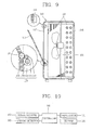
- FIG. 9 is a cross-sectional view showing an opened state of a outlet door of FIG. 8;
- FIG. 10 is a control block diagram of the outdoor unit of the air conditioner of FIG. 8;
- FIG. 11 is a flow chart for describing an operation method of the outdoor unit of the air conditioner of FIG. 8;
- FIG. 12 is a perspective view of an outdoor unit of an air conditioner according to a third embodiment of the present invention;
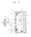
- FIG. 13 is a longitudinal sectional view of FIG. 12;
- FIG. 14 is a cross sectional view showing an opened state of an outlet door of FIG. 12; and
- FIG. 15 is a control block diagram of the outdoor unit of the air conditioner.
- Reference will now be made in detail to the preferred embodiments of the present invention, examples of which are illustrated in the accompanying drawings.
- Referring to FIGS. 3 through 6, an outdoor unit of an air conditioner according to a first embodiment of the present invention includes a
case 110 forming a receiving space therein and having anoutlet 177 at one side, and anoutdoor door 131 installed to open/dose theoutlet 117 of thecase 110. - The
case 110 is formed to have a rectangular parallelepiped shape, and includes therein adivision plate 113 dividing the inside of thecase 110. A compressor is installed in one space divided by thedivision plate 113. Aninlet 115 through which the air is introduced is formed at rear and side surfaces of the other space divided by thedivision plate 113, and anoutlet 117 through which the air is discharged is formed at a front surface thereof. Aheat exchanger 123 is disposed inside theinlet 115, and ablower 125 is installed inside theheat exchanger 123 to introduce the air through theinlet 115 and discharge the introduced air to the outside through theoutlet 117. - The
outlet 117 has a quadrangular shape, and theoutlet door 131 of a quadrangular shape is installed at theoutlet 117. Arotary shaft 132 is formed at lower portions of both sides of theoutlet door 13 so that theoutlet door 131 can be rotated downwardly and upwardly. Aprotrusion 133 protrudes rearward from one lower portion of a rear surface of theoutlet door 131, and an outletdoor driving unit 140 is installed at one side of theprotrusion 133 to open/close theoutlet door 131. - The outlet
door driving unit 140 includes theprotrusion 133 formed on theoutlet door 131, and asolenoid 143 having arod 145 that is protruded or retracted in a vertical direction. When power is applied to thesolenoid 143, therod 145 is extendingly protruded in a longitudinal direction, and when power is cut off, therod 145 is retracted into thesolenoid 143 by an elastic force of a spring provided therein. A pint portion 14 is formed at an end of therod 145, and is bent perpendicularly to be connected to theprotrusion 133. Aslot 134 of a long hole type is formed at theprotrusion 133 so that thepin portion 146 is inserted therein and makes a relative motion. - The outdoor unit of the air conditioner according to the current embodiment includes a
controller 161 controlling thesolenoid 143. Thecontroller 161 opens theoutlet 117 when an operation signal is input from an indoor unit (not shown), and closes theoutlet 117 when an operation stop signal is input. As illustrated in FIG. 7, thecontroller 161 is connected to asignal receiver 163 receiving a signal from the indoor unit, and thesolenoid 143 so as to allow electric signal transfer. - By the aforementioned structure, when an operation signal is input through the
signal receiver 163, thecontroller 161 controls thesolenoid 143 to protrude therod 145. When therod 145 is protruded, thepin portion 145 presses theprotrusion 133, and thus theoutlet door 131 is rotated downward to open theoutlet 117 as illustrated in FIG. 6. When theblower 125 is driven, the air is introduced through theinlet 115, and the introduced air is heat-exchanged while passing through theheat exchanger 123. The heat-exchanged air is discharged through theoutlet 117, and the discharged air is guided to an upper portion of a front side of thecase 110 by theoutlet door 131. When an operation stop signal is input through thesignal receiver 163, thecontroller 161 controls thesolenoid 13 to retract therod 145. When therod 145 is retracted, theprotrusion 133 and theoutlet door 131 is rotated about therotary shaft 132, thereby closing theoutlet 117 as illustrated in FIG. 5. - An outdoor unit of an air conditioner according to a second embodiment of the present invention will now be described with reference to accompanying drawings. Like reference numerals are used to like elements with the above-mentioned and illustrated elements for the convenience of description. Referring to FIGS. 8 and 9, the outdoor unit of the air conditioner according to the current embodiment includes a
case 110 forming a receiving space therein and having anoutlet 117 at one side, ablower 125 installed inside thecase 110, anoutlet door 131 installed to open/close theoutlet 117 of thecase 110, an outletdoor driving unit 170 driving theoutlet door 131, anopening detector 165 detecting opening of theoutlet 117, and acontroller 161 controlling theblower 125 and the outletdoor driving unit 170 on the basis of a detection result of theopening detector 165. - A
heat exchanger 123 is installed in thecase 110 along aninlet 115, and ablower 125 is provided inside theheat exchanger 123. - The
outlet 117 of a quadrangular shape is formed at a front surface of thecase 110, and theoutlet door 131 of a quadrangular shape is installed at theoutlet 117. Arotary shaft 132 is formed at a lower portion of both sides of theoutlet door 131 so as to allow theoutlet door 13 to be rotated upwardly and downwardly. The outletdoor driving unit 170 is installed in thecase 110 so as to rotate theoutlet door 131. - The outlet
door driving unit 170 includes adrive motor 171 disposed at one side of theoutlet door 131, adriving gear 175 coupled to arotation shaft 173 of thedrive motor 171, a drivengear 175 coupled to therotary shaft 132 of theoutlet door 131, and agear 177 rotated in mesh with thedriving gear 175 and the drivengear 176. - The
opening detector 165 is installed at theoutlet 117 in order to detect opening of theoutlet door 131. - The outdoor unit of the air conditioner includes the
controller 161 implemented as a microcomputer having a control program. Such acontroller 171 serves to introduce the air into the outdoor unit to accelerate heat exchange when an operation signal is input from an indoor unit. As illustrated in FIG. 10, thecontroller 161 is connected to asignal receiver 163, theopening detector 165, thedrive motor 171, theblower 125, and anindicator 171 indicating predetermined information including an error to the outside for electric signal transfer, - An operation method of the outdoor unit of the air conditioner according to the current embodiment will now be described with reference to FIG. 11.
- When an operation signal is input from an indoor unit through the signal receiver 163 (S10), the
controller 161 controls thedrive motor 171 to allow theoutlet door 131 to open the outlet 117 (S20). When thedrive motor 171 rotates, theoutlet door 131 is rotated downward about therotary shaft 132 by thedriving gear 175, thegear 177, and the drivengear 176, thereby opening theoutlet 117. Thereafter, theopening detector 165 detects opening of the outlet 117 (S30), and when it is detected that theoutlet 117 is opened, theblower 125 is driven (S40). When theblower 125 is driven, the air is introduced through theinlet 115, and the introduced air is heat-exchanged while passing through theheat exchanger 123, and then is discharged to the outside through theoutlet 117. The discharged air is guided in an upwardly direction of a front side of thecase 110 by theoutlet door 131 inclined frontward and downward. - When it is detected that the
outlet 117 is not opened, thecontroller 161 counts the number (Ni) of attempts to open the outlet 117 (S60). When the counted number (Ni) is the same as or smaller than a set value (Nset), thedrive motor 171 is controlled again to open the outlet 117 (S20). When the counted number (Ni) is greater than the set value (Nset) (S70), thecontroller 161 controls the indicator167 to indicate an error to the outside (S80). Also, theblower 125 is maintained at a stopped state (S90), and theoutlet door 131 is also maintained at a closed state (S100). When an operation stop signal is input from the indoor unit through the signal receiver 163 (S50), thecontroller 161 stops driving of the blower 125 (S90), and controls thedrive motor 171 to close the outlet 117 (S110). - An air conditioner according to a third embodiment of the present invention will now be described with reference to accompanying drawings.
- Referring to FIGS. 12 through 14, the outdoor unit of the air conditioner according to the current embodiment includes a
case 110 including aninlet 115 forming therein a receiving space and introducing the air, and anoutlet 117 formed at a front side to discharge the air; aheat exchanger 123 disposed toward theinlet 115 in thecase 110; ablower 125 disposed at one side of theheat exchanger 123; and anoutlet door 131 coupled to thecase 110 to be rotatable between a closing location where theoutlet door 131 closes theoutlet 117, and an opening location where theoutlet door 131 opens theoutlet 117 and is inclined downwardly so as to guide the discharged air in an upward direction. - The
case 110 has a rectangular parallelepiped shape having therein a receiving space, and adivision plate 113 dividing a space is installed in thecase 110. Acompressor 121 is received in one space divided by thedivision plate 113 to compress a refrigerant, and aninlet 115 introducing the air is formed at side and rear surfaces of the other space divided by thedivision plate 113. An outlet of a quadrangular shape is formed at a front surface of thecase 110 to discharged the introduced air. - A
heat exchanger 123 having a reverse "L" shape is installed inside theinlet 115, and ablower 125 is installed in a front region of theheat exchanger 123. Theblower 125 introduces the external air through theinlet 115, and discharges the air heat-exchanged while passing through theheat exchanger 123 to the outside through theoutlet 117. - A plurality of
outlet door 131 are rotatably installed at theoutlet 117 to open/close the outlet 116. Arotary shaft 132 protruding from both sides of thecase 110 is formed at a lower portion of both sides of each of theoutlet door 131. A outletdoor driving unit 180 is provided at one side of therotary shaft 132 so as to open/close each of theoutlet door 131 in a rotating manner. - The outlet
door driving unit 180 includes a transmittingmember 183 disposed at one side of a rear surface of each of theoutlet door 131 to be slidable in a vertical direction, aprotrusion 133 protruding from one side of therotary shaft 132 of theoutlet door 131 toward the transmittingmember 183 perpendicularly to a plate surface of each of theoutlet doors 131, and a transmittingmember driving unit 191 driving the transmittingmember 183 to allow each of theoutlet door 131 to be driven between the closing location where each of theoutlet doors 131 closes theoutlet 117 and the opening location where each of theoutlet doors 131 opens theoutlet 117 to guide the air being discharged in an upward direction of the front side of thecase 110. - The transmitting
member driving unit 191 includes arack part 185 formed at the transmittingmember 183, apinion 193 rotated in mesh with therack part 183, and adrive motor 195 rotating thepinion 183 in forward and backward rotations. - Each
protrusion 133 has apin 135 protruding outwardly parallel to therotary shaft 132, and the transmittingmember 183 includes aslot 184 formed corresponding to a rotation path of thepin 135 so that eachpin 135 can be received therein to make a relative motion. - Transmitting member guides 187 are provided at both sides of the transmitting
member 183 to guide sliding of the transmittingmember 183 in a vertical direction. - The
controller 161 implemented as a microprocessor having a control program is connected to asignal receiver 163 receiving a signal from an indoor unit (not shown), theblower 125, and thedrive motor 195 for electric signal transfer, so that when an operation is started, thecontroller 161 can perform control allowing theoutlet 117 to be opened/closed, while driving theblower 125. - By the structure, when the
signal receiver 163 receives a cooling or heating operation signal, thecontroller 161 rotates theblower 125, and also drives thedrive motor 195 to rotate theoutlet door 131 in a direction in which theoutlet 117 is opened. When power is applied to thedrive motor 195 and thus rotation is started, thepinion 193 is rotated. Thus, the transmittingmember 183 having therack part 185 engaged with thepinion 193 is slide upwardly. Then, each of theoutlet door 131 is rotated downwardly about the center of therotary shaft 132, and thus is inclined at the opening location. - When the
blower 125 is rotated, the air is introduced into thecase 110 through theinlet 115. The introduced air is heat-exchanged while passing through theheat exchanger 123, and then is discharged through theoutlet 117. Here, the air is discharged in an upward direction of a front side of thecase 110 by each of theoutlet door 131 inclined at the opening location. - When an operation stop signal of the indoor unit is received through the
signal receiver 163, thecontroller 161 serves to stop theblower 125, and control thedrive motor 195 to close theoutlet 117. - Operational effects of the outdoor unit of the air conditioner and the operation method according to the present invention will now be described.
- An outdoor unit of an air conditioner according to the present invention includes an outlet door opening/closing an outlet, such that the outlet is opened at the time of operation to thus guide the air being discharged in a desired direction, and the outlet is closed when the operation is stopped to thus prevent foreign substances from flowing into a case.
- Accordingly, when the outlet is installed toward a sidewalk, the air heat-exchanged with the heat exchanger is guided away from a pedestrian, thereby preventing unpleasantness of the pedestrian.
- Also, when the outlet is closed, the closing of the outlet is immediately detected, so that the operation of drive elements including a blower is not started. Accordingly, the device can be prevented from being operated under abnormal conditions, and this abnormal conditions can be indicated to the outside, so that the quick action for such abnormality can be made.
- As the present invention may be embodied in several forms without departing from the spirit or essential characteristics thereof, it should also be understood that the above-described embodiments are not limited by any of the details of the foregoing description, unless otherwise specified, but rather should be construed broadly within its spirit and scope as defined in the appended claims, and therefore all changes and modifications that fall within the metes and bounds of the claims, or equivalents of such metes and bounds are therefore intended to be embraced by the appended claims.
Claims (11)
- An outdoor unit of an air conditioner comprising:a case including an outlet; andan outlet door installed at the case to open/dose the outlet, and guiding the air being discharged when opened.
- The outdoor unit of claim 1, further comprising an outlet door driving unit driving the outlet door to open/close the outlet.
- The outdoor unit of claim 1 or 2, wherein the outlet door is installed to be rotatable upwardly and downwardly about a lower end, and is inclined downwardly so as to guide the air in an upward direction when opened.
- The outdoor unit of claim 2 or 3, wherein the outlet door driving unit comprises a solenoid.
- The outdoor unit of claim 2 or 3, wherein the outlet door driving unit comprises a drive motor.
- The outdoor unit of any of claims 2 to 5, wherein the outlet door is configured in plurality, and
the outlet door driving unit comprises a transmitting member connected to the outlet door to simultaneously interwork therewith, and a transmitting member driving unit driving the transmitting member. - The outdoor unit of any of claims 2 to 6, further comprising:an opening detector detecting opening of the outlet; anda controller controlling the outlet door driving unit and the blower on the basis of a detection result of the opening detector.
- The outdoor unit of claim 7, wherein the case includes a blower therein, and the controller controls the blower on the basis of a detection result of the opening detector.
- A method of operating an outdoor unit of an air conditioner comprising a case having an outlet, a blower disposed in the case, an outlet door opening/closing the outlet, and an outlet door driving unit driving the outlet door, the method comprising:controlling the outlet door driving unit to open the outlet; anddriving the blower.
- The method of claim 9, wherein the outdoor unit further comprises an opening detector,
the method further comprising detecting opening of the outlet by the opening detector before the driving of the blower,
wherein in the driving of the blower, the blower is driven when the outlet is opened, and the blower is stopped when the outlet is closed. - The method of claim 10, wherein the outdoor unit further comprises an indicator indicating information including error to the outside,
the method further comprising controlling the indicator to indicate an error the outside in a state where the blower is stopped when the outlet is closed, after the detecting of the opening of the outlet.
Applications Claiming Priority (1)
| Application Number | Priority Date | Filing Date | Title |
|---|---|---|---|
| KR1020050134473A KR100724389B1 (en) | 2005-12-29 | 2005-12-29 | Outdoor unit of air conditioner with discharge door |
Publications (1)
| Publication Number | Publication Date |
|---|---|
| EP1804003A1 true EP1804003A1 (en) | 2007-07-04 |
Family
ID=37891999
Family Applications (1)
| Application Number | Title | Priority Date | Filing Date |
|---|---|---|---|
| EP06127273A Withdrawn EP1804003A1 (en) | 2005-12-29 | 2006-12-28 | Outdoor unit for air conditioner and operation method thereof |
Country Status (4)
| Country | Link |
|---|---|
| US (1) | US20070151286A1 (en) |
| EP (1) | EP1804003A1 (en) |
| KR (1) | KR100724389B1 (en) |
| CA (1) | CA2572696A1 (en) |
Cited By (6)
| Publication number | Priority date | Publication date | Assignee | Title |
|---|---|---|---|---|
| EP2246635A4 (en) * | 2008-01-08 | 2014-12-10 | Daikin Ind Ltd | AIR FLOW DIRECTION ADJUSTMENT UNIT AND HEAT SOURCE UNIT FOR REFRIGERATION DEVICE |
| CN106568124A (en) * | 2016-10-21 | 2017-04-19 | 珠海格力电器股份有限公司 | Air conditioner |
| CN107327931A (en) * | 2017-07-31 | 2017-11-07 | 广东美的制冷设备有限公司 | air conditioner indoor unit |
| CN108592246A (en) * | 2018-04-27 | 2018-09-28 | 珠海格力电器股份有限公司 | Outdoor unit, air conditioner, and control method for the outdoor unit |
| WO2019024549A1 (en) * | 2017-07-31 | 2019-02-07 | 广东美的制冷设备有限公司 | Indoor air-conditioning unit |
| CN111578393A (en) * | 2020-04-30 | 2020-08-25 | 青岛海尔空调器有限总公司 | A protector, off-premises station for off-premises station |
Families Citing this family (10)
| Publication number | Priority date | Publication date | Assignee | Title |
|---|---|---|---|---|
| KR101216229B1 (en) | 2010-10-14 | 2012-12-28 | 이호진 | protecting device for a compressor of a heat pump |
| CN202470348U (en) * | 2012-02-29 | 2012-10-03 | 珠海格力电器股份有限公司 | Wind deflector driving device and air conditioner indoor unit using the driving device |
| KR102040800B1 (en) * | 2013-04-11 | 2019-12-05 | 삼성전자주식회사 | Blade assembly and air conditioner having the same |
| JP6099558B2 (en) * | 2013-12-27 | 2017-03-22 | 三菱電機株式会社 | Outdoor unit |
| CN104359164B (en) * | 2014-10-17 | 2018-06-01 | 广东美的制冷设备有限公司 | Air-conditioner outdoor unit and its control method |
| CN104896583A (en) * | 2015-05-12 | 2015-09-09 | 广东美的制冷设备有限公司 | Air conditioner and control method of air conditioner |
| KR101583603B1 (en) * | 2015-07-17 | 2016-01-12 | 세연기업 주식회사 | Hybrid Heat pump system |
| JP7223256B2 (en) * | 2018-12-27 | 2023-02-16 | 株式会社富士通ゼネラル | air conditioner |
| WO2025059693A1 (en) * | 2023-10-23 | 2025-03-20 | Schlumberger Technology Corporation | Dual source heat pump system |
| US12474079B2 (en) | 2023-10-23 | 2025-11-18 | Schlumberger Technology Corporation | Thermal system with exhaust heat exchanger |
Citations (6)
| Publication number | Priority date | Publication date | Assignee | Title |
|---|---|---|---|---|
| US3148514A (en) * | 1963-04-15 | 1964-09-15 | Mccray Refrigerator Company In | Housings for condensers of refrigerator systems |
| US3584466A (en) * | 1969-04-01 | 1971-06-15 | Elsters | Refrigerator-compressor system with wet weather adjustment |
| JPH08247502A (en) * | 1995-03-13 | 1996-09-27 | Daikin Ind Ltd | Outdoor unit of refrigeration equipment |
| US6196010B1 (en) * | 1998-06-03 | 2001-03-06 | John Harry Mohrman | Temperature control zone for compressor/condenser air intake |
| JP2001174001A (en) * | 1999-12-20 | 2001-06-29 | Chofu Seisakusho Co Ltd | Air conditioner |
| WO2004097307A1 (en) * | 2003-04-30 | 2004-11-11 | Lg Electronics, Inc. | Apparatus for controlling outdoor unit’s louver blades and its method |
Family Cites Families (7)
| Publication number | Priority date | Publication date | Assignee | Title |
|---|---|---|---|---|
| US3431748A (en) * | 1967-09-15 | 1969-03-11 | Carrier Corp | Door mounting for a room air conditioner discharge opening |
| JPH05288368A (en) * | 1992-04-07 | 1993-11-02 | Mitsubishi Heavy Ind Ltd | Outdoor unit for air conditioner |
| KR0132997B1 (en) * | 1994-08-20 | 1998-04-21 | 김광호 | Outlet machine of airconditioner |
| KR0182588B1 (en) * | 1996-09-03 | 1999-05-01 | 김광호 | Opening and closing control device of air conditioner and its method |
| JP2000161715A (en) * | 1998-11-30 | 2000-06-16 | Daikin Ind Ltd | Outdoor units and air conditioners |
| WO2002103248A2 (en) * | 2001-06-19 | 2002-12-27 | Lg Electronics Inc. | Air conditioner |
| KR200401833Y1 (en) | 2005-09-14 | 2005-11-22 | 위니아만도 주식회사 | Outdoor device of separation type air conditioner |
-
2005
- 2005-12-29 KR KR1020050134473A patent/KR100724389B1/en not_active Expired - Fee Related
-
2006
- 2006-12-27 US US11/645,540 patent/US20070151286A1/en not_active Abandoned
- 2006-12-28 EP EP06127273A patent/EP1804003A1/en not_active Withdrawn
- 2006-12-29 CA CA002572696A patent/CA2572696A1/en not_active Abandoned
Patent Citations (6)
| Publication number | Priority date | Publication date | Assignee | Title |
|---|---|---|---|---|
| US3148514A (en) * | 1963-04-15 | 1964-09-15 | Mccray Refrigerator Company In | Housings for condensers of refrigerator systems |
| US3584466A (en) * | 1969-04-01 | 1971-06-15 | Elsters | Refrigerator-compressor system with wet weather adjustment |
| JPH08247502A (en) * | 1995-03-13 | 1996-09-27 | Daikin Ind Ltd | Outdoor unit of refrigeration equipment |
| US6196010B1 (en) * | 1998-06-03 | 2001-03-06 | John Harry Mohrman | Temperature control zone for compressor/condenser air intake |
| JP2001174001A (en) * | 1999-12-20 | 2001-06-29 | Chofu Seisakusho Co Ltd | Air conditioner |
| WO2004097307A1 (en) * | 2003-04-30 | 2004-11-11 | Lg Electronics, Inc. | Apparatus for controlling outdoor unit’s louver blades and its method |
Cited By (9)
| Publication number | Priority date | Publication date | Assignee | Title |
|---|---|---|---|---|
| EP2246635A4 (en) * | 2008-01-08 | 2014-12-10 | Daikin Ind Ltd | AIR FLOW DIRECTION ADJUSTMENT UNIT AND HEAT SOURCE UNIT FOR REFRIGERATION DEVICE |
| CN106568124A (en) * | 2016-10-21 | 2017-04-19 | 珠海格力电器股份有限公司 | Air conditioner |
| CN107327931A (en) * | 2017-07-31 | 2017-11-07 | 广东美的制冷设备有限公司 | air conditioner indoor unit |
| WO2019024549A1 (en) * | 2017-07-31 | 2019-02-07 | 广东美的制冷设备有限公司 | Indoor air-conditioning unit |
| CN107327931B (en) * | 2017-07-31 | 2020-06-26 | 广东美的制冷设备有限公司 | Air conditioner indoor unit |
| US11913650B2 (en) | 2017-07-31 | 2024-02-27 | Gd Midea Air-Conditioning Equipment Co., Ltd. | Air conditioner indoor unit |
| CN108592246A (en) * | 2018-04-27 | 2018-09-28 | 珠海格力电器股份有限公司 | Outdoor unit, air conditioner, and control method for the outdoor unit |
| CN108592246B (en) * | 2018-04-27 | 2019-12-17 | 珠海格力电器股份有限公司 | Outdoor unit, air conditioner, and control method for the outdoor unit |
| CN111578393A (en) * | 2020-04-30 | 2020-08-25 | 青岛海尔空调器有限总公司 | A protector, off-premises station for off-premises station |
Also Published As
| Publication number | Publication date |
|---|---|
| US20070151286A1 (en) | 2007-07-05 |
| CA2572696A1 (en) | 2007-06-29 |
| KR100724389B1 (en) | 2007-06-04 |
Similar Documents
| Publication | Publication Date | Title |
|---|---|---|
| EP1804003A1 (en) | Outdoor unit for air conditioner and operation method thereof | |
| CN101688680B (en) | Air conditioning apparatus | |
| US5787717A (en) | Suction inlet/discharge outlet opening and closing apparatus for an air conditioner and method therefor | |
| JP3194896B2 (en) | Opening / closing control apparatus and method for air conditioner | |
| CN112880046A (en) | Auxiliary cleaning device, cleaning method and integral air conditioner | |
| JP3653634B2 (en) | Shutter drive device for indoor unit of packaged air conditioner | |
| CN110785611B (en) | Air conditioner | |
| CN105202625B (en) | Vertical air conditioner indoor unit | |
| JPH1082546A (en) | Operation control device and method for air conditioner | |
| KR100722276B1 (en) | Air conditioner and its noise control method | |
| KR100810849B1 (en) | Air driving device and method of louver blade for outdoor unit | |
| KR20030041926A (en) | Opening and shutting testing apparatus and its method for outdoor unit's louver blade | |
| CN108332379B (en) | Air conditioner, control method and control device thereof, and storage medium | |
| KR100231025B1 (en) | Apparatus and method for controlling operation of an air conditioner | |
| KR100554281B1 (en) | Louver control method of air conditioner and air conditioner | |
| KR100585411B1 (en) | Stop position detection structure of Auto Shutter for air conditioner | |
| WO2022064764A1 (en) | Floor-type air conditioner | |
| CN213019954U (en) | Cabinet air conditioner | |
| KR100289126B1 (en) | Indoor Room for Air Conditioning Equipment | |
| CN212841925U (en) | Outdoor unit and air conditioner | |
| KR20000000745U (en) | Indoor unit for air conditioner | |
| KR100324140B1 (en) | Suction grill opening detection device of air conditioner | |
| KR100634294B1 (en) | Cold air inflow prevention structure by auto shutter of air conditioner | |
| KR100624107B1 (en) | Reinforcing bar revolving structure of auto shutter for air conditioner | |
| JP2025062208A (en) | Air conditioning equipment |
Legal Events
| Date | Code | Title | Description |
|---|---|---|---|
| PUAI | Public reference made under article 153(3) epc to a published international application that has entered the european phase |
Free format text: ORIGINAL CODE: 0009012 |
|
| 17P | Request for examination filed |
Effective date: 20070126 |
|
| AK | Designated contracting states |
Kind code of ref document: A1 Designated state(s): AT BE BG CH CY CZ DE DK EE ES FI FR GB GR HU IE IS IT LI LT LU LV MC NL PL PT RO SE SI SK TR |
|
| AX | Request for extension of the european patent |
Extension state: AL BA HR MK YU |
|
| AKX | Designation fees paid |
Designated state(s): DE FR GB IT |
|
| STAA | Information on the status of an ep patent application or granted ep patent |
Free format text: STATUS: THE APPLICATION IS DEEMED TO BE WITHDRAWN |
|
| 18D | Application deemed to be withdrawn |
Effective date: 20080110 |