EP1803998A1 - Gas shutoff apparatus and gas shutoff method - Google Patents
Gas shutoff apparatus and gas shutoff method Download PDFInfo
- Publication number
- EP1803998A1 EP1803998A1 EP05795850A EP05795850A EP1803998A1 EP 1803998 A1 EP1803998 A1 EP 1803998A1 EP 05795850 A EP05795850 A EP 05795850A EP 05795850 A EP05795850 A EP 05795850A EP 1803998 A1 EP1803998 A1 EP 1803998A1
- Authority
- EP
- European Patent Office
- Prior art keywords
- unit
- flow volume
- pressure
- return
- shutoff
- Prior art date
- Legal status (The legal status is an assumption and is not a legal conclusion. Google has not performed a legal analysis and makes no representation as to the accuracy of the status listed.)
- Granted
Links
Images


Classifications
-
- G—PHYSICS
- G01—MEASURING; TESTING
- G01F—MEASURING VOLUME, VOLUME FLOW, MASS FLOW OR LIQUID LEVEL; METERING BY VOLUME
- G01F1/00—Measuring the volume flow or mass flow of fluid or fluent solid material wherein the fluid passes through a meter in a continuous flow
- G01F1/66—Measuring the volume flow or mass flow of fluid or fluent solid material wherein the fluid passes through a meter in a continuous flow by measuring frequency, phase shift or propagation time of electromagnetic or other waves, e.g. using ultrasonic flowmeters
- G01F1/667—Arrangements of transducers for ultrasonic flowmeters; Circuits for operating ultrasonic flowmeters
-
- F—MECHANICAL ENGINEERING; LIGHTING; HEATING; WEAPONS; BLASTING
- F23—COMBUSTION APPARATUS; COMBUSTION PROCESSES
- F23N—REGULATING OR CONTROLLING COMBUSTION
- F23N5/00—Systems for controlling combustion
- F23N5/24—Preventing development of abnormal or undesired conditions, i.e. safety arrangements
-
- F—MECHANICAL ENGINEERING; LIGHTING; HEATING; WEAPONS; BLASTING
- F23—COMBUSTION APPARATUS; COMBUSTION PROCESSES
- F23K—FEEDING FUEL TO COMBUSTION APPARATUS
- F23K5/00—Feeding or distributing other fuel to combustion apparatus
-
- F—MECHANICAL ENGINEERING; LIGHTING; HEATING; WEAPONS; BLASTING
- F23—COMBUSTION APPARATUS; COMBUSTION PROCESSES
- F23N—REGULATING OR CONTROLLING COMBUSTION
- F23N1/00—Regulating fuel supply
-
- F—MECHANICAL ENGINEERING; LIGHTING; HEATING; WEAPONS; BLASTING
- F23—COMBUSTION APPARATUS; COMBUSTION PROCESSES
- F23N—REGULATING OR CONTROLLING COMBUSTION
- F23N5/00—Systems for controlling combustion
- F23N5/24—Preventing development of abnormal or undesired conditions, i.e. safety arrangements
- F23N5/242—Preventing development of abnormal or undesired conditions, i.e. safety arrangements using electronic means
-
- G—PHYSICS
- G01—MEASURING; TESTING
- G01F—MEASURING VOLUME, VOLUME FLOW, MASS FLOW OR LIQUID LEVEL; METERING BY VOLUME
- G01F3/00—Measuring the volume flow of fluids or fluent solid material wherein the fluid passes through the meter in successive and more or less isolated quantities, the meter being driven by the flow
- G01F3/02—Measuring the volume flow of fluids or fluent solid material wherein the fluid passes through the meter in successive and more or less isolated quantities, the meter being driven by the flow with measuring chambers which expand or contract during measurement
- G01F3/20—Measuring the volume flow of fluids or fluent solid material wherein the fluid passes through the meter in successive and more or less isolated quantities, the meter being driven by the flow with measuring chambers which expand or contract during measurement having flexible movable walls, e.g. diaphragms, bellows
- G01F3/22—Measuring the volume flow of fluids or fluent solid material wherein the fluid passes through the meter in successive and more or less isolated quantities, the meter being driven by the flow with measuring chambers which expand or contract during measurement having flexible movable walls, e.g. diaphragms, bellows for gases
-
- G—PHYSICS
- G01—MEASURING; TESTING
- G01M—TESTING STATIC OR DYNAMIC BALANCE OF MACHINES OR STRUCTURES; TESTING OF STRUCTURES OR APPARATUS, NOT OTHERWISE PROVIDED FOR
- G01M3/00—Investigating fluid-tightness of structures
- G01M3/02—Investigating fluid-tightness of structures by using fluid or vacuum
- G01M3/04—Investigating fluid-tightness of structures by using fluid or vacuum by detecting the presence of fluid at the leakage point
- G01M3/24—Investigating fluid-tightness of structures by using fluid or vacuum by detecting the presence of fluid at the leakage point using infrasonic, sonic, or ultrasonic vibrations
- G01M3/243—Investigating fluid-tightness of structures by using fluid or vacuum by detecting the presence of fluid at the leakage point using infrasonic, sonic, or ultrasonic vibrations for pipes
-
- G—PHYSICS
- G01—MEASURING; TESTING
- G01M—TESTING STATIC OR DYNAMIC BALANCE OF MACHINES OR STRUCTURES; TESTING OF STRUCTURES OR APPARATUS, NOT OTHERWISE PROVIDED FOR
- G01M3/00—Investigating fluid-tightness of structures
- G01M3/02—Investigating fluid-tightness of structures by using fluid or vacuum
- G01M3/26—Investigating fluid-tightness of structures by using fluid or vacuum by measuring rate of loss or gain of fluid, e.g. by pressure-responsive devices, by flow detectors
- G01M3/28—Investigating fluid-tightness of structures by using fluid or vacuum by measuring rate of loss or gain of fluid, e.g. by pressure-responsive devices, by flow detectors for pipes, cables or tubes; for pipe joints or seals; for valves ; for welds
- G01M3/2807—Investigating fluid-tightness of structures by using fluid or vacuum by measuring rate of loss or gain of fluid, e.g. by pressure-responsive devices, by flow detectors for pipes, cables or tubes; for pipe joints or seals; for valves ; for welds for pipes
-
- F—MECHANICAL ENGINEERING; LIGHTING; HEATING; WEAPONS; BLASTING
- F23—COMBUSTION APPARATUS; COMBUSTION PROCESSES
- F23N—REGULATING OR CONTROLLING COMBUSTION
- F23N2231/00—Fail safe
- F23N2231/18—Detecting fluid leaks
-
- Y—GENERAL TAGGING OF NEW TECHNOLOGICAL DEVELOPMENTS; GENERAL TAGGING OF CROSS-SECTIONAL TECHNOLOGIES SPANNING OVER SEVERAL SECTIONS OF THE IPC; TECHNICAL SUBJECTS COVERED BY FORMER USPC CROSS-REFERENCE ART COLLECTIONS [XRACs] AND DIGESTS
- Y10—TECHNICAL SUBJECTS COVERED BY FORMER USPC
- Y10T—TECHNICAL SUBJECTS COVERED BY FORMER US CLASSIFICATION
- Y10T137/00—Fluid handling
- Y10T137/0318—Processes
- Y10T137/0324—With control of flow by a condition or characteristic of a fluid
- Y10T137/0379—By fluid pressure
-
- Y—GENERAL TAGGING OF NEW TECHNOLOGICAL DEVELOPMENTS; GENERAL TAGGING OF CROSS-SECTIONAL TECHNOLOGIES SPANNING OVER SEVERAL SECTIONS OF THE IPC; TECHNICAL SUBJECTS COVERED BY FORMER USPC CROSS-REFERENCE ART COLLECTIONS [XRACs] AND DIGESTS
- Y10—TECHNICAL SUBJECTS COVERED BY FORMER USPC
- Y10T—TECHNICAL SUBJECTS COVERED BY FORMER US CLASSIFICATION
- Y10T137/00—Fluid handling
- Y10T137/7722—Line condition change responsive valves
- Y10T137/7723—Safety cut-off requiring reset
- Y10T137/7726—Responsive to change in rate of flow
-
- Y—GENERAL TAGGING OF NEW TECHNOLOGICAL DEVELOPMENTS; GENERAL TAGGING OF CROSS-SECTIONAL TECHNOLOGIES SPANNING OVER SEVERAL SECTIONS OF THE IPC; TECHNICAL SUBJECTS COVERED BY FORMER USPC CROSS-REFERENCE ART COLLECTIONS [XRACs] AND DIGESTS
- Y10—TECHNICAL SUBJECTS COVERED BY FORMER USPC
- Y10T—TECHNICAL SUBJECTS COVERED BY FORMER US CLASSIFICATION
- Y10T137/00—Fluid handling
- Y10T137/7722—Line condition change responsive valves
- Y10T137/7758—Pilot or servo controlled
- Y10T137/7761—Electrically actuated valve
-
- Y—GENERAL TAGGING OF NEW TECHNOLOGICAL DEVELOPMENTS; GENERAL TAGGING OF CROSS-SECTIONAL TECHNOLOGIES SPANNING OVER SEVERAL SECTIONS OF THE IPC; TECHNICAL SUBJECTS COVERED BY FORMER USPC CROSS-REFERENCE ART COLLECTIONS [XRACs] AND DIGESTS
- Y10—TECHNICAL SUBJECTS COVERED BY FORMER USPC
- Y10T—TECHNICAL SUBJECTS COVERED BY FORMER US CLASSIFICATION
- Y10T137/00—Fluid handling
- Y10T137/8593—Systems
- Y10T137/86389—Programmer or timer
- Y10T137/86397—With independent valve controller
-
- Y—GENERAL TAGGING OF NEW TECHNOLOGICAL DEVELOPMENTS; GENERAL TAGGING OF CROSS-SECTIONAL TECHNOLOGIES SPANNING OVER SEVERAL SECTIONS OF THE IPC; TECHNICAL SUBJECTS COVERED BY FORMER USPC CROSS-REFERENCE ART COLLECTIONS [XRACs] AND DIGESTS
- Y10—TECHNICAL SUBJECTS COVERED BY FORMER USPC
- Y10T—TECHNICAL SUBJECTS COVERED BY FORMER US CLASSIFICATION
- Y10T137/00—Fluid handling
- Y10T137/8593—Systems
- Y10T137/86389—Programmer or timer
- Y10T137/86405—Repeating cycle
- Y10T137/86421—Variable
Definitions
- the present invention relates to a gas shutoff apparatus and a gas shutoff method for detecting flow rates of various medium including gases such as a city gas or an LP gas, flowing though a pipe, by using ultrasound and accurately measuring a medium use amount in order to monitor whether or not its use condition is safe.
- gases such as a city gas or an LP gas
- Fig. 9 shows a conventional gas shutoff apparatus of the above type as disclosed in, for example, JP-A-56-160520 .
- a reference numeral 1 denotes a pipe, in which a shutoff valve 3 for shutting off or passing use gases in the pipe is installed near a gas supply source 2.
- a reference numeral 4 denotes gas exhaust equipment such as a gas stove, in which an equipment plug 5 is installed.
- a reference numeral 6 denotes a main controller, which transmits a control signal to the shutoff valve.
- a reference numeral 7 denotes a pressure sensor unit, which is installed in downstream of the shutoff valve 3.
- a reference numeral 8 denotes an equipment plug open/close detection unit, which outputs an equipment plug open/close signal in association with open/close operations of the equipment plug 5.
- a reference numeral 9 denotes a use gas pressure monitoring circuit
- a reference numeral 10 denotes a residual gas pressure detection circuit.
- a reference numeral 11 denotes a storing circuit, which stores the gas pressure signal from the use gas pressure detection circuit 9 and the residual gas pressure detection circuit 10.
- a reference signal 12 denotes a shutoff valve open/close circuit, which receives a reduction condition and outputs a blockage signal to the shutoff valve 14 when a pressure reduction signal is input from the use gas pressure detection circuit 9 and the residual gas pressure detection circuit 10 to the storing circuit 11.
- a reference numeral 13 denotes a return button
- a reference numeral 14 denotes a timer circuit
- a reference numeral 15 denotes a safety return circuit, which transmits an output signal from the storing circuit 11 and the timer circuit 12 to the storing circuit 11, the timer circuit 12, and a lamp buzzer circuit 16 when the output signal from the storing circuit 11 and the timer circuit 12 is received, in order to retain a checking condition.
- an equipment plug open/close signal is output from the equipment plug open/close detection unit 8 to the use gas pressure monitoring circuit 9 and the residual gas pressure detection circuit 10.
- the gas pressure detection signal from the pressure detection unit 7 is input to the use gas pressure monitoring circuit 9 and the residual gas pressure detection circuit 10.
- the use gas pressure monitoring circuit 9 outputs the gas pressure detection signal and the equipment plug open/close signal, which have been input, to the storing circuit 11.
- the gas is output to the shutoff valve open/close circuit 12.
- the input signals such as the equipment plug open/close signal and the gas pressure detection signal to the residual gas pressure detection circuit 10 are output to storing circuit 11 in order to detect an abnormal condition.
- the output signal from the equipment plug open/close unit 8 is output to each circuit, and the residual gas detection circuit 10 is set when the equipment plug 5 is closed.
- the residual gas pressure detection circuit 10 starts to detect the residual gas pressure when the equipment plug 5 is closed.
- the storing circuit 11 and the safety return circuit 15 transmits signals to the shutoff valve open/close circuit 12 and the timer circuit 14 to start the timer as well as set the shutoff valve 3 to an open state.
- the timer circuit 14 it is monitored again whether or not the residual gas pressure is reduced below a certain value within a certain time limit (e.g., within five to fifteen minutes) set by the timer circuit 14.
- a signal is transmitted to the storing circuit 11 and the shutoff valve 3 is locked through the shutoff valve open/close circuit 12.
- the storing circuit 11 is reset.
- the storing circuit 11 stores a gas pressure reduction signal from the use gas pressure monitoring circuit 9 or the residual gas pressure detection circuit 10, and outputs it to the shutoff valve open/close circuit 12 to close the shutoff valve 3.
- the signal from the use gas pressure monitoring circuit 9 is output to the lamp buzzer circuit 16 through the timer circuit 14 and the safety return circuit 15 in order to operate a buzzer or an alarming lamp.
- the shutoff valve open/close circuit 12 receives a signal from the storing circuit 11, which has received the signal from the residual gas pressure detection circuit 10, to stop electric transmission to the shutoff valve 3 in the case of an abnormal signal.
- the timer circuit 14 is operated on the basis of operation of the storing circuit 11, the safety return circuit 15, or the return button 13, and transmits its output to the lamp buzzer circuit 16 and the safety return circuit 5.
- the safety return circuit 15 receives the outputs from the storing circuit 11 and the timer circuit 14, and transmits a signal to the lamp buzzer circuit 16, to retain a checking condition.
- the present invention is contrived to solve the aforementioned problems, and has an object to provide a gas shutoff apparatus for rapidly performing gas leakage determination on whether or not there is use of gases such as a city gas and an LP gas when the gas shutoff apparatus is operated and then returned, in order to monitor whether of not a use condition of gas equipment is safe.
- the present invention has an object to provide a gas shutoff apparatus for rapidly and certainly performing gas leakage determination on whether or not gases such as a city gas or an LP gas are minutely leaked due to unstable locking of an original plug of the equipment when the gas shutoff apparatus performs a shutoff operation and then is returned to an initial state, in order to monitor whether or not a use condition of the gas equipment is safe.
- a use condition of gas equipment is monitored.
- An abnormality determination unit determines whether or not a use flow volume obtained by detecting a flow velocity obtained by measuring a signal transfer time in a medium using a flow volume detection return unit and converting the detected flow velocity into a flow volume using a flow volume calculation unit.
- a return signal is output from a return unit to a shutoff unit in order to use the gas again by opening the fluid path.
- a return time-counting unit starts the time-counting operation, and then, a predetermined time period has been elapsed
- whether or not a predetermined flow volume or greater flows is determined using the flow volume calculation unit in order to identify whether or not all of the gas plugs of the gas equipment connected to the downstream of the gas shutoff apparatus are closed.
- the leakage determination unit determines that there is leakage, and a driving signal is output to the shutoff unit to close the fluid path.
- the gas shutoff apparatus shuts off the fluid path, and then the return unit drives the shutoff unit in order to open the fluid path and use the gas again, whether or not the gas equipment can be used again or whether or not the gas leaks can be rapidly determined.
- the gas leaks it is possible to immediately shutoff the gas. Also, it is possible to accurately determine whether or not there is leakage, or whether or not the gas equipment is recovered to a normal setup condition.
- the use condition can be monitored, it does not take a long time to determine leakage in a leakage condition. Therefore, it is possible to prevent leakage of raw gases in a short time.
- a use condition of gas equipment is monitored.
- An abnormality determination unit determines whether or not a use flow volume obtained by detecting a flow velocity obtained by measuring a signal transfer time in a medium using a flow volume detection return unit and converting the detected flow velocity into a flow volume using a flow volume calculation unit.
- a return signal is output from a return unit to a shutoff unit in order to use the gas again by opening the fluid path.
- the leakage determination unit detects that the pressure in the pipe is reduced to a predetermined pressure or lower using a pressure detection unit which detects the pressure in the fluid path in order to identify whether or not all of the gas plugs of the gas equipment connected to the downstream of the gas shutoff apparatus are closed, a driving signal is output to the shutoff unit to close the fluid path.
- the gas shutoff apparatus shuts off the fluid path, and then the return unit drives the shutoff unit in order to open the fluid path and use the gas again, whether or not the gas equipment can be used again or whether or not the gas leaks can be rapidly determined by identifying whether or not the supply pressure is reduced.
- the gas leaks it is possible to immediately shutoff the gas. Also, it is possible to accurately determine whether or not there is leakage, or whether or not the gas equipment is recovered to a normal setup condition.
- the use condition can be monitored, it does not take a long time to determine leakage in a leakage condition. Therefore, it is possible to prevent leakage of raw gases in a short time.
- the shutoff unit close the fluid path, and then, the shutoff unit is recovered using return unit. Since gases leaks after the shutoff, the gas pressure is reduced.
- the pipe length from the gas shutoff apparatus to the gas equipment is filled with gases, although the time for determining leakage is different depending on the pipe length through which the fluid flows, the leakage determination is performed on the basis of the flow volume obtained from the flow velocity detection unit without erroneously determining the flow volume measured when the pipe is filled with gases as the leakage.
- the shutoff unit close the fluid path, and then, the shutoff unit is recovered using return unit. Since gases leaks after the shutoff, the gas pressure is reduced.
- the pipe length from the gas shutoff apparatus to the gas equipment is filled with gases. The time for determining leakage is different depending on the pipe length through which the fluid flows. The supply pressure becomes safe as a blockage pressure when the pipe is filled with gases, and the all of the corks of the equipment in the downstream are closed.
- the supply pressure is reduced from the blockage pressure to the control pressure. Therefore, the leakage determination is performed on the basis of the pressure obtained from the pressure detection unit without erroneously determining the flow volume measured when the pipe is opened. As a result, it is possible to determine, in a short time, whether or not the gas equipment can be used again. In addition, it is possible to identify, in a short time, removal of the cause of the shutoff or whether or not the original cork of the gas equipment is perfectly closed, when the erroneous determination is performed due to an abnormally large flow volume, a total flow volume shutoff, or a use time shutoff, Therefore, convenience and safety can be improved.
- a gas shutoff apparatus comprising: a flow velocity detection unit for detecting a flow velocity by measuring a signal transfer time in a medium; a flow volume calculation unit for converting the flow velocity detected by the flow velocity detection unit into a flow volume; an abnormality determination unit for determining whether or not the use flow volume obtained by the flow volume calculation unit is normal; a shutoff unit for shutting off a fluid path when the abnormal determination unit determines that there is abnormality; a return unit for outputting a return signal to the shutoff unit in order to open the fluid path; a return time-counting unit for starting a time-counting using a return unit; a leakage determination unit for outputting a driving signal to the shutoff unit to shutoff the a fluid path when it is detected that the flow volume obtained by the flow volume calculation unit is equal to or larger than a predetermined flow volume after the return time-counting unit determines that a predetermined time has been elapsed.
- the return unit drives the shutoff unit to open the fluid path.
- the gas in the pipe is leaked, and the gas pressure is reduced until the equipment plug is closed after the shutoff.
- the return operation is performed, and then, the gas is filled in the pipe, a large amount of flux initially flows, and the flow volume is reduced after the pipe is fully filled with the gases.
- the return time-counting unit counts timings, leakage determination based on the flow volume detected by the flow velocity detection unit can be delayed.
- the gas shutoff apparatus comprises: a flow velocity detection unit for detecting a flow velocity by measuring a signal transfer time in a medium; a flow volume calculation unit for converting the flow velocity detected by the flow velocity detection unit into a flow volume; an abnormality determination unit for detecting whether or not the use flow volume obtained by the flow volume calculation unit is normal; a shutoff unit for shutting off a fluid path when the abnormality determination unit determines that there is abnormality; a return unit for outputting a return signal to the shutoff unit in order to open the fluid path; a return time-counting unit for starting time-counting using the return unit; a return determination unit for determining whether or not the detected flow volume from the flow volume calculation unit after return is within a predetermined flow volume and changing the determination value of the return time-counting unit; and a leakage determination unit for outputting a driving signal to the shutoff unit and shutting off the fluid path when it is detected that the flow volume obtained by the flow volume calculation
- the return unit drives the shutoff unit to open the fluid path.
- the gas in the pipe is leaked, and the gas pressure is reduced until the plug of the gas equipment is closed after the shutoff.
- a large amount of flux initially flows in the pipe until the gas pressure in the pipe reaches a supply gas pressure, and the flow volume is reduced when the pipe is fully filled with the gases.
- leakage determination based on the flow volume detected by the flow velocity detection unit can be delayed by previously examining a time period for reducing the flow volume below a predetermined flow volume using the return determination unit, setting the time period in the return time-counting unit, and then, performing time-counting using the determination time of the return time-counting unit.
- a gas shutoff apparatus comprises: a flow velocity detection unit for measuring a signal transfer time in a medium and detecting a flow velocity; a flow volume calculation unit for converting the flow velocity detected by the flow velocity detection unit into a flow volume; an abnormality determination unit for determining whether or not the use flow volume obtained by the flow volume calculation unit is normal; a shutoff unit for shutting off a fluid path when the abnormality determination unit determines that there is abnormality; a return unit for outputting a return signal to the shutoff unit in order to open the fluid path; a return time-counting unit for starting time-counting using the return unit; a return flow volume determination unit for determining whether or not the detected flow volume after a predetermined time period from the return time-counting unit is equal to or larger than a predetermined value; and a leakage determination unit for determining whether or not the flow volume increases to a predetermined value after the return flow volume determination unit determines that the detected flow volume is equal to
- the return unit drives the shutoff unit to open the fluid path.
- the gas in the pipe is leaked, and the gas pressure is reduced until the equipment plug is closed after the shutoff.
- the return operation is performed, and then, the gas is filled in the pipe, a large amount of flux initially flows, and the flow volume is reduced after the pipe is fully filled with the gases.
- the return time-counting unit counts timings, leakage determination based on the flow volume detected by the flow velocity detection unit is delayed. Then, the return flow volume determination unit determines whether or not the flow volume is smaller than a predetermined value.
- the flow volume When the flow volume is equal to or larger than the predetermined value, it is determined that the possibility of leakage caused by forgetting to close the plug is high. In addition, it is also monitored whether or not the flow volume increases over a predetermined flow volume. When the flow volume increases and then reaches a predetermined value, it is determined that there is leakage, and a shutoff output is executed. Therefore, a minute flow volume remains after the return operation is performed and a predetermined time period has been elapsed. Then, the flow volume value has a tendency to increase when the equipment plug is not appropriately closed.
- a gas shutoff apparatus comprises: a flow velocity detection unit which detects a flow velocity by measuring a signal transfer time in a medium; a flow volume calculation unit which converts the flow velocity detected by the flow velocity detection unit into a flow volume; an abnormality determination unit which determines whether or not a use flow volume obtained by the flow volume calculation unit is normal; a shutoff unit which shuts off a fluid path when the abnormality determination unit determines that there is abnormality; a return unit which outputs a return signal to the shutoff unit in order to open the fluid path; a return time-counting unit which starts a time-counting by the return unit; a return flow volume determination unit which determines whether or not the detected flow volume of the flow volume calculation unit is equal to or greater than a predetermined value after a predetermined time period counted by the return time-counting unit; a flow volume variation determination unit which calculates a flow volume variation gradient when the return flow volume determination unit determines that the flow
- the return unit drives the shutoff unit to open the fluid path.
- the gas in the pipe is leaked, and the gas pressure is reduced until the equipment plug is closed after the shutoff.
- the return operation is performed, and then, the gas is filled in the pipe, a large amount of flux initially flows, and the flow volume is reduced after the pipe is fully filled with the gas.
- the return time-counting unit counts timings, leakage determination based on the flow volume detected by the flow velocity detection unit is delayed. Then, the return flow volume determination unit determines whether or not the flow volume is within a predetermined value.
- the leakage estimation unit estimates whether or not the flow volume increases to a value equal to or larger than a predetermined flow volume within a predetermined time period.
- the flow volume has reached a predetermined value, it is determined that there is leakage, and a shutoff output is executed. Therefore, a minute flow volume remains after the return operation is performed and a predetermined time period has been elapsed. Then, the flow volume value has a tendency to increase when the equipment plug is not appropriately closed.
- a gas shutoff apparatus comprises: a flow velocity detection unit which detects a flow velocity by measuring a signal transfer time in a medium; a flow volume calculation unit which converts the flow velocity detected by the flow velocity detection unit into a flow volume; an abnormality determination unit which determines whether or not a use flow volume obtained by the flow volume calculation unit is normal; a shutoff unit which shuts off a fluid path through which the medium flows when the abnormality determination unit determines that there is abnormality; a pressure detection unit which detects a pressure in the fluid path; a pressure determination unit which determines whether or not the detected pressure of the pressure detection unit is equal to or smaller than a predetermined pressure; a return unit which outputs a return signal to the shutoff unit in order to open the fluid path; a return time-counting unit which starts a time-counting on the basis of the return operation of the return unit; and a leakage determination unit which outputs a driving signal to the shutoff unit to shutoff
- the return unit drives the shutoff unit to open the fluid path.
- the gas in the pipe is leaked, and the gas pressure is reduced until the equipment plug is closed after the shutoff.
- the return operation is performed, and then, the gas is filled in the pipe, a large amount of flux initially flows to fill the gas in the pipe. Then, the flow volume is reduced, and the pressure increases to a blockage pressure level.
- the return time-counting unit counts timings, leakage determination based on the flow volume detected by the flow velocity detection unit can be delayed.
- a gas shutoff apparatus comprises: a flow velocity detection unit which detects a flow velocity by measuring a signal transfer time in a medium; a flow volume calculation unit which converts the flow velocity detected by the flow velocity detection unit into a flow volume; an abnormality determination unit which determines whether or not a use flow volume obtained by the flow volume calculation unit is normal; a shutoff unit which shuts off a fluid path through which the medium flows when the abnormality determination unit determines that there is abnormality; a pressure detection unit which detects a pressure in the fluid path; ; a return unit which outputs a return signal to the shutoff unit in order to open the fluid path; a return time-counting unit which starts a time-counting using the return unit; a pressure storing unit which stores the pressure detected by the pressure detection unit while the equipment is in use; and a leakage determination unit which outputs a driving signal to the shutoff unit to shutoff the fluid path when the return time-counting unit counts that
- the return unit drives the shutoff unit to open the fluid path.
- the gas in the pipe is leaked, and the gas pressure is reduced until the equipment plug is closed after the shutoff.
- the return operation is performed, and then, the gas is filled in the pipe, a large amount of flux initially flows to fill the gas in the pipe. Then, the flow volume is reduced, and the pressure reaches an original blockage pressure which is greater than the control voltage of the pressure storing unit.
- a gas shutoff apparatus comprises: a flow velocity detection unit which detects a flow velocity by measuring a signal transfer time in a medium; a flow volume calculation unit which converts the flow velocity detected by the flow velocity detection unit into a flow volume; an abnormality determination unit which determines whether or not a use flow volume obtained by the flow volume calculation unit is normal; a shutoff unit which shuts off a fluid path through which the medium flows when the abnormality determination unit determines that there is abnormality; a pressure detection unit which detects a pressure in the fluid path; a return unit which outputs a return signal to the shutoff unit in order to open the fluid path; a return time-counting unit which starts a time-counting on the basis of the return operation of the return unit; a pressure storing unit which stores a pressure of fluid detected by the pressure detection unit while the equipment is not in use; a pressure variation determination unit which determines a pressure variation gradient on the basis of the output signal of the pressure detection unit
- the return unit drives the shutoff unit to open the fluid path.
- the gas in the pipe is leaked, and the gas pressure is reduced until the equipment plug is closed after the shutoff.
- the return operation is performed, and then, the gas is filled in the pipe, a large amount of flux initially flows to fill the gas in the pipe. Then, the flow volume is reduced, and the pressure increases to a blockage pressure level.
- the return time-counting unit counts timings, erroneous leakage determination based on the flow volume detected by the flow velocity detection unit can be prevented.
- a gas shutoff apparatus comprises: a flow velocity detection unit which detects a flow velocity by measuring a signal transfer time in a medium; a flow volume calculation unit which converts the flow velocity detected by the flow velocity detection unit into a flow volume; an abnormality determination unit which determines whether or not a use flow volume obtained by the flow volume calculation unit is normal; a shutoff unit which shuts off a fluid path when the abnormality determination unit determines that there is abnormality; a pressure detection unit which detects a pressure in the fluid path; a return unit which outputs a return signal to the shutoff unit in order to open the fluid path; a return time-counting unit which starts a time-counting on the basis of the return operation of the return unit; a pressure storing unit which stores the pressure detected by the pressure detection unit while the equipment is used; a pressure determination unit which determines whether or not the pressure detected by the pressure detection unit is equal to or smaller than the pressure stored in the pressure storing unit; and
- the return unit drives the shutoff unit to open the fluid path.
- the gas in the pipe is leaked, and the gas pressure is reduced until the equipment plug is closed after the shutoff.
- the return operation is performed, and then, the gas is filled in the pipe, a large amount of flux initially flows to fill the gas in the pipe. Then, the flow volume is reduced, and the pressure is recovered to a blockage pressure level.
- the return time-counting unit counts timings, erroneous leakage determination based on the flow volume detected by the flow velocity detection unit is prevented.
- the return flow volume determination unit determines whether or not the flow volume is within a predetermined value. When the flow volume is equal to or larger than the predetermined value, it is determined that the possibility of leakage caused by forgetting to close the plug is high, and the monitoring continues to be performed. In addition, when the pressure detection unit detects that a variation from the blockage pressure to the control voltage, it is determined that the possibility of leakage is high.
- the leakage determination unit detects a case that the equipment plug is not appropriately closed even after the return operation to stop supplying of the gas again on the basis of the earliest one of whether or not the flow volume detected by the flow volume detection return unit is equal to or larger than a predetermined flow volume or whether or not the pressure signal from the pressure detection unit detects a variation from the blockage pressure to the control pressure.
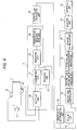
- FIG. 1 illustrates a gas shutoff apparatus according to the first embodiment of the present invention.
- a reference numeral 17 denotes a flow velocity detection unit, which transmits an ultrasound signal between an upstream vibrator 18 and a downstream vibrator 19, oppositely installed in a fluid path 1 of a gas medium such as a city gas or an LPG and detects a flow velocity of the use gas on the basis of its transfer time.
- the flow velocity detection unit 17 may be constructed as follows. Specifically, the flow velocity detection unit 17 comprises a switching return unit 20, a transmitting return unit 21, a receiving return unit 22, a repetition return unit 23, and a transfer time measurement return unit 24. The transmitting return unit 21 and the receiving return unit 22 are connected to the switching return unit 20.
- the switching return unit 20 alternately changes a connection destination between the transmitting return unit 21 and the receiving return unit 22, such that the transmitting return unit 21 and the receiving return unit 22 are connected to the upstream vibrator 18 and the downstream vibrator 19, respectively, and then, the transmitting return unit 21 and the receiving return unit 22 are connected to the downstream vibrator 19 and the upstream vibrator 18, respectively.
- the ultrasound signal transmitted from the transmitting return unit 21 passes from the upstream vibrator 18 through the fluid path, and then received from the downstream vibrator 19 to the receiving return unit 22 when the receiving return unit 22 is connected to the upstream vibrator 18 while the transmitting return unit 21 is connected to the downstream vibrator 19 using the switching return unit 20.
- the repetition return unit 23 repeatedly performs this transmission/receipt of the ultrasound signal, and repeatedly performs measurement of the signal transfer time using the transfer time measurement return unit 24 in the meanwhile.
- the transfer time measurement return unit 24 measures and accumulates the time taken from the transmission to the receipt of the ultrasound signal. Subsequently, the aforementioned operations are repeated by connecting the receiving return unit 22 and the transmitting return unit 21 to the downstream vibrator 19 and the upstream vibrator 18, respectively, using the switching return unit 20.
- the transfer time measurement return unit 24 obtains a transfer time difference between the transfer time obtained by initially receiving the ultrasound signal and the signal transfer time measured by switching the destination using the switching return unit 20.
- a reference numeral 25 denotes a flow volume calculation unit, which obtains an amount of the using medium, i.e., a gas flow volume, by converting the obtained transfer time.
- a reference numeral 26 denotes an abnormality determination unit, which determines whether or not there is an abnormal use condition on the basis of the gas use amount obtained using the flow volume calculation unit 25.
- the abnormal determination unit 26 stores a total flow volume shutoff value for detecting an abnormally large amount of flux generated when a hose supplying the gas to the use equipment such as a stove is removed due to some reasons or a use time shutoff table defining a limitation of the use time corresponding to the case where the equipment is used for a longer time than the maximum use time for which the equipment is typically used.
- a reference numeral 27 denotes a shutoff unit 27, which outputs a shutoff signal and shuts off a gas path 1 when the abnormality determination unit 26 determines that there is an abnormal condition.
- a reference numeral 28 denotes a return unit, which detects, using a switch or the like, a return instruction issued in order to open the fluid path that has been closed by the shutoff unit 27 due to the abnormal condition and make the gas medium available again and drives the shutoff unit 27 to open the fluid path.
- a reference numeral 29 denotes a return time-counting unit, which performs a time-counting after the operation of the return unit 28 and prohibits the flow volume obtained by detecting the flow velocity using the flow velocity detection unit 17 and calculating it using the flow volume calculation unit 25 in the meanwhile from being a target for determining leakage.
- a reference numeral 30 denotes a leakage determination unit, which determines whether or not the flow volume value obtained using the flow volume calculation unit 25 is zero or within a predetermined flow volume by detecting a flow velocity using the flow velocity detection unit 27 after the shutoff unit 27 becomes opened using the return unit 28, and then, the return time-counting unit 29 counts a predetermined time period, and outputs a shutoff signal to the shutoff unit 27 when it is determined that the flow volume value is not zero or within a predetermined flow volume.
- a reference numeral 31 denotes a notifying return unit, which displays contents or conditions of the shutoff operation as well as notifies a center of monitoring safety of the gas through a telephone line or the like when the abnormality determination unit 26 determines that there is an abnormal gas use condition and drives the shutoff unit 27.
- the use condition of the gas equipment is monitored using the fluid amount detected using the flow volume detection return unit 17.
- the supply of the gas is shutoff due to an abnormal use condition of the gas equipment when the gas equipment such as a gas stove or a boiler is abnormally used in houses of customer premises for a long time or when the gas hose is removed for some reasons and the gas abnormally leaks.
- the abnormality determination unit 26 determines whether or not the use gas amount is within a normal flow volume range by determining whether or not the transfer time detected using the flow velocity detection unit 17, i.e., the flow volume value converted from the flow velocity value using the flow volume calculation unit 25 is abnormally long, or is an abnormally larger flow volume value than a predefined value, Now, exemplary operations of the flow velocity detection unit 17 will be described.
- An ultrasound signal is transmitted and received between the upstream vibrator 18 and the downstream vibrator 19 obliquely installed in the fluid path 1 (i.e., a gas pipe).
- the transmitting return unit 21 is connected to the upstream vibrator 18, and the receiving return unit 22 is connected to the downstream vibrator 19 using the switching return unit 20 to receive the signal transmitted from the transmitting return unit 21 from the upstream vibrator 18 through the downstream vibrator 19.
- This operation is performed predetermined times set by the repetition return unit 23, to constitute, so called, a sing-around system.
- the transfer time measurement return unit 24 obtains the transfer time taken until the receiving return unit 22 receives the ultrasound signal transmitted from the transmitting return unit 21 by accumulating it.
- the transmitting return unit 21 is connected to the downstream vibrator 19, and the receiving return unit 22 is connected to the upstream vibrator 18.
- the ultrasound signal is output from the transmitting return unit 21, and received by the receiving return unit 22 connected to the upstream vibrator 18 through the downstream vibrator 19 and the fluid path 1. Similar to the above description, this operation is performed as much as times set by the repetition return unit 23.
- the transfer time measurement return unit 24 obtains the transfer time taken until the receiving return unit 22 receives the ultrasound signal transmitted from the transmitting return unit 21 by accumulating it, and obtains a transfer time difference between the transfer time taken when the ultrasound signal is transmitted from the upstream to the downstream and the transfer time transmitted from the downstream to the upstream.
- the flow volume calculation unit 25 converts the transfer time obtained by the transfer time measurement return unit 19, i.e., the flow velocity value V, into a flow volume value Q.
- a reference symbol A denotes a direction where the gas medium flows.
- the shutoff signal is output to the shutoff unit 27. Accordingly, the shutoff unit 27 is driven, and the fluid path 1 is closed to stop supply of the gas. In addition, when the shutoff signal is output, the content of the shutoff is displayed on the notifying return unit 31.
- the cause of the shutoff is removed, for example, when the hose erroneously installed is reinstalled, the return unit 28 is operated, and the shutoff unit 27 is driven, to open the fluid path, Then, it is identified whether or not a gas equipment user or a gas provider perfectly removes the cause of the shutoff by referencing the flow volume.
- the flow velocity value detected by the flow velocity detection unit 17 becomes zero or a value near zero.
- the return unit 28 is operated to open the shutoff unit 27 without removing the cause of the shutoff for some reasons, a large amount of flux flows, and then, the flow volume initially becomes a value near zero.
- the gas equipment plug located in the downstream of the pipe 1 is opened, the flow volume gradually increases and returns to the gas supply condition measured just before the shutoff although the gas is fully filled.
- the flow volume detected by the flow velocity detection unit 17 until a predetermined time period has been elapsed using the return time-counting unit 29 after the shutoff unit 27 is opened by the return unit 28 is not selected as a target of the leakage determination, but the leakage determination is performed using the flow volume measured after a predetermined time period has been elapsed.
- the leakage determination unit 29 determines whether or not the gas flow volume obtained by detecting the flow velocity using the flow velocity detection unit 17 after a predetermined time period has been elapsed using the return time-counting unit 29 and converting it into the flow volume using the flow volume calculation unit 25 is equal to or larger than a predetermined flow volume.
- the leakage determination unit 29 detects a predetermined flow volume or greater, it is determined that there is gas leakage, and the shutoff signal is output to the shutoff unit 27 again to stop supplying the gas.
- the shutoff signal is output to the shutoff unit 27 again to stop supplying the gas.
- the detected condition is normal, i.e., when the gas flow volume is not detected, it is determined that the cause of the shutoff is removed, and the fluid path 1 is opened, so that the gas equipment is recovered to a normal use condition.
- Fig. 2 illustrates a gas shutoff apparatus according to the second embodiment of the present invention.
- like reference numerals denotes like elements having the same functions as those of Figs. 1, 3, 4, and 9, and their descriptions are omitted.
- a reference numeral 32 denotes a return determination unit.
- the return unit 28 is operated, and the return time-counting unit 29 counts that a predetermined time period has been elapsed. In the meanwhile, a large amount of flux flows until the gas pressure in the pipe reaches the same pressure as that of the upstream of the shutoff unit 27. Since a pipe length between the gas shutoff apparatus and the gas equipment is different for each customer premise, the time for filling the pipe to the same pressure is also different. However, this time is previously studied in each installation, and set in the return time-counting unit 29.
- the use condition of the gas equipment is monitored using a flow volume detected by the flow velocity detection unit 27.
- the supply of the gas is shutoff due to an abnormal use condition of the gas equipment when the gas equipment such as a gas stove or a boiler is abnormally used in houses of customer premises for a long time or when the gas hose is removed for some reasons and the gas abnormally leaks.
- the abnormality determination unit 26 determines whether or not the use gas amount is within a normal flow volume range by determining whether or not the transfer time detected using the flow velocity detection unit 17, i.e., the flow volume value converted from the flow velocity value using the flow volume calculation unit 25 is abnormally long, or is an abnormally larger flow volume value than a predefined value. Now, exemplary operations of the flow velocity detection unit 17 will be described.
- An ultrasound signal is transmitted and received between the upstream vibrator 18 and the downstream vibrator 19 obliquely installed in the fluid path 1 (i.e., a gas pipe),
- the transmitting return unit 21 is connected to the upstream vibrator 18, and the receiving return unit 22 is connected to the downstream vibrator 19 using the switching return unit 20 to receive the signal transmitted from the transmitting return unit 21 from the upstream vibrator 18 through the downstream vibrator 19.
- This operation is performed predetermined times set by the repetition return unit 23, to constitute, so called, a sing-around system.
- the transfer time measurement return unit 24 obtains the transfer time taken until the receiving return unit 22 receives the ultrasound signal transmitted from the transmitting return unit 21 by accumulating it.
- the transmitting return unit 21 is connected to the downstream vibrator 19, and the receiving return unit 22 is connected to the upstream vibrator 18.
- the ultrasound signal is output from the transmitting return unit 21, and received by the receiving return unit 22 connected to the upstream vibrator 18 through the downstream vibrator 19 and the fluid path 1. Similar to the above description, this operation is performed as much as times set by the repetition return unit 23.
- the transfer time measurement return unit 24 obtains the transfer time taken until the receiving return unit 22 receives the ultrasound signal transmitted from the transmitting return unit 21 by accumulating it, and obtains a transfer time difference between the transfer time taken when the ultrasound signal is transmitted from the upstream to the downstream and the transfer time transmitted from the downstream to the upstream.
- the flow volume calculation unit 25 converts the transfer time obtained by the transfer time measurement return unit 19, i.e., the flow velocity value V, into a flow volume value Q.
- a reference symbol A denotes a direction where the gas medium flows.
- the shutoff signal is output to the shutoff unit 27. Accordingly, the shutoff unit 27 is driven, and the fluid path 1 is closed to stop supply of the gas. In addition, when the shutoff signal is output, the content of the shutoff is displayed on the notifying return unit 31.
- the cause of the shutoff is removed, for example, when the hose erroneously installed is reinstalled, the return unit 28 is operated, and the shutoff unit 27 is driven, to open the fluid path. Then, it is identified whether or not a gas equipment user or a gas provider perfectly removes the cause of the shutoff by referencing the flow volume.
- the flow velocity value detected by the flow velocity detection unit 17 becomes zero or a value near zero.
- the return unit 28 is operated to open the shutoff unit 27 without removing the cause of the shutoff for some reasons, a large amount of flux flows, and then, the flow volume initially becomes a value near zero.
- the gas equipment plug located in the downstream of the pipe 1 is opened, the flow volume gradually increases and returns to the gas supply condition measured just before the shutoff although the gas is fully filled.
- the flow volume detected by the flow velocity detection unit 17 until a predetermined time period has been elapsed using the return time-counting unit 29 after the shutoff unit 27 is opened by the return unit 28 is not selected as a target of the leakage determination, but the leakage determination is performed using the flow volume measured after a predetermined time period has been elapsed. In this case, since a pipe length between the gas shutoff apparatus and the gas equipment in each customer premise is different.
- the return determination unit 32 determines the time for flowing a larger flow volume in each customer premise and stabilizing the fluid by previously studying it, and set the studied value to a determination value of the return time-counting unit 29.
- the leakage determination unit 29 determines whether or not the gas flow volume obtained by detecting the flow velocity using the flow velocity detection unit 17 after a predetermined time period has been elapsed using the return time-counting unit 29 and converting it into the flow volume using the flow volume calculation unit 25 is equal to or larger than a predetermined flow volume.
- the leakage determination unit 29 detects a predetermined flow volume or greater, it is determined that there is gas leakage, and the shutoff signal is output to the shutoff unit 27 again to stop supplying the gas.
- Fig. 3 illustrates a gas shutoff apparatus according to the third embodiment of the present invention.
- like reference numerals denotes like elements having the same functions as those of Figs. 1, 2, 4, and 9, and their descriptions are omitted.
- a reference numeral 33 denotes a return flow volume determination unit.
- the return unit 28 is operated, and the return time-counting unit 29 counts that a predetermined time period has been elapsed.
- a large amount of flux flows until the gas pressure in the pipe reaches the same pressure as that of the upstream of the shutoff unit 27. Since a pipe length between the gas shutoff apparatus and the gas equipment is different for each customer premise, the flow volume is reduced to a value near zero once the pipe is filled with the gas until the same pressure. However, when the cause of the shutoff is not removed for some reasons, and the equipment plug is recovered to an open state, the flow volume does not become zero, and a minute flow volume continues to flow. It is determined whether or not this minute flow volume is equal to or larger than a predetermined flow volume value.
- the use condition of the gas equipment is monitored using a flow volume detected by the flow velocity detection unit 27.
- the supply of the gas is shutoff due to an abnormal use condition of the gas equipment when the gas equipment such as a gas stove or a boiler is abnormally used in houses of customer premises for a long time or when the gas hose is removed for some reasons and the gas abnormally leaks.
- the abnormality determination unit 26 determines whether or not the use gas amount is within a normal flow volume range by determining whether or not the transfer time detected using the flow velocity detection unit 17, i.e., the flow volume value converted from the flow velocity value using the flow volume calculation unit 25, is abnormally long, or is an abnormally larger flow volume value than a predefined value. Now, exemplary operations of the flow velocity detection unit 17 will be described.
- An ultrasound signal is transmitted and received between the upstream vibrator 18 and the downstream vibrator 19 obliquely installed in the fluid path 1 (i.e., a gas pipe).
- the transmitting return unit 21 is connected to the upstream vibrator 18, and the receiving return unit 22 is connected to the downstream vibrator 19 using the switching return unit 20 to receive the signal transmitted from the transmitting return unit 21 from the upstream vibrator 18 through the downstream vibrator 19.
- This operation is performed predetermined times set by the repetition return unit 23, to constitute, so called, a sing-around system.
- the transfer time measurement return unit 24 obtains the transfer time taken until the receiving return unit 22 receives the ultrasound signal transmitted from the transmitting return unit 21 by accumulating it.
- the transmitting return unit 21 is connected to the downstream vibrator 19, and the receiving return unit 22 is connected to the upstream vibrator 18.
- the ultrasound signal is output from the transmitting return unit 21, and received by the receiving return unit 22 connected to the upstream vibrator 18 through the downstream vibrator 19 and the fluid path 1. Similar to the above description, this operation is performed as much as times set by the repetition return unit 23.
- the transfer time measurement return unit 24 obtains the transfer time taken until the receiving return unit 22 receives the ultrasound signal transmitted from the transmitting return unit 21 by accumulating it, and obtains a transfer time difference between the transfer time taken when the ultrasound signal is transmitted from the upstream to the downstream and the transfer time transmitted from the downstream to the upstream.
- the flow volume calculation unit 25 converts the transfer time obtained by the transfer time measurement return unit 19, i.e., the flow velocity value V, into a flow volume value Q.
- a reference symbol A denotes a direction where the gas medium flows.
- the shutoff signal is output to the shutoff unit 27. Accordingly, the shutoff unit 27 is driven, and the fluid path 1 is closed to stop supplying the gas. In addition, when the shutoff signal is output, the content of the shutoff is displayed on the notifying return unit 31.
- the cause of the shutoff is removed, for example, when the hose erroneously installed is reinstalled, the return unit 28 is operated, and the shutoff unit 27 is driven, to open the fluid path. Then, it is identified whether or not a gas equipment user or a gas provider perfectly removes the cause of the shutoff by referencing the flow volume.
- the flow velocity value detected by the flow velocity detection unit 17 becomes zero or a value near zero.
- the return unit 28 is operated to open the shutoff unit 27 without removing the cause of the shutoff for some reasons, a large amount of flux flows, and then, the flow volume initially becomes a value near zero.
- the gas equipment plug located in the downstream of the pipe 1 is opened, the flow volume gradually increases and returns to the gas supply condition measured just before the shutoff although the gas is fully filled.
- the flow volume detected by the flow velocity detection unit 17 until a predetermined time period has been elapsed using the return time-counting unit 29 after the shutoff unit 27 is opened by the return unit 28 is not selected as a target of the leakage determination, but the leakage determination is performed using the flow volume measured after a predetermined time period has been elapsed.
- a pipe length between the gas shutoff apparatus and the gas equipment in each customer premise is different.
- the return flow volume determination unit 33 determines whether or not the minute flow volume stabilized after a larger flow volume flows is equal to or larger than a predetermined value for each customer premise. When the minute flow volume is equal to or larger than the predetermined value, it is determined that there is possibility of leakage, and the return flow volume determination unit 33 does not determine that the return operation in which the gas is available is not completed, but continues to leakage determination.
- the leakage determination unit 29 determines whether or not the gas flow volume obtained by detecting the flow velocity using the flow velocity detection unit 17 and converting it into the flow volume using the flow volume calculation unit 25 increases to a predetermined flow volume.
- the leakage determination unit 29 detects a predetermined flow volume or greater, it is determined that there is gas leakage, and the shutoff signal is output to the shutoff unit 27 again to stop supplying the gas.
- the shutoff signal is output to the shutoff unit 27 again to stop supplying the gas.
- the detected condition is normal, i.e., when the gas flow volume is not detected, it is determined that the cause of the shutoff is removed, and the fluid path 1 is opened, so that the gas equipment is recovered to a normal use condition.
- Fig. 4 illustrates a gas shutoff apparatus according to the fourth embodiment of the present invention.
- like reference numerals denotes like elements having the same functions as those of Figs. 1, 2, 3, and 9, and their descriptions are omitted.
- a reference numeral 34 denotes a flow volume variation determination unit.
- the return unit 28 is operated, and the return time-counting unit 29 counts that a predetermined time period has been elapsed. In the meanwhile, a large amount of flux flows until the gas pressure in the pipe reaches the same pressure as that of the upstream of the shutoff unit 27. Since a pipe length between the gas shutoff apparatus and the gas equipment is different for each customer premise, the flow volume is reduced to a value near zero once the pipe is filled with the gas until the same pressure. However, when the cause of the shutoff is not removed for some reasons, and the equipment plug is recovered to an open state, the flow volume does not become zero, and a minute flow volume continues to flow. Then, the flow volume gradually increases.
- the flow volume variation determination unit 34 determines whether or not this flow volume variation gradient is equal to or larger than a predetermined value.
- a reference numeral 35 denotes a leakage estimation unit, which determines, when the flow volume variation determination unit 34 detects a flow volume variation gradient, whether or not a leakage flow volume after a predetermined time period corresponding to the variation gradient has reached a predetermined value.
- the use condition of the gas equipment is monitored using a flow volume detected by the flow velocity detection unit 27.
- the supply of the gas is shutoff due to an abnormal use condition of the gas equipment when the gas equipment such as a gas stove or a boiler is abnormally used in houses of customer premises for a long time or when the gas hose is removed for some reasons and the gas abnormally leaks.
- the abnormality determination unit 26 determines whether or not the use gas amount is within a normal flow volume range by determining whether or not the transfer time detected using the flow velocity detection unit 17, i.e., the flow volume value converted from the flow velocity value using the flow volume calculation unit 25, is abnormally long, or is an abnormally larger flow volume value than a predefined value. Now, exemplary operations of the flow velocity detection unit 17 will be described.
- An ultrasound signal is transmitted and received between the upstream vibrator 18 and the downstream vibrator 19 obliquely installed in the fluid path 1 (i.e., a gas pipe).
- the transmitting return unit 21 is connected to the upstream vibrator 18, and the receiving return unit 22 is connected to the downstream vibrator 19 using the switching return unit 20 to receive the signal transmitted from the transmitting return unit 21 from the upstream vibrator 18 through the downstream vibrator 19.
- This operation is performed predetermined times set by the repetition return unit 23, to constitute, so called, a sing-around system.
- the transfer time measurement return unit 24 obtains the transfer time taken until the receiving return unit 22 receives the ultrasound signal transmitted from the transmitting return unit 21 by accumulating it.
- the transmitting return unit 21 is connected to the downstream vibrator 19, and the receiving return unit 22 is connected to the upstream vibrator 18.
- the ultrasound signal is output from the transmitting return unit 21, and received by the receiving return unit 22 connected to the upstream vibrator 18 through the downstream vibrator 19 and the fluid path 1. Similar to the above description, this operation is performed as much as times set by the repetition return unit 23.
- the transfer time measurement return unit 24 obtains the transfer time taken until the receiving return unit 22 receives the ultrasound signal transmitted from the transmitting return unit 21 by accumulating it, and obtains a transfer time difference between the transfer time taken when the ultrasound signal is transmitted from the upstream to the downstream and the transfer time transmitted from the downstream to the upstream.
- the flow volume calculation unit 25 converts the transfer time obtained by the transfer time measurement return unit 19, i.e., the flow velocity value V, into a flow volume value Q.
- a reference symbol A denotes a direction where the gas medium flows.
- the shutoff signal is output to the shutoff unit 27. Accordingly, the shutoff unit 27 is driven, and the fluid path 1 is closed to stop supplying the gas. In addition, when the shutoff signal is output, the content of the shutoff is displayed on the notifying return unit 31.
- the cause of the shutoff is removed, for example, when the hose erroneously installed is reinstalled, the return unit 28 is operated, and the shutoff unit 27 is driven, to open the fluid path, Then, it is identified whether or not a gas equipment user or a gas provider perfectly removes the cause of the shutoff by referencing the flow volume.
- the flow velocity value detected by the flow velocity detection unit 17 becomes zero or a value near zero.
- the return unit 28 is operated to open the shutoff unit 27 without removing the cause of the shutoff for some reasons, a large amount of flux flows, and then, the flow volume initially becomes a value near zero.
- this minute flow volume is different depending on the pipe length, it takes a long time to the pipe when the pipe length is long. Since the gas equipment plug located in the downstream of the pipe 1 is opened, when the gas is fully filled, the pressure difference from a second side of the equipment plug increases, and the flow volume gradually starts to increase and returns to the gas supply condition measured just before the shutoff.
- the flow volume detected by the flow velocity detection unit 17 until a predetermined time period has been elapsed using the return time-counting unit 29 after the shutoff unit 27 is opened by the return unit 28 is not selected as a target of the leakage determination, but the leakage determination is performed using the flow volume measured after a predetermined time period has been elapsed.
- a pipe length between the gas shutoff apparatus and the gas equipment in each customer premise is different.
- the return flow volume determination unit 33 determines whether or not the minute flow volume stabilized after a larger flow volume flows is equal to or larger than a predetermined value for each customer premise. When the minute flow volume is equal to or larger than the predetermined value, it is determined that there is possibility of leakage, and the return flow volume determination unit 33 does not determine that the return operation in which the gas is available is not completed, but continues to leakage determination.
- the leakage determination unit 29 determines, on the basis of the flow volume variation gradient, whether or not the gas flow volume obtained by detecting the flow velocity using the flow velocity detection unit 17 and converting it into the flow volume using the flow volume calculation unit 25 increases to a predetermined flow volume.
- the leakage determination unit 29 determines whether or not the flow volume variation gradient detected using the flow volume variation determination unit 34 has reached a leakage flow volume value within a predetermined time period.
- the flow volume does not become zero, but a minute flow volume near zero continues to flow.
- the minute flow volume continues to stably flow for a predetermined time period, the flow volume starts to increase, and finally, an original flow volume measured when the equipment plug is opened flows.
- the leakage estimation unit 35 determines that the flow volume increases to a predetermined flow volume value or greater than the flow volume variation gradient, it is determined that there is gas leakage, and the shutoff signal is output to the shutoff unit 27 again to stop supplying the gas.
- FIG. 5 illustrates a gas shutoff apparatus according to the fifth embodiment of the present invention.
- a reference numeral 17 denotes a flow velocity detection unit, which transmits an ultrasound signal between an upstream vibrator 18 and a downstream vibrator 19, oppositely installed in a fluid path 1 of a gas medium such as a city gas or an LPG and detects a flow velocity of the use gas on the basis of its transfer time.
- the flow velocity detection unit 17 may be constructed as follows. Specifically, the flow velocity detection unit 17 comprises a switching return unit 20, a transmitting return unit 21, a receiving return unit 22, a repetition return unit 23, and a transfer time measurement return unit 24. The transmitting return unit 21 and the receiving return unit 22 are connected to the switching return unit 20.
- the switching return unit 20 alternately changes a connection destination between the transmitting return unit 21 and the receiving return unit 22, such that the transmitting return unit 21 and the receiving return unit 22 are connected to the upstream vibrator 18 and the downstream vibrator 19, respectively, and then, the transmitting return unit 21 and the receiving return unit 22 are connected to the downstream vibrator 19 and the upstream vibrator 18, respectively.
- the ultrasound signal transmitted from the transmitting return unit 21 passes from the upstream vibrator 18 through the fluid path, and then received from the downstream vibrator 19 to the receiving return unit 22 when the receiving return unit 22 is connected to the upstream vibrator 18 while the transmitting return unit 21 is connected to the downstream vibrator 19 using the switching return unit 20.
- the repetition return unit 23 repeatedly performs this transmission/receipt of the ultrasound signal, and repeatedly performs measurement of the signal transfer time using the transfer time measurement return unit 24 in the meanwhile.
- the transfer time measurement return unit 24 measures and accumulates the time taken from the transmission to the receipt of the ultrasound signal. Subsequently, the aforementioned operations are repeated by connecting the receiving return unit 22 and the transmitting return unit 21 to the downstream vibrator 19 and the upstream vibrator 18, respectively, using the switching return unit 20.
- the transfer time measurement return unit 24 obtains a transfer time difference between the transfer time obtained by initially receiving the ultrasound signal and the signal transfer time measured by switching the destination using the switching return unit 20.
- a reference numeral 25 denotes a flow volume calculation unit, which obtains an amount of the using medium, i.e., a gas flow volume, by converting the obtained transfer time.
- a reference numeral 26 denotes an abnormality determination unit, which determines whether or not there is an abnormal use condition on the basis of the gas use amount obtained using the flow volume calculation unit 25.
- the abnormal determination unit 26 stores a total flow volume shutoff value for detecting an abnormally large amount of flux generated when a hose supplying the gas to the use equipment such as a stove is removed due to some reasons or a use time shutoff table defining a limitation of the use time corresponding to the case where the equipment is used for a longer time than the maximum use time for which the equipment is typically used.
- a reference numeral 27 denotes a shutoff unit 27, which outputs a shutoff signal and shuts off a gas path 1 when the abnormality determination unit 26 determines that there is an abnormal condition.
- a reference numeral 28 denotes a return unit, which detects, using a switch or the like, a return instruction issued in order to open the fluid path that has been closed by the shutoff unit 27 due to the abnormal condition and make the gas medium available again and drives the shutoff unit 27 to open the fluid path.
- a reference numeral 29 denotes a return time-counting unit, which performs a time-counting after the operation of the return unit 28 and prohibits the flow volume detected using the flow velocity detection unit 17 and obtained using the flow volume calculation unit 25 in the meanwhile from being a target for determining leakage.
- a reference numeral 130 denotes a pressure detection unit, which detects the pressure in the pipe.
- a reference numeral 131 denotes a pressure setting return unit, which sets a pressure in the pipe for stopping use of the equipment, i.e., a blockage pressure.
- a reference numeral 132 denotes a pressure determination unit, which compares the pressure detected using the pressure detection unit 130 after the return with the pressure in the pressure setting return unit 131, and determines whether or not the pressure measured after the return operation is performed and then, the time of the return time-counting unit has been elapsed is equal to or larger than the blockage pressure.
- a reference numeral 133 denotes a leakage determination unit, which determines whether or not the pressure obtained by opening the shutoff unit 27 using the return unit 28, detecting a pressure using the pressure detection unit 130 after a predetermined time period has been elapsed by the return time-counting unit 29, and determining the pressure using the pressure determination unit 32 is equal to or larger than the blockage pressure, and determines that there is leakage if the pressure is not equal to or larger than the blockage pressure to output the shutoff signal to the shutoff unit 27.
- a reference numeral 134 denotes a notifying return unit, which displays contents or conditions of the shutoff operation as well as notifies a center of monitoring safety of the gas through a telephone line or the like when the abnormality determination unit 26 determines that there is an abnormal gas use condition and drives the shutoff unit 27.
- the use condition of the gas equipment is monitored using the fluid amount detected using the flow volume detection return unit 17.
- the supply of the gas is shutoff due to an abnormal use condition of the gas equipment when the gas equipment such as a gas stove or a boiler is abnormally used in houses of customer premises for a long time or when the gas hose is removed for some reasons and the gas abnormally leaks.
- the abnormality determination unit 26 determines whether or not the use gas amount is within a normal flow volume range by determining whether or not the transfer time detected using the flow velocity detection unit 17, i.e., the flow volume value converted from the flow velocity value using the flow volume calculation unit 25 is abnormally long, or is an abnormally larger flow volume value than a predefined value. Now, exemplary operations of the flow velocity detection unit 17 will be described.
- An ultrasound signal is transmitted and received between the upstream vibrator 18 and the downstream vibrator 19 obliquely installed in the fluid path 1 (i.e., a gas pipe).
- the transmitting return unit 21 is connected to the upstream vibrator 18, and the receiving return unit 22 is connected to the downstream vibrator 19 using the switching return unit 20 to receive the signal transmitted from the transmitting return unit 21 from the upstream vibrator 18 through the downstream vibrator 19.
- This operation is performed predetermined times set by the repetition return unit 23, to constitute, so called, a sing-around system.
- the transfer time measurement return unit 24 obtains the transfer time taken until the receiving return unit 22 receives the ultrasound signal transmitted from the transmitting return unit 21 by accumulating it.
- the transmitting return unit 21 is connected to the downstream vibrator 19, and the receiving return unit 22 is connected to the upstream vibrator 18.
- the ultrasound signal is output from the transmitting return unit 21, and received by the receiving return unit 22 connected to the upstream vibrator 18 through the downstream vibrator 19 and the fluid path 1. Similar to the above description, this operation is performed as much as times set by the repetition return unit 23.
- the transfer time measurement return unit 24 obtains the transfer time taken until the receiving return unit 22 receives the ultrasound signal transmitted from the transmitting return unit 21 by accumulating it, and obtains a transfer time difference between the transfer time taken when the ultrasound signal is transmitted from the upstream to the downstream and the transfer time transmitted from the downstream to the upstream.
- the flow volume calculation unit 25 converts the transfer time obtained by the transfer time measurement return unit 19, i.e., the flow velocity value V, into a flow volume value Q.
- a reference symbol A denotes a direction where the gas medium flows.
- the shutoff signal is output to the shutoff unit 27. Accordingly, the shutoff unit 27 is driven, and the fluid path 1 is closed to stop supplying the gas. In addition, when the shutoff signal is output, the content of the shutoff is displayed on the notifying return unit 134.
- the cause of the shutoff is removed, for example, when the hose erroneously installed is reinstalled, the return unit 28 is operated, and the shutoff unit 27 is driven, to open the fluid path. Then, it is identified whether or not a gas equipment user or a gas provider perfectly removes the cause of the shutoff by referencing the flow volume.
- the flow volume gradually increases and returns to a pressure, (i.e., a control pressure) measured during use of the equipment just before the shutoff although the gas is fully filled.
- a pressure i.e., a control pressure
- the flow volume or the pressure detected by the flow velocity detection unit 17 or the pressure detection unit 130 until a predetermined time period has been elapsed using the return time-counting unit 29 after the shutoff unit 27 is opened by the return unit 28 is not selected as a target of the leakage determination, but the leakage determination is performed using the flow volume measured after a predetermined time period has been elapsed.
- the leakage determination unit 133 determines a determination signal on whether or not there is a predetermined pressure by detecting a pressure after a predetermined time period has been elapsed by the return time-counting unit 29 using the pressure detection unit 17 and comparing the detected pressure with the setup pressure of the pressure setting return unit 131 using the pressure determination unit 132.
- the pressure setting return unit 131 has a blockage pressure for stopping the equipment.
- the leakage determination unit 33 determines that there is gas leakage when the pressure which is equal to or lower than the blockage pressure is detected, and output the shutoff signal to the shutoff unit 27 to stop supplying the gas.
- Fig. 6 illustrates a gas shutoff apparatus according to the sixth embodiment of the present invention.
- like reference numerals denotes like elements having the same functions as those of Figs. 5, 7, 8, and 9, and their descriptions are omitted.
- a reference numeral 35 denotes a pressure storing unit, which detects a pressure (i.e., a control pressure) detected by the pressure detection unit 130 during the equipment is in use (i.e., when the flow volume detected by the flow velocity detection unit 17 is not near zero, an equipment flow volume is detected) and stores its maximum value. Although not shown in the drawing, the maximum value is periodically cleared, detected and then, stored again.
- a pressure i.e., a control pressure
- the use condition of the gas equipment is monitored using the flow volume detected by the flow velocity detection unit 27.
- the supply of the gas is shutoff due to an abnormal use condition of the gas equipment when the gas equipment such as a gas stove or a boiler is abnormally used in houses of customer premises for a long time or when the gas hose is removed for some reasons and the gas abnormally leaks.
- the abnormality determination unit 26 determines whether or not the use gas amount is within a normal flow volume range by determining whether or not the transfer time detected using the flow velocity detection unit 17, i.e., the flow volume value converted from the flow velocity value using the flow volume calculation unit 25 is abnormally long, or is an abnormally larger flow volume value than a predefined value. Now, exemplary operations of the flow velocity detection unit 17 will be described.
- An ultrasound signal is transmitted and received between the upstream vibrator 18 and the downstream vibrator 19 obliquely installed in the fluid path 1 (i.e., a gas pipe).
- the transmitting return unit 21 is connected to the upstream vibrator 18, and the receiving return unit 22 is connected to the downstream vibrator 19 using the switching return unit 20 to receive the signal transmitted from the transmitting return unit 21 from the upstream vibrator 18 through the downstream vibrator 19.
- This operation is performed predetermined times set by the repetition return unit 23, to constitute, so called, a sing-around system.
- the transfer time measurement return unit 24 obtains the transfer time taken until the receiving return unit 22 receives the ultrasound signal transmitted from the transmitting return unit 21 by accumulating it.
- the transmitting return unit 21 is connected to the downstream vibrator 19, and the receiving return unit 22 is connected to the upstream vibrator 18.
- the ultrasound signal is output from the transmitting return unit 21, and received by the receiving return unit 22 connected to the upstream vibrator 18 through the downstream vibrator 19 and the fluid path 1. Similar to the above description, this operation is performed as much as times set by the repetition return unit 23.
- the transfer time measurement return unit 24 obtains the transfer time taken until the receiving return unit 22 receives the ultrasound signal transmitted from the transmitting return unit 21 by accumulating it, and obtains a transfer time difference between the transfer time taken when the ultrasound signal is transmitted from the upstream to the downstream and the transfer time transmitted from the downstream to the upstream.
- the flow volume calculation unit 25 converts the transfer time obtained by the transfer time measurement return unit 19, i.e., the flow velocity value V, into a flow volume value Q.
- a reference symbol A denotes a direction where the gas medium flows.
- the pressure detection unit 130 detects a supply pressure (i.e., a control pressure) and store its maximum value in the pressure storing unit 135.
- the pressure storing unit 135 stores a history of the maximum supply pressures.
- the shutoff signal is output to the shutoff unit 27. Accordingly, the shutoff unit 27 is driven, and the fluid path 1 is closed to stop supplying the gas. In addition, when the shutoff signal is output, the content of the shutoff is displayed on the notifying return unit 134.
- the cause of the shutoff is removed, for example, when the hose erroneously installed is reinstalled, the return unit 28 is operated, and the shutoff unit 27 is driven, to open the fluid path. Then, it is identified whether or not a gas equipment user or a gas provider perfectly removes the cause of the shutoff by referencing the flow volume.
- the flow velocity value detected by the flow velocity detection unit 17 becomes nearly a blockage pressure, i.e., a pressure value measured when the equipment stops.
- a blockage pressure i.e., a pressure value measured when the equipment stops.
- the return unit 28 is operated to open the shutoff unit 27 without removing the cause of the shutoff for some reasons, a large amount of flux flows, and the gas pressure in the pipe increases to nearly a blockage pressure.
- the gas equipment plug located in the downstream of the pipe 1 is opened, the flow volume gradually increases and returns to the gas supply condition (i.e., a control pressure) measured during the equipment is in use just before the shutoff although the gas is fully filled.
- the flow volume or the pressure detected by the flow velocity detection unit 17 until a predetermined time period has been elapsed using the return time-counting unit 29 after the shutoff unit 27 is opened by the return unit 28 is not selected as a target of the leakage determination, but the leakage determination is performed using the flow volume measured after a predetermined time period has been elapsed.
- the pressure determination unit 132 compares the pressure detected using the pressure detection unit 17 after a predetermined time period has been elapsed by the return time-counting unit 29 with the maximum value of the control pressure stored in the pressure storing unit 135.
- the leakage determination unit 133 determines a determination signal on whether or not a pressure detected using a value obtained by adding a predetermined pressure to the maximum control pressure is high.
- the leakage determination unit 133 determines that there is gas leakage when the pressure is equal to or lower than the stored maximum control pressure, and outputs the shutoff signal to the shutoff unit 27 to stop supplying the gas.
- Fig. 7 illustrates a gas shutoff apparatus according to the seventh embodiment of the present invention.
- like reference numerals denotes like elements having the same functions as those of Figs. 5, 6, 8, and 9, and their descriptions are omitted.
- a reference numeral 136 denotes a pressure variation determination unit, which obtains a pressure variation gradient on the basis of the pressure detected by the pressure detection unit 130, and determines whether or not the pressure is reduced from the blockage pressure to the control pressure.
- a reference numeral 137 denotes a leakage estimation unit, which detects a negative pressure variation gradient using the pressure variation determination unit 136, and estimates whether or not the pressure corresponding to the variation gradient is below the blockage pressure that has been set by the pressure setting return unit 131. The shutoff signal is output when it is estimated that the pressure corresponding to the variation gradient is reduced below the blockage pressure.
- the use condition of the gas equipment is monitored using the flow volume detected by the flow velocity detection unit 27.
- the supply of the gas is shutoff due to an abnormal use condition of the gas equipment when the gas equipment such as a gas stove or a boiler is abnormally used in houses of customer premises for a long time or when the gas hose is removed for some reasons and the gas abnormally leaks.
- the abnormality determination unit 26 determines whether or not the use gas amount is within a normal flow volume range by determining whether or not the transfer time detected using the flow velocity detection unit 17, i.e., the flow volume value converted from the flow velocity value using the flow volume calculation unit 25 is abnormally long, or is an abnormally larger flow volume value than a predefined value. Now, exemplary operations of the flow velocity detection unit 17 will be described.
- An ultrasound signal is transmitted and received between the upstream vibrator 18 and the downstream vibrator 19 obliquely installed in the fluid path 1 (i.e., a gas pipe).
- the transmitting return unit 21 is connected to the upstream vibrator 18, and the receiving return unit 22 is connected to the downstream vibrator 19 using the switching return unit 20 to receive the signal transmitted from the transmitting return unit 21 from the upstream vibrator 18 through the downstream vibrator 19.
- This operation is performed predetermined times set by the repetition return unit 23, to constitute, so called, a sing-around system.
- the transfer time measurement return unit 24 obtains the transfer time taken until the receiving return unit 22 receives the ultrasound signal transmitted from the transmitting return unit 21 by accumulating it.
- the transmitting return unit 21 is connected to the downstream vibrator 19, and the receiving return unit 22 is connected to the upstream vibrator 18.
- the ultrasound signal is output from the transmitting return unit 21, and received by the receiving return unit 22 connected to the upstream vibrator 18 through the downstream vibrator 19 and the fluid path 1. Similar to the above description, this operation is performed as much as times set by the repetition return unit 23.
- the transfer time measurement return unit 24 obtains the transfer time taken until the receiving return unit 22 receives the ultrasound signal transmitted from the transmitting return unit 21 by accumulating it, and obtains a transfer time difference between the transfer time taken when the ultrasound signal is transmitted from the upstream to the downstream and the transfer time transmitted from the downstream to the upstream.
- the flow volume calculation unit 25 converts the transfer time obtained by the transfer time measurement return unit 19, i.e., the flow velocity value V, into a flow volume value Q.
- a reference symbol A denotes a direction where the gas medium flows.
- the shutoff signal is output to the shutoff unit 27. Accordingly, the shutoff unit 27 is driven, and the fluid path 1 is closed to stop supplying the gas. In addition, when the shutoff signal is output, the content of the shutoff is displayed on the notifying return unit 134.
- the cause of the shutoff is removed, for example, when the hose erroneously installed is reinstalled, the return unit 28 is operated, and the shutoff unit 27 is driven, to open the fluid path. Then, it is identified whether or not a gas equipment user or a gas provider perfectly removes the cause of the shutoff by referencing the flow volume.
- the flow velocity value detected by the flow velocity detection unit 17 becomes nearly a blockage pressure, i.e., a pressure value measured when the equipment stops.
- a blockage pressure i.e., a pressure value measured when the equipment stops.
- the return unit 28 is directly operated to open the shutoff unit 27 without removing the cause of the shutoff for some reasons, a large amount of flux flows, and the gas pressure in the pipe increases to nearly a blockage pressure.
- the gas equipment plug located in the downstream of the pipe 1 is opened, the flow volume gradually increases and returns to the gas supply condition (i.e., a control pressure) measured during the equipment is used just before the shutoff although the gas is fully filled.
- the flow volume or the pressure detected by the flow velocity detection unit 17 until a predetermined time period has been elapsed using the return time-counting unit 29 after the shutoff unit 27 is opened by the return unit 28 is not selected as a target of the leakage determination, but the leakage determination is performed using the flow volume measured after a predetermined time period has been elapsed.
- the pressure detection unit 17 detects a pressure changed after a predetermined time period has been elapsed by the return time-counting unit 29, and the pressure variation determination unit 136 obtains a pressure variation gradient. If there is leakage, the pressure value has a tendency to be reduced from the blockage pressure to the control pressure.
- the pressure setting return unit 131 sets the blockage pressure of a time point when the equipment stops.
- the leakage determination unit 133 estimates the reduction value of the pressure. If it is estimated that the pressure is reduced to the blockage pressure or lower after a predetermined time period has been elapsed, it is determined that there is gas leakage, and the shutoff signal is output to the shutoff unit 27 again to stop supplying the gas.
- Fig. 8 illustrates a gas shutoff apparatus according to the seventh embodiment of the present invention.
- like reference numerals denotes like elements having the same functions as those of Figs. 5, 6, 7, and 9, and their descriptions are omitted.
- a reference numeral 138 denotes a leakage determination unit.
- the use condition of the gas equipment is monitored using the flow volume detected by the flow velocity detection unit 27.
- the supply of the gas is shutoff due to an abnormal use condition of the gas equipment when the gas equipment such as a gas stove or a boiler is abnormally used in houses of customer premises for a long time or when the gas hose is removed for some reasons and the gas abnormally leaks.
- the abnormality determination unit 26 determines whether or not the use gas amount is within a normal flow volume range by determining whether or not the transfer time detected using the flow velocity detection unit 17, i.e., the flow volume value converted from the flow velocity value using the flow volume calculation unit 25 is abnormally long, or is an abnormally larger flow volume value than a predefined value. Now, exemplary operations of the flow velocity detection unit 17 will be described.
- An ultrasound signal is transmitted and received between the upstream vibrator 18 and the downstream vibrator 19 obliquely installed in the fluid path 1 (i.e., a gas pipe).
- the transmitting return unit 21 is connected to the upstream vibrator 18, and the receiving return unit 22 is connected to the downstream vibrator 19 using the switching return unit 20 to receive the signal transmitted from the transmitting return unit 21 from the upstream vibrator 18 through the downstream vibrator 19.
- This operation is performed predetermined times set by the repetition return unit 23, to constitute, so called, a sing-around system.
- the transfer time measurement return unit 24 obtains the transfer time taken until the receiving return unit 22 receives the ultrasound signal transmitted from the transmitting return unit 21 by accumulating it.
- the transmitting return unit 21 is connected to the downstream vibrator 19, and the receiving return unit 22 is connected to the upstream vibrator 18.
- the ultrasound signal is output from the transmitting return unit 21, and received by the receiving return unit 22 connected to the upstream vibrator 18 through the downstream vibrator 19 and the fluid path 1. Similar to the above description, this operation is performed as much as times set by the repetition return unit 23.
- the transfer time measurement return unit 24 obtains the transfer time taken until the receiving return unit 22 receives the ultrasound signal transmitted from the transmitting return unit 21 by accumulating it, and obtains a transfer time difference between the transfer time taken when the ultrasound signal is transmitted from the upstream to the downstream and the transfer time transmitted from the downstream to the upstream.
- the flow volume calculation unit 25 converts the transfer time obtained by the transfer time measurement return unit 19, i.e., the flow velocity value V, into a flow volume value Q.
- a reference symbol A denotes a direction where the gas medium flows.
- the pressure detection unit 130 detects a supply pressure (i.e., a control pressure) and store its maximum value in the pressure storing unit 135.
- the pressure storing unit 135 stores a history of the maximum supply pressures.
- the shutoff signal is output to the shutoff unit 27. Accordingly, the shutoff unit 27 is driven, and the fluid path 1 is closed to stop supplying the gas. In addition, when the shutoff signal is output, the content of the shutoff is displayed on the notifying return unit 134.
- the cause of the shutoff is removed, for example, when the hose erroneously installed is reinstalled, the return unit 28 is operated, and the shutoff unit 27 is driven, to open the fluid path. Then, it is identified whether or not a gas equipment user or a gas provider perfectly removes the cause of the shutoff by referencing the flow volume.
- the flow velocity value detected by the flow velocity detection unit 17 becomes nearly a blockage pressure, i.e., a pressure value measured when the equipment stops.
- a blockage pressure i.e., a pressure value measured when the equipment stops.
- the return unit 28 is directly operated to open the shutoff unit 27 without removing the cause of the shutoff for some reasons, a large amount of flux flows, and the gas pressure in the pipe increases to nearly a blockage pressure.
- the gas equipment plug located in the downstream of the pipe 1 is opened, the flow volume gradually increases and returns to the gas supply condition (i.e., a control pressure) measured during the equipment is in use just before the shutoff although the gas is fully filled.
- the flow volume or the pressure detected by the flow velocity detection unit 17 until a predetermined time period has been elapsed using the return time-counting unit 29 after the shutoff unit 27 is opened by the return unit 28 is not selected as a target of the leakage determination, but the leakage determination is performed using the flow volume measured after a predetermined time period has been elapsed or the earliest one of the flow volume signals having a predetermined flow volume or greater.
- the pressure detection unit 17 detects a pressure changed after a predetermined time period has been elapsed by the return time-counting unit 29, and the pressure determination unit 132 compares it with the maximum value of the control pressure stored in the pressure storing unit 135.
- the leakage determination unit 133 determines a determination signal on whether or not a pressure detected using a value obtained by adding a predetermined pressure to the maximum control pressure is high. Since the pressure storing unit 135 stores a supply pressure measured during the equipment is in use for a predetermined time period, i.e., the maximum value of the control pressure, it is possible to certainly recognize the pressure during the equipment is in use. On the other hand, the flow volume is detected using the flow volume detection return unit 17, and the leakage flow volume value gradually increase to a predetermined flow volume.
- the priority leakage determination unit 138 determines that there is gas leakage when the pressure is equal to or lower than the stored maximum control pressure, or the earliest one of the signals having a flow volume equal to or larger than a predetermined flow volume, and outputs the shutoff signal to the shutoff unit 27 to stop supplying the gas.
- the gas shutoff apparatus can be applied to measurement of various gases such as an LP gas, a city gas, and a hydrogen gas flowing through a pipe using sensors such a film type, an ultrasound type, a thermal type, and a fluidic sensor, and also applied to a water-supply metering for measuring liquid such as water using an ultrasound sensor or the like.
- gases such as an LP gas, a city gas, and a hydrogen gas flowing through a pipe using sensors such a film type, an ultrasound type, a thermal type, and a fluidic sensor, and also applied to a water-supply metering for measuring liquid such as water using an ultrasound sensor or the like.
- the present invention claims profits of the priorities of Japanese Patent Application No. 2004-302336, filed on October 20, 2004 , and Japanese Patent Application No. 2004-302337, filed on October 20, 2004 , of which entirety is incorporated as reference herein.
Abstract
Description
- The present invention relates to a gas shutoff apparatus and a gas shutoff method for detecting flow rates of various medium including gases such as a city gas or an LP gas, flowing though a pipe, by using ultrasound and accurately measuring a medium use amount in order to monitor whether or not its use condition is safe.
- Fig. 9 shows a conventional gas shutoff apparatus of the above type as disclosed in, for example,
JP-A-56-160520 - Referring to Fig. 9, a
reference numeral 1 denotes a pipe, in which ashutoff valve 3 for shutting off or passing use gases in the pipe is installed near agas supply source 2. Areference numeral 4 denotes gas exhaust equipment such as a gas stove, in which anequipment plug 5 is installed. Areference numeral 6 denotes a main controller, which transmits a control signal to the shutoff valve. A reference numeral 7 denotes a pressure sensor unit, which is installed in downstream of theshutoff valve 3. Areference numeral 8 denotes an equipment plug open/close detection unit, which outputs an equipment plug open/close signal in association with open/close operations of theequipment plug 5. A reference numeral 9 denotes a use gas pressure monitoring circuit, and areference numeral 10 denotes a residual gas pressure detection circuit. When the equipment plug open/close signal is output from the equipment plug open/close detection unit 8, and the gas pressure is detected by the pressure sensor unit 7, the detected gas pressure is output to the use gas pressure monitoring circuit 9 and the residual gaspressure detection circuit 10. Areference numeral 11 denotes a storing circuit, which stores the gas pressure signal from the use gas pressure detection circuit 9 and the residual gaspressure detection circuit 10. Areference signal 12 denotes a shutoff valve open/close circuit, which receives a reduction condition and outputs a blockage signal to theshutoff valve 14 when a pressure reduction signal is input from the use gas pressure detection circuit 9 and the residual gaspressure detection circuit 10 to thestoring circuit 11. Areference numeral 13 denotes a return button, and areference numeral 14 denotes a timer circuit. Areference numeral 15 denotes a safety return circuit, which transmits an output signal from thestoring circuit 11 and thetimer circuit 12 to thestoring circuit 11, thetimer circuit 12, and alamp buzzer circuit 16 when the output signal from thestoring circuit 11 and thetimer circuit 12 is received, in order to retain a checking condition. - Subsequently, operations of the conventional example will be explained. When the equipment plug 5 of the
gas combustion equipment 4 such as a gas stove is opened, an equipment plug open/close signal is output from the equipment plug open/close detection unit 8 to the use gas pressure monitoring circuit 9 and the residual gaspressure detection circuit 10. In addition, the gas pressure detection signal from the pressure detection unit 7 is input to the use gas pressure monitoring circuit 9 and the residual gaspressure detection circuit 10. The use gas pressure monitoring circuit 9 outputs the gas pressure detection signal and the equipment plug open/close signal, which have been input, to the storingcircuit 11. When the equipment plug is opened on the basis of these signals, the gas is output to the shutoff valve open/close circuit 12. When the pressure is abruptly reduced below a predetermined value in the case of hose disconnection or the like, the output stops. The input signals such as the equipment plug open/close signal and the gas pressure detection signal to the residual gaspressure detection circuit 10 are output to storingcircuit 11 in order to detect an abnormal condition. On the other hand, the output signal from the equipment plug open/close unit 8 is output to each circuit, and the residualgas detection circuit 10 is set when theequipment plug 5 is closed. The residual gaspressure detection circuit 10 starts to detect the residual gas pressure when theequipment plug 5 is closed. When the gas pressure is reduced below a certain value, the storingcircuit 11 and thesafety return circuit 15 transmits signals to the shutoff valve open/close circuit 12 and thetimer circuit 14 to start the timer as well as set theshutoff valve 3 to an open state. Then, it is monitored again whether or not the residual gas pressure is reduced below a certain value within a certain time limit (e.g., within five to fifteen minutes) set by thetimer circuit 14. When the gas pressure is reduced below a certain value, a signal is transmitted to the storingcircuit 11 and theshutoff valve 3 is locked through the shutoff valve open/close circuit 12. When the gas pressure is not reduced, the storingcircuit 11 is reset. The storingcircuit 11 stores a gas pressure reduction signal from the use gas pressure monitoring circuit 9 or the residual gaspressure detection circuit 10, and outputs it to the shutoff valve open/close circuit 12 to close theshutoff valve 3. Simultaneously, the signal from the use gas pressure monitoring circuit 9 is output to thelamp buzzer circuit 16 through thetimer circuit 14 and thesafety return circuit 15 in order to operate a buzzer or an alarming lamp. The shutoff valve open/close circuit 12 receives a signal from thestoring circuit 11, which has received the signal from the residual gaspressure detection circuit 10, to stop electric transmission to theshutoff valve 3 in the case of an abnormal signal. Thetimer circuit 14 is operated on the basis of operation of thestoring circuit 11, thesafety return circuit 15, or thereturn button 13, and transmits its output to thelamp buzzer circuit 16 and thesafety return circuit 5. Thesafety return circuit 15 receives the outputs from thestoring circuit 11 and thetimer circuit 14, and transmits a signal to thelamp buzzer circuit 16, to retain a checking condition. It is noted that, as a method of identifying return safety, when thereturn button 13 is operated, theshutoff valve 3 is opened, gases are filled in the pipe, and then, theshutoff valve 3 is closed. After that, it is monitored whether a residual gas pressure is reduced within a certain time limit (e.g., about five to fifteen minutes). During that time, a lamp is repeatedly turned on and off to notify a checking condition. In this case, when the gas pressure is not reduced, a normal operation can be performed after completing the check. When the use gas pressure is reduced below a certain value, theshutoff valve 3 is closed, and a lamp is repeatedly turned on and off, or a buzzer rings. In other words, since theshutoff valve 3 is not opened, the gas cannot be used.
[Patent Document 1]JP-A-56-160520 - However, according to the above conventional construction, a long determination time is required in order to operate the return button and the timer circuit, monitor whether or not the gas pressure is reduced below a certain value for a certain time, and determine whether or not there is leakage. Therefore, it takes a long time to determine whether or not there is leakage during the return operation, or to shutoff a line when it is determined that there is leakage.
- The present invention is contrived to solve the aforementioned problems, and has an object to provide a gas shutoff apparatus for rapidly performing gas leakage determination on whether or not there is use of gases such as a city gas and an LP gas when the gas shutoff apparatus is operated and then returned, in order to monitor whether of not a use condition of gas equipment is safe.
- In addition, the present invention has an object to provide a gas shutoff apparatus for rapidly and certainly performing gas leakage determination on whether or not gases such as a city gas or an LP gas are minutely leaked due to unstable locking of an original plug of the equipment when the gas shutoff apparatus performs a shutoff operation and then is returned to an initial state, in order to monitor whether or not a use condition of the gas equipment is safe.
- In order to achieve the aforementioned object, according to the present invention, a use condition of gas equipment is monitored. An abnormality determination unit determines whether or not a use flow volume obtained by detecting a flow velocity obtained by measuring a signal transfer time in a medium using a flow volume detection return unit and converting the detected flow velocity into a flow volume using a flow volume calculation unit. When the shutoff unit shuts off a fluid path when it is determined that there is abnormality, a return signal is output from a return unit to a shutoff unit in order to use the gas again by opening the fluid path. Simultaneously, when a return time-counting unit starts the time-counting operation, and then, a predetermined time period has been elapsed, whether or not a predetermined flow volume or greater flows is determined using the flow volume calculation unit in order to identify whether or not all of the gas plugs of the gas equipment connected to the downstream of the gas shutoff apparatus are closed. When it is determined that a predetermined flow volume or greater flows, the leakage determination unit determines that there is leakage, and a driving signal is output to the shutoff unit to close the fluid path.
- As a result, even after a use condition of the gas equipment is monitored, an abnormal use condition such as a significantly large amount of flux is detected, the gas shutoff apparatus shuts off the fluid path, and then the return unit drives the shutoff unit in order to open the fluid path and use the gas again, whether or not the gas equipment can be used again or whether or not the gas leaks can be rapidly determined. When the gas leaks, it is possible to immediately shutoff the gas. Also, it is possible to accurately determine whether or not there is leakage, or whether or not the gas equipment is recovered to a normal setup condition. In addition, since the use condition can be monitored, it does not take a long time to determine leakage in a leakage condition. Therefore, it is possible to prevent leakage of raw gases in a short time.
- According to the present invention, a use condition of gas equipment is monitored. An abnormality determination unit determines whether or not a use flow volume obtained by detecting a flow velocity obtained by measuring a signal transfer time in a medium using a flow volume detection return unit and converting the detected flow velocity into a flow volume using a flow volume calculation unit. When the shutoff unit shuts off a fluid path when it is determined that there is abnormality, a return signal is output from a return unit to a shutoff unit in order to use the gas again by opening the fluid path. Simultaneously, when a return time-counting unit starts the time-counting operation, a predetermined time period has been elapsed, and then, the leakage determination unit detects that the pressure in the pipe is reduced to a predetermined pressure or lower using a pressure detection unit which detects the pressure in the fluid path in order to identify whether or not all of the gas plugs of the gas equipment connected to the downstream of the gas shutoff apparatus are closed, a driving signal is output to the shutoff unit to close the fluid path.
- As a result, even after a use condition of the gas equipment is monitored, an abnormal use condition such as a significantly large amount of flux is detected, the gas shutoff apparatus shuts off the fluid path, and then the return unit drives the shutoff unit in order to open the fluid path and use the gas again, whether or not the gas equipment can be used again or whether or not the gas leaks can be rapidly determined by identifying whether or not the supply pressure is reduced. When the gas leaks, it is possible to immediately shutoff the gas. Also, it is possible to accurately determine whether or not there is leakage, or whether or not the gas equipment is recovered to a normal setup condition. In addition, since the use condition can be monitored, it does not take a long time to determine leakage in a leakage condition. Therefore, it is possible to prevent leakage of raw gases in a short time.
- As described above, according to the present invention, it is identified whether or not a user forgets to close the equipment plug, or whether or not there is gas leakage, after abnormality is detected during use of the gas equipment, the shutoff unit close the fluid path, and then, the shutoff unit is recovered using return unit. Since gases leaks after the shutoff, the gas pressure is reduced. When the return operation is performed, the pipe length from the gas shutoff apparatus to the gas equipment is filled with gases, Although the time for determining leakage is different depending on the pipe length through which the fluid flows, the leakage determination is performed on the basis of the flow volume obtained from the flow velocity detection unit without erroneously determining the flow volume measured when the pipe is filled with gases as the leakage. Therefore, it is possible to determine, in a short time, whether or not the gas equipment can be used again. In addition, it is possible to identify, in a short time, removal of the cause of the shutoff or whether or not the original cork of the gas equipment is perfectly closed, when the erroneous determination is performed due to an abnormally large flow volume, a total flow volume shutoff, or a use time shutoff. Therefore, convenience and safety can be improved.
- As described above, according to the present invention, it is identified whether or not a user forgets to close the equipment plug, or whether or not there is gas leakage, after abnormality is detected during use of the gas equipment, the shutoff unit close the fluid path, and then, the shutoff unit is recovered using return unit. Since gases leaks after the shutoff, the gas pressure is reduced. When the return operation is performed, the pipe length from the gas shutoff apparatus to the gas equipment is filled with gases. The time for determining leakage is different depending on the pipe length through which the fluid flows. The supply pressure becomes safe as a blockage pressure when the pipe is filled with gases, and the all of the corks of the equipment in the downstream are closed. On the other hand, when a user in a customer premise is confused and opens the plug, the supply pressure is reduced from the blockage pressure to the control pressure. Therefore, the leakage determination is performed on the basis of the pressure obtained from the pressure detection unit without erroneously determining the flow volume measured when the pipe is opened. As a result, it is possible to determine, in a short time, whether or not the gas equipment can be used again. In addition, it is possible to identify, in a short time, removal of the cause of the shutoff or whether or not the original cork of the gas equipment is perfectly closed, when the erroneous determination is performed due to an abnormally large flow volume, a total flow volume shutoff, or a use time shutoff, Therefore, convenience and safety can be improved.
-
- [Fig. 1] Fig. 1 is a control block diagram illustrating a gas shutoff apparatus according to the first embodiment of the present invention.
- [Fig. 2] Fig. 2 s a control block diagram illustrating a gas shutoff apparatus according to the second embodiment of the present invention.
- [Fig. 3] Fig. 3 is a control block diagram illustrating a gas shutoff apparatus according to the third embodiment of the present invention,
- [Fig. 4] Fig. 4 is a control block diagram illustrating a gas shutoff apparatus according to the fourth embodiment of the present invention.
- [Fig. 5] Fig. 5 is a control block diagram illustrating a gas shutoff apparatus according to the fifth embodiment of the present invention.
- [Fig. 6] Fig. 6 is a control block diagram illustrating a gas shutoff apparatus according to the sixth embodiment of the present invention.
- [Fig. 7] Fig. 7 is a control block diagram illustrating a gas shutoff apparatus according to the seventh embodiment of the present invention.
- [Fig. 8] Fig. 8 is a control block diagram illustrating a gas shutoff apparatus according to the eighth embodiment of the present invention.
- [Fig. 9] Fig. 9 is a control block diagram illustrating a conventional gas shutoff apparatus.
- According to the present invention, there is provided a gas shutoff apparatus comprising: a flow velocity detection unit for detecting a flow velocity by measuring a signal transfer time in a medium; a flow volume calculation unit for converting the flow velocity detected by the flow velocity detection unit into a flow volume; an abnormality determination unit for determining whether or not the use flow volume obtained by the flow volume calculation unit is normal; a shutoff unit for shutting off a fluid path when the abnormal determination unit determines that there is abnormality; a return unit for outputting a return signal to the shutoff unit in order to open the fluid path; a return time-counting unit for starting a time-counting using a return unit; a leakage determination unit for outputting a driving signal to the shutoff unit to shutoff the a fluid path when it is detected that the flow volume obtained by the flow volume calculation unit is equal to or larger than a predetermined flow volume after the return time-counting unit determines that a predetermined time has been elapsed.
- When the gas equipment is used again after the shutoff unit shuts off a fluid path when the abnormality determination unit detects an abnormal use condition of the gas equipment, the return unit drives the shutoff unit to open the fluid path. However, the gas in the pipe is leaked, and the gas pressure is reduced until the equipment plug is closed after the shutoff. When the return operation is performed, and then, the gas is filled in the pipe, a large amount of flux initially flows, and the flow volume is reduced after the pipe is fully filled with the gases. In the meanwhile, while the return time-counting unit counts timings, leakage determination based on the flow volume detected by the flow velocity detection unit can be delayed. As a result, without erroneous determination due to leakage caused by forgetting to close the plug, whether or not the gas equipment is available can be rapidly determined with the flow volume measured when the flow volume becomes stable after that. Therefore, when the gas equipment is used again, it does not take a long time to check whether or not the cork or the like of the gas equipment is closed or whether or not there is leakage in the pipe length from the equipment in each customer premise to the gas shutoff apparatus. Accordingly, it is possible to accurately and rapidly monitor the leakage caused by problems in the gas pipes or the like, thus improving convenience or safety.
- In addition, in order to achieve the aforementioned object, the gas shutoff apparatus according to the present invention comprises: a flow velocity detection unit for detecting a flow velocity by measuring a signal transfer time in a medium; a flow volume calculation unit for converting the flow velocity detected by the flow velocity detection unit into a flow volume; an abnormality determination unit for detecting whether or not the use flow volume obtained by the flow volume calculation unit is normal; a shutoff unit for shutting off a fluid path when the abnormality determination unit determines that there is abnormality; a return unit for outputting a return signal to the shutoff unit in order to open the fluid path; a return time-counting unit for starting time-counting using the return unit; a return determination unit for determining whether or not the detected flow volume from the flow volume calculation unit after return is within a predetermined flow volume and changing the determination value of the return time-counting unit; and a leakage determination unit for outputting a driving signal to the shutoff unit and shutting off the fluid path when it is detected that the flow volume obtained by the flow volume calculation unit is equal to or larger than a predetermined flow volume after the return time-counting unit determines that a predetermined time has been elapsed.
- In addition, in order to use the gas equipment again after the abnormality determination unit detects an abnormal use condition of the gas equipment, and the shutoff unit shuts off a fluid path, the return unit drives the shutoff unit to open the fluid path. However, the gas in the pipe is leaked, and the gas pressure is reduced until the plug of the gas equipment is closed after the shutoff. When the return operation is performed after that, a large amount of flux initially flows in the pipe until the gas pressure in the pipe reaches a supply gas pressure, and the flow volume is reduced when the pipe is fully filled with the gases. Although a time period for flowing the large amount of flux is different depending on a pipe length between the gas equipment and the gas shutoff apparatus placed in each customer premise, leakage determination based on the flow volume detected by the flow velocity detection unit can be delayed by previously examining a time period for reducing the flow volume below a predetermined flow volume using the return determination unit, setting the time period in the return time-counting unit, and then, performing time-counting using the determination time of the return time-counting unit. As a result, without erroneous determination due to leakage caused by forgetting to close the gas plug, whether or not the gas equipment is available can be rapidly determined with the flow volume measured when the flow volume becomes stable after that. Therefore, when the gas equipment is used again, it does not take a long time to check whether or not the cork or the like of the gas equipment is closed or whether or not there is leakage in the pipe length between the equipment in each customer premise and the gas shutoff apparatus. Accordingly, it is possible to accurately and rapidly monitor the leakage caused by problems in the gas pipes or the like, thus improving convenience or safety.
- In addition, in order to achieve the aforementioned object, a gas shutoff apparatus according to the present invention comprises: a flow velocity detection unit for measuring a signal transfer time in a medium and detecting a flow velocity; a flow volume calculation unit for converting the flow velocity detected by the flow velocity detection unit into a flow volume; an abnormality determination unit for determining whether or not the use flow volume obtained by the flow volume calculation unit is normal; a shutoff unit for shutting off a fluid path when the abnormality determination unit determines that there is abnormality; a return unit for outputting a return signal to the shutoff unit in order to open the fluid path; a return time-counting unit for starting time-counting using the return unit; a return flow volume determination unit for determining whether or not the detected flow volume after a predetermined time period from the return time-counting unit is equal to or larger than a predetermined value; and a leakage determination unit for determining whether or not the flow volume increases to a predetermined value after the return flow volume determination unit determines that the detected flow volume is equal to or larger than a predetermined flow volume, determining leakage, and outputting a driving signal to the shutoff unit to shutoff the fluid path when it is determined that the flow volume increases to the predetermined value.
- When the gas equipment is used again after the shutoff unit shuts off a fluid path when the abnormality determination unit detects an abnormal use condition of the gas equipment, the return unit drives the shutoff unit to open the fluid path. However, the gas in the pipe is leaked, and the gas pressure is reduced until the equipment plug is closed after the shutoff. When the return operation is performed, and then, the gas is filled in the pipe, a large amount of flux initially flows, and the flow volume is reduced after the pipe is fully filled with the gases. In the meanwhile, while the return time-counting unit counts timings, leakage determination based on the flow volume detected by the flow velocity detection unit is delayed. Then, the return flow volume determination unit determines whether or not the flow volume is smaller than a predetermined value. When the flow volume is equal to or larger than the predetermined value, it is determined that the possibility of leakage caused by forgetting to close the plug is high. In addition, it is also monitored whether or not the flow volume increases over a predetermined flow volume. When the flow volume increases and then reaches a predetermined value, it is determined that there is leakage, and a shutoff output is executed. Therefore, a minute flow volume remains after the return operation is performed and a predetermined time period has been elapsed. Then, the flow volume value has a tendency to increase when the equipment plug is not appropriately closed. Although a time for changing the flow volume to determine leakage is different depending on the pipe length from the equipment in each customer premise to the gas shutoff apparatus, it is possible to appropriately determine leakage regardless of the pipe length condition of each customer premise without erroneously determining that the equipment is usable while the gas equipment plug is opened with a stable flow volume after a predetermined time period has been elapsed by the return time-counting unit. Accordingly, it is possible to prevent long-time determination, and accurately and rapidly monitor the leakage caused by problems in the gas pipes or the like, thus improving convenience or safety,
- In addition, in order to achieve the aforementioned object, a gas shutoff apparatus according to the present invention comprises: a flow velocity detection unit which detects a flow velocity by measuring a signal transfer time in a medium; a flow volume calculation unit which converts the flow velocity detected by the flow velocity detection unit into a flow volume; an abnormality determination unit which determines whether or not a use flow volume obtained by the flow volume calculation unit is normal; a shutoff unit which shuts off a fluid path when the abnormality determination unit determines that there is abnormality; a return unit which outputs a return signal to the shutoff unit in order to open the fluid path; a return time-counting unit which starts a time-counting by the return unit; a return flow volume determination unit which determines whether or not the detected flow volume of the flow volume calculation unit is equal to or greater than a predetermined value after a predetermined time period counted by the return time-counting unit; a flow volume variation determination unit which calculates a flow volume variation gradient when the return flow volume determination unit determines that the flow volume is equal to or greater than the predetermined flow volume; and a leakage estimation unit which determines that there is leakage and outputs a driving signal to the shutoff unit to shutoff the fluid path when the flow volume variation determination unit estimates that the flow volume variation will reach a predetermined flow volume or greater within a predetermine time period.
- When the gas equipment is used again after the shutoff unit shuts off the fluid path when the abnormality determination unit detects an abnormal use condition of the gas equipment, the return unit drives the shutoff unit to open the fluid path. However, the gas in the pipe is leaked, and the gas pressure is reduced until the equipment plug is closed after the shutoff. When the return operation is performed, and then, the gas is filled in the pipe, a large amount of flux initially flows, and the flow volume is reduced after the pipe is fully filled with the gas. In the meanwhile, while the return time-counting unit counts timings, leakage determination based on the flow volume detected by the flow velocity detection unit is delayed. Then, the return flow volume determination unit determines whether or not the flow volume is within a predetermined value. When the flow volume is equal to or larger than the predetermined value, it is determined that the possibility of leakage caused by forgetting to close the plug is high, and the monitoring continues to be performed. In addition, when the flow volume variation determination unit detects an increasing flow volume variation gradient, the leakage estimation unit estimates whether or not the flow volume increases to a value equal to or larger than a predetermined flow volume within a predetermined time period. When the flow volume has reached a predetermined value, it is determined that there is leakage, and a shutoff output is executed. Therefore, a minute flow volume remains after the return operation is performed and a predetermined time period has been elapsed. Then, the flow volume value has a tendency to increase when the equipment plug is not appropriately closed. Although a time for changing the flow volume to determine leakage is different depending on the pipe length from the equipment in each customer premise to the gas shutoff apparatus, it is possible to appropriately determine leakage regardless of the pipe length condition of each customer premise without erroneously determining that the equipment is usable while the gas equipment plug is opened with a stable flow volume after a predetermined time period has been elapsed by the return time-counting unit. Accordingly, it is possible to accurately and rapidly monitor the leakage caused by problems in the gas pipes or the like, thus improving convenience or safety.
- In addition, in order to achieve the aforementioned object, a gas shutoff apparatus according to the present invention comprises: a flow velocity detection unit which detects a flow velocity by measuring a signal transfer time in a medium; a flow volume calculation unit which converts the flow velocity detected by the flow velocity detection unit into a flow volume; an abnormality determination unit which determines whether or not a use flow volume obtained by the flow volume calculation unit is normal; a shutoff unit which shuts off a fluid path through which the medium flows when the abnormality determination unit determines that there is abnormality; a pressure detection unit which detects a pressure in the fluid path; a pressure determination unit which determines whether or not the detected pressure of the pressure detection unit is equal to or smaller than a predetermined pressure; a return unit which outputs a return signal to the shutoff unit in order to open the fluid path; a return time-counting unit which starts a time-counting on the basis of the return operation of the return unit; and a leakage determination unit which outputs a driving signal to the shutoff unit to shutoff the fluid path when the return time-counting unit counts that a predetermined time period has been elapsed, and the pressure determination unit determines that the detected pressure is equal to or smaller than the predetermined pressure.
- When the gas equipment is used again after the shutoff unit shuts off the fluid path when the abnormality determination unit detects an abnormal use condition of the gas equipment, the return unit drives the shutoff unit to open the fluid path. However, the gas in the pipe is leaked, and the gas pressure is reduced until the equipment plug is closed after the shutoff. When the return operation is performed, and then, the gas is filled in the pipe, a large amount of flux initially flows to fill the gas in the pipe. Then, the flow volume is reduced, and the pressure increases to a blockage pressure level. In the meanwhile, while the return time-counting unit counts timings, leakage determination based on the flow volume detected by the flow velocity detection unit can be delayed. As a result, without erroneous determination due to leakage caused by forgetting to close the plug, whether or not the gas equipment is available can be rapidly determined with the flow volume measured when the flow volume becomes stable after that. Therefore, when the gas equipment is used again, it does not take a long time to check whether or not the cork or the like of the gas equipment is closed or whether or not there is leakage in the pipe length from the equipment in each customer premise to the gas shutoff apparatus. Accordingly, it is possible to accurately and rapidly monitor the leakage caused by problems in the gas pipes or the like, thus improving convenience or safety.
- In addition, in order to achieve the aforementioned object, a gas shutoff apparatus according to the present invention comprises: a flow velocity detection unit which detects a flow velocity by measuring a signal transfer time in a medium; a flow volume calculation unit which converts the flow velocity detected by the flow velocity detection unit into a flow volume; an abnormality determination unit which determines whether or not a use flow volume obtained by the flow volume calculation unit is normal; a shutoff unit which shuts off a fluid path through which the medium flows when the abnormality determination unit determines that there is abnormality; a pressure detection unit which detects a pressure in the fluid path; ; a return unit which outputs a return signal to the shutoff unit in order to open the fluid path; a return time-counting unit which starts a time-counting using the return unit; a pressure storing unit which stores the pressure detected by the pressure detection unit while the equipment is in use; and a leakage determination unit which outputs a driving signal to the shutoff unit to shutoff the fluid path when the return time-counting unit counts that a predetermined time period has been elapsed, and the pressure determination unit determines that the detected pressure is equal to or smaller than the predetermined pressure.
- When the gas equipment is used again after the shutoff unit shuts off the fluid path when the abnormality determination unit detects an abnormal use condition of the gas equipment, the return unit drives the shutoff unit to open the fluid path. However, the gas in the pipe is leaked, and the gas pressure is reduced until the equipment plug is closed after the shutoff. When the return operation is performed, and then, the gas is filled in the pipe, a large amount of flux initially flows to fill the gas in the pipe. Then, the flow volume is reduced, and the pressure reaches an original blockage pressure which is greater than the control voltage of the pressure storing unit. Although a time period for flowing the large amount of flux is different depending on a pipe length between the gas equipment and the gas shutoff apparatus placed in each customer premise, it is possible to prevent erroneous leakage determination on the basis of the flow volume detected using the flow velocity detection unit by previously examining a time period for reducing the flow volume within a predetermined flow volume using the return determination unit, setting the time period in the return time-counting unit, and then, performing time-counting using the determination time of the return time-counting unit. As a result, without erroneous determination due to leakage caused by forgetting to close the gas plug, whether or not the gas equipment is available can be rapidly determined by comparing the pressure measured after that with the control pressure stored in the pressure storing unit during the equipment is in use. Therefore, when the gas equipment is used again, it does not take a long time to check whether or not the cork or the like of the gas equipment is closed or whether or not there is leakage in the pipe length between the equipment in each customer premise and the gas shutoff apparatus. Accordingly, it is possible to accurately and rapidly monitor the leakage caused by problems in the gas pipes or the like, thus improving convenience or safety.
- In addition, in order to achieve the aforementioned object, a gas shutoff apparatus according to the present invention comprises: a flow velocity detection unit which detects a flow velocity by measuring a signal transfer time in a medium; a flow volume calculation unit which converts the flow velocity detected by the flow velocity detection unit into a flow volume; an abnormality determination unit which determines whether or not a use flow volume obtained by the flow volume calculation unit is normal; a shutoff unit which shuts off a fluid path through which the medium flows when the abnormality determination unit determines that there is abnormality; a pressure detection unit which detects a pressure in the fluid path; a return unit which outputs a return signal to the shutoff unit in order to open the fluid path; a return time-counting unit which starts a time-counting on the basis of the return operation of the return unit; a pressure storing unit which stores a pressure of fluid detected by the pressure detection unit while the equipment is not in use; a pressure variation determination unit which determines a pressure variation gradient on the basis of the output signal of the pressure detection unit when the return time-counting unit counts that a predetermined time period has been elapsed; and a leakage estimation unit which determines that there is leakage and outputs a driving signal to the shutoff unit to shutoff the fluid path when the pressure variation determination unit estimates that the pressure variation will reach a predetermined pressure or smaller within a predetermine time period.
- When the gas equipment is used again after the shutoff unit shuts off the fluid path when the abnormality determination unit detects an abnormal use condition of the gas equipment, the return unit drives the shutoff unit to open the fluid path. However, the gas in the pipe is leaked, and the gas pressure is reduced until the equipment plug is closed after the shutoff. When the return operation is performed, and then, the gas is filled in the pipe, a large amount of flux initially flows to fill the gas in the pipe. Then, the flow volume is reduced, and the pressure increases to a blockage pressure level. In the meanwhile, while the return time-counting unit counts timings, erroneous leakage determination based on the flow volume detected by the flow velocity detection unit can be prevented. Even when a user forgets to close the plug, it can be determined that there is leakage by monitoring a variation or the pressure detected using the pressure detection unit and detecting that reduction from the blockage pressure level to the control pressure level. The variation of the pressure is used to rapidly determine whether or not the gas equipment can be used. Therefore, when the gas equipment is used again, it does not take a long time to check whether or not the cork or the like of the gas equipment is closed or whether or not there is leakage in the pipe length from the equipment in each customer premise to the gas shutoff apparatus. Accordingly, it is possible to accurately and rapidly monitor the leakage caused by problems in the gas pipes or the like, thus improving convenience or safety.
- In addition, in order to achieve the aforementioned object, a gas shutoff apparatus according to the present invention comprises: a flow velocity detection unit which detects a flow velocity by measuring a signal transfer time in a medium; a flow volume calculation unit which converts the flow velocity detected by the flow velocity detection unit into a flow volume; an abnormality determination unit which determines whether or not a use flow volume obtained by the flow volume calculation unit is normal; a shutoff unit which shuts off a fluid path when the abnormality determination unit determines that there is abnormality; a pressure detection unit which detects a pressure in the fluid path; a return unit which outputs a return signal to the shutoff unit in order to open the fluid path; a return time-counting unit which starts a time-counting on the basis of the return operation of the return unit; a pressure storing unit which stores the pressure detected by the pressure detection unit while the equipment is used; a pressure determination unit which determines whether or not the pressure detected by the pressure detection unit is equal to or smaller than the pressure stored in the pressure storing unit; and a priority leakage determination unit which outputs a driving signal to the shutoff unit to shutoff the fluid path on the basis of the earlier one of the determination signal which is output when the return time-counting unit counts that a predetermined time period has been elapsed and it is determined that the flow volume detected by the flow velocity detection unit is equal to or greater than a predetermined value, and the determination signal which is output when the pressure detected by the pressure detection unit and the pressure stored in the storing unit are compared and it is detected that the pressure is equal to or smaller than a predetermined pressure.
- When the gas equipment is used again after the shutoff unit shuts off the fluid path when the abnormality determination unit detects an abnormal use condition of the gas equipment, the return unit drives the shutoff unit to open the fluid path. However, the gas in the pipe is leaked, and the gas pressure is reduced until the equipment plug is closed after the shutoff. When the return operation is performed, and then, the gas is filled in the pipe, a large amount of flux initially flows to fill the gas in the pipe. Then, the flow volume is reduced, and the pressure is recovered to a blockage pressure level. However, while the return time-counting unit counts timings, erroneous leakage determination based on the flow volume detected by the flow velocity detection unit is prevented. Then, the return flow volume determination unit determines whether or not the flow volume is within a predetermined value. When the flow volume is equal to or larger than the predetermined value, it is determined that the possibility of leakage caused by forgetting to close the plug is high, and the monitoring continues to be performed. In addition, when the pressure detection unit detects that a variation from the blockage pressure to the control voltage, it is determined that the possibility of leakage is high. The leakage determination unit detects a case that the equipment plug is not appropriately closed even after the return operation to stop supplying of the gas again on the basis of the earliest one of whether or not the flow volume detected by the flow volume detection return unit is equal to or larger than a predetermined flow volume or whether or not the pressure signal from the pressure detection unit detects a variation from the blockage pressure to the control pressure. Although a time for changing the flow volume to determine leakage is different depending on the pipe length from the equipment in each customer premise to the gas shutoff apparatus, it is possible to appropriately determine leakage according to the pipe length condition of each customer premise without erroneously determining that the equipment is usable while the gas equipment plug is opened with a stable flow volume after a predetermined time period has been elapsed by the return time-counting unit. In addition, it is possible to accurately and rapidly monitor the leakage caused by problems in the gas pipes or the like, thus improving convenience or safety.
- Hereinafter, first to eighth embodiments of the present invention will be described with reference to Figs. 1 to 8. In Figs. 1 to 8, like reference numerals denotes like elements having the same functions as those of Fig. 9. In addition, the present invention is not limited to the present embodiments.
- Fig. 1 illustrates a gas shutoff apparatus according to the first embodiment of the present invention. A
reference numeral 17 denotes a flow velocity detection unit, which transmits an ultrasound signal between anupstream vibrator 18 and adownstream vibrator 19, oppositely installed in afluid path 1 of a gas medium such as a city gas or an LPG and detects a flow velocity of the use gas on the basis of its transfer time. For example, the flowvelocity detection unit 17 may be constructed as follows. Specifically, the flowvelocity detection unit 17 comprises a switchingreturn unit 20, a transmittingreturn unit 21, a receivingreturn unit 22, arepetition return unit 23, and a transfer timemeasurement return unit 24. The transmittingreturn unit 21 and the receivingreturn unit 22 are connected to the switchingreturn unit 20. The switchingreturn unit 20 alternately changes a connection destination between the transmittingreturn unit 21 and the receivingreturn unit 22, such that the transmittingreturn unit 21 and the receivingreturn unit 22 are connected to theupstream vibrator 18 and thedownstream vibrator 19, respectively, and then, the transmittingreturn unit 21 and the receivingreturn unit 22 are connected to thedownstream vibrator 19 and theupstream vibrator 18, respectively. The ultrasound signal transmitted from the transmittingreturn unit 21 passes from theupstream vibrator 18 through the fluid path, and then received from thedownstream vibrator 19 to the receivingreturn unit 22 when the receivingreturn unit 22 is connected to theupstream vibrator 18 while the transmittingreturn unit 21 is connected to thedownstream vibrator 19 using the switchingreturn unit 20. Therepetition return unit 23 repeatedly performs this transmission/receipt of the ultrasound signal, and repeatedly performs measurement of the signal transfer time using the transfer timemeasurement return unit 24 in the meanwhile. The transfer timemeasurement return unit 24 measures and accumulates the time taken from the transmission to the receipt of the ultrasound signal. Subsequently, the aforementioned operations are repeated by connecting the receivingreturn unit 22 and the transmittingreturn unit 21 to thedownstream vibrator 19 and theupstream vibrator 18, respectively, using the switchingreturn unit 20. The transfer timemeasurement return unit 24 obtains a transfer time difference between the transfer time obtained by initially receiving the ultrasound signal and the signal transfer time measured by switching the destination using the switchingreturn unit 20. - A
reference numeral 25 denotes a flow volume calculation unit, which obtains an amount of the using medium, i.e., a gas flow volume, by converting the obtained transfer time. Areference numeral 26 denotes an abnormality determination unit, which determines whether or not there is an abnormal use condition on the basis of the gas use amount obtained using the flowvolume calculation unit 25. For example, in order to monitor whether or not there is an abnormal condition, theabnormal determination unit 26 stores a total flow volume shutoff value for detecting an abnormally large amount of flux generated when a hose supplying the gas to the use equipment such as a stove is removed due to some reasons or a use time shutoff table defining a limitation of the use time corresponding to the case where the equipment is used for a longer time than the maximum use time for which the equipment is typically used. Areference numeral 27 denotes ashutoff unit 27, which outputs a shutoff signal and shuts off agas path 1 when theabnormality determination unit 26 determines that there is an abnormal condition. Areference numeral 28 denotes a return unit, which detects, using a switch or the like, a return instruction issued in order to open the fluid path that has been closed by theshutoff unit 27 due to the abnormal condition and make the gas medium available again and drives theshutoff unit 27 to open the fluid path. Areference numeral 29 denotes a return time-counting unit, which performs a time-counting after the operation of thereturn unit 28 and prohibits the flow volume obtained by detecting the flow velocity using the flowvelocity detection unit 17 and calculating it using the flowvolume calculation unit 25 in the meanwhile from being a target for determining leakage. Areference numeral 30 denotes a leakage determination unit, which determines whether or not the flow volume value obtained using the flowvolume calculation unit 25 is zero or within a predetermined flow volume by detecting a flow velocity using the flowvelocity detection unit 27 after theshutoff unit 27 becomes opened using thereturn unit 28, and then, the return time-countingunit 29 counts a predetermined time period, and outputs a shutoff signal to theshutoff unit 27 when it is determined that the flow volume value is not zero or within a predetermined flow volume. Areference numeral 31 denotes a notifying return unit, which displays contents or conditions of the shutoff operation as well as notifies a center of monitoring safety of the gas through a telephone line or the like when theabnormality determination unit 26 determines that there is an abnormal gas use condition and drives theshutoff unit 27. - Hereinafter, operations of the above construction will be described. After the gas shutoff apparatus is installed, the use condition of the gas equipment is monitored using the fluid amount detected using the flow volume
detection return unit 17. The supply of the gas is shutoff due to an abnormal use condition of the gas equipment when the gas equipment such as a gas stove or a boiler is abnormally used in houses of customer premises for a long time or when the gas hose is removed for some reasons and the gas abnormally leaks. Theabnormality determination unit 26 determines whether or not the use gas amount is within a normal flow volume range by determining whether or not the transfer time detected using the flowvelocity detection unit 17, i.e., the flow volume value converted from the flow velocity value using the flowvolume calculation unit 25 is abnormally long, or is an abnormally larger flow volume value than a predefined value, Now, exemplary operations of the flowvelocity detection unit 17 will be described. - An ultrasound signal is transmitted and received between the
upstream vibrator 18 and thedownstream vibrator 19 obliquely installed in the fluid path 1 (i.e., a gas pipe). The transmittingreturn unit 21 is connected to theupstream vibrator 18, and the receivingreturn unit 22 is connected to thedownstream vibrator 19 using the switchingreturn unit 20 to receive the signal transmitted from the transmittingreturn unit 21 from theupstream vibrator 18 through thedownstream vibrator 19. This operation is performed predetermined times set by therepetition return unit 23, to constitute, so called, a sing-around system. The transfer timemeasurement return unit 24 obtains the transfer time taken until the receivingreturn unit 22 receives the ultrasound signal transmitted from the transmittingreturn unit 21 by accumulating it. - Subsequently, using the switching
return unit 20, the transmittingreturn unit 21 is connected to thedownstream vibrator 19, and the receivingreturn unit 22 is connected to theupstream vibrator 18. The ultrasound signal is output from the transmittingreturn unit 21, and received by the receivingreturn unit 22 connected to theupstream vibrator 18 through thedownstream vibrator 19 and thefluid path 1. Similar to the above description, this operation is performed as much as times set by therepetition return unit 23. The transfer timemeasurement return unit 24 obtains the transfer time taken until the receivingreturn unit 22 receives the ultrasound signal transmitted from the transmittingreturn unit 21 by accumulating it, and obtains a transfer time difference between the transfer time taken when the ultrasound signal is transmitted from the upstream to the downstream and the transfer time transmitted from the downstream to the upstream. Then, the flowvolume calculation unit 25 converts the transfer time obtained by the transfer timemeasurement return unit 19, i.e., the flow velocity value V, into a flow volume value Q. In Fig. 1, a reference symbol A denotes a direction where the gas medium flows. - When the
abnormality determination unit 26 determines that the obtained flow volume is abnormal, the shutoff signal is output to theshutoff unit 27. Accordingly, theshutoff unit 27 is driven, and thefluid path 1 is closed to stop supply of the gas. In addition, when the shutoff signal is output, the content of the shutoff is displayed on the notifyingreturn unit 31. When the cause of the shutoff is removed, for example, when the hose erroneously installed is reinstalled, thereturn unit 28 is operated, and theshutoff unit 27 is driven, to open the fluid path, Then, it is identified whether or not a gas equipment user or a gas provider perfectly removes the cause of the shutoff by referencing the flow volume. When the gas is shutoff due to an abnormally large amount of flux (i.e., a total flow volume shutoff), when the erroneously installed gas hose is corrected, and when the gas is shutoff due to a long time use of the gas equipment such as a stove (i.e., a use time shutoff), the gas remaining in the pipe until the cause of the shutoff is removed, for example, until a cork of the gas equipment is closed is spontaneously discharged. Just after the plug is opened, there is a pressure difference in the downstream of the shutoff valve. Therefore, a large amount of flux flows until the gas pressure in the downstream pipe which has been reduced reaches a supply pressure. When the pressure becomes uniform after that, the flow velocity value detected by the flowvelocity detection unit 17 becomes zero or a value near zero. However, when thereturn unit 28 is operated to open theshutoff unit 27 without removing the cause of the shutoff for some reasons, a large amount of flux flows, and then, the flow volume initially becomes a value near zero. However, since the gas equipment plug located in the downstream of thepipe 1 is opened, the flow volume gradually increases and returns to the gas supply condition measured just before the shutoff although the gas is fully filled. The flow volume detected by the flowvelocity detection unit 17 until a predetermined time period has been elapsed using the return time-countingunit 29 after theshutoff unit 27 is opened by thereturn unit 28 is not selected as a target of the leakage determination, but the leakage determination is performed using the flow volume measured after a predetermined time period has been elapsed. Theleakage determination unit 29 determines whether or not the gas flow volume obtained by detecting the flow velocity using the flowvelocity detection unit 17 after a predetermined time period has been elapsed using the return time-countingunit 29 and converting it into the flow volume using the flowvolume calculation unit 25 is equal to or larger than a predetermined flow volume. When theleakage determination unit 29 detects a predetermined flow volume or greater, it is determined that there is gas leakage, and the shutoff signal is output to theshutoff unit 27 again to stop supplying the gas. In other words, since it is determined whether or not the cause of the shutoff is removed by detecting whether or not there is a gas flow using the flowvelocity detection unit 17 without erroneously determining that there is leakage even when theshutoff unit 27 is opened by driving it and a transient state in which the pipe is filled with the gas is detected, it is possible to determine whether or not there is leakage in a short time. When the detected condition is normal, i.e., when the gas flow volume is not detected, it is determined that the cause of the shutoff is removed, and thefluid path 1 is opened, so that the gas equipment is recovered to a normal use condition. - As a result, whether or not there is gas leakage after an abnormal condition is detected during the use of the gas equipment and the
shutoff unit 27 is recovered using thereturn unit 28 is determined using the flow velocity signal of the flowvelocity detection unit 17 without depending on the variation of the flow volume in the pipe. Therefore, it is possible to determine whether or not the gas equipment can be used again in a short time. In addition, it is possible to identify, in a short time, removal of the cause of the shutoff or whether or not the original cork of the gas equipment is perfectly closed, when the erroneous determination is performed due to an abnormally large flow volume, a total flow volume shutoff, or a use time shutoff. Therefore, use convenience and safety can be improved. - Fig. 2 illustrates a gas shutoff apparatus according to the second embodiment of the present invention. In Fig. 2, like reference numerals denotes like elements having the same functions as those of Figs. 1, 3, 4, and 9, and their descriptions are omitted.
- In Fig. 2, a
reference numeral 32 denotes a return determination unit. Thereturn unit 28 is operated, and the return time-countingunit 29 counts that a predetermined time period has been elapsed. In the meanwhile, a large amount of flux flows until the gas pressure in the pipe reaches the same pressure as that of the upstream of theshutoff unit 27. Since a pipe length between the gas shutoff apparatus and the gas equipment is different for each customer premise, the time for filling the pipe to the same pressure is also different. However, this time is previously studied in each installation, and set in the return time-countingunit 29. - Subsequently, operations of the above construction will be described. After the gas shutoff apparatus is installed, the use condition of the gas equipment is monitored using a flow volume detected by the flow
velocity detection unit 27. The supply of the gas is shutoff due to an abnormal use condition of the gas equipment when the gas equipment such as a gas stove or a boiler is abnormally used in houses of customer premises for a long time or when the gas hose is removed for some reasons and the gas abnormally leaks. Theabnormality determination unit 26 determines whether or not the use gas amount is within a normal flow volume range by determining whether or not the transfer time detected using the flowvelocity detection unit 17, i.e., the flow volume value converted from the flow velocity value using the flowvolume calculation unit 25 is abnormally long, or is an abnormally larger flow volume value than a predefined value. Now, exemplary operations of the flowvelocity detection unit 17 will be described. - An ultrasound signal is transmitted and received between the
upstream vibrator 18 and thedownstream vibrator 19 obliquely installed in the fluid path 1 (i.e., a gas pipe), The transmittingreturn unit 21 is connected to theupstream vibrator 18, and the receivingreturn unit 22 is connected to thedownstream vibrator 19 using the switchingreturn unit 20 to receive the signal transmitted from the transmittingreturn unit 21 from theupstream vibrator 18 through thedownstream vibrator 19. This operation is performed predetermined times set by therepetition return unit 23, to constitute, so called, a sing-around system. The transfer timemeasurement return unit 24 obtains the transfer time taken until the receivingreturn unit 22 receives the ultrasound signal transmitted from the transmittingreturn unit 21 by accumulating it. - Subsequently, using the switching
return unit 20, the transmittingreturn unit 21 is connected to thedownstream vibrator 19, and the receivingreturn unit 22 is connected to theupstream vibrator 18. The ultrasound signal is output from the transmittingreturn unit 21, and received by the receivingreturn unit 22 connected to theupstream vibrator 18 through thedownstream vibrator 19 and thefluid path 1. Similar to the above description, this operation is performed as much as times set by therepetition return unit 23. The transfer timemeasurement return unit 24 obtains the transfer time taken until the receivingreturn unit 22 receives the ultrasound signal transmitted from the transmittingreturn unit 21 by accumulating it, and obtains a transfer time difference between the transfer time taken when the ultrasound signal is transmitted from the upstream to the downstream and the transfer time transmitted from the downstream to the upstream. Then, the flowvolume calculation unit 25 converts the transfer time obtained by the transfer timemeasurement return unit 19, i.e., the flow velocity value V, into a flow volume value Q. In Fig. 1, a reference symbol A denotes a direction where the gas medium flows. - When the
abnormality determination unit 26 determines that the obtained flow volume is abnormal, the shutoff signal is output to theshutoff unit 27. Accordingly, theshutoff unit 27 is driven, and thefluid path 1 is closed to stop supply of the gas. In addition, when the shutoff signal is output, the content of the shutoff is displayed on the notifyingreturn unit 31. When the cause of the shutoff is removed, for example, when the hose erroneously installed is reinstalled, thereturn unit 28 is operated, and theshutoff unit 27 is driven, to open the fluid path. Then, it is identified whether or not a gas equipment user or a gas provider perfectly removes the cause of the shutoff by referencing the flow volume. When the gas is shutoff due to an abnormally large amount of flux (i.e., a total flow volume shutoff), when the erroneously installed gas hose is corrected, and when the gas is shutoff due to a long time use of the gas equipment such as a stove (i.e., a use time shutoff), the gas remaining in the pipe until the cause of the shutoff is removed, for example, until a cork of the gas equipment is closed is spontaneously discharged. Just after the plug is opened, there is a pressure difference in the downstream of the shutoff valve. Therefore, a large amount of flux flows until the gas pressure in the downstream pipe which has been reduced reaches a supply pressure. When the pressure becomes uniform after that, the flow velocity value detected by the flowvelocity detection unit 17 becomes zero or a value near zero. However, when thereturn unit 28 is operated to open theshutoff unit 27 without removing the cause of the shutoff for some reasons, a large amount of flux flows, and then, the flow volume initially becomes a value near zero. However, since the gas equipment plug located in the downstream of thepipe 1 is opened, the flow volume gradually increases and returns to the gas supply condition measured just before the shutoff although the gas is fully filled. The flow volume detected by the flowvelocity detection unit 17 until a predetermined time period has been elapsed using the return time-countingunit 29 after theshutoff unit 27 is opened by thereturn unit 28 is not selected as a target of the leakage determination, but the leakage determination is performed using the flow volume measured after a predetermined time period has been elapsed. In this case, since a pipe length between the gas shutoff apparatus and the gas equipment in each customer premise is different. Although a large amount of flux flows until the pressure difference in the upstream of theshutoff unit 27 in thepipe 1 after the plug is opened, thereturn determination unit 32 determines the time for flowing a larger flow volume in each customer premise and stabilizing the fluid by previously studying it, and set the studied value to a determination value of the return time-countingunit 29. - The
leakage determination unit 29 determines whether or not the gas flow volume obtained by detecting the flow velocity using the flowvelocity detection unit 17 after a predetermined time period has been elapsed using the return time-countingunit 29 and converting it into the flow volume using the flowvolume calculation unit 25 is equal to or larger than a predetermined flow volume. When theleakage determination unit 29 detects a predetermined flow volume or greater, it is determined that there is gas leakage, and the shutoff signal is output to theshutoff unit 27 again to stop supplying the gas. In other words, since it is determined whether or not the cause of the shutoff is removed by detecting whether or not there is a gas flow using the flowvelocity detection unit 17 without erroneously determining that there is leakage even when theshutoff unit 27 is opened by driving it and a transient state in which the pipe is filled with the gas is detected, it is possible to determine whether or not there is leakage in a short time. When the detected condition is normal, i.e., when the gas flow volume is not detected, it is determined that the cause of the shutoff is removed, and thefluid path 1 is opened, so that the gas equipment is recovered to a normal use condition. - As a result, whether or not there is gas leakage after an abnormal condition is detected during the use of the gas equipment and the
shutoff unit 27 is recovered using thereturn unit 28 is determined using the flow velocity signal of the flowvelocity detection unit 17 without depending on the variation of the flow volume in the pipe. Therefore, it is possible to determine whether or not the gas equipment can be used again in a short time. In addition, it is possible to identify, in a short time, removal of the cause of the shutoff or whether or not the original cork of the gas equipment is perfectly closed, when the erroneous determination is performed due to an abnormally large flow volume, a total flow volume shutoff, or a use time shutoff. Therefore, use convenience and safety can be improved. - Fig. 3 illustrates a gas shutoff apparatus according to the third embodiment of the present invention. In Fig. 3, like reference numerals denotes like elements having the same functions as those of Figs. 1, 2, 4, and 9, and their descriptions are omitted.
- In Fig. 3, a
reference numeral 33 denotes a return flow volume determination unit. Thereturn unit 28 is operated, and the return time-countingunit 29 counts that a predetermined time period has been elapsed. In the meanwhile, a large amount of flux flows until the gas pressure in the pipe reaches the same pressure as that of the upstream of theshutoff unit 27. Since a pipe length between the gas shutoff apparatus and the gas equipment is different for each customer premise, the flow volume is reduced to a value near zero once the pipe is filled with the gas until the same pressure. However, when the cause of the shutoff is not removed for some reasons, and the equipment plug is recovered to an open state, the flow volume does not become zero, and a minute flow volume continues to flow. It is determined whether or not this minute flow volume is equal to or larger than a predetermined flow volume value. - Subsequently, operations of the above construction will be described. After the gas shutoff apparatus is installed, the use condition of the gas equipment is monitored using a flow volume detected by the flow
velocity detection unit 27. The supply of the gas is shutoff due to an abnormal use condition of the gas equipment when the gas equipment such as a gas stove or a boiler is abnormally used in houses of customer premises for a long time or when the gas hose is removed for some reasons and the gas abnormally leaks. Theabnormality determination unit 26 determines whether or not the use gas amount is within a normal flow volume range by determining whether or not the transfer time detected using the flowvelocity detection unit 17, i.e., the flow volume value converted from the flow velocity value using the flowvolume calculation unit 25, is abnormally long, or is an abnormally larger flow volume value than a predefined value. Now, exemplary operations of the flowvelocity detection unit 17 will be described. - An ultrasound signal is transmitted and received between the
upstream vibrator 18 and thedownstream vibrator 19 obliquely installed in the fluid path 1 (i.e., a gas pipe). The transmittingreturn unit 21 is connected to theupstream vibrator 18, and the receivingreturn unit 22 is connected to thedownstream vibrator 19 using the switchingreturn unit 20 to receive the signal transmitted from the transmittingreturn unit 21 from theupstream vibrator 18 through thedownstream vibrator 19. This operation is performed predetermined times set by therepetition return unit 23, to constitute, so called, a sing-around system. The transfer timemeasurement return unit 24 obtains the transfer time taken until the receivingreturn unit 22 receives the ultrasound signal transmitted from the transmittingreturn unit 21 by accumulating it. - Subsequently, using the switching
return unit 20, the transmittingreturn unit 21 is connected to thedownstream vibrator 19, and the receivingreturn unit 22 is connected to theupstream vibrator 18. The ultrasound signal is output from the transmittingreturn unit 21, and received by the receivingreturn unit 22 connected to theupstream vibrator 18 through thedownstream vibrator 19 and thefluid path 1. Similar to the above description, this operation is performed as much as times set by therepetition return unit 23. The transfer timemeasurement return unit 24 obtains the transfer time taken until the receivingreturn unit 22 receives the ultrasound signal transmitted from the transmittingreturn unit 21 by accumulating it, and obtains a transfer time difference between the transfer time taken when the ultrasound signal is transmitted from the upstream to the downstream and the transfer time transmitted from the downstream to the upstream. Then, the flowvolume calculation unit 25 converts the transfer time obtained by the transfer timemeasurement return unit 19, i.e., the flow velocity value V, into a flow volume value Q. In Fig. 1, a reference symbol A denotes a direction where the gas medium flows. - When the
abnormality determination unit 26 determines that the obtained flow volume is abnormal, the shutoff signal is output to theshutoff unit 27. Accordingly, theshutoff unit 27 is driven, and thefluid path 1 is closed to stop supplying the gas. In addition, when the shutoff signal is output, the content of the shutoff is displayed on the notifyingreturn unit 31. When the cause of the shutoff is removed, for example, when the hose erroneously installed is reinstalled, thereturn unit 28 is operated, and theshutoff unit 27 is driven, to open the fluid path. Then, it is identified whether or not a gas equipment user or a gas provider perfectly removes the cause of the shutoff by referencing the flow volume. When the gas is shutoff due to an abnormally large amount of flux (i.e., a total flow volume shutoff), when the erroneously installed gas hose is corrected, or when the gas is shutoff due to a long time use of the gas equipment such as a stove (i.e., a use time shutoff), the gas remaining in the pipe until the cause of the shutoff is removed, for example, until a cork of the gas equipment is closed is spontaneously discharged. Just after the plug is opened, there is a pressure difference in the downstream of the shutoff valve. Therefore, a large amount of flux flows until the gas pressure in the downstream pipe which has been reduced reaches a supply pressure. When the pressure becomes uniform after that, the flow velocity value detected by the flowvelocity detection unit 17 becomes zero or a value near zero. However, when thereturn unit 28 is operated to open theshutoff unit 27 without removing the cause of the shutoff for some reasons, a large amount of flux flows, and then, the flow volume initially becomes a value near zero. However, since the gas equipment plug located in the downstream of thepipe 1 is opened, the flow volume gradually increases and returns to the gas supply condition measured just before the shutoff although the gas is fully filled. The flow volume detected by the flowvelocity detection unit 17 until a predetermined time period has been elapsed using the return time-countingunit 29 after theshutoff unit 27 is opened by thereturn unit 28 is not selected as a target of the leakage determination, but the leakage determination is performed using the flow volume measured after a predetermined time period has been elapsed. In this case, a pipe length between the gas shutoff apparatus and the gas equipment in each customer premise is different. Although a large amount of flux flows until the pressure difference in the upstream of theshutoff unit 27 in thepipe 1 after the plug is opened, when the cause of the shutoff is not removed for some reasons, and the then the return operation is performed with the equipment plug being opened, a large amount of flux flows and then, the flow volume is stabilized to a minute value near zero. The return flowvolume determination unit 33 determines whether or not the minute flow volume stabilized after a larger flow volume flows is equal to or larger than a predetermined value for each customer premise. When the minute flow volume is equal to or larger than the predetermined value, it is determined that there is possibility of leakage, and the return flowvolume determination unit 33 does not determine that the return operation in which the gas is available is not completed, but continues to leakage determination. - After a predetermined minute flow volume is detected using the return flow
volume determination unit 33, theleakage determination unit 29 determines whether or not the gas flow volume obtained by detecting the flow velocity using the flowvelocity detection unit 17 and converting it into the flow volume using the flowvolume calculation unit 25 increases to a predetermined flow volume. Although a large amount of flux flow so that the pressure in thepipe 1 becomes the same value as that of the upstream pressure, and the flow volume becomes a value near zero, when the plug is opened in the downstream, the flow volume does not become zero, but a minute flow volume near zero continues to flow. When the minute flow volume continues to stably flow for a predetermined time period, the flow volume starts to increase, and finally, an original flow volume measured when the equipment plug is opened flows. When theleakage determination unit 29 detects a predetermined flow volume or greater, it is determined that there is gas leakage, and the shutoff signal is output to theshutoff unit 27 again to stop supplying the gas. In other words, since it is determined whether or not the cause of the shutoff is removed by detecting whether or not there is a gas flow using the flowvelocity detection unit 17 without erroneously determining that there is leakage even when theshutoff unit 27 is opened by driving it and a transient state in which the pipe is filled with the gas is detected, it is possible to determine whether or not there is leakage in a short time. When the detected condition is normal, i.e., when the gas flow volume is not detected, it is determined that the cause of the shutoff is removed, and thefluid path 1 is opened, so that the gas equipment is recovered to a normal use condition. - As a result, whether or not there is gas leakage after an abnormal condition is detected during the use of the gas equipment and the
shutoff unit 27 is recovered using thereturn unit 28 is determined using the flow velocity signal of the flowvelocity detection unit 17 without depending on the variation of the flow volume in the pipe and without depending on the pipe length in each customer premise. Therefore, it is possible to determine whether or not the gas equipment can be used again in a short time. In addition, it is possible to identify, in a short time, removal of the cause of the shutoff or whether or not the original cork of the gas equipment is perfectly closed, when the erroneous determination is performed due to an abnormally large flow volume, a total flow volume shutoff, or a use time shutoff. Therefore, use convenience and safety can be improved. - Fig. 4 illustrates a gas shutoff apparatus according to the fourth embodiment of the present invention. In Fig. 4, like reference numerals denotes like elements having the same functions as those of Figs. 1, 2, 3, and 9, and their descriptions are omitted.
- In Fig. 4, a
reference numeral 34 denotes a flow volume variation determination unit. Thereturn unit 28 is operated, and the return time-countingunit 29 counts that a predetermined time period has been elapsed. In the meanwhile, a large amount of flux flows until the gas pressure in the pipe reaches the same pressure as that of the upstream of theshutoff unit 27. Since a pipe length between the gas shutoff apparatus and the gas equipment is different for each customer premise, the flow volume is reduced to a value near zero once the pipe is filled with the gas until the same pressure. However, when the cause of the shutoff is not removed for some reasons, and the equipment plug is recovered to an open state, the flow volume does not become zero, and a minute flow volume continues to flow. Then, the flow volume gradually increases. The flow volumevariation determination unit 34 determines whether or not this flow volume variation gradient is equal to or larger than a predetermined value. Areference numeral 35 denotes a leakage estimation unit, which determines, when the flow volumevariation determination unit 34 detects a flow volume variation gradient, whether or not a leakage flow volume after a predetermined time period corresponding to the variation gradient has reached a predetermined value. - Subsequently, operations of the above construction will be described. After the gas shutoff apparatus is installed, the use condition of the gas equipment is monitored using a flow volume detected by the flow
velocity detection unit 27. The supply of the gas is shutoff due to an abnormal use condition of the gas equipment when the gas equipment such as a gas stove or a boiler is abnormally used in houses of customer premises for a long time or when the gas hose is removed for some reasons and the gas abnormally leaks. Theabnormality determination unit 26 determines whether or not the use gas amount is within a normal flow volume range by determining whether or not the transfer time detected using the flowvelocity detection unit 17, i.e., the flow volume value converted from the flow velocity value using the flowvolume calculation unit 25, is abnormally long, or is an abnormally larger flow volume value than a predefined value. Now, exemplary operations of the flowvelocity detection unit 17 will be described. - An ultrasound signal is transmitted and received between the
upstream vibrator 18 and thedownstream vibrator 19 obliquely installed in the fluid path 1 (i.e., a gas pipe). The transmittingreturn unit 21 is connected to theupstream vibrator 18, and the receivingreturn unit 22 is connected to thedownstream vibrator 19 using the switchingreturn unit 20 to receive the signal transmitted from the transmittingreturn unit 21 from theupstream vibrator 18 through thedownstream vibrator 19. This operation is performed predetermined times set by therepetition return unit 23, to constitute, so called, a sing-around system. The transfer timemeasurement return unit 24 obtains the transfer time taken until the receivingreturn unit 22 receives the ultrasound signal transmitted from the transmittingreturn unit 21 by accumulating it. - Subsequently, using the switching
return unit 20, the transmittingreturn unit 21 is connected to thedownstream vibrator 19, and the receivingreturn unit 22 is connected to theupstream vibrator 18. The ultrasound signal is output from the transmittingreturn unit 21, and received by the receivingreturn unit 22 connected to theupstream vibrator 18 through thedownstream vibrator 19 and thefluid path 1. Similar to the above description, this operation is performed as much as times set by therepetition return unit 23. The transfer timemeasurement return unit 24 obtains the transfer time taken until the receivingreturn unit 22 receives the ultrasound signal transmitted from the transmittingreturn unit 21 by accumulating it, and obtains a transfer time difference between the transfer time taken when the ultrasound signal is transmitted from the upstream to the downstream and the transfer time transmitted from the downstream to the upstream. Then, the flowvolume calculation unit 25 converts the transfer time obtained by the transfer timemeasurement return unit 19, i.e., the flow velocity value V, into a flow volume value Q. In Fig. 1, a reference symbol A denotes a direction where the gas medium flows. - When the
abnormality determination unit 26 determines that the obtained flow volume is abnormal, the shutoff signal is output to theshutoff unit 27. Accordingly, theshutoff unit 27 is driven, and thefluid path 1 is closed to stop supplying the gas. In addition, when the shutoff signal is output, the content of the shutoff is displayed on the notifyingreturn unit 31. When the cause of the shutoff is removed, for example, when the hose erroneously installed is reinstalled, thereturn unit 28 is operated, and theshutoff unit 27 is driven, to open the fluid path, Then, it is identified whether or not a gas equipment user or a gas provider perfectly removes the cause of the shutoff by referencing the flow volume. When the gas is shutoff due to an abnormally large amount of flux (i.e., a total flow volume shutoff), when the erroneously installed gas hose is corrected, or when the gas is shutoff due to a long time use of the gas equipment such as a stove (i.e., a use time shutoff), the gas remaining in the pipe until the cause of the shutoff is removed, for example, until a cork of the gas equipment is closed is spontaneously discharged. Just after the plug is opened, there is a pressure difference in the downstream of the shutoff valve. Therefore, a large amount of flux flows until the gas pressure in the downstream pipe which has been reduced reaches a supply pressure. When the pressure becomes uniform after that, the flow velocity value detected by the flowvelocity detection unit 17 becomes zero or a value near zero. However, when thereturn unit 28 is operated to open theshutoff unit 27 without removing the cause of the shutoff for some reasons, a large amount of flux flows, and then, the flow volume initially becomes a value near zero. Although this minute flow volume is different depending on the pipe length, it takes a long time to the pipe when the pipe length is long. Since the gas equipment plug located in the downstream of thepipe 1 is opened, when the gas is fully filled, the pressure difference from a second side of the equipment plug increases, and the flow volume gradually starts to increase and returns to the gas supply condition measured just before the shutoff. The flow volume detected by the flowvelocity detection unit 17 until a predetermined time period has been elapsed using the return time-countingunit 29 after theshutoff unit 27 is opened by thereturn unit 28 is not selected as a target of the leakage determination, but the leakage determination is performed using the flow volume measured after a predetermined time period has been elapsed. In this case, a pipe length between the gas shutoff apparatus and the gas equipment in each customer premise is different. Although a large amount of flux flows until the pressure difference in the upstream of theshutoff unit 27 in thepipe 1 after the plug is opened, when the cause of the shutoff is not removed for some reasons, and the then the return operation is performed with the equipment plug being opened, a large amount of flux flows and then, the flow volume is stabilized to a minute value near zero. The return flowvolume determination unit 33 determines whether or not the minute flow volume stabilized after a larger flow volume flows is equal to or larger than a predetermined value for each customer premise. When the minute flow volume is equal to or larger than the predetermined value, it is determined that there is possibility of leakage, and the return flowvolume determination unit 33 does not determine that the return operation in which the gas is available is not completed, but continues to leakage determination. - After a predetermined minute flow volume is detected using the return flow
volume determination unit 33, theleakage determination unit 29 determines, on the basis of the flow volume variation gradient, whether or not the gas flow volume obtained by detecting the flow velocity using the flowvelocity detection unit 17 and converting it into the flow volume using the flowvolume calculation unit 25 increases to a predetermined flow volume. Theleakage determination unit 29 determines whether or not the flow volume variation gradient detected using the flow volumevariation determination unit 34 has reached a leakage flow volume value within a predetermined time period. Although a large amount of flux flow so that the pressure in thepipe 1 becomes the same value as that of the upstream pressure, and the flow volume becomes a value near zero, when the plug is opened in the downstream, the flow volume does not become zero, but a minute flow volume near zero continues to flow. When the minute flow volume continues to stably flow for a predetermined time period, the flow volume starts to increase, and finally, an original flow volume measured when the equipment plug is opened flows. When theleakage estimation unit 35 determines that the flow volume increases to a predetermined flow volume value or greater than the flow volume variation gradient, it is determined that there is gas leakage, and the shutoff signal is output to theshutoff unit 27 again to stop supplying the gas. In other words, since it is determined whether or not the cause of the shutoff is removed by detecting whether or not there is a gas flow using the flowvelocity detection unit 17 without erroneously determining that there is leakage even when theshutoff unit 27 is opened by driving it and a transient state in which the pipe is filled with the gas is detected, it is possible to determine whether or not there is leakage in a short time. When the detected condition is normal, i.e., when the gas flow volume is not detected, it is determined that the cause of the shutoff is removed, and thefluid path 1 is opened, so that the gas equipment is recovered to a normal use condition. - As a result, whether or not there is gas leakage after an abnormal condition is detected during the use of the gas equipment and the
shutoff unit 27 is recovered using thereturn unit 28 is determined using the flow velocity signal of the flowvelocity detection unit 17 without depending on the variation of the flow volume in the pipe and without depending on the pipe length in each customer premise. Therefore, it is possible to determine whether or not the gas equipment can be used again in a short time. In addition, it is possible to identify, in a short time, removal of the cause of the shutoff or whether or not the original cork of the gas equipment is perfectly closed, when the erroneous determination is performed due to an abnormally large flow volume, a total flow volume shutoff, or a use time shutoff. Therefore, use convenience and safety can be improved. - Fig. 5 illustrates a gas shutoff apparatus according to the fifth embodiment of the present invention. A
reference numeral 17 denotes a flow velocity detection unit, which transmits an ultrasound signal between anupstream vibrator 18 and adownstream vibrator 19, oppositely installed in afluid path 1 of a gas medium such as a city gas or an LPG and detects a flow velocity of the use gas on the basis of its transfer time. For example, the flowvelocity detection unit 17 may be constructed as follows. Specifically, the flowvelocity detection unit 17 comprises a switchingreturn unit 20, a transmittingreturn unit 21, a receivingreturn unit 22, arepetition return unit 23, and a transfer timemeasurement return unit 24. The transmittingreturn unit 21 and the receivingreturn unit 22 are connected to the switchingreturn unit 20. The switchingreturn unit 20 alternately changes a connection destination between the transmittingreturn unit 21 and the receivingreturn unit 22, such that the transmittingreturn unit 21 and the receivingreturn unit 22 are connected to theupstream vibrator 18 and thedownstream vibrator 19, respectively, and then, the transmittingreturn unit 21 and the receivingreturn unit 22 are connected to thedownstream vibrator 19 and theupstream vibrator 18, respectively. The ultrasound signal transmitted from the transmittingreturn unit 21 passes from theupstream vibrator 18 through the fluid path, and then received from thedownstream vibrator 19 to the receivingreturn unit 22 when the receivingreturn unit 22 is connected to theupstream vibrator 18 while the transmittingreturn unit 21 is connected to thedownstream vibrator 19 using the switchingreturn unit 20. Therepetition return unit 23 repeatedly performs this transmission/receipt of the ultrasound signal, and repeatedly performs measurement of the signal transfer time using the transfer timemeasurement return unit 24 in the meanwhile. The transfer timemeasurement return unit 24 measures and accumulates the time taken from the transmission to the receipt of the ultrasound signal. Subsequently, the aforementioned operations are repeated by connecting the receivingreturn unit 22 and the transmittingreturn unit 21 to thedownstream vibrator 19 and theupstream vibrator 18, respectively, using the switchingreturn unit 20. The transfer timemeasurement return unit 24 obtains a transfer time difference between the transfer time obtained by initially receiving the ultrasound signal and the signal transfer time measured by switching the destination using the switchingreturn unit 20. - A
reference numeral 25 denotes a flow volume calculation unit, which obtains an amount of the using medium, i.e., a gas flow volume, by converting the obtained transfer time. Areference numeral 26 denotes an abnormality determination unit, which determines whether or not there is an abnormal use condition on the basis of the gas use amount obtained using the flowvolume calculation unit 25. For example, in order to monitor whether or not there is an abnormal condition, theabnormal determination unit 26 stores a total flow volume shutoff value for detecting an abnormally large amount of flux generated when a hose supplying the gas to the use equipment such as a stove is removed due to some reasons or a use time shutoff table defining a limitation of the use time corresponding to the case where the equipment is used for a longer time than the maximum use time for which the equipment is typically used. Areference numeral 27 denotes ashutoff unit 27, which outputs a shutoff signal and shuts off agas path 1 when theabnormality determination unit 26 determines that there is an abnormal condition. Areference numeral 28 denotes a return unit, which detects, using a switch or the like, a return instruction issued in order to open the fluid path that has been closed by theshutoff unit 27 due to the abnormal condition and make the gas medium available again and drives theshutoff unit 27 to open the fluid path. Areference numeral 29 denotes a return time-counting unit, which performs a time-counting after the operation of thereturn unit 28 and prohibits the flow volume detected using the flowvelocity detection unit 17 and obtained using the flowvolume calculation unit 25 in the meanwhile from being a target for determining leakage. Areference numeral 130 denotes a pressure detection unit, which detects the pressure in the pipe. Areference numeral 131 denotes a pressure setting return unit, which sets a pressure in the pipe for stopping use of the equipment, i.e., a blockage pressure. Areference numeral 132 denotes a pressure determination unit, which compares the pressure detected using thepressure detection unit 130 after the return with the pressure in the pressure settingreturn unit 131, and determines whether or not the pressure measured after the return operation is performed and then, the time of the return time-counting unit has been elapsed is equal to or larger than the blockage pressure. Areference numeral 133 denotes a leakage determination unit, which determines whether or not the pressure obtained by opening theshutoff unit 27 using thereturn unit 28, detecting a pressure using thepressure detection unit 130 after a predetermined time period has been elapsed by the return time-countingunit 29, and determining the pressure using thepressure determination unit 32 is equal to or larger than the blockage pressure, and determines that there is leakage if the pressure is not equal to or larger than the blockage pressure to output the shutoff signal to theshutoff unit 27. Areference numeral 134 denotes a notifying return unit, which displays contents or conditions of the shutoff operation as well as notifies a center of monitoring safety of the gas through a telephone line or the like when theabnormality determination unit 26 determines that there is an abnormal gas use condition and drives theshutoff unit 27. - Hereinafter, operations of the above construction will be described. After the gas shutoff apparatus is installed, the use condition of the gas equipment is monitored using the fluid amount detected using the flow volume
detection return unit 17. The supply of the gas is shutoff due to an abnormal use condition of the gas equipment when the gas equipment such as a gas stove or a boiler is abnormally used in houses of customer premises for a long time or when the gas hose is removed for some reasons and the gas abnormally leaks. Theabnormality determination unit 26 determines whether or not the use gas amount is within a normal flow volume range by determining whether or not the transfer time detected using the flowvelocity detection unit 17, i.e., the flow volume value converted from the flow velocity value using the flowvolume calculation unit 25 is abnormally long, or is an abnormally larger flow volume value than a predefined value. Now, exemplary operations of the flowvelocity detection unit 17 will be described. - An ultrasound signal is transmitted and received between the
upstream vibrator 18 and thedownstream vibrator 19 obliquely installed in the fluid path 1 (i.e., a gas pipe). The transmittingreturn unit 21 is connected to theupstream vibrator 18, and the receivingreturn unit 22 is connected to thedownstream vibrator 19 using the switchingreturn unit 20 to receive the signal transmitted from the transmittingreturn unit 21 from theupstream vibrator 18 through thedownstream vibrator 19. This operation is performed predetermined times set by therepetition return unit 23, to constitute, so called, a sing-around system. The transfer timemeasurement return unit 24 obtains the transfer time taken until the receivingreturn unit 22 receives the ultrasound signal transmitted from the transmittingreturn unit 21 by accumulating it. - Subsequently, using the switching
return unit 20, the transmittingreturn unit 21 is connected to thedownstream vibrator 19, and the receivingreturn unit 22 is connected to theupstream vibrator 18. The ultrasound signal is output from the transmittingreturn unit 21, and received by the receivingreturn unit 22 connected to theupstream vibrator 18 through thedownstream vibrator 19 and thefluid path 1. Similar to the above description, this operation is performed as much as times set by therepetition return unit 23. The transfer timemeasurement return unit 24 obtains the transfer time taken until the receivingreturn unit 22 receives the ultrasound signal transmitted from the transmittingreturn unit 21 by accumulating it, and obtains a transfer time difference between the transfer time taken when the ultrasound signal is transmitted from the upstream to the downstream and the transfer time transmitted from the downstream to the upstream. Then, the flowvolume calculation unit 25 converts the transfer time obtained by the transfer timemeasurement return unit 19, i.e., the flow velocity value V, into a flow volume value Q. In Fig. 5, a reference symbol A denotes a direction where the gas medium flows. - When the
abnormality determination unit 26 determines that the obtained flow volume is abnormal, the shutoff signal is output to theshutoff unit 27. Accordingly, theshutoff unit 27 is driven, and thefluid path 1 is closed to stop supplying the gas. In addition, when the shutoff signal is output, the content of the shutoff is displayed on the notifyingreturn unit 134. When the cause of the shutoff is removed, for example, when the hose erroneously installed is reinstalled, thereturn unit 28 is operated, and theshutoff unit 27 is driven, to open the fluid path. Then, it is identified whether or not a gas equipment user or a gas provider perfectly removes the cause of the shutoff by referencing the flow volume. When the gas is shutoff due to an abnormally large amount of flux (i.e., a total flow volume shutoff), when the erroneously installed gas hose is corrected, and when the gas is shutoff due to a long time use of the gas equipment such as a stove (i.e., a use time shutoff), the gas remaining in the pipe until the cause of the shutoff is removed, for example, until a cork of the gas equipment is closed is spontaneously discharged. Just after the plug is opened, there is a pressure difference in the downstream of the shutoff valve. Therefore, a large amount of flux flows until the gas pressure in the downstream pipe which has been reduced reaches a supply pressure. When the pressure becomes uniform after that, the flow velocity value detected by thepressure detection unit 130 becomes zero or a value near zero. However, when thereturn unit 28 is operated to open theshutoff unit 27 without removing the cause of the shutoff for some reasons, a large amount of flux flows, and the gas pressure in the pipe increases to nearly the blockage pressure. However, since the gas equipment plug located in the downstream of thepipe 1 is opened, the flow volume gradually increases and returns to a pressure, (i.e., a control pressure) measured during use of the equipment just before the shutoff although the gas is fully filled, The flow volume or the pressure detected by the flowvelocity detection unit 17 or thepressure detection unit 130 until a predetermined time period has been elapsed using the return time-countingunit 29 after theshutoff unit 27 is opened by thereturn unit 28 is not selected as a target of the leakage determination, but the leakage determination is performed using the flow volume measured after a predetermined time period has been elapsed. Theleakage determination unit 133 determines a determination signal on whether or not there is a predetermined pressure by detecting a pressure after a predetermined time period has been elapsed by the return time-countingunit 29 using thepressure detection unit 17 and comparing the detected pressure with the setup pressure of the pressure settingreturn unit 131 using thepressure determination unit 132. The pressure settingreturn unit 131 has a blockage pressure for stopping the equipment. Theleakage determination unit 33 determines that there is gas leakage when the pressure which is equal to or lower than the blockage pressure is detected, and output the shutoff signal to theshutoff unit 27 to stop supplying the gas. In other words, since it is determined whether or not the cause of the shutoff is removed by detecting whether or not the gas pressure is slightly reduced below the blockage pressure, which is not regarded as a pressure reduction and also does not equal to the blockage pressure, using thepressure detection unit 130 without erroneously determining that there is leakage even when theshutoff unit 27 is opened by driving it and a transient state in which the pipe is filled with the gas is detected, it is possible to determine whether or not there is leakage in a short time. If the detected condition is normal, i.e., when the gas flow volume is not detected, it is determined that the cause of the shutoff is removed, and thefluid path 1 is opened, so that the gas equipment is recovered to a normal use condition. - As a result, whether or not there is gas leakage after an abnormal condition is detected during the use of the gas equipment and the
shutoff unit 27 is recovered using thereturn unit 28 is determined on the basis of the pressure signal of thepressure detection unit 130 without depending on the variation of the flow volume in the pipe. Therefore, it is possible to determine whether or not the gas equipment can be used again in a short time. In addition, it is possible to prevent a problem that the leakage continues because it is not regarded as a gas reduction condition and the shutoff operation is not performed even when there is minute gas leakage. Therefore, It is possible to identify, in a short time, removal of the cause of the shutoff or whether or not the original cork of the gas equipment is perfectly closed, when the erroneous determination is performed due to an abnormally large flow volume, a total flow volume shutoff, or a use time shutoff without erroneously determining the pressure during the gas is filled in the pipe (i.e., a control pressure) as leakage. Therefore, use convenience and safety can be improved. - Fig. 6 illustrates a gas shutoff apparatus according to the sixth embodiment of the present invention. In Fig. 6, like reference numerals denotes like elements having the same functions as those of Figs. 5, 7, 8, and 9, and their descriptions are omitted.
- In Fig. 6, a
reference numeral 35 denotes a pressure storing unit, which detects a pressure (i.e., a control pressure) detected by thepressure detection unit 130 during the equipment is in use (i.e., when the flow volume detected by the flowvelocity detection unit 17 is not near zero, an equipment flow volume is detected) and stores its maximum value. Although not shown in the drawing, the maximum value is periodically cleared, detected and then, stored again. - Subsequently, operations of the above construction will be described. After the gas shutoff apparatus is installed, the use condition of the gas equipment is monitored using the flow volume detected by the flow
velocity detection unit 27. The supply of the gas is shutoff due to an abnormal use condition of the gas equipment when the gas equipment such as a gas stove or a boiler is abnormally used in houses of customer premises for a long time or when the gas hose is removed for some reasons and the gas abnormally leaks. Theabnormality determination unit 26 determines whether or not the use gas amount is within a normal flow volume range by determining whether or not the transfer time detected using the flowvelocity detection unit 17, i.e., the flow volume value converted from the flow velocity value using the flowvolume calculation unit 25 is abnormally long, or is an abnormally larger flow volume value than a predefined value. Now, exemplary operations of the flowvelocity detection unit 17 will be described. - An ultrasound signal is transmitted and received between the
upstream vibrator 18 and thedownstream vibrator 19 obliquely installed in the fluid path 1 (i.e., a gas pipe). The transmittingreturn unit 21 is connected to theupstream vibrator 18, and the receivingreturn unit 22 is connected to thedownstream vibrator 19 using the switchingreturn unit 20 to receive the signal transmitted from the transmittingreturn unit 21 from theupstream vibrator 18 through thedownstream vibrator 19. This operation is performed predetermined times set by therepetition return unit 23, to constitute, so called, a sing-around system. The transfer timemeasurement return unit 24 obtains the transfer time taken until the receivingreturn unit 22 receives the ultrasound signal transmitted from the transmittingreturn unit 21 by accumulating it. - Subsequently, using the switching
return unit 20, the transmittingreturn unit 21 is connected to thedownstream vibrator 19, and the receivingreturn unit 22 is connected to theupstream vibrator 18. The ultrasound signal is output from the transmittingreturn unit 21, and received by the receivingreturn unit 22 connected to theupstream vibrator 18 through thedownstream vibrator 19 and thefluid path 1. Similar to the above description, this operation is performed as much as times set by therepetition return unit 23. The transfer timemeasurement return unit 24 obtains the transfer time taken until the receivingreturn unit 22 receives the ultrasound signal transmitted from the transmittingreturn unit 21 by accumulating it, and obtains a transfer time difference between the transfer time taken when the ultrasound signal is transmitted from the upstream to the downstream and the transfer time transmitted from the downstream to the upstream. Then, the flowvolume calculation unit 25 converts the transfer time obtained by the transfer timemeasurement return unit 19, i.e., the flow velocity value V, into a flow volume value Q. In Fig. 5, a reference symbol A denotes a direction where the gas medium flows. In addition, when the equipment flow volume is detected using the flowvelocity detection unit 17, thepressure detection unit 130 detects a supply pressure (i.e., a control pressure) and store its maximum value in thepressure storing unit 135. Thepressure storing unit 135 stores a history of the maximum supply pressures. - When the
abnormality determination unit 26 determines that the obtained flow volume is abnormal, the shutoff signal is output to theshutoff unit 27. Accordingly, theshutoff unit 27 is driven, and thefluid path 1 is closed to stop supplying the gas. In addition, when the shutoff signal is output, the content of the shutoff is displayed on the notifyingreturn unit 134. When the cause of the shutoff is removed, for example, when the hose erroneously installed is reinstalled, thereturn unit 28 is operated, and theshutoff unit 27 is driven, to open the fluid path. Then, it is identified whether or not a gas equipment user or a gas provider perfectly removes the cause of the shutoff by referencing the flow volume. When the gas is shutoff due to an abnormally large amount of flux (i.e., a total flow volume shutoff), when the erroneously installed gas hose is corrected, or when the gas is shutoff due to a long time use of the gas equipment such as a stove (i.e., a use time shutoff), the gas remaining in the pipe until the cause of the shutoff is removed, for example, until a cork of the gas equipment is closed is spontaneously discharged. Just after the plug is opened, there is a pressure difference in the downstream of the shutoff valve. Therefore, a large amount of flux flows until the gas pressure in the downstream pipe which has been reduced reaches a supply pressure. When the pressure becomes uniform after that, the flow velocity value detected by the flowvelocity detection unit 17 becomes nearly a blockage pressure, i.e., a pressure value measured when the equipment stops. However, when thereturn unit 28 is operated to open theshutoff unit 27 without removing the cause of the shutoff for some reasons, a large amount of flux flows, and the gas pressure in the pipe increases to nearly a blockage pressure. However, since the gas equipment plug located in the downstream of thepipe 1 is opened, the flow volume gradually increases and returns to the gas supply condition (i.e., a control pressure) measured during the equipment is in use just before the shutoff although the gas is fully filled. The flow volume or the pressure detected by the flowvelocity detection unit 17 until a predetermined time period has been elapsed using the return time-countingunit 29 after theshutoff unit 27 is opened by thereturn unit 28 is not selected as a target of the leakage determination, but the leakage determination is performed using the flow volume measured after a predetermined time period has been elapsed. Thepressure determination unit 132 compares the pressure detected using thepressure detection unit 17 after a predetermined time period has been elapsed by the return time-countingunit 29 with the maximum value of the control pressure stored in thepressure storing unit 135. Theleakage determination unit 133 determines a determination signal on whether or not a pressure detected using a value obtained by adding a predetermined pressure to the maximum control pressure is high. Since thepressure storing unit 135 stores a supply pressure measured during the equipment is used for a predetermined time period, i.e., the maximum value of the control pressure, it is possible to certainly recognize the pressure measured during the equipment is in use. Theleakage determination unit 133 determines that there is gas leakage when the pressure is equal to or lower than the stored maximum control pressure, and outputs the shutoff signal to theshutoff unit 27 to stop supplying the gas. In other words, since it is determined whether or not the cause of the shutoff is removed by detecting whether or not the gas pressure is slightly reduced to the blockage pressure or lower, which is not regarded as a pressure reduction and also does not equal to the blockage pressure, using thepressure detection unit 130 without erroneously determining that there is leakage even when theshutoff unit 27 is opened by driving it and a transient state in which the pipe is filled with the gas is detected, it is possible to determine whether or not there is leakage in a short time. If the detected condition is normal, i,e., when the gas flow volume is not detected, it is determined that the cause of the shutoff is removed, and thefluid path 1 is opened, so that the gas equipment is recovered to a normal use condition. - As a result, whether or not there is gas leakage after an abnormal condition is detected during the use of the gas equipment and the
shutoff unit 27 is recovered using thereturn unit 28 is determined on the basis of the pressure signal of thepressure detection unit 130 without depending on the variation of the flow volume in the pipe. Therefore, it is possible to determine whether or not the gas equipment can be used again in a short time. In addition, it is possible to prevent a problem that the leakage continues because it is not regarded as a gas reduction condition and the shutoff operation is not performed even when there is minute gas leakage. Therefore, It is possible to identify, in a short time, removal of the cause of the shutoff or whether or not the original cork of the gas equipment is perfectly closed, when the erroneous determination is performed due to an abnormally large flow volume, a total flow volume shutoff, or a use time shutoff without erroneously determining the pressure during the gas is filled in the pipe (i.e., a control pressure) as leakage. Therefore, use convenience and safety can be improved, - Fig. 7 illustrates a gas shutoff apparatus according to the seventh embodiment of the present invention. In Fig. 7, like reference numerals denotes like elements having the same functions as those of Figs. 5, 6, 8, and 9, and their descriptions are omitted.
- In Fig. 7, a
reference numeral 136 denotes a pressure variation determination unit, which obtains a pressure variation gradient on the basis of the pressure detected by thepressure detection unit 130, and determines whether or not the pressure is reduced from the blockage pressure to the control pressure. Areference numeral 137 denotes a leakage estimation unit, which detects a negative pressure variation gradient using the pressurevariation determination unit 136, and estimates whether or not the pressure corresponding to the variation gradient is below the blockage pressure that has been set by the pressure settingreturn unit 131. The shutoff signal is output when it is estimated that the pressure corresponding to the variation gradient is reduced below the blockage pressure. - Subsequently, operations of the above construction will be described. After the gas shutoff apparatus is installed, the use condition of the gas equipment is monitored using the flow volume detected by the flow
velocity detection unit 27. The supply of the gas is shutoff due to an abnormal use condition of the gas equipment when the gas equipment such as a gas stove or a boiler is abnormally used in houses of customer premises for a long time or when the gas hose is removed for some reasons and the gas abnormally leaks. Theabnormality determination unit 26 determines whether or not the use gas amount is within a normal flow volume range by determining whether or not the transfer time detected using the flowvelocity detection unit 17, i.e., the flow volume value converted from the flow velocity value using the flowvolume calculation unit 25 is abnormally long, or is an abnormally larger flow volume value than a predefined value. Now, exemplary operations of the flowvelocity detection unit 17 will be described. - An ultrasound signal is transmitted and received between the
upstream vibrator 18 and thedownstream vibrator 19 obliquely installed in the fluid path 1 (i.e., a gas pipe). The transmittingreturn unit 21 is connected to theupstream vibrator 18, and the receivingreturn unit 22 is connected to thedownstream vibrator 19 using the switchingreturn unit 20 to receive the signal transmitted from the transmittingreturn unit 21 from theupstream vibrator 18 through thedownstream vibrator 19. This operation is performed predetermined times set by therepetition return unit 23, to constitute, so called, a sing-around system. The transfer timemeasurement return unit 24 obtains the transfer time taken until the receivingreturn unit 22 receives the ultrasound signal transmitted from the transmittingreturn unit 21 by accumulating it. - Subsequently, using the switching
return unit 20, the transmittingreturn unit 21 is connected to thedownstream vibrator 19, and the receivingreturn unit 22 is connected to theupstream vibrator 18. The ultrasound signal is output from the transmittingreturn unit 21, and received by the receivingreturn unit 22 connected to theupstream vibrator 18 through thedownstream vibrator 19 and thefluid path 1. Similar to the above description, this operation is performed as much as times set by therepetition return unit 23. The transfer timemeasurement return unit 24 obtains the transfer time taken until the receivingreturn unit 22 receives the ultrasound signal transmitted from the transmittingreturn unit 21 by accumulating it, and obtains a transfer time difference between the transfer time taken when the ultrasound signal is transmitted from the upstream to the downstream and the transfer time transmitted from the downstream to the upstream. Then, the flowvolume calculation unit 25 converts the transfer time obtained by the transfer timemeasurement return unit 19, i.e., the flow velocity value V, into a flow volume value Q. In Fig. 5, a reference symbol A denotes a direction where the gas medium flows. - When the
abnormality determination unit 26 determines that the obtained flow volume is abnormal, the shutoff signal is output to theshutoff unit 27. Accordingly, theshutoff unit 27 is driven, and thefluid path 1 is closed to stop supplying the gas. In addition, when the shutoff signal is output, the content of the shutoff is displayed on the notifyingreturn unit 134. When the cause of the shutoff is removed, for example, when the hose erroneously installed is reinstalled, thereturn unit 28 is operated, and theshutoff unit 27 is driven, to open the fluid path. Then, it is identified whether or not a gas equipment user or a gas provider perfectly removes the cause of the shutoff by referencing the flow volume. When the gas is shutoff due to an abnormally large amount of flux (i.e., a total flow volume shutoff), when the erroneously installed gas hose is corrected, or when the gas is shutoff due to a long time use of the gas equipment such as a stove (i.e., a use time shutoff), the gas remaining in the pipe until the cause of the shutoff is removed, for example, until a cork of the gas equipment is closed is spontaneously discharged. Just after the plug is opened, there is a pressure difference in the downstream of the shutoff valve. Therefore, a large amount of flux flows until the gas pressure in the downstream pipe which has been reduced reaches a supply pressure. When the pressure becomes uniform after that, the flow velocity value detected by the flowvelocity detection unit 17 becomes nearly a blockage pressure, i.e., a pressure value measured when the equipment stops. However, when thereturn unit 28 is directly operated to open theshutoff unit 27 without removing the cause of the shutoff for some reasons, a large amount of flux flows, and the gas pressure in the pipe increases to nearly a blockage pressure. However, since the gas equipment plug located in the downstream of thepipe 1 is opened, the flow volume gradually increases and returns to the gas supply condition (i.e., a control pressure) measured during the equipment is used just before the shutoff although the gas is fully filled. The flow volume or the pressure detected by the flowvelocity detection unit 17 until a predetermined time period has been elapsed using the return time-countingunit 29 after theshutoff unit 27 is opened by thereturn unit 28 is not selected as a target of the leakage determination, but the leakage determination is performed using the flow volume measured after a predetermined time period has been elapsed. Thepressure detection unit 17 detects a pressure changed after a predetermined time period has been elapsed by the return time-countingunit 29, and the pressurevariation determination unit 136 obtains a pressure variation gradient. If there is leakage, the pressure value has a tendency to be reduced from the blockage pressure to the control pressure. The pressure settingreturn unit 131 sets the blockage pressure of a time point when the equipment stops. If the pressure variation gradient and the variation value are detected, theleakage determination unit 133 estimates the reduction value of the pressure. If it is estimated that the pressure is reduced to the blockage pressure or lower after a predetermined time period has been elapsed, it is determined that there is gas leakage, and the shutoff signal is output to theshutoff unit 27 again to stop supplying the gas. In other words, since it is determined whether or not the cause of the shutoff is removed by detecting whether or not the gas pressure is slightly reduced to the blockage pressure or lower, which is not regarded as a pressure reduction and also does not equal to the blockage pressure, using thepressure detection unit 130 without erroneously determining that there is leakage even when theshutoff unit 27 is opened by driving it and a transient state in which the pipe is filled with the gas is detected, it is possible to determine whether or not there is leakage in a short time. If the detected condition is normal, i.e., when the gas flow volume is not detected, it is determined that the cause of the shutoff is removed, and thefluid path 1 is opened, so that the gas equipment is recovered to a normal use condition. - As a result, whether or not there is gas leakage after an abnormal condition is detected during the use of the gas equipment and the
shutoff unit 27 is recovered using thereturn unit 28 is determined on the basis of the pressure signal of thepressure detection unit 130 without depending on the variation of the flow volume in the pipe. Therefore, it is possible to determine whether or not the gas equipment can be used again in a short time. In addition, it is possible to prevent a problem that the leakage continues because it is not regarded as a gas reduction condition and the shutoff operation is not performed even when there is minute gas leakage. Therefore, It is possible to identify, in a short time, removal of the cause of the shutoff or whether or not the original cork of the gas equipment is perfectly closed, when the erroneous determination is performed due to an abnormally large flow volume, a total flow volume shutoff, or a use time shutoff without erroneously determining the pressure during the gas is filled in the pipe (i.e., a control pressure) as leakage. Therefore, use convenience and safety can be improved. - Fig. 8 illustrates a gas shutoff apparatus according to the seventh embodiment of the present invention. In Fig. 8, like reference numerals denotes like elements having the same functions as those of Figs. 5, 6, 7, and 9, and their descriptions are omitted.
- In Fig. 8, a
reference numeral 138 denotes a leakage determination unit. After theshutoff unit 27 is recovered on the basis of thereturn unit 28, and a predetermined time period has been elapsed by the return time-countingunit 29, it is determined whether or not the flow volume signal from the flowvelocity detection unit 17 is equal to or larger than a predetermined value, or the pressure detected by thepressure detection unit 130 is compared with the blockage pressure setup value of the pressure settingreturn unit 131. One of the signals determined that they are lower is selected as a leakage determination signal, and a shutoff signal is output to theshutoff unit 27, so that it is determined that it is not the gas supply state. - Subsequently, operations of the above construction will be described. After the gas shutoff apparatus is installed, the use condition of the gas equipment is monitored using the flow volume detected by the flow
velocity detection unit 27. The supply of the gas is shutoff due to an abnormal use condition of the gas equipment when the gas equipment such as a gas stove or a boiler is abnormally used in houses of customer premises for a long time or when the gas hose is removed for some reasons and the gas abnormally leaks. Theabnormality determination unit 26 determines whether or not the use gas amount is within a normal flow volume range by determining whether or not the transfer time detected using the flowvelocity detection unit 17, i.e., the flow volume value converted from the flow velocity value using the flowvolume calculation unit 25 is abnormally long, or is an abnormally larger flow volume value than a predefined value. Now, exemplary operations of the flowvelocity detection unit 17 will be described. - An ultrasound signal is transmitted and received between the
upstream vibrator 18 and thedownstream vibrator 19 obliquely installed in the fluid path 1 (i.e., a gas pipe). The transmittingreturn unit 21 is connected to theupstream vibrator 18, and the receivingreturn unit 22 is connected to thedownstream vibrator 19 using the switchingreturn unit 20 to receive the signal transmitted from the transmittingreturn unit 21 from theupstream vibrator 18 through thedownstream vibrator 19. This operation is performed predetermined times set by therepetition return unit 23, to constitute, so called, a sing-around system. The transfer timemeasurement return unit 24 obtains the transfer time taken until the receivingreturn unit 22 receives the ultrasound signal transmitted from the transmittingreturn unit 21 by accumulating it. - Subsequently, using the switching
return unit 20, the transmittingreturn unit 21 is connected to thedownstream vibrator 19, and the receivingreturn unit 22 is connected to theupstream vibrator 18. The ultrasound signal is output from the transmittingreturn unit 21, and received by the receivingreturn unit 22 connected to theupstream vibrator 18 through thedownstream vibrator 19 and thefluid path 1. Similar to the above description, this operation is performed as much as times set by therepetition return unit 23. The transfer timemeasurement return unit 24 obtains the transfer time taken until the receivingreturn unit 22 receives the ultrasound signal transmitted from the transmittingreturn unit 21 by accumulating it, and obtains a transfer time difference between the transfer time taken when the ultrasound signal is transmitted from the upstream to the downstream and the transfer time transmitted from the downstream to the upstream. Then, the flowvolume calculation unit 25 converts the transfer time obtained by the transfer timemeasurement return unit 19, i.e., the flow velocity value V, into a flow volume value Q. In Fig. 5, a reference symbol A denotes a direction where the gas medium flows. In addition, when the equipment flow volume is detected using the flowvelocity detection unit 17, thepressure detection unit 130 detects a supply pressure (i.e., a control pressure) and store its maximum value in thepressure storing unit 135. Thepressure storing unit 135 stores a history of the maximum supply pressures. - When the
abnormality determination unit 26 determines that the obtained flow volume is abnormal, the shutoff signal is output to theshutoff unit 27. Accordingly, theshutoff unit 27 is driven, and thefluid path 1 is closed to stop supplying the gas. In addition, when the shutoff signal is output, the content of the shutoff is displayed on the notifyingreturn unit 134. When the cause of the shutoff is removed, for example, when the hose erroneously installed is reinstalled, thereturn unit 28 is operated, and theshutoff unit 27 is driven, to open the fluid path. Then, it is identified whether or not a gas equipment user or a gas provider perfectly removes the cause of the shutoff by referencing the flow volume. When the gas is shutoff due to an abnormally large amount of flux (i.e., a total flow volume shutoff), when the erroneously installed gas hose is corrected, or when the gas is shutoff due to a long time use of the gas equipment such as a stove (i.e., a use time shutoff), the gas remaining in the pipe until the cause of the shutoff is removed, for example, until a cork of the gas equipment is closed is spontaneously discharged. Just after the plug is opened, there is a pressure difference in the downstream of the shutoff valve. Therefore, a large amount of flux flows until the gas pressure in the downstream pipe which has been reduced reaches a supply pressure. When the pressure becomes uniform after that, the flow velocity value detected by the flowvelocity detection unit 17 becomes nearly a blockage pressure, i.e., a pressure value measured when the equipment stops. However, when thereturn unit 28 is directly operated to open theshutoff unit 27 without removing the cause of the shutoff for some reasons, a large amount of flux flows, and the gas pressure in the pipe increases to nearly a blockage pressure. However, since the gas equipment plug located in the downstream of thepipe 1 is opened, the flow volume gradually increases and returns to the gas supply condition (i.e., a control pressure) measured during the equipment is in use just before the shutoff although the gas is fully filled. The flow volume or the pressure detected by the flowvelocity detection unit 17 until a predetermined time period has been elapsed using the return time-countingunit 29 after theshutoff unit 27 is opened by thereturn unit 28 is not selected as a target of the leakage determination, but the leakage determination is performed using the flow volume measured after a predetermined time period has been elapsed or the earliest one of the flow volume signals having a predetermined flow volume or greater. Thepressure detection unit 17 detects a pressure changed after a predetermined time period has been elapsed by the return time-countingunit 29, and thepressure determination unit 132 compares it with the maximum value of the control pressure stored in thepressure storing unit 135. Theleakage determination unit 133 determines a determination signal on whether or not a pressure detected using a value obtained by adding a predetermined pressure to the maximum control pressure is high. Since thepressure storing unit 135 stores a supply pressure measured during the equipment is in use for a predetermined time period, i.e., the maximum value of the control pressure, it is possible to certainly recognize the pressure during the equipment is in use. On the other hand, the flow volume is detected using the flow volumedetection return unit 17, and the leakage flow volume value gradually increase to a predetermined flow volume. The priorityleakage determination unit 138 determines that there is gas leakage when the pressure is equal to or lower than the stored maximum control pressure, or the earliest one of the signals having a flow volume equal to or larger than a predetermined flow volume, and outputs the shutoff signal to theshutoff unit 27 to stop supplying the gas. In other words, since it is determined whether or not the cause of the shutoff is removed by detecting whether or not the gas pressure is slightly reduced to the blockage pressure or lower, which is not regarded as a pressure reduction and also does not equal to the blockage pressure, using thepressure detection unit 130, or by detecting the earliest one of the signals having the flow volume which gradually increase when the equipment plug is not closed after the pipe is filled with gases, without erroneously determining that there is leakage even when theshutoff unit 27 is opened by driving it and a transient state in which the pipe is filled with the gas is detected, it is possible to determine whether or not there is leakage in a short time. If the detected condition is normal, i.e., when the gas flow volume is not detected, it is determined that the cause of the shutoff is removed, and thefluid path 1 is opened, so that the gas equipment is recovered to a normal use condition. - As a result, whether or not there is gas leakage after an abnormal condition is detected during the use of the gas equipment and the
shutoff unit 27 is recovered using thereturn unit 28 is determined on the basis of the pressure signal of thepressure detection unit 130 without depending on the variation of the flow volume in the pipe. Therefore, it is possible to determine whether or not the gas equipment can be used again in a short time. In addition, it is possible to prevent a problem that the leakage continues because it is not regarded as a gas reduction condition and the shutoff operation is not performed even when there is minute gas leakage. Therefore, It is possible to identify, in a short time, removal of the cause of the shutoff or whether or not the original cork of the gas equipment is perfectly closed, when a total flow volume shutoff or a use time shutoff is performed without erroneously determining the pressure during the gas is filled in the pipe (i.e., a control pressure) as leakage. Since the leakage determination is performed using thepressure detection unit 130 as well as the flowvelocity detection unit 17, usability, safety, and reliability can be improved. - As described above, the gas shutoff apparatus according to the present invention can be applied to measurement of various gases such as an LP gas, a city gas, and a hydrogen gas flowing through a pipe using sensors such a film type, an ultrasound type, a thermal type, and a fluidic sensor, and also applied to a water-supply metering for measuring liquid such as water using an ultrasound sensor or the like.
- While the present invention has been described with reference to the accompanying drawings, it would be apparent to those skilled in the art that various modifications or changes can be made without departing from the scope and spirit of the present invention.
- The present invention claims profits of the priorities of
Japanese Patent Application No. 2004-302336, filed on October 20, 2004 Japanese Patent Application No. 2004-302337, filed on October 20, 2004
Claims (16)
- A gas shutoff apparatus, comprising:a flow velocity detection unit which detects a flow velocity by measuring a signal transfer time in a medium;a flow volume calculation unit which converts the flow velocity detected by the flow velocity detection unit into a flow volume;an abnormality determination unit which determines whether or not a use flow volume calculated by the flow volume calculation unit is normal;a shutoff unit which shuts off a fluid path through which the medium flows when the abnormality determination unit determines that there is abnormality;a return unit which outputs a return signal to the shutoff unit to open the fluid path;a return time-counting unit which starts a time-counting on the basis of a return operation of the return unit; anda leakage determination unit which outputs a driving signal to the shutoff unit to shutoff the fluid path when the return time-counting unit counts that a predetermined time period has been elapsed, and the flow volume calculation unit detects that a predetermined flow volume or greater is measured.
- The gas shutoff apparatus according to claim 1, further comprising a return determination unit which determines whether or not the detected flow volume from the flow volume calculation unit after the return is within a predetermined flow volume and changes a determination value of the return time-counting unit.
- The gas shutoff apparatus according to claim 1, further comprising a return flow volume determination unit which determines whether or not the flow volume detected by the flow volume calculation unit is equal to or greater than a predetermined value when the return time-counting unit counts that a predetermined time period has been elapsed,
wherein, when the return flow volume determination unit determines that the flow volume is equal to or greater than a predetermined flow volume, the leakage determination unit determines whether or not the flow volume value is increased to a predetermined value after a timing of the determination, and, then determines that there is leakage and outputs a driving signal to the shutoff unit to shutoff the fluid path when it is determined that the flow volume reaches the predetermined flow volume or greater. - A gas shutoff apparatus comprising:a flow velocity detection unit which detects a flow velocity by measuring a signal transfer time in a medium;a flow volume calculation unit which converts the flow velocity detected by the flow velocity detection unit into a flow volume;an abnormality determination unit which determines whether or not a use flow volume calculated by the flow volume calculation unit is normal;a shutoff unit which shuts off a fluid path when the abnormality determination unit determines that there is abnormality;a return unit which outputs a return signal to the shutoff unit to open the fluid path;a return time-counting unit which starts a time-counting on the basis of a return operation of the return unit;a return flow volume determination unit which determines whether or not the flow volume detected by the flow volume calculation unit is equal to or greater than a predetermined value after a predetermined time period counted by the return time-counting unit has been elapsed;a flow volume variation determination unit which calculates a flow volume variation gradient when the return flow volume determination unit determines that the flow volume is equal to or greater than the predetermined flow volume; anda leakage estimation unit which determines that there is leakage and outputs a driving signal to the shutoff unit to shutoff the fluid path when the flow volume variation determination unit estimates that the flow volume variation will reach a predetermined flow volume or greater within a predetermine time period.
- A gas shutoff apparatus, comprising:a flow velocity detection unit which detects a flow velocity by measuring a signal transfer time in a medium;a flow volume calculation unit which converts the flow velocity detected by the flow velocity detection unit into a flow volume;an abnormality determination unit which determines whether or not a use flow volume obtained by the flow volume calculation unit is normal;a shutoff unit which shuts off a fluid path through which the medium flows when the abnormality determination unit determines that there is abnormality;a pressure detection unit which detects a pressure in the fluid path;a pressure determination unit which determines whether or not the pressure detected by the pressure detection unit is equal to or smaller than a predetermined pressure;a return unit which outputs a return signal to the shutoff unit to open the fluid path;a return time-counting unit which starts a time-counting on the basis of a return operation of the return unit; anda leakage determination unit which outputs a driving signal to the shutoff unit to shutoff the fluid path when the return time-counting unit counts that a predetermined time period has been elapsed, and the pressure determination unit determines that the detected pressure is equal to or smaller than the predetermined pressure.
- The gas shutoff apparatus according to claim 5, further comprising a pressure storing unit which stores the pressure detected by the pressure detection unit while an equipment is used,
wherein the leakage determination unit outputs a driving signal to the shutoff unit to shutoff the fluid path when the return time-counting unit counts that the predetermined time period has been elapsed, and it is determined that the pressure in the fluid path detected by the pressure detection unit is equal to or smaller than the pressure stored in the pressure storing unit. - A gas shutoff apparatus, comprising:a flow velocity detection unit which detects a flow velocity by measuring a signal transfer time in a medium;a flow volume calculation unit which converts the flow velocity detected by the flow velocity detection unit into a flow volume;an abnormality determination unit which determines whether or not a use flow volume calculated by the flow volume calculation unit is normal;a shutoff unit which shuts off a fluid path through which the medium flows when the abnormality determination unit determines that there is abnormality;a pressure detection unit which detects a pressure in the fluid path;a return unit which outputs a return signal to the shutoff unit to open the fluid path;a return time-counting unit which starts a time-counting on the basis of a return operation of the return unit;a pressure storing unit which stores a pressure of fluid detected by the pressure detection unit while an equipment is not in use;a pressure variation determination unit which determines a pressure variation gradient on the basis of the output signal of the pressure detection unit when the return time-counting unit counts that a predetermined time period has been elapsed; anda leakage estimation unit which determines that there is leakage and outputs a driving signal to the shutoff unit to shutoff the fluid path when the pressure variation determination unit estimates that the pressure variation will reach a predetermined pressure or smaller within a predetermine time period.
- A gas shutoff apparatus, comprising:a flow velocity detection unit which detects a flow velocity by measuring a signal transfer time in a medium;a flow volume calculation unit which converts the flow velocity detected by the flow velocity detection unit into a flow volume;an abnormality determination unit which determines whether or not a use flow volume calculated by the flow volume calculation unit is normal;a shutoff unit which shuts off a fluid path when the abnormality determination unit determines that there is abnormality;a pressure detection unit which detects a pressure in the fluid path;a return unit which outputs a return signal to the shutoff unit to open the fluid path;a return time-counting unit which starts a time-counting on the basis of a return operation of the return unit;a pressure storing unit which stores the pressure detected by the pressure detection unit while an equipment is used;a pressure determination unit which determines whether or not the pressure detected by the pressure detection unit is equal to or smaller than the pressure stored in the pressure storing unit; anda priority leakage determination unit which outputs a driving signal to the shutoff unit to shutoff the fluid path on the basis of the earlier one of the determination signal which is output when the return time-counting unit counts that a predetermined time period has been elapsed and it is determined that the flow volume detected by the flow velocity detection unit is equal to or greater than a predetermined value, and the determination signal which is output when the pressure detected by the pressure detection unit and the pressure stored in the storing unit are compared and it is detected that the pressure is equal to or smaller than a predetermined pressure.
- A gas shutoff method, comprising:a flow velocity detection process for detecting a flow velocity by measuring a signal transfer time in a medium;a flow volume calculation process for converting the flow velocity detected in the flow velocity detection process into a flow volume;an abnormality determination process for determining whether or not a use flow volume calculated in the flow volume calculation process is normal;a shutoff process for shutting off a fluid path through which the medium flows when it is determined in the abnormality determination process that there is abnormality;a return process for outputting a return signal to open the fluid path;a return time-counting process for starting a time-counting on the basis of the return signal; anda leakage determination process for shutting off the fluid path when a predetermined time period has been elapsed from the start of the time-counting, and the flow volume measured in the flow volume calculation process is equal to or greater than a predetermined flow volume.
- The gas shutoff method according to claim 9, further comprising:a flow volume determination process for determining whether or not the flow volume measured in the flow volume calculation process after the return is within a predetermined flow volume; anda return determination process for changing a setting of the predetermined time period counted in the return time-counting process.
- The gas shutoff method according to claim 9, further comprising a return flow volume determination process for determining whether or not the detected flow volume measured in the flow volume calculation process is equal to or greater than a predetermined value when the predetermined time period has been elapsed,
wherein, when it is determined in the return flow volume determination process that the flow volume is equal to or greater than a predetermined flow volume, the leakage determination process is configured to determine whether or not the flow volume value has increased to a predetermined value after a timing of the determinant, determine that there is leakage when the flow volume has reached a predetermined flow volume or greater, and shutoff the fluid path. - A gas shutoff apparatus, comprising:a flow velocity detection process for detecting a flow velocity by measuring a signal transfer time in a medium;a flow volume calculation process for converting the flow velocity detected in the flow velocity detection process into a flow volume;an abnormality determination process for determining whether or not a use flow volume calculated in the flow volume calculation process is normal;a shutoff process for shutting off a fluid path through which the medium flows when it is determined in the abnormality determination process that there is abnormality;a return process for outputting a return signal to open the fluid path;a return time-counting process for starting a time-counting on the basis of the return signal;a return flow volume determination process for determining whether or not the detected flow volume measured in the flow volume calculation process is equal to or greater than a predetermined value after a predetermined time period elapsed from the start of the time counting;a flow volume variation determination process for calculating a flow volume variation gradient when it is determined in the return flow volume determination process that the flow volume is equal to or greater than a predetermined flow volume; anda leakage estimation process for determining that there is leakage and shutting off the fluid path when it is estimated that the flow volume variation determined in the flow volume variation determination process will reach a predetermined flow volume or greater within a predetermined time period.
- A gas shutoff method, comprising:a flow velocity detection process for detecting a flow velocity by measuring a signal transfer time in a medium;a flow volume calculation process for converting the flow velocity detected in the flow velocity detection process into a flow volume;an abnormality determination process for determining whether or not a use flow volume obtained in the flow volume calculation process is normal;a shutoff process for shutting off a fluid path through which the medium flows when it is determined in the abnormality determination process that there is abnormality;a pressure detection process for detecting a pressure in the fluid path;a pressure determination process for determining whether or not the pressure detected in the pressure detection process is equal to or smaller than a predetermined pressure;a return process for outputting a return signal to open the fluid path;a return time-counting process for starting a time-counting on the basis of a return operation in the return process; anda leakage determination process for shutting off the fluid path when it is determined in the pressure determination process that the detected pressure is equal to or smaller than the predetermined pressure after a predetermined time period has been elapsed from the start of the time-counting.
- The gas shutoff method according to claim 13, further comprising a pressure storing process for storing the pressure detected in the pressure detection process in a pressure storing unit while an equipment is used,
wherein, in the leakage determination process, the fluid path is shutoff when the predetermined time period has been elapsed, and then, it is determined that the pressure in the fluid path detected in the pressure detection process is equal to or smaller than the pressure stored in the pressure storing unit. - A gas shutoff method, comprising:a flow velocity detection process for detecting a flow velocity by measuring a signal transfer time in a medium;a flow volume calculation process for converting the flow velocity detected in the flow velocity detection process into a flow volume;an abnormality determination unit for determining whether or not a use flow volume obtained in the flow volume calculation process is normal;a shutoff process for shutting off a fluid path through which the medium flows when it is determined in the abnormality determination process that there is abnormality;a first pressure detection process for detecting a pressure in the fluid path;a return process for outputting a return signal to open the fluid path;a return time-counting unit for starting a time-counting on the basis of a return operation in the return process;a second pressure detection process for detecting a pressure in the fluid path while an equipment is not in use;a pressure storing process for storing the pressure detected in the second pressure detection process in a pressure storing unit;a pressure variation determination process for determining a pressure variation gradient on the basis of the pressure detected in the first pressure detection process when a predetermined time period has been elapsed; anda leakage estimation process for determining that there is leakage and shutting off the fluid path when it is estimated that the pressure variation in the pressure variation determination process will reach a predetermined pressure or smaller within a predetermine time period.
- A gas shutoff method, comprising:a flow velocity detection process for detecting a flow velocity by measuring a signal transfer time in a medium;a flow volume calculation process for converting the flow velocity detected in the flow velocity detection process into a flow volume;an abnormality determination process for determining whether or not a use flow volume calculated in the flow volume calculation unit is normal;a shutoff process for shutting off a fluid path when it is determined in the abnormality determination process that there is abnormality;a first pressure detection process for detecting a pressure in the fluid path;a return process for outputting a return signal to open the fluid path;a return time-counting process for starting a time-counting on the basis of the return operation in the return process;a second pressure detection process for detecting the pressure in the fluid path while an equipment is not in use;a pressure storing process for storing the pressure detected in the second pressure detection process while the equipment is used, in the pressure storing unit;a pressure determination process for determining whether or not the pressure detected in the first pressure detection process is equal to or smaller than the pressure stored in the pressure storing unit; anda priority leakage determination process for shutting off the fluid path at earlier one of a time point when it is determined that the flow volume detected in the flow velocity detection process after a predetermined time period has been elapsed is equal to or greater than a predetermined value, and a time point when the pressure detected in the first pressure detection process and the pressure stored in the pressure storing process are compared and it is detected that the pressure is equal to or smaller than a predetermined pressure.
Applications Claiming Priority (3)
| Application Number | Priority Date | Filing Date | Title |
|---|---|---|---|
| JP2004305336A JP4163168B2 (en) | 2004-10-20 | 2004-10-20 | Gas shut-off device |
| JP2004305337A JP2006118763A (en) | 2004-10-20 | 2004-10-20 | Gas cutoff system |
| PCT/JP2005/019308 WO2006043630A1 (en) | 2004-10-20 | 2005-10-20 | Gas block device and gas block method |
Publications (3)
| Publication Number | Publication Date |
|---|---|
| EP1803998A1 true EP1803998A1 (en) | 2007-07-04 |
| EP1803998A4 EP1803998A4 (en) | 2011-05-04 |
| EP1803998B1 EP1803998B1 (en) | 2016-08-24 |
Family
ID=36203046
Family Applications (1)
| Application Number | Title | Priority Date | Filing Date |
|---|---|---|---|
| EP05795850.6A Expired - Fee Related EP1803998B1 (en) | 2004-10-20 | 2005-10-20 | Gas shutoff apparatus and gas shutoff method |
Country Status (4)
| Country | Link |
|---|---|
| US (1) | US8166999B2 (en) |
| EP (1) | EP1803998B1 (en) |
| KR (1) | KR20070103732A (en) |
| WO (1) | WO2006043630A1 (en) |
Cited By (3)
| Publication number | Priority date | Publication date | Assignee | Title |
|---|---|---|---|---|
| EP2175247A1 (en) * | 2007-08-06 | 2010-04-14 | Panasonic Corporation | Flow rate metering device, communication system, flow rate measuring method, flow rate measuring program, fluid supply system, and gas tool monitoring device |
| EP3180594A4 (en) * | 2014-08-14 | 2018-04-11 | Reliance Worldwide Corporation | Methods and apparatus for fluid flow monitoring and leak detection |
| US10378940B2 (en) | 2014-08-14 | 2019-08-13 | Soneter, Inc. | Devices and system for channeling and automatic monitoring of fluid flow in fluid distribution systems |
Families Citing this family (10)
| Publication number | Priority date | Publication date | Assignee | Title |
|---|---|---|---|---|
| US20110010110A1 (en) * | 2008-03-07 | 2011-01-13 | Panasonic Corporation | Gas meter and gas meter system |
| JP2009216472A (en) * | 2008-03-07 | 2009-09-24 | Panasonic Corp | Flow measuring device |
| JP5104704B2 (en) * | 2008-10-08 | 2012-12-19 | パナソニック株式会社 | Gas shut-off device |
| DE102008058736B3 (en) * | 2008-11-24 | 2010-08-05 | Technische Universität Clausthal | Method for operating gas network, involves variably activating gas network pressure depending on evaluation criterion, where variation of gas network pressure takes place by pressure-regulating plant |
| JP5540500B2 (en) * | 2008-12-19 | 2014-07-02 | パナソニック株式会社 | Gas shut-off device |
| JP5293152B2 (en) * | 2008-12-19 | 2013-09-18 | パナソニック株式会社 | Gas shut-off device |
| US20110271880A1 (en) * | 2010-05-04 | 2011-11-10 | Carrier Corporation | Redundant Modulating Furnace Gas Valve Closure System and Method |
| US9010360B1 (en) | 2014-01-25 | 2015-04-21 | Drexel University | Flow control/shut-off valve assembly |
| JP7337012B2 (en) * | 2020-03-17 | 2023-09-01 | 川崎重工業株式会社 | CONTROLLER AND HYDRAULIC SYSTEM INCLUDING THE SAME |
| FR3140426A1 (en) * | 2022-09-29 | 2024-04-05 | Sagemcom Energy & Telecom Sas | Monitoring and optimization of gas consumption |
Citations (4)
| Publication number | Priority date | Publication date | Assignee | Title |
|---|---|---|---|---|
| US5261268A (en) * | 1991-03-14 | 1993-11-16 | Agency Of Industrial Science & Technology, Ministry Of International Trade & Industry | Gas leak detection system |
| US5554976A (en) * | 1992-10-05 | 1996-09-10 | Matsushita Electric Industrial Co., Ltd. | Method and apparatus for detecting abnormality in gas supply equipment |
| US5866802A (en) * | 1995-10-17 | 1999-02-02 | Matsushita Electric Industrial Co., Ltd. | Piping leakage detecting apparatus |
| US6725878B1 (en) * | 1998-09-11 | 2004-04-27 | Matsushita Electric Industrial Co., Ltd. | Gas leak detection system |
Family Cites Families (27)
| Publication number | Priority date | Publication date | Assignee | Title |
|---|---|---|---|---|
| JPS56160520A (en) | 1980-05-12 | 1981-12-10 | Nippon Gas Giken Kk | Gas accident preventing device |
| EP0264856B1 (en) * | 1986-10-20 | 1994-03-09 | Matsushita Electric Industrial Co., Ltd. | Gas shutoff apparatus |
| JPS63203167A (en) * | 1987-02-19 | 1988-08-23 | 高圧ガス保安協会 | Gas blocking apparatus equipped with learning function |
| EP0328031B1 (en) * | 1988-02-10 | 1994-05-04 | Matsushita Electric Industrial Co., Ltd. | Gas shutoff apparatus |
| EP0333161B1 (en) * | 1988-03-17 | 1994-11-02 | Matsushita Electric Industrial Co., Ltd. | Gas shutoff apparatus |
| JPH0518607Y2 (en) * | 1989-05-22 | 1993-05-18 | ||
| JPH035055A (en) | 1989-05-30 | 1991-01-10 | Aisin Seiki Co Ltd | Manufacture of integrated body of ring gear and fly wheel |
| JP3668980B2 (en) * | 1994-03-01 | 2005-07-06 | 松下電器産業株式会社 | Gas shut-off device |
| US5515883A (en) * | 1994-06-30 | 1996-05-14 | Bouzaglou; David | Waste line stoppage detector and automatic water shutoff system |
| US5979493A (en) * | 1996-08-02 | 1999-11-09 | Gary A. Isaacson, Jr. | Flood control device |
| JP3221552B2 (en) * | 1996-08-08 | 2001-10-22 | 矢崎総業株式会社 | Gas shutoff control device and gas shutoff control method |
| US6705340B1 (en) * | 1997-02-21 | 2004-03-16 | Mcgill James C. | Emergency gas and electricity shutoff apparatus and control system |
| US6164319A (en) * | 1997-04-04 | 2000-12-26 | Cochran; David J. | Automatic shut-off device for a pipe |
| JPH10288337A (en) * | 1997-04-16 | 1998-10-27 | Matsushita Electric Ind Co Ltd | Gas shutting-off device |
| US5893388A (en) * | 1998-01-22 | 1999-04-13 | Luker; John | Waterflow monitoring device |
| US5971011A (en) * | 1998-02-21 | 1999-10-26 | Price; Stephen Jeffrey | Water shut-off valve and leak detection system |
| US6026838A (en) * | 1998-04-02 | 2000-02-22 | Proteus Industries, Inc. | Method for detecting opening in fluid flow passageway and shutting off flow in response thereto |
| US5950667A (en) * | 1998-04-02 | 1999-09-14 | Proteus Industries, Inc. | Apparatus for detecting opening in fluid flow passageway and shutting off flow in response thereto |
| US6105607A (en) * | 1998-06-15 | 2000-08-22 | Caise; Robert F. | Microprocessor controled water shut-off device |
| US6216727B1 (en) * | 1999-03-08 | 2001-04-17 | Flologic, Inc. | Water flow sensing device |
| US6209576B1 (en) * | 1999-08-05 | 2001-04-03 | Dan Davis | Automatic fluid flow shut-off device |
| JP2001336740A (en) * | 2000-05-29 | 2001-12-07 | Matsushita Electric Ind Co Ltd | Gas-blast circuit-breaking device |
| US6237618B1 (en) * | 2000-07-06 | 2001-05-29 | Nicholas D. Kushner | System and method for controlling the unwanted flow of water through a water supply line |
| US6513542B1 (en) * | 2000-08-08 | 2003-02-04 | Taiwan Semiconductor Manufacturing Co., Ltd | Liquid supply or drain pipe equipped with a leakage detector |
| US7114516B2 (en) * | 2002-10-15 | 2006-10-03 | Takasago Engineering Co., Ltd. | Leak-detecting check valve, and leak-detection alarm system that uses said check valve |
| US7306008B2 (en) * | 2004-04-05 | 2007-12-11 | Tornay Paul G | Water leak detection and prevention systems and methods |
| KR20100120670A (en) * | 2008-02-26 | 2010-11-16 | 파나소닉 주식회사 | Gas shut-off device and alarm-compatible system meter |
-
2005
- 2005-10-20 EP EP05795850.6A patent/EP1803998B1/en not_active Expired - Fee Related
- 2005-10-20 KR KR1020077009023A patent/KR20070103732A/en not_active Application Discontinuation
- 2005-10-20 WO PCT/JP2005/019308 patent/WO2006043630A1/en active Application Filing
- 2005-10-20 US US11/577,684 patent/US8166999B2/en not_active Expired - Fee Related
Patent Citations (4)
| Publication number | Priority date | Publication date | Assignee | Title |
|---|---|---|---|---|
| US5261268A (en) * | 1991-03-14 | 1993-11-16 | Agency Of Industrial Science & Technology, Ministry Of International Trade & Industry | Gas leak detection system |
| US5554976A (en) * | 1992-10-05 | 1996-09-10 | Matsushita Electric Industrial Co., Ltd. | Method and apparatus for detecting abnormality in gas supply equipment |
| US5866802A (en) * | 1995-10-17 | 1999-02-02 | Matsushita Electric Industrial Co., Ltd. | Piping leakage detecting apparatus |
| US6725878B1 (en) * | 1998-09-11 | 2004-04-27 | Matsushita Electric Industrial Co., Ltd. | Gas leak detection system |
Non-Patent Citations (1)
| Title |
|---|
| See also references of WO2006043630A1 * |
Cited By (9)
| Publication number | Priority date | Publication date | Assignee | Title |
|---|---|---|---|---|
| EP2175247A1 (en) * | 2007-08-06 | 2010-04-14 | Panasonic Corporation | Flow rate metering device, communication system, flow rate measuring method, flow rate measuring program, fluid supply system, and gas tool monitoring device |
| EP2175247A4 (en) * | 2007-08-06 | 2014-09-03 | Panasonic Corp | Flow rate metering device, communication system, flow rate measuring method, flow rate measuring program, fluid supply system, and gas tool monitoring device |
| EP3180594A4 (en) * | 2014-08-14 | 2018-04-11 | Reliance Worldwide Corporation | Methods and apparatus for fluid flow monitoring and leak detection |
| US10378940B2 (en) | 2014-08-14 | 2019-08-13 | Soneter, Inc. | Devices and system for channeling and automatic monitoring of fluid flow in fluid distribution systems |
| US10775213B2 (en) | 2014-08-14 | 2020-09-15 | Reliance Worldwide Corporation | Devices and system for channeling and automatic monitoring of fluid flow in fluid distribution systems |
| US10837160B2 (en) | 2014-08-14 | 2020-11-17 | Reliance Worldwide Corporation | Methods and apparatus for fluid flow monitoring and leak detection |
| US10865546B2 (en) | 2014-08-14 | 2020-12-15 | Reliance Worldwide Corporation | Methods and apparatus for fluid flow monitoring and leak detection |
| US10870970B2 (en) | 2014-08-14 | 2020-12-22 | Reliance Worldwide Corporation | Methods and apparatus for fluid flow monitoring and leak detection |
| US10969261B2 (en) | 2014-08-14 | 2021-04-06 | Reliance Worldwide Corporation | Devices and system for channeling and automatic monitoring of fluid flow in fluid distribution systems |
Also Published As
| Publication number | Publication date |
|---|---|
| KR20070103732A (en) | 2007-10-24 |
| EP1803998B1 (en) | 2016-08-24 |
| WO2006043630A1 (en) | 2006-04-27 |
| EP1803998A4 (en) | 2011-05-04 |
| US20080115840A1 (en) | 2008-05-22 |
| US8166999B2 (en) | 2012-05-01 |
Similar Documents
| Publication | Publication Date | Title |
|---|---|---|
| US8166999B2 (en) | Gas block device and gas block method | |
| CN100587336C (en) | Gas block device and gas block method | |
| JP2010145030A (en) | Gas cut-off device | |
| CN111919094B (en) | Gas safety device | |
| KR20040030352A (en) | Gas shutoff device | |
| JP5186760B2 (en) | Gas shut-off device | |
| KR101073239B1 (en) | Gas interrupting device | |
| JP4024110B2 (en) | Ultrasonic flow measuring device | |
| JP4958617B2 (en) | Method for determining flow rate in gas meter | |
| JP4580506B2 (en) | Gas shut-off device | |
| JP2006118763A (en) | Gas cutoff system | |
| JP2010032535A (en) | Restoration security verification method and electronic gas meter | |
| JP2008128701A (en) | Gas meter apparatus | |
| JP4197218B2 (en) | Gas shut-off device | |
| JP4813649B2 (en) | Gas shut-off device | |
| JP2001330493A (en) | Gas cutting-off apparatus | |
| JP4538134B2 (en) | Gas shut-off device | |
| JP4534262B2 (en) | Gas shut-off device | |
| JP2002122458A (en) | Gas cut-off device | |
| JP4199905B2 (en) | Gas shut-off device | |
| JP5006492B2 (en) | Flow meter with gas leak detection function | |
| JP4294834B2 (en) | Gas shut-off device | |
| JPH05273012A (en) | Inspecting method for return leakage in fluidic type gas meter with micro-flow sensor | |
| JP4590065B2 (en) | Gas shut-off device | |
| JP2001336740A (en) | Gas-blast circuit-breaking device |
Legal Events
| Date | Code | Title | Description |
|---|---|---|---|
| PUAI | Public reference made under article 153(3) epc to a published international application that has entered the european phase |
Free format text: ORIGINAL CODE: 0009012 |
|
| 17P | Request for examination filed |
Effective date: 20070420 |
|
| AK | Designated contracting states |
Kind code of ref document: A1 Designated state(s): DE FR GB TR |
|
| DAX | Request for extension of the european patent (deleted) | ||
| RBV | Designated contracting states (corrected) |
Designated state(s): DE FR GB TR |
|
| RAP1 | Party data changed (applicant data changed or rights of an application transferred) |
Owner name: PANASONIC CORPORATION Owner name: THE HIGH PRESSURE GAS SAFETY INSTITUTE OF JAPAN |
|
| A4 | Supplementary search report drawn up and despatched |
Effective date: 20110405 |
|
| GRAP | Despatch of communication of intention to grant a patent |
Free format text: ORIGINAL CODE: EPIDOSNIGR1 |
|
| INTG | Intention to grant announced |
Effective date: 20160314 |
|
| GRAS | Grant fee paid |
Free format text: ORIGINAL CODE: EPIDOSNIGR3 |
|
| GRAA | (expected) grant |
Free format text: ORIGINAL CODE: 0009210 |
|
| AK | Designated contracting states |
Kind code of ref document: B1 Designated state(s): DE FR GB TR |
|
| REG | Reference to a national code |
Ref country code: GB Ref legal event code: FG4D |
|
| REG | Reference to a national code |
Ref country code: DE Ref legal event code: R081 Ref document number: 602005050080 Country of ref document: DE Owner name: PANASONIC CORPORATION, KADOMA-SHI, JP Free format text: FORMER OWNERS: MATSUSHITA ELECTRIC INDUSTRIAL CO., LTD., KADOMA-SHI, OSAKA, JP; THE HIGH PRESSURE GAS SAFETY INSTITUTE OF JAPAN, TOKIO/TOKYO, JP |
|
| REG | Reference to a national code |
Ref country code: DE Ref legal event code: R096 Ref document number: 602005050080 Country of ref document: DE |
|
| REG | Reference to a national code |
Ref country code: FR Ref legal event code: PLFP Year of fee payment: 12 |
|
| RAP2 | Party data changed (patent owner data changed or rights of a patent transferred) |
Owner name: PANASONIC CORPORATION |
|
| REG | Reference to a national code |
Ref country code: DE Ref legal event code: R081 Ref document number: 602005050080 Country of ref document: DE Owner name: PANASONIC CORPORATION, KADOMA-SHI, JP Free format text: FORMER OWNERS: PANASONIC CORPORATION, KADOMA-SHI, OSAKA, JP; THE HIGH PRESSURE GAS SAFETY INSTITUTE OF JAPAN, TOKIO/TOKYO, JP |
|
| REG | Reference to a national code |
Ref country code: GB Ref legal event code: 732E Free format text: REGISTERED BETWEEN 20170223 AND 20170303 |
|
| REG | Reference to a national code |
Ref country code: DE Ref legal event code: R097 Ref document number: 602005050080 Country of ref document: DE |
|
| PLBE | No opposition filed within time limit |
Free format text: ORIGINAL CODE: 0009261 |
|
| STAA | Information on the status of an ep patent application or granted ep patent |
Free format text: STATUS: NO OPPOSITION FILED WITHIN TIME LIMIT |
|
| 26N | No opposition filed |
Effective date: 20170526 |
|
| REG | Reference to a national code |
Ref country code: FR Ref legal event code: PLFP Year of fee payment: 13 |
|
| PG25 | Lapsed in a contracting state [announced via postgrant information from national office to epo] |
Ref country code: TR Free format text: LAPSE BECAUSE OF FAILURE TO SUBMIT A TRANSLATION OF THE DESCRIPTION OR TO PAY THE FEE WITHIN THE PRESCRIBED TIME-LIMIT Effective date: 20160824 |
|
| REG | Reference to a national code |
Ref country code: FR Ref legal event code: PLFP Year of fee payment: 14 |
|
| PGFP | Annual fee paid to national office [announced via postgrant information from national office to epo] |
Ref country code: DE Payment date: 20211020 Year of fee payment: 17 Ref country code: GB Payment date: 20211022 Year of fee payment: 17 |
|
| PGFP | Annual fee paid to national office [announced via postgrant information from national office to epo] |
Ref country code: FR Payment date: 20211021 Year of fee payment: 17 |
|
| REG | Reference to a national code |
Ref country code: DE Ref legal event code: R119 Ref document number: 602005050080 Country of ref document: DE |
|
| GBPC | Gb: european patent ceased through non-payment of renewal fee |
Effective date: 20221020 |
|
| PG25 | Lapsed in a contracting state [announced via postgrant information from national office to epo] |
Ref country code: FR Free format text: LAPSE BECAUSE OF NON-PAYMENT OF DUE FEES Effective date: 20221031 Ref country code: DE Free format text: LAPSE BECAUSE OF NON-PAYMENT OF DUE FEES Effective date: 20230503 |
|
| PG25 | Lapsed in a contracting state [announced via postgrant information from national office to epo] |
Ref country code: GB Free format text: LAPSE BECAUSE OF NON-PAYMENT OF DUE FEES Effective date: 20221020 |