EP1803961B1 - MR-fluid hydraulic mount - Google Patents
MR-fluid hydraulic mount Download PDFInfo
- Publication number
- EP1803961B1 EP1803961B1 EP06077251A EP06077251A EP1803961B1 EP 1803961 B1 EP1803961 B1 EP 1803961B1 EP 06077251 A EP06077251 A EP 06077251A EP 06077251 A EP06077251 A EP 06077251A EP 1803961 B1 EP1803961 B1 EP 1803961B1
- Authority
- EP
- European Patent Office
- Prior art keywords
- fluid
- orifice
- hydraulic
- mount
- hydraulic mount
- Prior art date
- Legal status (The legal status is an assumption and is not a legal conclusion. Google has not performed a legal analysis and makes no representation as to the accuracy of the status listed.)
- Not-in-force
Links
- 239000012530 fluid Substances 0.000 title claims abstract description 57
- 238000005192 partition Methods 0.000 claims abstract description 28
- 238000007789 sealing Methods 0.000 claims description 7
- 239000002184 metal Substances 0.000 description 6
- 230000004048 modification Effects 0.000 description 6
- 238000012986 modification Methods 0.000 description 6
- 238000005086 pumping Methods 0.000 description 3
- 238000010276 construction Methods 0.000 description 2
- 238000006073 displacement reaction Methods 0.000 description 2
- 238000002955 isolation Methods 0.000 description 2
- 230000005540 biological transmission Effects 0.000 description 1
- 230000001419 dependent effect Effects 0.000 description 1
Images
Classifications
-
- F—MECHANICAL ENGINEERING; LIGHTING; HEATING; WEAPONS; BLASTING
- F16—ENGINEERING ELEMENTS AND UNITS; GENERAL MEASURES FOR PRODUCING AND MAINTAINING EFFECTIVE FUNCTIONING OF MACHINES OR INSTALLATIONS; THERMAL INSULATION IN GENERAL
- F16F—SPRINGS; SHOCK-ABSORBERS; MEANS FOR DAMPING VIBRATION
- F16F13/00—Units comprising springs of the non-fluid type as well as vibration-dampers, shock-absorbers, or fluid springs
- F16F13/04—Units comprising springs of the non-fluid type as well as vibration-dampers, shock-absorbers, or fluid springs comprising both a plastics spring and a damper, e.g. a friction damper
- F16F13/26—Units comprising springs of the non-fluid type as well as vibration-dampers, shock-absorbers, or fluid springs comprising both a plastics spring and a damper, e.g. a friction damper characterised by adjusting or regulating devices responsive to exterior conditions
- F16F13/30—Units comprising springs of the non-fluid type as well as vibration-dampers, shock-absorbers, or fluid springs comprising both a plastics spring and a damper, e.g. a friction damper characterised by adjusting or regulating devices responsive to exterior conditions comprising means for varying fluid viscosity, e.g. of magnetic or electrorheological fluids
- F16F13/305—Units comprising springs of the non-fluid type as well as vibration-dampers, shock-absorbers, or fluid springs comprising both a plastics spring and a damper, e.g. a friction damper characterised by adjusting or regulating devices responsive to exterior conditions comprising means for varying fluid viscosity, e.g. of magnetic or electrorheological fluids magnetorheological
-
- F—MECHANICAL ENGINEERING; LIGHTING; HEATING; WEAPONS; BLASTING
- F16—ENGINEERING ELEMENTS AND UNITS; GENERAL MEASURES FOR PRODUCING AND MAINTAINING EFFECTIVE FUNCTIONING OF MACHINES OR INSTALLATIONS; THERMAL INSULATION IN GENERAL
- F16F—SPRINGS; SHOCK-ABSORBERS; MEANS FOR DAMPING VIBRATION
- F16F13/00—Units comprising springs of the non-fluid type as well as vibration-dampers, shock-absorbers, or fluid springs
- F16F13/04—Units comprising springs of the non-fluid type as well as vibration-dampers, shock-absorbers, or fluid springs comprising both a plastics spring and a damper, e.g. a friction damper
- F16F13/06—Units comprising springs of the non-fluid type as well as vibration-dampers, shock-absorbers, or fluid springs comprising both a plastics spring and a damper, e.g. a friction damper the damper being a fluid damper, e.g. the plastics spring not forming a part of the wall of the fluid chamber of the damper
- F16F13/08—Units comprising springs of the non-fluid type as well as vibration-dampers, shock-absorbers, or fluid springs comprising both a plastics spring and a damper, e.g. a friction damper the damper being a fluid damper, e.g. the plastics spring not forming a part of the wall of the fluid chamber of the damper the plastics spring forming at least a part of the wall of the fluid chamber of the damper
- F16F13/10—Units comprising springs of the non-fluid type as well as vibration-dampers, shock-absorbers, or fluid springs comprising both a plastics spring and a damper, e.g. a friction damper the damper being a fluid damper, e.g. the plastics spring not forming a part of the wall of the fluid chamber of the damper the plastics spring forming at least a part of the wall of the fluid chamber of the damper the wall being at least in part formed by a flexible membrane or the like
- F16F13/105—Units comprising springs of the non-fluid type as well as vibration-dampers, shock-absorbers, or fluid springs comprising both a plastics spring and a damper, e.g. a friction damper the damper being a fluid damper, e.g. the plastics spring not forming a part of the wall of the fluid chamber of the damper the plastics spring forming at least a part of the wall of the fluid chamber of the damper the wall being at least in part formed by a flexible membrane or the like characterised by features of partitions between two working chambers
Definitions
- the present invention relates generally to hydraulic mounts, and more particularly to an MR-fluid (magnetorheological-fluid) hydraulic mount.
- MR-fluid hydraulic mounts include those which are attachable to first and second motor-vehicle components (such as an automobile engine or transmission and an automobile frame) and which have a pumping chamber and a reservoir chamber.
- the pumping and reservoir chambers are separated by a partition plate having a first through hole containing a decoupler and having a second through hole not containing a decoupler.
- These mounts also have an electric coil which magnetically influences the second through hole but not the first through hole.
- Magnetorheological fluid is placed in the pumping and reservoir chambers and in the first and second through holes.
- the decoupler flexes for relative vibratory motion between the two motor-vehicle components which is of relatively low displacement and higher frequency.
- the decoupler bottoms out (i.e., reaches its fully flexed limit and flexes no further) for relative motion between the two motor-vehicle components which is of relatively high displacement and lower frequency.
- Examples of hydraulic-mount decouplers are found in US-A-5,273,262 and US-A-6,622,995 , this latter document having a "B2" publication date of September 23, 2003.
- US-A-2005/242321 discloses a mount in accordance with the preamble of claim 1.
- An MR-fluid (magnetorheological-fluid) hydraulic mount includes a hydraulic-mount partition plate assembly, an electric coil, and MR (magnetorheological-fluid) fluid.
- the partition plate assembly has a longitudinal axis, has first and second sides, and has an MR-fluid through orifice extending substantially parallel to the longitudinal axis from the first side to the second side.
- the partition plate assembly is devoid of any non-MR-hydraulic-fluid orifice:
- the electric coil is substantially coaxially aligned with the longitudinal axis and is adapted to magnetically influence the MR-fluid through orifice.
- the MR-fluid through orifice is positioned radially outward of the electric coil.
- the MR fluid is located in the MR-fluid through orifice and is located in contact with the first and second sides.
- the MR-fluid hydraulic mount is devoid of any non-MR hydraulic fluid.
- the MR-fluid through orifice is a substantially annular orifice located at a substantially radially outermost location of the MR-fluid hydraulic mount which provides a larger orifice gap area for a given orifice gap distance, such larger orifice gap area allowing higher frequency off-current performance of the mount before the orifice gap becomes "choked off' and reduces the isolation of the mount, as can be appreciated by those skilled in the art.
- FIG. 1-4 show an embodiment of the present invention.
- a first expression of the embodiment of Figures 1-4 is for an MR-fluid (magnetorheological-fluid) hydraulic mount 10 including a hydraulic-mount partition plate assembly 12 and an electric coil 14.
- the partition plate assembly 12 has a longitudinal axis 22, has first and second sides 16 and 18, and has an MR-fluid through orifice 20 extending substantially parallel to the longitudinal axis 22 from the first side 16 to the second side 18.
- the partition plate assembly 12 is devoid of any non-MR-hydraulic-fluid orifice (whether a through orifice or a non-through orifice).
- the electric coil 14 is substantially coaxially aligned with the longitudinal axis 22 and is adapted to magnetically influence the MR-fluid through orifice 20.
- the MR-fluid through orifice 20 is disposed radially outward of the electric coil 14.
- the MR-fluid hydraulic mount 10 also includes a flexible, MR-fluid-sealing assembly 24.
- the MR-fluid-sealing assembly 24 has a first portion 26 and a second portion 28.
- the first portion 26 is hermetically sealed to the first side 16 and surrounds the MR-fluid through orifice 20.
- the second portion 28 is hermetically sealed to the second side 18 and surrounds the MR-fluid through orifice 20.
- the MR-fluid through orifice 20 is, according to the invention, a substantially annular orifice substantially coaxially aligned with the longitudinal axis 22, whereby, preferably, the second side 18 has a radially-outermost extent 30 adapted for contact with MR fluid 32, and the MR-fluid through orifice 20 is disposed proximate the radially-outermost extent 30.
- the second side 18 from the longitudinal axis 22 to the radially-outermost extent 30 is adapted for contact with the MR fluid 32.
- the partition-plate assembly 12 is devoid of any other MR-fluid through orifice.
- the partition plate assembly 12 is devoid of any hydraulic-mount decoupler operatively connected to any MR-fluid through orifice.
- the partition plate assembly 12 includes first and second terminal posts 34 and 36 in operative electrical connection with the electric coil 14.
- the MR-fluid hydraulic mount 10 also includes first and second coil leads 38 and 40 electrically connected, respectively, to the first and second terminal posts 34 and 36.
- the MR-fluid through orifice 20 is a substantially annular orifice substantially coaxially aligned with the longitudinal axis 22
- the partition plate assembly 12 includes a spoke 42 which crosses the substantially annular orifice, and the spoke 42 surrounds the first and second coil leads 38 and 40.
- the partition plate assembly 12 includes an upper plate 44 and includes a lower plate 46 in contact with the upper plate 44.
- the electric coil 14 is disposed in the lower plate 46, the lower plate 46 includes the first and second terminal posts 34 and 36, and the upper plate 44 includes the spoke 42.
- the MR-fluid hydraulic mount 10 also includes an O-ring seal 48 disposed between the upper and lower plates 44 and 46 and surrounding the first and second terminal posts 34 and 36.
- the electric coil 14 is a plastic-encapsulated electric coil
- a nut 50 secures the upper plate 44 to the lower plate 46 as shown in Figure 1 .
- the MR-fluid hydraulic mount includes a metal base plate 52 surrounding the (e.g., rubber) first portion 26 of the MR-fluid-sealing assembly 24, and a metal ring 54 secures the base plate 52 to the upper plate 44.
- a metal housing 56 is attached to the upper plate 44 and surrounds the (e.g., rubber) second portion 28 of the MR-fluid-sealing assembly 24.
- metal inserts 58 in the second portion 28 are used to adjust the rate of the MR-fluid hydraulic mount 10.
- the second portion 28 surrounds a metal second-portion supporting member 60 secured to a metal mounting stud 62.
- the housing 56 includes mounting holes 64.
- the housing 56 is attached to a motor-vehicle frame (not shown) and the mounting stud 62 is attached to a motor-vehicle engine (not shown) which hangs from the MR-fluid hydraulic mount 10.
- Other constructions are left to those skilled in the art.
- FIG. 1-4 shows an MR-fluid (magnetorheological-fluid) hydraulic mount 10 including a hydraulic-mount partition plate assembly 12, an electric coil 14, and MR (magnetorheological) fluid 32.
- the partition plate assembly 12 has a longitudinal axis 22, has first and second sides 16 and 18, and has an MR-fluid through orifice 20 extending substantially parallel to the longitudinal axis 22 from the first side 16 to the second side 18.
- the partition plate assembly 12 is devoid of any non-MR-hydraulic-fluid orifice (whether a through orifice or a non-through orifice).
- the electric coil 14 is substantially coaxially aligned with the longitudinal axis 22 and is adapted to magnetically influence the MR-fluid through orifice 20.
- the MR-fluid through orifice 20 is disposed radially outward of the electric coil 14.
- the MR fluid 32 is disposed in the MR-fluid through orifice 20 and is disposed in contact with the first and second sides 16 and 18.
- the MR-fluid hydraulic mount 10 is devoid of any non-MR hydraulic fluid.
- the MR-fluid hydraulic mount 10 also includes a flexible, MR-fluid-sealing assembly 24.
- the MR-fluid-sealing assembly 24 has a first portion 26 and a second portion 28.
- the first portion 26 is hermetically sealed to the first side 16 and surrounds the MR-fluid through orifice 20.
- the second portion 28 is hermetically sealed to the second side 18 and surrounds the MR-fluid through orifice 20.
- the MR fluid 32 is disposed in contact with the first and second portions 26 and 28.
- the MR-fluid through orifice 20 is according to the invention a substantially annular orifice substantially coaxially aligned with the longitudinal axis 22, whereby, preferably, the second side 18 has a radially-outermost extent 30 in contact with the MR fluid 32, and the MR-fluid through orifice 20 is disposed proximate the radially-outermost extent 30.
- the second side 18 from the longitudinal axis 22 to the radially-outermost extent 30 is in contact with the MR fluid 32.
- the partition-plate assembly 12 is devoid of any other MR-fluid through orifice.
- the partition plate assembly 12 is devoid of any hydraulic-mount decoupler operatively connected to any MR-fluid through orifice.
- the partition plate assembly 12 includes first and second terminal posts 34 and 36 in operative electrical connection with the electric coil 14.
- the MR-fluid hydraulic mount 10 also includes first and second coil leads 38 and 40 electrically connected, respectively, to the first and second terminal posts 34 and 36.
- the MR-fluid through orifice 20 is a substantially annular orifice substantially coaxially aligned with the longitudinal axis 22
- the partition plate assembly 12 includes a spoke 42 which crosses the substantially annular orifice, and the spoke 42 surrounds the first and second coil leads 38 and 40.
- the partition plate assembly 12 includes an upper plate 44 and includes a lower plate 46 in contact with the upper plate 44.
- the electric coil 14 is disposed in the lower plate 46, the lower plate 46 includes the first and second terminal posts 34 and 36, and the upper plate 44 includes the spoke 42.
- the MR-fluid hydraulic mount 10 also includes an O-ring seal 48 disposed between the upper and lower plates 44 and 46 and surrounding the first and second terminal posts 34 and 36.
- the MR-fluid through orifice is a substantially annular orifice located at a substantially radially outermost location of the MR-fluid hydraulic mount which provides a larger orifice gap area for a given orifice gap distance, such larger orifice gap area allowing higher frequency off-current performance of the mount before the orifice gap becomes "choked off' and reduces the isolation of the mount, as can be appreciated by those skilled in the art.
Landscapes
- Engineering & Computer Science (AREA)
- General Engineering & Computer Science (AREA)
- Mechanical Engineering (AREA)
- Combined Devices Of Dampers And Springs (AREA)
- Arrangement Or Mounting Of Propulsion Units For Vehicles (AREA)
- Sliding-Contact Bearings (AREA)
- Fluid-Damping Devices (AREA)
Abstract
Description
- The present invention relates generally to hydraulic mounts, and more particularly to an MR-fluid (magnetorheological-fluid) hydraulic mount.
- Conventional magnetorheological-fluid (MR-fluid) hydraulic mounts include those which are attachable to first and second motor-vehicle components (such as an automobile engine or transmission and an automobile frame) and which have a pumping chamber and a reservoir chamber. The pumping and reservoir chambers are separated by a partition plate having a first through hole containing a decoupler and having a second through hole not containing a decoupler. These mounts also have an electric coil which magnetically influences the second through hole but not the first through hole. Magnetorheological fluid is placed in the pumping and reservoir chambers and in the first and second through holes. The decoupler flexes for relative vibratory motion between the two motor-vehicle components which is of relatively low displacement and higher frequency. The decoupler bottoms out (i.e., reaches its fully flexed limit and flexes no further) for relative motion between the two motor-vehicle components which is of relatively high displacement and lower frequency. Examples of hydraulic-mount decouplers are found in
US-A-5,273,262 andUS-A-6,622,995 , this latter document having a "B2" publication date of September 23, 2003. - What is needed is an improved MR-fluid hydraulic mount.
-
US-A-2005/242321 discloses a mount in accordance with the preamble of claim 1. - The invention is defined by the technical features set forth in claim 1. Additional features are disclosed in the dependent claims.
- An MR-fluid (magnetorheological-fluid) hydraulic mount includes a hydraulic-mount partition plate assembly, an electric coil, and MR (magnetorheological-fluid) fluid. The partition plate assembly has a longitudinal axis, has first and second sides, and has an MR-fluid through orifice extending substantially parallel to the longitudinal axis from the first side to the second side. The partition plate assembly is devoid of any non-MR-hydraulic-fluid orifice: The electric coil is substantially coaxially aligned with the longitudinal axis and is adapted to magnetically influence the MR-fluid through orifice. The MR-fluid through orifice is positioned radially outward of the electric coil. The MR fluid is located in the MR-fluid through orifice and is located in contact with the first and second sides. According to an additional feature of the invention as disclosed in claim 11, the MR-fluid hydraulic mount is devoid of any non-MR hydraulic fluid.
- Several benefits and advantages are derived from the invention. In one embodiment, the MR-fluid through orifice is a substantially annular orifice located at a substantially radially outermost location of the MR-fluid hydraulic mount which provides a larger orifice gap area for a given orifice gap distance, such larger orifice gap area allowing higher frequency off-current performance of the mount before the orifice gap becomes "choked off' and reduces the isolation of the mount, as can be appreciated by those skilled in the art.
-
-
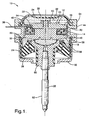
Figure 1 is a longitudinal cross-sectional schematic view of an embodiment of an MR-fluid (magnetorheological-fluid) hydraulic mount of the invention; and -
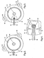
Figure 2 is a top planar view of the partition plate assembly and first and second coil leads ofFigure 1 ; -
Figure 3 is a view, as inFigure 2 , but with a portion broken away exposing the first and second terminal posts; and -
Figure 4 is an enlarged view of the broken away portion ofFigure 3 . - Referring now to the drawing,
Figures 1-4 show an embodiment of the present invention. A first expression of the embodiment ofFigures 1-4 is for an MR-fluid (magnetorheological-fluid)hydraulic mount 10 including a hydraulic-mountpartition plate assembly 12 and an electric coil 14. Thepartition plate assembly 12 has alongitudinal axis 22, has first andsecond sides orifice 20 extending substantially parallel to thelongitudinal axis 22 from thefirst side 16 to thesecond side 18. Thepartition plate assembly 12 is devoid of any non-MR-hydraulic-fluid orifice (whether a through orifice or a non-through orifice). The electric coil 14 is substantially coaxially aligned with thelongitudinal axis 22 and is adapted to magnetically influence the MR-fluid throughorifice 20. The MR-fluid throughorifice 20 is disposed radially outward of the electric coil 14. - In one embodiment as illustrated in
Figures 1-4 , the MR-fluidhydraulic mount 10, also includes a flexible, MR-fluid-sealing assembly 24. The MR-fluid-sealing assembly 24 has afirst portion 26 and asecond portion 28. Thefirst portion 26 is hermetically sealed to thefirst side 16 and surrounds the MR-fluid throughorifice 20. Thesecond portion 28 is hermetically sealed to thesecond side 18 and surrounds the MR-fluid throughorifice 20. - In one implementation of said the embodiment of
Figures 1-4 , the MR-fluid throughorifice 20 is, according to the invention, a substantially annular orifice substantially coaxially aligned with thelongitudinal axis 22, whereby, preferably, thesecond side 18 has a radially-outermost extent 30 adapted for contact withMR fluid 32, and the MR-fluid throughorifice 20 is disposed proximate the radially-outermost extent 30. In one variation, thesecond side 18 from thelongitudinal axis 22 to the radially-outermost extent 30 is adapted for contact with theMR fluid 32. In one modification, the partition-plate assembly 12 is devoid of any other MR-fluid through orifice. In one example, thepartition plate assembly 12 is devoid of any hydraulic-mount decoupler operatively connected to any MR-fluid through orifice. - In one application of said embodiment of
Figures 1-4 , thepartition plate assembly 12 includes first andsecond terminal posts hydraulic mount 10 also includes first and second coil leads 38 and 40 electrically connected, respectively, to the first andsecond terminal posts orifice 20 is a substantially annular orifice substantially coaxially aligned with thelongitudinal axis 22, thepartition plate assembly 12 includes aspoke 42 which crosses the substantially annular orifice, and thespoke 42 surrounds the first and second coil leads 38 and 40. In one example, thepartition plate assembly 12 includes anupper plate 44 and includes alower plate 46 in contact with theupper plate 44. In this example, the electric coil 14 is disposed in thelower plate 46, thelower plate 46 includes the first andsecond terminal posts upper plate 44 includes thespoke 42. In this example, the MR-fluidhydraulic mount 10 also includes an O-ring seal 48 disposed between the upper andlower plates second terminal posts - In one construction of said embodiment of
Figures 1-4 , the electric coil 14 is a plastic-encapsulated electric coil, and anut 50 secures theupper plate 44 to thelower plate 46 as shown inFigure 1 . In one variation, the MR-fluid hydraulic mount includes ametal base plate 52 surrounding the (e.g., rubber)first portion 26 of the MR-fluid-sealing assembly 24, and ametal ring 54 secures thebase plate 52 to theupper plate 44. In one modification, ametal housing 56 is attached to theupper plate 44 and surrounds the (e.g., rubber)second portion 28 of the MR-fluid-sealing assembly 24. In one example,metal inserts 58 in thesecond portion 28 are used to adjust the rate of the MR-fluidhydraulic mount 10. In one illustration, thesecond portion 28 surrounds a metal second-portion supporting member 60 secured to ametal mounting stud 62. In one configuration, thehousing 56 includesmounting holes 64. In one arrangement, thehousing 56 is attached to a motor-vehicle frame (not shown) and themounting stud 62 is attached to a motor-vehicle engine (not shown) which hangs from the MR-fluidhydraulic mount 10. Other constructions are left to those skilled in the art. - The embodiment of
Figures 1-4 shows an MR-fluid (magnetorheological-fluid)hydraulic mount 10 including a hydraulic-mountpartition plate assembly 12, an electric coil 14, and MR (magnetorheological)fluid 32. Thepartition plate assembly 12 has alongitudinal axis 22, has first andsecond sides orifice 20 extending substantially parallel to thelongitudinal axis 22 from thefirst side 16 to thesecond side 18. Thepartition plate assembly 12 is devoid of any non-MR-hydraulic-fluid orifice (whether a through orifice or a non-through orifice). The electric coil 14 is substantially coaxially aligned with thelongitudinal axis 22 and is adapted to magnetically influence the MR-fluid throughorifice 20. The MR-fluid throughorifice 20 is disposed radially outward of the electric coil 14. TheMR fluid 32 is disposed in the MR-fluid throughorifice 20 and is disposed in contact with the first andsecond sides hydraulic mount 10 is devoid of any non-MR hydraulic fluid. - In one enablement of said embodiment of
Figures 1-4 , the MR-fluidhydraulic mount 10, also includes a flexible, MR-fluid-sealing assembly 24. The MR-fluid-sealingassembly 24 has afirst portion 26 and asecond portion 28. Thefirst portion 26 is hermetically sealed to thefirst side 16 and surrounds the MR-fluid throughorifice 20. Thesecond portion 28 is hermetically sealed to thesecond side 18 and surrounds the MR-fluid throughorifice 20. TheMR fluid 32 is disposed in contact with the first andsecond portions - In one implementation of said embodiment of
Figures 1-4 , the MR-fluid throughorifice 20 is according to the invention a substantially annular orifice substantially coaxially aligned with thelongitudinal axis 22, whereby, preferably, thesecond side 18 has a radially-outermost extent 30 in contact with theMR fluid 32, and the MR-fluid throughorifice 20 is disposed proximate the radially-outermost extent 30. In one variation, thesecond side 18 from thelongitudinal axis 22 to the radially-outermost extent 30 is in contact with theMR fluid 32. In one modification, the partition-plate assembly 12 is devoid of any other MR-fluid through orifice. In one example, thepartition plate assembly 12 is devoid of any hydraulic-mount decoupler operatively connected to any MR-fluid through orifice. - In one application of said embodiment of
Figures 1-4 , thepartition plate assembly 12 includes first and secondterminal posts hydraulic mount 10 also includes first and second coil leads 38 and 40 electrically connected, respectively, to the first and secondterminal posts orifice 20 is a substantially annular orifice substantially coaxially aligned with thelongitudinal axis 22, thepartition plate assembly 12 includes aspoke 42 which crosses the substantially annular orifice, and thespoke 42 surrounds the first and second coil leads 38 and 40. In one example, thepartition plate assembly 12 includes anupper plate 44 and includes alower plate 46 in contact with theupper plate 44. In this example, the electric coil 14 is disposed in thelower plate 46, thelower plate 46 includes the first and secondterminal posts upper plate 44 includes thespoke 42. In this example, the MR-fluidhydraulic mount 10 also includes an O-ring seal 48 disposed between the upper andlower plates terminal posts - Several benefits and advantages are derived from the invention. In one embodiment, according to an additional feature of the invention as substantially disclosed in claim 3, the MR-fluid through orifice is a substantially annular orifice located at a substantially radially outermost location of the MR-fluid hydraulic mount which provides a larger orifice gap area for a given orifice gap distance, such larger orifice gap area allowing higher frequency off-current performance of the mount before the orifice gap becomes "choked off' and reduces the isolation of the mount, as can be appreciated by those skilled in the art.
- The foregoing description of several applications and enablements of an embodiment of the invention has been presented for purposes of illustration. It is not intended to be exhaustive or to limit the invention to the precise form disclosed, and obviously many modifications and variations are possible within the scope of the invention in the light of the above teaching. It is intended that the scope of the invention be defined by the claims appended hereto.
Claims (11)
- An MR-fluid hydraulic mount (10) comprising:a) a hydraulic-mount partition plate assembly (12) having a longitudinal axis (22), having first and second sides (16 and 18), and having an MR-fluid through orifice (20) extending substantially parallel to the longitudinal axis from the first side (16) to the second side (18), wherein the partition plate assembly (12) is devoid of any non-MR-hydraulic-fluid orifice; andb) an electric coil (14) substantially coaxially aligned with the longitudinal axis and adapted to magnetically influence the MR-fluid through orifice, characterised in that the MR-fluid through orifice (20) is a substantially annular orifice substantially coaxially aligned with the longitudinal axis and is disposed radially outward of the electric coil (14).
- The MR-fluid hydraulic mount of claim 1, also including a flexible, MR-fluid-sealing assembly (24) having a first portion (26) hermetically sealed to the first side and surrounding the MR-fluid through orifice and having a second portion (28) hermetically sealed to the second side and surrounding the MR-fluid through orifice, wherein the MR-fluid is disposed in contact with the first and second portions.
- The MR-fluid hydraulic mount of claim 2, wherein the second side has a radially-outermost extent (30) adapted for contact with MR-fluid (32), and wherein the MR-fluid through orifice is disposed proximate the radially-outermost extent.
- The MR-fluid hydraulic mount of claim 3, wherein the second side from the longitudinal axis to the radially-outermost extent is adapted for contact with the MR fluid.
- The MR-fluid hydraulic mount of claim 4, wherein the partition-plate assembly is devoid of any other MR-fluid through orifice.
- The MR-fluid hydraulic mount of claim 5, wherein the partition plate assembly is devoid of any hydraulic-mount decoupler operatively connected to any MR-fluid through orifice.
- The MR-fluid hydraulic mount of claim 1, wherein the partition plate assembly includes first and second terminal posts (34 and 36) in operative electrical connection with the electric coil.
- The MR-fluid hydraulic mount of claim 7, also including first and second coil leads (38 and 40) electrically connected, respectively, to the first and second terminal posts.
- The MR-fluid hydraulic mount of claim 8, wherein the MR-fluid through orifice is a substantially annular orifice substantially coaxially aligned with the longitudinal axis, wherein the partition plate assembly includes a spoke (42) which crosses the substantially annular orifice, and wherein the spoke surrounds the first and second coil leads.
- The MR-fluid hydraulic mount of claim 9, wherein the partition plate assembly includes an upper plate (44) and includes a lower plate (46) in contact with the upper plate, wherein the electric coil is disposed in the lower plate, wherein the lower plate includes the first and second terminal posts, wherein the upper plate includes the spoke, and also including an O-ring seal (48) disposed between the upper and lower plates and surrounding the first and second terminal posts.
- An MR-fluid hydraulic mount (10) as claimed in any one of claims 1 to 10, further comprising MR fluid (32) disposed in the MR-fluid through orifice and disposed in contact with the first and second sides, wherein the MR-fluid hydraulic mount is devoid of any non-MR hydraulic fluid.
Applications Claiming Priority (1)
| Application Number | Priority Date | Filing Date | Title |
|---|---|---|---|
| US11/319,109 US7510061B2 (en) | 2005-12-27 | 2005-12-27 | MR-fluid hydraulic mount |
Publications (3)
| Publication Number | Publication Date |
|---|---|
| EP1803961A2 EP1803961A2 (en) | 2007-07-04 |
| EP1803961A3 EP1803961A3 (en) | 2008-04-23 |
| EP1803961B1 true EP1803961B1 (en) | 2011-02-09 |
Family
ID=37890493
Family Applications (1)
| Application Number | Title | Priority Date | Filing Date |
|---|---|---|---|
| EP06077251A Not-in-force EP1803961B1 (en) | 2005-12-27 | 2006-12-14 | MR-fluid hydraulic mount |
Country Status (4)
| Country | Link |
|---|---|
| US (1) | US7510061B2 (en) |
| EP (1) | EP1803961B1 (en) |
| AT (1) | ATE498077T1 (en) |
| DE (1) | DE602006020011D1 (en) |
Families Citing this family (13)
| Publication number | Priority date | Publication date | Assignee | Title |
|---|---|---|---|---|
| FR2924189B1 (en) * | 2007-11-28 | 2010-07-30 | Peugeot Citroen Automobiles Sa | HYDRAULIC ANTI-VIBRATION DEVICE FOR MOTOR PROPELLER GROUP OF MOTOR VEHICLES |
| US20090273128A1 (en) * | 2008-05-01 | 2009-11-05 | Bodie Mark O | Apparatus including an MR-fluid hydraulic mount |
| CN103782057B (en) * | 2011-07-12 | 2016-04-13 | 北京京西重工有限公司 | Double-pump type magnetorheological hydraulic pull bar builtup member |
| US9341008B1 (en) | 2014-11-26 | 2016-05-17 | Brunswick Corporation | Hinge assemblies for a cowl of an outboard motor |
| CN105715802B (en) * | 2014-12-05 | 2018-03-27 | 长春孔辉汽车科技股份有限公司 | Magnetorheological pressure control valve |
| US9802688B1 (en) | 2014-12-17 | 2017-10-31 | Brunswick Corporation | Systems and methods for mounting a propulsion device with respect to a marine vessel |
| US10967946B1 (en) | 2014-12-17 | 2021-04-06 | Brunswick Corporation | Systems and methods for mounting a propulsion device with respect to a marine vessel |
| US9290252B1 (en) | 2015-01-12 | 2016-03-22 | Brunswick Corporation | Systems and methods for controlling trim position of a marine propulsion device on a marine vessel |
| KR101746581B1 (en) * | 2015-12-14 | 2017-06-27 | 현대자동차주식회사 | Roll-mount |
| US9969230B2 (en) * | 2016-04-11 | 2018-05-15 | Beijingwest Industries Co., Ltd. | Top mount assembly having adjustable damping characteristics |
| US10927922B2 (en) * | 2017-12-04 | 2021-02-23 | Vibracoustic North America L.P. | Hydraulic mount |
| JP2020139546A (en) * | 2019-02-27 | 2020-09-03 | 本田技研工業株式会社 | Variable rigidity anti-vibration device |
| CN118881673B (en) * | 2024-07-11 | 2025-09-19 | 岚图汽车科技有限公司 | Air spring assembly, suspension system and vehicle |
Family Cites Families (20)
| Publication number | Priority date | Publication date | Assignee | Title |
|---|---|---|---|---|
| US4679779A (en) * | 1986-06-17 | 1987-07-14 | General Motors Corporation | Hydraulic mount |
| US4861006A (en) * | 1986-09-16 | 1989-08-29 | Bridgestone Corporation | Anti-vibration apparatus |
| JPH0625727Y2 (en) * | 1988-08-23 | 1994-07-06 | 東海ゴム工業株式会社 | Fluid-filled mounting device |
| JPH03229032A (en) | 1990-02-03 | 1991-10-11 | Mazda Motor Corp | Engine mount device |
| US5273262A (en) * | 1992-06-15 | 1993-12-28 | General Motors Corporation | Hydraulic mount with low amplitude, low-to-medium frequency vibration isolation |
| US5284330A (en) * | 1992-06-18 | 1994-02-08 | Lord Corporation | Magnetorheological fluid devices |
| US5246211A (en) * | 1992-07-13 | 1993-09-21 | General Motors Corporation | Hydraulic mount with spring-loaded decoupler for tuned rate dip |
| US5730429A (en) * | 1993-10-29 | 1998-03-24 | Lord Corporation | Decouplers for active devices |
| US5878851A (en) * | 1996-07-02 | 1999-03-09 | Lord Corporation | Controllable vibration apparatus |
| GB2315167B (en) * | 1996-07-08 | 1999-04-21 | Amphenol Corp | Electrical connector and cable termination system |
| DE10001420A1 (en) * | 2000-01-15 | 2001-07-19 | Schenck Ag Carl | Passive force element based on electrorheological fluids |
| US20020153647A1 (en) * | 2001-04-23 | 2002-10-24 | Delphi Technologies Inc. | Hydraulic mount and control method |
| US6412761B1 (en) * | 2001-04-25 | 2002-07-02 | Delphi Technologies, Inc. | Hybrid hydraulic mount with magnetorheological fluid chamber |
| US6622995B2 (en) * | 2001-05-16 | 2003-09-23 | Delphi Technologies, Inc. | Hydraulic mount with magnetorheological fluid |
| US6754571B2 (en) * | 2001-07-30 | 2004-06-22 | Delphi Technologies, Inc. | Control of magnetorheological engine mount |
| JP2003065384A (en) | 2001-08-24 | 2003-03-05 | Toyo Tire & Rubber Co Ltd | Vibration absorber and liquid-filled vibration absorber |
| US6972500B2 (en) * | 2003-03-26 | 2005-12-06 | Keihin Corporation | Electromagnetic actuator |
| US7063191B2 (en) * | 2004-02-10 | 2006-06-20 | Delphi Technologies, Inc. | Reversed decoupler assembly for MR mount |
| US7118100B2 (en) * | 2004-04-16 | 2006-10-10 | Delphi Technologies, Inc. | Magnetorheological-fluid hydraulic mount |
| US7070708B2 (en) * | 2004-04-30 | 2006-07-04 | Delphi Technologies, Inc. | Magnetorheological fluid resistant to settling in natural rubber devices |
-
2005
- 2005-12-27 US US11/319,109 patent/US7510061B2/en not_active Expired - Lifetime
-
2006
- 2006-12-14 AT AT06077251T patent/ATE498077T1/en not_active IP Right Cessation
- 2006-12-14 EP EP06077251A patent/EP1803961B1/en not_active Not-in-force
- 2006-12-14 DE DE602006020011T patent/DE602006020011D1/en active Active
Also Published As
| Publication number | Publication date |
|---|---|
| EP1803961A2 (en) | 2007-07-04 |
| US20070144843A1 (en) | 2007-06-28 |
| US7510061B2 (en) | 2009-03-31 |
| ATE498077T1 (en) | 2011-02-15 |
| EP1803961A3 (en) | 2008-04-23 |
| DE602006020011D1 (en) | 2011-03-24 |
Similar Documents
| Publication | Publication Date | Title |
|---|---|---|
| US7510061B2 (en) | MR-fluid hydraulic mount | |
| US7188830B2 (en) | Fluid-filled active damping apparatus | |
| US8172209B2 (en) | Fluid filled type vibration damping device | |
| US7537202B2 (en) | Active vibration damping device | |
| EP2732182B1 (en) | A hydraulic mount apparatus for supporting vibration source | |
| US8047513B2 (en) | Fluid filled type vibration damping device | |
| US20080174058A1 (en) | Fluid filled type engine mount | |
| EP0754878A1 (en) | Vibration isolating apparatus | |
| JPH11102813A (en) | Electromagnetic actuator | |
| EP1586790B1 (en) | Magnetorheological-fluid hydraulic mount | |
| JP5154213B2 (en) | Fluid filled vibration isolator | |
| JP2008202779A (en) | Fluid filled engine mount | |
| JPH09309345A (en) | Hydraulic vibration control device | |
| US7128311B2 (en) | Active vibration damping actuator and active damping apparatus using the same | |
| EP3620683B1 (en) | Mr mount apparatus using a polymeric sheet decoupler | |
| US6863269B2 (en) | Fluid filled vibration damping device | |
| JPH0989040A (en) | Fluid-filled vibration isolator | |
| JP3619056B2 (en) | Active vibration isolator | |
| JP2006308054A (en) | Anti-vibration actuator and active vibration isolator using the same | |
| JP2006275273A (en) | Fluid-filled engine mount for automobiles and power unit support mechanism using the same | |
| JP5038124B2 (en) | Fluid filled vibration isolator | |
| JP3777784B2 (en) | Cylindrical fluid-filled mounting device | |
| JP5154212B2 (en) | Fluid filled vibration isolator | |
| JP5002176B2 (en) | Electromagnetic active mount | |
| JP2008133937A (en) | Fluid filled vibration isolator |
Legal Events
| Date | Code | Title | Description |
|---|---|---|---|
| PUAI | Public reference made under article 153(3) epc to a published international application that has entered the european phase |
Free format text: ORIGINAL CODE: 0009012 |
|
| AK | Designated contracting states |
Kind code of ref document: A2 Designated state(s): AT BE BG CH CY CZ DE DK EE ES FI FR GB GR HU IE IS IT LI LT LU LV MC NL PL PT RO SE SI SK TR |
|
| AX | Request for extension of the european patent |
Extension state: AL BA HR MK YU |
|
| PUAL | Search report despatched |
Free format text: ORIGINAL CODE: 0009013 |
|
| AK | Designated contracting states |
Kind code of ref document: A3 Designated state(s): AT BE BG CH CY CZ DE DK EE ES FI FR GB GR HU IE IS IT LI LT LU LV MC NL PL PT RO SE SI SK TR |
|
| AX | Request for extension of the european patent |
Extension state: AL BA HR MK RS |
|
| 17P | Request for examination filed |
Effective date: 20081023 |
|
| 17Q | First examination report despatched |
Effective date: 20081124 |
|
| AKX | Designation fees paid |
Designated state(s): AT BE BG CH CY CZ DE DK EE ES FI FR GB GR HU IE IS IT LI LT LU LV MC NL PL PT RO SE SI SK TR |
|
| GRAP | Despatch of communication of intention to grant a patent |
Free format text: ORIGINAL CODE: EPIDOSNIGR1 |
|
| GRAS | Grant fee paid |
Free format text: ORIGINAL CODE: EPIDOSNIGR3 |
|
| GRAA | (expected) grant |
Free format text: ORIGINAL CODE: 0009210 |
|
| AK | Designated contracting states |
Kind code of ref document: B1 Designated state(s): AT BE BG CH CY CZ DE DK EE ES FI FR GB GR HU IE IS IT LI LT LU LV MC NL PL PT RO SE SI SK TR |
|
| REG | Reference to a national code |
Ref country code: GB Ref legal event code: FG4D |
|
| REG | Reference to a national code |
Ref country code: CH Ref legal event code: EP |
|
| REG | Reference to a national code |
Ref country code: IE Ref legal event code: FG4D |
|
| REF | Corresponds to: |
Ref document number: 602006020011 Country of ref document: DE Date of ref document: 20110324 Kind code of ref document: P |
|
| REG | Reference to a national code |
Ref country code: DE Ref legal event code: R096 Ref document number: 602006020011 Country of ref document: DE Effective date: 20110324 |
|
| REG | Reference to a national code |
Ref country code: NL Ref legal event code: VDEP Effective date: 20110209 |
|
| LTIE | Lt: invalidation of european patent or patent extension |
Effective date: 20110209 |
|
| PG25 | Lapsed in a contracting state [announced via postgrant information from national office to epo] |
Ref country code: GR Free format text: LAPSE BECAUSE OF FAILURE TO SUBMIT A TRANSLATION OF THE DESCRIPTION OR TO PAY THE FEE WITHIN THE PRESCRIBED TIME-LIMIT Effective date: 20110510 Ref country code: PT Free format text: LAPSE BECAUSE OF FAILURE TO SUBMIT A TRANSLATION OF THE DESCRIPTION OR TO PAY THE FEE WITHIN THE PRESCRIBED TIME-LIMIT Effective date: 20110609 Ref country code: SE Free format text: LAPSE BECAUSE OF FAILURE TO SUBMIT A TRANSLATION OF THE DESCRIPTION OR TO PAY THE FEE WITHIN THE PRESCRIBED TIME-LIMIT Effective date: 20110209 Ref country code: LV Free format text: LAPSE BECAUSE OF FAILURE TO SUBMIT A TRANSLATION OF THE DESCRIPTION OR TO PAY THE FEE WITHIN THE PRESCRIBED TIME-LIMIT Effective date: 20110209 Ref country code: LT Free format text: LAPSE BECAUSE OF FAILURE TO SUBMIT A TRANSLATION OF THE DESCRIPTION OR TO PAY THE FEE WITHIN THE PRESCRIBED TIME-LIMIT Effective date: 20110209 Ref country code: ES Free format text: LAPSE BECAUSE OF FAILURE TO SUBMIT A TRANSLATION OF THE DESCRIPTION OR TO PAY THE FEE WITHIN THE PRESCRIBED TIME-LIMIT Effective date: 20110520 |
|
| PG25 | Lapsed in a contracting state [announced via postgrant information from national office to epo] |
Ref country code: NL Free format text: LAPSE BECAUSE OF FAILURE TO SUBMIT A TRANSLATION OF THE DESCRIPTION OR TO PAY THE FEE WITHIN THE PRESCRIBED TIME-LIMIT Effective date: 20110209 Ref country code: PL Free format text: LAPSE BECAUSE OF FAILURE TO SUBMIT A TRANSLATION OF THE DESCRIPTION OR TO PAY THE FEE WITHIN THE PRESCRIBED TIME-LIMIT Effective date: 20110209 Ref country code: BG Free format text: LAPSE BECAUSE OF FAILURE TO SUBMIT A TRANSLATION OF THE DESCRIPTION OR TO PAY THE FEE WITHIN THE PRESCRIBED TIME-LIMIT Effective date: 20110509 Ref country code: FI Free format text: LAPSE BECAUSE OF FAILURE TO SUBMIT A TRANSLATION OF THE DESCRIPTION OR TO PAY THE FEE WITHIN THE PRESCRIBED TIME-LIMIT Effective date: 20110209 Ref country code: SI Free format text: LAPSE BECAUSE OF FAILURE TO SUBMIT A TRANSLATION OF THE DESCRIPTION OR TO PAY THE FEE WITHIN THE PRESCRIBED TIME-LIMIT Effective date: 20110209 Ref country code: CY Free format text: LAPSE BECAUSE OF FAILURE TO SUBMIT A TRANSLATION OF THE DESCRIPTION OR TO PAY THE FEE WITHIN THE PRESCRIBED TIME-LIMIT Effective date: 20110209 Ref country code: AT Free format text: LAPSE BECAUSE OF FAILURE TO SUBMIT A TRANSLATION OF THE DESCRIPTION OR TO PAY THE FEE WITHIN THE PRESCRIBED TIME-LIMIT Effective date: 20110209 Ref country code: BE Free format text: LAPSE BECAUSE OF FAILURE TO SUBMIT A TRANSLATION OF THE DESCRIPTION OR TO PAY THE FEE WITHIN THE PRESCRIBED TIME-LIMIT Effective date: 20110209 |
|
| PG25 | Lapsed in a contracting state [announced via postgrant information from national office to epo] |
Ref country code: DK Free format text: LAPSE BECAUSE OF FAILURE TO SUBMIT A TRANSLATION OF THE DESCRIPTION OR TO PAY THE FEE WITHIN THE PRESCRIBED TIME-LIMIT Effective date: 20110209 Ref country code: EE Free format text: LAPSE BECAUSE OF FAILURE TO SUBMIT A TRANSLATION OF THE DESCRIPTION OR TO PAY THE FEE WITHIN THE PRESCRIBED TIME-LIMIT Effective date: 20110209 |
|
| PG25 | Lapsed in a contracting state [announced via postgrant information from national office to epo] |
Ref country code: RO Free format text: LAPSE BECAUSE OF FAILURE TO SUBMIT A TRANSLATION OF THE DESCRIPTION OR TO PAY THE FEE WITHIN THE PRESCRIBED TIME-LIMIT Effective date: 20110209 Ref country code: CZ Free format text: LAPSE BECAUSE OF FAILURE TO SUBMIT A TRANSLATION OF THE DESCRIPTION OR TO PAY THE FEE WITHIN THE PRESCRIBED TIME-LIMIT Effective date: 20110209 Ref country code: SK Free format text: LAPSE BECAUSE OF FAILURE TO SUBMIT A TRANSLATION OF THE DESCRIPTION OR TO PAY THE FEE WITHIN THE PRESCRIBED TIME-LIMIT Effective date: 20110209 |
|
| PLBE | No opposition filed within time limit |
Free format text: ORIGINAL CODE: 0009261 |
|
| STAA | Information on the status of an ep patent application or granted ep patent |
Free format text: STATUS: NO OPPOSITION FILED WITHIN TIME LIMIT |
|
| 26N | No opposition filed |
Effective date: 20111110 |
|
| REG | Reference to a national code |
Ref country code: DE Ref legal event code: R097 Ref document number: 602006020011 Country of ref document: DE Effective date: 20111110 |
|
| PG25 | Lapsed in a contracting state [announced via postgrant information from national office to epo] |
Ref country code: IT Free format text: LAPSE BECAUSE OF FAILURE TO SUBMIT A TRANSLATION OF THE DESCRIPTION OR TO PAY THE FEE WITHIN THE PRESCRIBED TIME-LIMIT Effective date: 20110209 |
|
| PG25 | Lapsed in a contracting state [announced via postgrant information from national office to epo] |
Ref country code: MC Free format text: LAPSE BECAUSE OF NON-PAYMENT OF DUE FEES Effective date: 20111231 |
|
| REG | Reference to a national code |
Ref country code: CH Ref legal event code: PL |
|
| REG | Reference to a national code |
Ref country code: IE Ref legal event code: MM4A |
|
| PG25 | Lapsed in a contracting state [announced via postgrant information from national office to epo] |
Ref country code: CH Free format text: LAPSE BECAUSE OF NON-PAYMENT OF DUE FEES Effective date: 20111231 Ref country code: IE Free format text: LAPSE BECAUSE OF NON-PAYMENT OF DUE FEES Effective date: 20111214 Ref country code: LI Free format text: LAPSE BECAUSE OF NON-PAYMENT OF DUE FEES Effective date: 20111231 |
|
| PG25 | Lapsed in a contracting state [announced via postgrant information from national office to epo] |
Ref country code: LU Free format text: LAPSE BECAUSE OF NON-PAYMENT OF DUE FEES Effective date: 20111214 |
|
| PG25 | Lapsed in a contracting state [announced via postgrant information from national office to epo] |
Ref country code: IS Free format text: LAPSE BECAUSE OF FAILURE TO SUBMIT A TRANSLATION OF THE DESCRIPTION OR TO PAY THE FEE WITHIN THE PRESCRIBED TIME-LIMIT Effective date: 20110209 |
|
| PG25 | Lapsed in a contracting state [announced via postgrant information from national office to epo] |
Ref country code: TR Free format text: LAPSE BECAUSE OF FAILURE TO SUBMIT A TRANSLATION OF THE DESCRIPTION OR TO PAY THE FEE WITHIN THE PRESCRIBED TIME-LIMIT Effective date: 20110209 |
|
| PG25 | Lapsed in a contracting state [announced via postgrant information from national office to epo] |
Ref country code: HU Free format text: LAPSE BECAUSE OF FAILURE TO SUBMIT A TRANSLATION OF THE DESCRIPTION OR TO PAY THE FEE WITHIN THE PRESCRIBED TIME-LIMIT Effective date: 20110209 |
|
| REG | Reference to a national code |
Ref country code: FR Ref legal event code: PLFP Year of fee payment: 10 |
|
| REG | Reference to a national code |
Ref country code: FR Ref legal event code: PLFP Year of fee payment: 11 |
|
| REG | Reference to a national code |
Ref country code: FR Ref legal event code: PLFP Year of fee payment: 12 |
|
| PGFP | Annual fee paid to national office [announced via postgrant information from national office to epo] |
Ref country code: GB Payment date: 20221103 Year of fee payment: 17 Ref country code: FR Payment date: 20221110 Year of fee payment: 17 Ref country code: DE Payment date: 20221102 Year of fee payment: 17 |
|
| REG | Reference to a national code |
Ref country code: DE Ref legal event code: R119 Ref document number: 602006020011 Country of ref document: DE |
|
| GBPC | Gb: european patent ceased through non-payment of renewal fee |
Effective date: 20231214 |
|
| PG25 | Lapsed in a contracting state [announced via postgrant information from national office to epo] |
Ref country code: DE Free format text: LAPSE BECAUSE OF NON-PAYMENT OF DUE FEES Effective date: 20240702 |
|
| PG25 | Lapsed in a contracting state [announced via postgrant information from national office to epo] |
Ref country code: GB Free format text: LAPSE BECAUSE OF NON-PAYMENT OF DUE FEES Effective date: 20231214 |
|
| PG25 | Lapsed in a contracting state [announced via postgrant information from national office to epo] |
Ref country code: FR Free format text: LAPSE BECAUSE OF NON-PAYMENT OF DUE FEES Effective date: 20231231 |
|
| PG25 | Lapsed in a contracting state [announced via postgrant information from national office to epo] |
Ref country code: GB Free format text: LAPSE BECAUSE OF NON-PAYMENT OF DUE FEES Effective date: 20231214 Ref country code: FR Free format text: LAPSE BECAUSE OF NON-PAYMENT OF DUE FEES Effective date: 20231231 Ref country code: DE Free format text: LAPSE BECAUSE OF NON-PAYMENT OF DUE FEES Effective date: 20240702 |