EP1803941A1 - Turbo machine, compressor impeller used for turbo machine, and method of manufacturing turbo machine - Google Patents
Turbo machine, compressor impeller used for turbo machine, and method of manufacturing turbo machine Download PDFInfo
- Publication number
- EP1803941A1 EP1803941A1 EP05795829A EP05795829A EP1803941A1 EP 1803941 A1 EP1803941 A1 EP 1803941A1 EP 05795829 A EP05795829 A EP 05795829A EP 05795829 A EP05795829 A EP 05795829A EP 1803941 A1 EP1803941 A1 EP 1803941A1
- Authority
- EP
- European Patent Office
- Prior art keywords
- drive shaft
- compressor impeller
- turbo machine
- fit
- sleeve
- Prior art date
- Legal status (The legal status is an assumption and is not a legal conclusion. Google has not performed a legal analysis and makes no representation as to the accuracy of the status listed.)
- Withdrawn
Links
Images


Classifications
-
- F—MECHANICAL ENGINEERING; LIGHTING; HEATING; WEAPONS; BLASTING
- F01—MACHINES OR ENGINES IN GENERAL; ENGINE PLANTS IN GENERAL; STEAM ENGINES
- F01D—NON-POSITIVE DISPLACEMENT MACHINES OR ENGINES, e.g. STEAM TURBINES
- F01D5/00—Blades; Blade-carrying members; Heating, heat-insulating, cooling or antivibration means on the blades or the members
- F01D5/02—Blade-carrying members, e.g. rotors
- F01D5/026—Shaft to shaft connections
-
- F—MECHANICAL ENGINEERING; LIGHTING; HEATING; WEAPONS; BLASTING
- F04—POSITIVE - DISPLACEMENT MACHINES FOR LIQUIDS; PUMPS FOR LIQUIDS OR ELASTIC FLUIDS
- F04D—NON-POSITIVE-DISPLACEMENT PUMPS
- F04D29/00—Details, component parts, or accessories
- F04D29/26—Rotors specially for elastic fluids
- F04D29/28—Rotors specially for elastic fluids for centrifugal or helico-centrifugal pumps for radial-flow or helico-centrifugal pumps
- F04D29/30—Vanes
-
- F—MECHANICAL ENGINEERING; LIGHTING; HEATING; WEAPONS; BLASTING
- F01—MACHINES OR ENGINES IN GENERAL; ENGINE PLANTS IN GENERAL; STEAM ENGINES
- F01D—NON-POSITIVE DISPLACEMENT MACHINES OR ENGINES, e.g. STEAM TURBINES
- F01D5/00—Blades; Blade-carrying members; Heating, heat-insulating, cooling or antivibration means on the blades or the members
- F01D5/02—Blade-carrying members, e.g. rotors
- F01D5/025—Fixing blade carrying members on shafts
-
- F—MECHANICAL ENGINEERING; LIGHTING; HEATING; WEAPONS; BLASTING
- F01—MACHINES OR ENGINES IN GENERAL; ENGINE PLANTS IN GENERAL; STEAM ENGINES
- F01D—NON-POSITIVE DISPLACEMENT MACHINES OR ENGINES, e.g. STEAM TURBINES
- F01D5/00—Blades; Blade-carrying members; Heating, heat-insulating, cooling or antivibration means on the blades or the members
- F01D5/02—Blade-carrying members, e.g. rotors
- F01D5/027—Arrangements for balancing
-
- F—MECHANICAL ENGINEERING; LIGHTING; HEATING; WEAPONS; BLASTING
- F04—POSITIVE - DISPLACEMENT MACHINES FOR LIQUIDS; PUMPS FOR LIQUIDS OR ELASTIC FLUIDS
- F04D—NON-POSITIVE-DISPLACEMENT PUMPS
- F04D25/00—Pumping installations or systems
- F04D25/02—Units comprising pumps and their driving means
- F04D25/04—Units comprising pumps and their driving means the pump being fluid-driven
-
- F—MECHANICAL ENGINEERING; LIGHTING; HEATING; WEAPONS; BLASTING
- F04—POSITIVE - DISPLACEMENT MACHINES FOR LIQUIDS; PUMPS FOR LIQUIDS OR ELASTIC FLUIDS
- F04D—NON-POSITIVE-DISPLACEMENT PUMPS
- F04D29/00—Details, component parts, or accessories
- F04D29/26—Rotors specially for elastic fluids
- F04D29/266—Rotors specially for elastic fluids mounting compressor rotors on shafts
-
- F—MECHANICAL ENGINEERING; LIGHTING; HEATING; WEAPONS; BLASTING
- F04—POSITIVE - DISPLACEMENT MACHINES FOR LIQUIDS; PUMPS FOR LIQUIDS OR ELASTIC FLUIDS
- F04D—NON-POSITIVE-DISPLACEMENT PUMPS
- F04D29/00—Details, component parts, or accessories
- F04D29/26—Rotors specially for elastic fluids
- F04D29/28—Rotors specially for elastic fluids for centrifugal or helico-centrifugal pumps for radial-flow or helico-centrifugal pumps
-
- F—MECHANICAL ENGINEERING; LIGHTING; HEATING; WEAPONS; BLASTING
- F05—INDEXING SCHEMES RELATING TO ENGINES OR PUMPS IN VARIOUS SUBCLASSES OF CLASSES F01-F04
- F05D—INDEXING SCHEME FOR ASPECTS RELATING TO NON-POSITIVE-DISPLACEMENT MACHINES OR ENGINES, GAS-TURBINES OR JET-PROPULSION PLANTS
- F05D2220/00—Application
- F05D2220/40—Application in turbochargers
-
- F—MECHANICAL ENGINEERING; LIGHTING; HEATING; WEAPONS; BLASTING
- F05—INDEXING SCHEMES RELATING TO ENGINES OR PUMPS IN VARIOUS SUBCLASSES OF CLASSES F01-F04
- F05D—INDEXING SCHEME FOR ASPECTS RELATING TO NON-POSITIVE-DISPLACEMENT MACHINES OR ENGINES, GAS-TURBINES OR JET-PROPULSION PLANTS
- F05D2300/00—Materials; Properties thereof
- F05D2300/50—Intrinsic material properties or characteristics
- F05D2300/502—Thermal properties
- F05D2300/5021—Expansivity
- F05D2300/50212—Expansivity dissimilar
Definitions
- the present invention relates to a turbo machine, a compressor impeller used for the turbo machine, and a method of manufacturing the turbo machine.
- the compressor impeller of a turbo machine such as a turbocharger
- the compressor impeller is fixed to a drive shaft provided integrally with a turbine by means of a nut. That is, the compressor impeller has an axially extending through-hole, into which the drive shaft is inserted, and the nut is threadedly engaged with a screw portion provided on the distal end portion of the drive shaft, and fastened for fixation.
- the compressor impeller is provided with a through-hole, high stress is liable to be generated at some midpoint in the axial direction thereof, and there is a limit to an improvement in terms of durability.
- connection structure in which the compressor impeller is provided with, in stead of a through-hole, a bottomed screw hole (blind hole) extending in the axial direction, and in which the drive shaft is threadedly engaged with this screw hole (See, for example, Patent Document 1 and Patent Document 2).
- a fit-engagement portion realized through interference fit of the drive shaft with the hole in order to eliminate back-lash in the threaded-engagement portion and to achieve an improvement in terms of concentricity.
- the screw hole it is only necessary for the screw hole to be long enough to ensure reliable threaded engagement of the drive shaft, and there is no need for it to extend to a midpoint in the axial direction, so that generation of high stress is not easily involved.
- a turbo machine includes: a compressor impeller having a projected portion at a center of a rear surface; a drive shaft fit-engaged with a bottomed coupling hole provided in the projected portion of the compressor impeller; and a cylindrical member fitted onto an outer peripheral portion of the projected portion corresponding to a fit-engaged portion of the drive shaft concentrically with the drive shaft.
- a turbo machine according to a second invention is characterized in that: in the turbo machine according to the first invention, the fit-engagement of the bottomed coupling hole of the projected portion and the drive shaft is effected through interference fit as defined in JIS B 0401; and the fit-engagement of the projected portion and the cylindrical member is effected through transition fit or clearance fit as defined in JIS B 0401.
- the interference fit can be realized by fit-engaging a bottomed hole with a shaft whose diameter is larger than the hole diameter by approximately 10% by press-fitting, forcible press-fitting, shrinkage fit, expansion fit, etc.
- the transition fit can be realized by fit-engaging the cylindrical member with the projected portion by slide fit, forcing-in, driving fit, etc. More specifically, it is possible to adopt, as appropriate, interference fit, transition fit, or clearance fit by selecting the shaft diameter tolerance range class as shown in Table 1 when the hole diameter is 6 mm to 10 mm.
- a turbo machine according to a third invention is characterized in that: in the turbo machine according to the first or second invention, the cylindrical member is formed of a material whose coefficient of linear expansion is smaller than that of the compressor impeller.
- the material of the compressor impeller it is possible to adopt, for example, aluminum (coefficient of linear expansion: 23.9 x 10 -6 1/C°) and duralumin (coefficient of linear expansion: 27.3 x 10 -6 1/C°).
- the material of the cylindrical member it is possible to adopt, for example, carbon steel (coefficient of linear expansion: 10.1 to 12.1 x 10 -6 1/C°), chromium steel (coefficient of linear expansion: 9.5 to 11.3 x 10 -6 1/C°), nickel steel (coefficient of linear expansion: 18.0 x 10 -6 1/C°), etc.
- a turbo machine according to a fourth invention is characterized in that: in the turbo machine according to any one of the first through the third inventions, the drive shaft is provided with a step-like shoulder portion; and a sleeve fitted onto the drive shaft is held between the shoulder portion and the compressor impeller.
- a turbo machine according to a fifth invention is characterized in that: in the turbo machine according to the fourth invention, the sleeve is held between the shoulder portion of the drive shaft and the compressor impeller while bearing axial contact pressure.
- a turbo machine according to a sixth invention is characterized in that: in the turbo machine according to the fourth or fifth invention, the cylindrical member is integrally provided on the sleeve.
- a turbo compressor according to a seventh invention is characterized in that the turbo machine according to any one of the fourth through the sixth inventions further includes: a housing rotatably supporting the drive shaft; a thrust collar fixed to the drive shaft; and a thrust bearing held between the thrust collar and the sleeve and fixed to the housing.
- a turbo machine according to an eighth invention is characterized in that: in the turbo machine according to the seventh invention, the sleeve is equipped with a seal means effecting sealing on lubricating oil and high pressure air between the sleeve and a housing.
- a turbo machine according to a ninth invention is characterized in that: in the turbo machine according to any one of the fourth through the eighth inventions, the sleeve and the drive shaft are provided with a first slippage suppressing means suppressing slippage in a rotating direction through mutual engagement.
- a turbo machine according to a tenth invention is characterized in that: in the turbo machine according to any one of the first through the ninth inventions, the annular member and the compressor impeller are provided with a second slippage suppressing means suppressing slippage in a rotating direction through mutual engagement.
- a turbo machine according to an eleventh invention is characterized in that: in the turbo machine according to any one of the first through the tenth inventions, the compressor impeller and the drive shaft are provided with a third slippage suppressing means suppressing slippage in a rotating direction through mutual engagement.
- a turbo machine according to a twelfth invention is characterized in that, in the turbo machine according to any one of the first through the eleventh inventions, the compressor impeller is equipped with an attachment/detachment means facilitating cancellation the fit-engagement of the drive shaft and the bottomed hole and the fit-engagement of the outer peripheral portion of the projected portion and the cylindrical member.
- the attachment/detachment means may be provided along the drive shaft connected to the compressor impeller and on the side opposite to the projected portion of the compressor impeller; for example, the attachment/detachment means may be formed by a female screw hole, a male screw, and a boss.
- a compressor impeller according to a thirteenth invention for use in a turbo machine includes a cylindrical projected portion projected from a central portion of a rear surface, characterized in that an inner peripheral portion and an outer peripheral portion of the projected portion respectively constitute a first connecting portion and a second connecting portion for incorporation into the turbo machine.
- a fourteenth invention there is provided a method of manufacturing a turbo machine which includes: a compressor impeller having a projected portion at a center of a rear surface; a drive shaft fit-engaged with a bottomed coupling hole provided in the projected portion of the compressor impeller; a housing rotatably supporting the drive shaft; and a cylindrical member fitted onto an outer peripheral portion of the projected portion corresponding to the fit-engaged portion of the drive shaft concentrically with the drive shaft.
- the method includes the steps of: inserting the drive shaft into the housing to cause a distal end of the drive shaft to be exposed through the housing; fitting the cylindrical member onto the drive shaft; and press-fitting the distal end of the drive shaft into the coupling hole of the compressor impeller and press-fitting the cylindrical member onto the projected portion.
- the drive shaft is fit-engaged with the projected portion of the compressor impeller; the cylindrical member is fit-engaged with the outer periphery of this projected portion, so that even when the drive shaft and the compressor impeller attain high temperature as a result of the driving of the turbo machine, and the compressor impeller expands and the fit-engagement of the drive shaft is loosened, the fit-engagement of the cylindrical member on the outer peripheral side is enhanced, thus preventing the drive shaft from being easily detached from the projected portion of the compressor impeller and making it possible to reliably attain an improvement in terms of durability.
- the fit-engagement of the bottomed coupling hole of the projected portion and the drive shaft is effected through interference fit
- the fit-engagement of the projected portion and the cylindrical member is effected through transition fit or clearance fit, so that, even when press-fitting, etc. of the drive shaft into the bottomed coupling hole is effected to expand the outer periphery of the projected portion, it is possible to reliably fit-engage the cylindrical member with the outer periphery of the projected portion since the fit-engagement between the projected portion and cylindrical member is loosened.
- the cylindrical member is formed of a material whose coefficient of linear expansion is smaller than that of the compressor impeller, whereby, even if the compressor impeller attains high temperature and expands, the fit-engagement in the outer periphery is further tightened since the expansion of the cylindrical member as a result of the increase in temperature is smaller than that of the compressor impeller, making it possible to maintain a firm fit-engagement between the drive shaft and the compressor impeller.
- the compressor impeller, the sleeve, etc. it is possible to arrange the compressor impeller, the sleeve, etc. at appropriate axial positions on the drive shaft.
- the sleeve is held between the compressor impeller and the shoulder portion while bearing a contact pressure, so that it is possible to rotate the sleeve reliably together with the drive shaft.
- the cylindrical member is provided integrally with the sleeve, so that it is possible to reduce the number of components and assemblage man-hours.
- the thrust bearing is held between the sleeve and the thrust collar, so that it is possible to reliably prevent the drive shaft from being axially deviated through the sleeve and the thrust collar. Further, due to the construction in which the thrust bearing is held between two components, unlike the construction in which a peripheral groove is provided in the sleeve and in which a horse-shoe-shaped thrust bearing is arranged in this groove, it is possible to use an annular thrust bearing, making it possible to support the rotating surface over the entire periphery in a well-balanced manner.
- the sleeve is provided with a seal means for sealing up lubricating oil and high pressure air, so that there is no fear of the high pressure supply air on the compressor impeller side entering the lubricated portion of the drive shaft and leaking therethrough, or the lubricating oil in the lubricated portion leaking out to the supercharged air side to get mixed therein.
- the sleeve and the drive shaft are provided with the first slippage suppressing means, so that it is possible to integrally rotate the sleeve and the drive shaft, making it possible to prevent seizure or the like from occurring therebetween.
- the cylindrical member and the compressor impeller are provided with the second slippage suppressing means, and the compressor impeller and the drive shaft are provided with the third slippage suppressing means, so that, as compared with the case in which the connection is effected through mutual fitting only, the burden on the connection surfaces can be mitigated, making it possible to reliably cope with slippage.
- the compressor impeller is provided with the attachment/detachment means, whereby it is possible to easily cancel the fit-engagement between the compressor impeller and the drive shaft by using the attachment/detachment means, so that it is possible to perform repair easily at the time of failure.
- the compressor impeller is incorporated into the turbo machine by utilizing the connecting portions of both the outer peripheral portion and the inner peripheral portion of the projected portion, so that, as compared with the prior-art technique, in which the connection is effected by utilizing the inner peripheral portion, it is possible to enhance the connection strength, making it possible to achieve an improvement in terms of durability.
- turbocharger turbo machine
- 13 turbocharger
- 15 ... drive shaft
- 16 housing (non-rotating member)
- 18 ... shoulder portion
- 19 projected portion
- 19A second connecting portion
- 20 coupling hole
- 20A first connecting portion
- 30 ... sleeve
- 31 ... thrust collar
- 32 ... thrust bearing
- 33 ... cylindrical portion (cylindrical member)
- 34 ... seal ring (seal means)
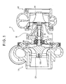
- Fig. 1 is a sectional view of a turbocharger (turbo machine) 1 according to the first embodiment of the present invention
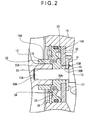
- Fig. 2 is a sectional view of a main portion of the turbocharger 1.
- the turbocharger 1 which is to be mounted, for example, in a gasoline engine or a diesel engine, is equipped with a compressor 11 connected to a midpoint of an intake pipe leading to an engine (not shown), and an exhaust turbine 12 connected to a midpoint of an exhaust pipe.
- the compressor 11 has a compressor impeller 13 for compressing intake air from the outside through rotation.
- the compressor impeller 13 has a hub substantially circular in front view and a plurality of vanes mounted thereto so as to be arranged in the rotating direction of the hub, and is formed of aluminum alloy casting.
- a female screw hole 131 is formed as an attachment/detachment means.
- the female screw hole 131 is used when they are to be separated from each other again. In this embodiment, it is provided in order to facilitate the separation, which is effected by threadedly engaging a removing tool (not shown) with the female screw 131 and pulling the removing tool.
- the exhaust turbine 12 has a turbine wheel 14, which is rotated by exhaust gas that flows in; the turbine wheel 14 is formed integrally with the steel drive shaft 15 by friction welding, TIG welding, MIG welding or the like.
- the drive shaft 15 is rotatably supported by a full float bearing 17 provided in a housing 16, with the compressor impeller 13 being connected to the distal end of the drive shaft 15.
- the connecting portion between the compressor impeller 13 and the drive shaft 15 will be described in detail.
- a projected portion 19 projected toward the turbine wheel 14 side.
- a coupling hole 20 extending axially toward the depth side thereof.
- the drive shaft 15 is to be inserted into the coupling hole 20 for connection; unlike the conventional coupling hole, which is a through-hole extending through the compressor impeller 13, the coupling hole 20 is a bottomed hole.
- the inner peripheral portion of the coupling hole 20 constitutes a first connecting portion 20A to be connected with the drive shaft 15.
- a fit-engagement shaft portion 15A to be inserted into the coupling hole 20 of the compressor impeller 13 and fit-engaged with the first connecting portion 20A thereof; on the proximal end side with respect to the fit-engagement shaft portion 15A, there is provided an insert portion 15B onto which a sleeve 30 is to be fitted.
- the fit-engagement between the fit-engagement shaft portion 15A and the first connecting portion 20A is effected through interference fit on a hole basis (e.g., H6/u6 in terms of JIS fit symbol). No other fixation structure such as a conventional one using a screw is adopted; the connection is effected solely through fit-engagement between the compressor impeller 13 and the drive shaft 15.
- the sleeve 30 is formed of a substantially cylindrical member that is open on the compressor impeller 13 side; it is formed of steel, whose coefficient of linear expansion is smaller than that of the compressor impeller 13, which is formed of aluminum.
- the sleeve 30 is equipped with an insertion hole 30A into which the drive shaft 15 is to be inserted; on the compressor impeller 13 side with respect to the insertion hole 30A, there is integrally provided a cylindrical portion (cylindrical member) 33 having a fit-engagement hole portion 33A communicating with the insertion hole 30A.
- the fit-engagement hole portion 33A of the cylindrical portion 33 is of a diameter larger than the insertion hole 30A; the projected portion 19 of the compressor impeller 13 is inserted thereinto for fit-engagement. That is, the outer peripheral portion of the projected portion 19 to be inserted constitutes a second connecting portion 19A to be connected with the fit-engagement hole portion 33A.
- the fit-engagement between the fit-engagement hole portion 33A and the second connecting portion 19A is effected through clearance fit or transition fit on a hole basis (e.g., H6/h6, H6/k6 in terms of JIS fit symbol); the fit-engagement between the fit-engagement shaft portion 15A and the first connecting portion 20A is set tighter than that.
- the concentricity between the drive shaft 15 and the compressor impeller 13 is reliably secured without being affected by the fit-engagement between the fit-engagement hole portion 33A and the second connecting portion 19A.
- there is no fixation structure such as one using a screw is adopted, and the connection between the compressor impeller 13 and the cylindrical portion 33 (sleeve 30) is effected solely through fit-engagement.
- the second connecting portion 19A of the projected portion 19 is fit-engaged with the cylindrical portion 33 whose coefficient of linear expansion is smaller than that of the compressor impeller 13, so that, even when the drive shaft 15 and the compressor impeller 13 attain high temperature, and the compressor impeller 13 side portion undergoes thermal expansion and the diameter of the coupling hole 20 tends to increase, it is possible to suppress the expansion by the cylindrical portion 33, enabling to prevent the drive shaft 15 from becoming subject to detachment from the coupling hole 20 of the projected portion 19 and to reliably achieve an improvement in terms of durability.
- the bottomed coupling hole 20 is provided on the compressor impeller 13 side, so that high stress is not easily generated in the inner central portion of the compressor impeller 13, making it possible to achieve a substantial improvement in terms of durability.
- the drive shaft 15 and the compressor impeller 13 are not connected together through threaded engagement but are connected together solely by fit-engagement through interference fit between the first connecting portion 20A and the fit-engagement shaft portion 15A, so that the assembly can be conducted with high precision due to the concentricity of the fit-engagement portion; further, unlike the conventional threaded-engagement connection structure, it involves no deformation of the drive shaft 15, galling of the thread portions, etc., thus providing a satisfactory assembly property.
- the sleeve 30 is pressed against a step-like shoulder portion 18 provided on the drive shaft 15, and is held between the compressor impeller 13 and the shoulder portion 18 under an axial contact pressure.
- the sleeve 30 is not connected with the drive shaft 15, it is held under a contact pressure, whereby the compressor impeller 13 and the sleeve 30 are arranged at appropriate axial positions on the drive shaft 15, and the sleeve 30 rotates integrally with the drive shaft 15.
- a thrust collar 31 which is also held under a contact pressure, and is fixed to the drive shaft 15 to rotate integrally therewith.
- a thrust bearing 32 so as to be held between the sleeve 30 and the thrust collar 31.
- the thrust bearing 32 is formed as an annular member allowing insertion of the abutment portion 30B, and is fixed in position within a recessed space 16A provided in the housing 16.
- the annular thrust bearing 32 can support the rotating surfaces of the sleeve 30 and the thrust collar 31 over the entire periphery in a well-balanced manner.
- the sleeve 30 is arranged so as to be accommodated within the recessed space 16A of the housing 16, with the above-mentioned cylindrical portion 33 slightly protruding from the recessed space 16A toward the compressor impeller 13 side.
- a recessed groove over the entire periphery thereof, and a pair of seal rings (seal means) 34 are fitted in the recessed groove so as to be axially arranged side by side.
- the seal rings 34 are held in contact with a retaining ring 35 arranged within the recessed space 16A so as to cover the thrust bearing 32, effecting sealing between the interior and the exterior of the recessed space 16A. That is, due to the seal rings 34, there is no fear of the lubricating oil supplied to the thrust bearing 32 leaking from the recessed space 16A side to the compressor impeller 13 side or the high pressure supply air generated on the compressor impeller 13 side leaking through the lubricated portion in the recessed space 16A.
- On the outer side of the retaining ring 35 there is provided a lock ring 36, which prevents the retaining ring 35 from being detached from the recessed space 16A.
- the full float bearing 17 is first arranged in the housing 16, and the drive shaft 15, which is integrated with the turbine wheel 14, is inserted into the full float bearing 17 from the exhaust turbine 12 side.
- the thrust collar 31 is fitted onto the drive shaft 15 protruding from the recessed space 16A of the housing 16, and the thrust bearing 32, the retaining ring 35, and the lock ring 36 are successively arranged within the recessed space 16A, and further, the sleeve 30 is fitted onto the drive shaft 15. Since the cylindrical portion 33 is integrally provided on the sleeve 30, there is no need to incorporate the cylindrical portion 33 as a separate component.
- the fit-engagement shaft portion 15A of the drive shaft 15 is press-fitted into the coupling hole 20, and the cylindrical portion 33 is press-fitted onto the outer peripheral surface of the projected portion 19 for fit-engagement.
- the distal end portion of the drive shaft 15 has a columnar configuration, and is press-fitted into the circular bottomed hole 20 for fit-engagement; further, the cylindrical portion 33 is fixed to the columnar projected portion 19 for fit-engagement.
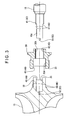
- slippage suppressing means 43, 46, 49 for suppressing slippage in the rotating direction are provided in the connecting portions between the compressor impeller 13, the drive shaft 15, and the sleeve 30.
- Fig. 4 is a front view of the drive shaft 15
- Fig. 5 is a front view of the sleeve 30
- Fig. 6 is a front view of the compressor impeller 13.
- a male screw portion 41 is provided on the portion of the drive shaft 15 to which the sleeve 30 is to be mounted; provided in the sleeve 30 is a female screw portion 42 to be threadedly engaged with the male screw portion 41; through threaded engagement of these portions, the sleeve 30 is mounted to the drive shaft 15, and is prevented from slipping or idling around the drive shaft 15. That is, the screw portions 41 and 42 constitute the first slippage suppressing means 43 of the present invention.
- width across flat portions are formed by a pair of parallel flat surfaces 44 at the proximal end of the outer peripheral portion of the projected portion 19, and as shown in Fig. 5, in the cylindrical portion 33 of the sleeve 30, there is formed a lock groove 45 to be locked to the flat surfaces 44.
- the lock groove 45 is locked to the flat surfaces 44, and slippage in the rotating direction is suppressed between the cylindrical portion 33 and the projected portion 19. That is, a second slippage suppressing means 46 according to the present invention is formed by the flat surfaces 44 and the lock groove 45.
- width across flat portions are formed by a pair of parallel flat surfaces 47 also at the proximal end of the fit-engagement shaft portion 15A, and as shown in Fig. 6, a lock groove 48 to be locked to the flat surfaces 47 is provided in the projected portion 19 of the compressor impeller 13.
- the lock groove 48 is locked to the flat surfaces 47, thereby suppressing slippage in the rotating direction between the drive shaft 15 and the projected portion 19. That is, a third slippage suppressing means 49 according to the present invention is formed by the flat surfaces 47 and the lock groove 48.
- an engagement member 51 protruding toward the forward end, and the engagement member 51 enters an engagement hole 52 provided in the depth portion of the coupling hole 20 of the projected portion 19, and is engaged therewith. Also through the engagement between the engagement member 51 and the engagement hole 52, slippage in the rotating direction is suppressed between the drive shaft 15 and the projected portion 19, so that the engagement member 51 and the engagement hole 52 constitute a third slippage suppressing means 53 according to the present invention.
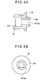
- Figs. 7A, 7B, 8A, and 8B show, as the third embodiment of the present invention, still another modification of the drive shaft 15 and the sleeve 30. While the first slippage suppressing means 43 of the second embodiment is formed by the male screw portion 41 of the drive shaft 15 and the female screw portion 42 of the sleeve 30, in this embodiment, a first slippage suppressing means 56 is formed by a width across flat structure.
- width across flat portions are formed by a pair of parallel flat surfaces 54, and at the outer opening portion of the insertion hole 30A of the sleeve 30 shown in Figs. 8A and 8B, there is provided a lock groove 55 to be locked to the flat surfaces 54.
- the lock groove 55 is locked to the flat surfaces 54, and slippage in the rotating direction is suppressed between the drive shaft 15 and the sleeve 30. That is, the first slippage suppressing means 56 is formed by the flat surfaces 54 and the lock groove 55. Otherwise, this embodiment is substantially of the same configuration as the second embodiment.
- the present invention is not restricted to the above-mentioned embodiments but includes other constructions, etc. allowing achievement of the object of the present invention; for example, the following modifications are to be covered by the scope of the present invention.
- the first through third slippage suppressing means 43, 46, 49, 53, 56 it is also possible to omit the second slippage suppressing means 46 since no slippage will naturally occur between the compressor 13 and the sleeve 30 if the third slippage suppressing means 49 and 53 are provided on the drive shaft 15 and the compressor impeller 13.
- cylindrical portion 33 is provided integrally on the sleeve 30, it is also possible for the cylindrical portion 33 to be provided separately from the sleeve 30 as an annular cylindrical member. Also in the case in which a separate cylindrical member is adopted, the material of the cylindrical member has a coefficient of linear expansion smaller than that of the compressor impeller 13, and is fit-engaged with the projected portion 19.
- turbocharger to be mounted in a gasoline engine or a diesel engine
- present invention is also applicable to other turbo machines equipped with a compressor impeller and a drive shaft for driving the same, such as a turbo compressor, a turbo jet, a turbo blower, and a turbo refrigerator.
Landscapes
- Engineering & Computer Science (AREA)
- Mechanical Engineering (AREA)
- General Engineering & Computer Science (AREA)
- Structures Of Non-Positive Displacement Pumps (AREA)
Abstract
A turbocharger as a turbo machine includes: a compressor impeller (13) having a projected portion (19) at a center of a rear surface; a drive shaft (15) connected to a bottomed coupling hole (20) provided in the projected portion (19) of the compressor impeller (13) through interference fit only; and a sleeve (30) with a cylindrical portion (33) connected to the outer peripheral portion of the projected portion (19) of the compressor impeller (13) by fitting only. The sleeve (30) is formed of a material whose coefficient of linear expansion is smaller than that of the compressor impeller (13). Accordingly, even when the coupling hole (20) in the projected portion (19) undergoes thermal expansion and the diameter of the coupling hole (20) increases, a connection between the drive shaft (15) and the coupling hole (20) can be prevented from being loosened since the radial increase thereof is suppressed by the cylindrical portion (33). Thus, the state of the connection thereof can be well maintained.
Description
- The present invention relates to a turbo machine, a compressor impeller used for the turbo machine, and a method of manufacturing the turbo machine.
- Conventionally, the compressor impeller of a turbo machine such as a turbocharger, is fixed to a drive shaft provided integrally with a turbine by means of a nut. That is, the compressor impeller has an axially extending through-hole, into which the drive shaft is inserted, and the nut is threadedly engaged with a screw portion provided on the distal end portion of the drive shaft, and fastened for fixation.
However, in such a connection structure, in which the compressor impeller is provided with a through-hole, high stress is liable to be generated at some midpoint in the axial direction thereof, and there is a limit to an improvement in terms of durability. - In view of this, there has been proposed a connection structure in which the compressor impeller is provided with, in stead of a through-hole, a bottomed screw hole (blind hole) extending in the axial direction, and in which the drive shaft is threadedly engaged with this screw hole (See, for example, Patent Document 1 and Patent Document 2). Further, in Patent Document 1 and Patent Document 2, there is provided a fit-engagement portion realized through interference fit of the drive shaft with the hole in order to eliminate back-lash in the threaded-engagement portion and to achieve an improvement in terms of concentricity.
In this connection structure, it is only necessary for the screw hole to be long enough to ensure reliable threaded engagement of the drive shaft, and there is no need for it to extend to a midpoint in the axial direction, so that generation of high stress is not easily involved. -
- [Patent Document 1] 05-504178 A
- [Patent Document 2]
US 5,193,989 - However, in the turbocharger as disclosed in Patent Document 1 and Patent Document 2, in effecting the connection, the drive shaft is first threadedly engaged with the screw hole on the compressor impeller side, and mutual fit-engagement is effected in the course of threaded engagement, so that the connection in the threaded-engagement portion, where concentricity is hard to attain, affects the fit-engagement portion, with the result that an accurate concentricity, which ought to be attained by the fit-engagement portion, cannot be achieved. As a result, various problems are involved; for example, the productivity of the turbocharger is impaired, and the drive shaft is deflected to suffer deformation, with the result that an unbalanced state is liable to arise during rotation, making it impossible to achieve an improvement in terms of durability as desired.
- It is an object of the present invention to provide a turbo machine capable of maintaining a satisfactory connection between the compressor impeller and the drive shaft, a compressor impeller to be used in the turbo machine, and a method of manufacturing the turbo machine.
- A turbo machine according to a first invention includes: a compressor impeller having a projected portion at a center of a rear surface; a drive shaft fit-engaged with a bottomed coupling hole provided in the projected portion of the compressor impeller; and a cylindrical member fitted onto an outer peripheral portion of the projected portion corresponding to a fit-engaged portion of the drive shaft concentrically with the drive shaft.
- A turbo machine according to a second invention is characterized in that: in the turbo machine according to the first invention, the fit-engagement of the bottomed coupling hole of the projected portion and the drive shaft is effected through interference fit as defined in JIS B 0401; and the fit-engagement of the projected portion and the cylindrical member is effected through transition fit or clearance fit as defined in JIS B 0401.
Here, the interference fit can be realized by fit-engaging a bottomed hole with a shaft whose diameter is larger than the hole diameter by approximately 10% by press-fitting, forcible press-fitting, shrinkage fit, expansion fit, etc.
The transition fit can be realized by fit-engaging the cylindrical member with the projected portion by slide fit, forcing-in, driving fit, etc.
More specifically, it is possible to adopt, as appropriate, interference fit, transition fit, or clearance fit by selecting the shaft diameter tolerance range class as shown in Table 1 when the hole diameter is 6 mm to 10 mm. -
(Table 1) Reference Hole Shaft Diameter Tolerance Range Transition Fit Clearance Fit Interference Fit H6 g5 h5 js5 k5 m5 f6 g6 h6 js6 k6 m6 n6 p6 H7 f6 g6 h6 js6 k6 m6 n6 p6 r6 s6 t6 u6 x6 e7 f7 h7 js7 H8 f7 h7 e8 f8 h8 d9 e9 H9 d8 e8 c9 d9 e9 H10 b9 c9 d9 - A turbo machine according to a third invention is characterized in that: in the turbo machine according to the first or second invention, the cylindrical member is formed of a material whose coefficient of linear expansion is smaller than that of the compressor impeller.
Here, as the material of the compressor impeller, it is possible to adopt, for example, aluminum (coefficient of linear expansion: 23.9 x 10-61/C°) and duralumin (coefficient of linear expansion: 27.3 x 10-61/C°).
As the material of the cylindrical member, it is possible to adopt, for example, carbon steel (coefficient of linear expansion: 10.1 to 12.1 x 10-61/C°), chromium steel (coefficient of linear expansion: 9.5 to 11.3 x 10-61/C°), nickel steel (coefficient of linear expansion: 18.0 x 10-61/C°), etc. - A turbo machine according to a fourth invention is characterized in that: in the turbo machine according to any one of the first through the third inventions, the drive shaft is provided with a step-like shoulder portion; and a sleeve fitted onto the drive shaft is held between the shoulder portion and the compressor impeller.
- A turbo machine according to a fifth invention is characterized in that: in the turbo machine according to the fourth invention, the sleeve is held between the shoulder portion of the drive shaft and the compressor impeller while bearing axial contact pressure.
- A turbo machine according to a sixth invention is characterized in that: in the turbo machine according to the fourth or fifth invention, the cylindrical member is integrally provided on the sleeve.
- A turbo compressor according to a seventh invention is characterized in that the turbo machine according to any one of the fourth through the sixth inventions further includes: a housing rotatably supporting the drive shaft; a thrust collar fixed to the drive shaft; and a thrust bearing held between the thrust collar and the sleeve and fixed to the housing.
- A turbo machine according to an eighth invention is characterized in that: in the turbo machine according to the seventh invention, the sleeve is equipped with a seal means effecting sealing on lubricating oil and high pressure air between the sleeve and a housing.
- A turbo machine according to a ninth invention is characterized in that: in the turbo machine according to any one of the fourth through the eighth inventions, the sleeve and the drive shaft are provided with a first slippage suppressing means suppressing slippage in a rotating direction through mutual engagement.
- A turbo machine according to a tenth invention is characterized in that: in the turbo machine according to any one of the first through the ninth inventions, the annular member and the compressor impeller are provided with a second slippage suppressing means suppressing slippage in a rotating direction through mutual engagement.
- A turbo machine according to an eleventh invention is characterized in that: in the turbo machine according to any one of the first through the tenth inventions, the compressor impeller and the drive shaft are provided with a third slippage suppressing means suppressing slippage in a rotating direction through mutual engagement.
A turbo machine according to a twelfth invention is characterized in that, in the turbo machine according to any one of the first through the eleventh inventions, the compressor impeller is equipped with an attachment/detachment means facilitating cancellation the fit-engagement of the drive shaft and the bottomed hole and the fit-engagement of the outer peripheral portion of the projected portion and the cylindrical member.
Here, it is desirable for the attachment/detachment means to be provided along the drive shaft connected to the compressor impeller and on the side opposite to the projected portion of the compressor impeller; for example, the attachment/detachment means may be formed by a female screw hole, a male screw, and a boss. - A compressor impeller according to a thirteenth invention for use in a turbo machine includes a cylindrical projected portion projected from a central portion of a rear surface, characterized in that an inner peripheral portion and an outer peripheral portion of the projected portion respectively constitute a first connecting portion and a second connecting portion for incorporation into the turbo machine.
- According to a fourteenth invention, there is provided a method of manufacturing a turbo machine which includes: a compressor impeller having a projected portion at a center of a rear surface; a drive shaft fit-engaged with a bottomed coupling hole provided in the projected portion of the compressor impeller; a housing rotatably supporting the drive shaft; and a cylindrical member fitted onto an outer peripheral portion of the projected portion corresponding to the fit-engaged portion of the drive shaft concentrically with the drive shaft. The method includes the steps of: inserting the drive shaft into the housing to cause a distal end of the drive shaft to be exposed through the housing; fitting the cylindrical member onto the drive shaft; and press-fitting the distal end of the drive shaft into the coupling hole of the compressor impeller and press-fitting the cylindrical member onto the projected portion.
- According to the first invention as described above, the drive shaft is fit-engaged with the projected portion of the compressor impeller; the cylindrical member is fit-engaged with the outer periphery of this projected portion, so that even when the drive shaft and the compressor impeller attain high temperature as a result of the driving of the turbo machine, and the compressor impeller expands and the fit-engagement of the drive shaft is loosened, the fit-engagement of the cylindrical member on the outer peripheral side is enhanced, thus preventing the drive shaft from being easily detached from the projected portion of the compressor impeller and making it possible to reliably attain an improvement in terms of durability.
- According to the second invention, the fit-engagement of the bottomed coupling hole of the projected portion and the drive shaft is effected through interference fit, and the fit-engagement of the projected portion and the cylindrical member is effected through transition fit or clearance fit, so that, even when press-fitting, etc. of the drive shaft into the bottomed coupling hole is effected to expand the outer periphery of the projected portion, it is possible to reliably fit-engage the cylindrical member with the outer periphery of the projected portion since the fit-engagement between the projected portion and cylindrical member is loosened.
According to the third invention, the cylindrical member is formed of a material whose coefficient of linear expansion is smaller than that of the compressor impeller, whereby, even if the compressor impeller attains high temperature and expands, the fit-engagement in the outer periphery is further tightened since the expansion of the cylindrical member as a result of the increase in temperature is smaller than that of the compressor impeller, making it possible to maintain a firm fit-engagement between the drive shaft and the compressor impeller. - According to the fourth invention, it is possible to arrange the compressor impeller, the sleeve, etc. at appropriate axial positions on the drive shaft.
According to the fifth invention, the sleeve is held between the compressor impeller and the shoulder portion while bearing a contact pressure, so that it is possible to rotate the sleeve reliably together with the drive shaft. - According to the sixth invention, the cylindrical member is provided integrally with the sleeve, so that it is possible to reduce the number of components and assemblage man-hours.
- According to the seventh invention, the thrust bearing is held between the sleeve and the thrust collar, so that it is possible to reliably prevent the drive shaft from being axially deviated through the sleeve and the thrust collar. Further, due to the construction in which the thrust bearing is held between two components, unlike the construction in which a peripheral groove is provided in the sleeve and in which a horse-shoe-shaped thrust bearing is arranged in this groove, it is possible to use an annular thrust bearing, making it possible to support the rotating surface over the entire periphery in a well-balanced manner.
- According to the eighth embodiment, the sleeve is provided with a seal means for sealing up lubricating oil and high pressure air, so that there is no fear of the high pressure supply air on the compressor impeller side entering the lubricated portion of the drive shaft and leaking therethrough, or the lubricating oil in the lubricated portion leaking out to the supercharged air side to get mixed therein.
According the ninth invention, the sleeve and the drive shaft are provided with the first slippage suppressing means, so that it is possible to integrally rotate the sleeve and the drive shaft, making it possible to prevent seizure or the like from occurring therebetween. - According to the tenth and eleventh inventions, the cylindrical member and the compressor impeller are provided with the second slippage suppressing means, and the compressor impeller and the drive shaft are provided with the third slippage suppressing means, so that, as compared with the case in which the connection is effected through mutual fitting only, the burden on the connection surfaces can be mitigated, making it possible to reliably cope with slippage.
According to the twelfth invention, the compressor impeller is provided with the attachment/detachment means, whereby it is possible to easily cancel the fit-engagement between the compressor impeller and the drive shaft by using the attachment/detachment means, so that it is possible to perform repair easily at the time of failure. - According to the thirteenth invention, the compressor impeller is incorporated into the turbo machine by utilizing the connecting portions of both the outer peripheral portion and the inner peripheral portion of the projected portion, so that, as compared with the prior-art technique, in which the connection is effected by utilizing the inner peripheral portion, it is possible to enhance the connection strength, making it possible to achieve an improvement in terms of durability.
According to the fourteenth invention, it is possible to fit the cylindrical member onto the drive shaft after the insertion of the drive shaft into the housing, and to sequentially effect the press-fitting thereof into the coupling hole of the compressor impeller and the press-fitting of the cylindrical member onto the projected portion, so that the assembly operation is easy to perform, and it is possible to shorten the requisite time for incorporation. -
- Fig. 1 is a sectional view of a turbo machine according to a first embodiment of the present invention;
- Fig. 2 is a sectional view of a main portion of the turbo machine;
- Fig. 3 is a sectional view of a connecting portion according to a second embodiment of the present invention;
- Fig. 4 is a front view of a drive shaft according to the embodiment;
- Fig. 5 is a front view of a sleeve according to the embodiment;
- Fig. 6 is a front view of a compressor impeller according to the embodiment;
- Fig. 7A is a sectional view, taken along the line A-A of Fig. 7B, of a connecting portion according to a third embodiment of the present invention;
- Fig. 7B is a side view of a drive shaft according to the embodiment;
- Fig. 8A is a side sectional view of a sleeve according to the embodiment; and
- Fig. 8B is a rear view of the sleeve of the embodiment.
- 1 ... turbocharger (turbo machine), 13 ... compressor impeller, 15 ... drive shaft, 16 ... housing (non-rotating member), 18 ... shoulder portion, 19 ... projected portion, 19A ... second connecting portion, 20 ... coupling hole, 20A ... first connecting portion, 30 ... sleeve, 31 ... thrust collar, 32 ... thrust bearing, 33 ... cylindrical portion (cylindrical member), 34 ... seal ring (seal means), 43, 56 ... first slippage suppressing means, 46 ... second slippage suppressing means, 49, 53 ... third slippage suppressing means
- In the following, embodiments of the present invention will be described with reference to the drawings. From the second embodiment onward, described below, the members that are the same as those of the first embodiment described below are indicated by the same reference symbols, and a detailed description thereof will be omitted or simplified from the second embodiment onward.
- Fig. 1 is a sectional view of a turbocharger (turbo machine) 1 according to the first embodiment of the present invention, and Fig. 2 is a sectional view of a main portion of the turbocharger 1.
- As shown in Fig. 1, the turbocharger 1, which is to be mounted, for example, in a gasoline engine or a diesel engine, is equipped with a
compressor 11 connected to a midpoint of an intake pipe leading to an engine (not shown), and anexhaust turbine 12 connected to a midpoint of an exhaust pipe.
Thecompressor 11 has acompressor impeller 13 for compressing intake air from the outside through rotation.
Although not shown, thecompressor impeller 13 has a hub substantially circular in front view and a plurality of vanes mounted thereto so as to be arranged in the rotating direction of the hub, and is formed of aluminum alloy casting. Substantially the central portion of thecompressor impeller 13 protrudes in a chevron-like fashion, and at the flat forward end thereof, there is formed afemale screw hole 131 as an attachment/detachment means. After thecompressor impeller 13 has been fit-engaged with adrive shaft 15 by manufacturing procedures described below, thefemale screw hole 131 is used when they are to be separated from each other again. In this embodiment, it is provided in order to facilitate the separation, which is effected by threadedly engaging a removing tool (not shown) with thefemale screw 131 and pulling the removing tool. - The
exhaust turbine 12 has aturbine wheel 14, which is rotated by exhaust gas that flows in; theturbine wheel 14 is formed integrally with thesteel drive shaft 15 by friction welding, TIG welding, MIG welding or the like. Thedrive shaft 15 is rotatably supported by a full float bearing 17 provided in ahousing 16, with thecompressor impeller 13 being connected to the distal end of thedrive shaft 15. - In the following, with reference to Fig. 2, the connecting portion between the
compressor impeller 13 and thedrive shaft 15 will be described in detail.
At the center of the rear side of thecompressor impeller 13, that is, at the center of the side thereof opposed to theturbine wheel 14, there is provided a projectedportion 19 projected toward theturbine wheel 14 side. In the projectedportion 19, there is provided acoupling hole 20 extending axially toward the depth side thereof.
Thedrive shaft 15 is to be inserted into thecoupling hole 20 for connection; unlike the conventional coupling hole, which is a through-hole extending through thecompressor impeller 13, thecoupling hole 20 is a bottomed hole. The inner peripheral portion of thecoupling hole 20 constitutes a first connectingportion 20A to be connected with thedrive shaft 15. - At the distal end of the
drive shaft 15, there is provided a fit-engagement shaft portion 15A to be inserted into thecoupling hole 20 of thecompressor impeller 13 and fit-engaged with the first connectingportion 20A thereof; on the proximal end side with respect to the fit-engagement shaft portion 15A, there is provided aninsert portion 15B onto which asleeve 30 is to be fitted. - The fit-engagement between the fit-
engagement shaft portion 15A and the first connectingportion 20A is effected through interference fit on a hole basis (e.g., H6/u6 in terms of JIS fit symbol). No other fixation structure such as a conventional one using a screw is adopted; the connection is effected solely through fit-engagement between thecompressor impeller 13 and thedrive shaft 15. - The
sleeve 30 is formed of a substantially cylindrical member that is open on thecompressor impeller 13 side; it is formed of steel, whose coefficient of linear expansion is smaller than that of thecompressor impeller 13, which is formed of aluminum.
Thesleeve 30 is equipped with aninsertion hole 30A into which thedrive shaft 15 is to be inserted; on thecompressor impeller 13 side with respect to theinsertion hole 30A, there is integrally provided a cylindrical portion (cylindrical member) 33 having a fit-engagement hole portion 33A communicating with theinsertion hole 30A.
The fit-engagement hole portion 33A of thecylindrical portion 33 is of a diameter larger than theinsertion hole 30A; the projectedportion 19 of thecompressor impeller 13 is inserted thereinto for fit-engagement. That is, the outer peripheral portion of the projectedportion 19 to be inserted constitutes a second connectingportion 19A to be connected with the fit-engagement hole portion 33A. - The fit-engagement between the fit-
engagement hole portion 33A and the second connectingportion 19A is effected through clearance fit or transition fit on a hole basis (e.g., H6/h6, H6/k6 in terms of JIS fit symbol); the fit-engagement between the fit-engagement shaft portion 15A and the first connectingportion 20A is set tighter than that.
As a result, the concentricity between thedrive shaft 15 and thecompressor impeller 13 is reliably secured without being affected by the fit-engagement between the fit-engagement hole portion 33A and the second connectingportion 19A. Here also, there is no fixation structure such as one using a screw is adopted, and the connection between thecompressor impeller 13 and the cylindrical portion 33 (sleeve 30) is effected solely through fit-engagement. - In this way, the second connecting
portion 19A of the projectedportion 19 is fit-engaged with thecylindrical portion 33 whose coefficient of linear expansion is smaller than that of thecompressor impeller 13, so that, even when thedrive shaft 15 and thecompressor impeller 13 attain high temperature, and thecompressor impeller 13 side portion undergoes thermal expansion and the diameter of thecoupling hole 20 tends to increase, it is possible to suppress the expansion by thecylindrical portion 33, enabling to prevent thedrive shaft 15 from becoming subject to detachment from thecoupling hole 20 of the projectedportion 19 and to reliably achieve an improvement in terms of durability. - Further, instead of a through-hole, the bottomed
coupling hole 20 is provided on thecompressor impeller 13 side, so that high stress is not easily generated in the inner central portion of thecompressor impeller 13, making it possible to achieve a substantial improvement in terms of durability.
Further, thedrive shaft 15 and thecompressor impeller 13 are not connected together through threaded engagement but are connected together solely by fit-engagement through interference fit between the first connectingportion 20A and the fit-engagement shaft portion 15A, so that the assembly can be conducted with high precision due to the concentricity of the fit-engagement portion; further, unlike the conventional threaded-engagement connection structure, it involves no deformation of thedrive shaft 15, galling of the thread portions, etc., thus providing a satisfactory assembly property. - Further, through the fit-engagement between the
compressor impeller 13 and thedrive shaft 15, thesleeve 30 is pressed against a step-like shoulder portion 18 provided on thedrive shaft 15, and is held between thecompressor impeller 13 and theshoulder portion 18 under an axial contact pressure. Thus, although thesleeve 30 is not connected with thedrive shaft 15, it is held under a contact pressure, whereby thecompressor impeller 13 and thesleeve 30 are arranged at appropriate axial positions on thedrive shaft 15, and thesleeve 30 rotates integrally with thedrive shaft 15.
Between thesleeve 30 and theshoulder portion 18, there is arranged athrust collar 31, which is also held under a contact pressure, and is fixed to thedrive shaft 15 to rotate integrally therewith. - Further, on the outer peripheral side of an
abutment portion 30B of thesleeve 30 abutting thethrust collar 31, there is arranged athrust bearing 32 so as to be held between thesleeve 30 and thethrust collar 31. Thethrust bearing 32 is formed as an annular member allowing insertion of theabutment portion 30B, and is fixed in position within a recessedspace 16A provided in thehousing 16. Unlike a horse-shoe-shaped thrust bearing, the annular thrust bearing 32 can support the rotating surfaces of thesleeve 30 and thethrust collar 31 over the entire periphery in a well-balanced manner. - The
sleeve 30 is arranged so as to be accommodated within the recessedspace 16A of thehousing 16, with the above-mentionedcylindrical portion 33 slightly protruding from the recessedspace 16A toward thecompressor impeller 13 side. In the outer periphery of the proximal end portion of thecylindrical portion 33, there is formed a recessed groove over the entire periphery thereof, and a pair of seal rings (seal means) 34 are fitted in the recessed groove so as to be axially arranged side by side. - The seal rings 34 are held in contact with a retaining
ring 35 arranged within the recessedspace 16A so as to cover thethrust bearing 32, effecting sealing between the interior and the exterior of the recessedspace 16A. That is, due to the seal rings 34, there is no fear of the lubricating oil supplied to thethrust bearing 32 leaking from the recessedspace 16A side to thecompressor impeller 13 side or the high pressure supply air generated on thecompressor impeller 13 side leaking through the lubricated portion in the recessedspace 16A. On the outer side of the retainingring 35, there is provided alock ring 36, which prevents the retainingring 35 from being detached from the recessedspace 16A. - When manufacturing the turbocharger 1, the full float bearing 17 is first arranged in the
housing 16, and thedrive shaft 15, which is integrated with theturbine wheel 14, is inserted into the full float bearing 17 from theexhaust turbine 12 side.
After that, thethrust collar 31 is fitted onto thedrive shaft 15 protruding from the recessedspace 16A of thehousing 16, and thethrust bearing 32, the retainingring 35, and thelock ring 36 are successively arranged within the recessedspace 16A, and further, thesleeve 30 is fitted onto thedrive shaft 15.
Since thecylindrical portion 33 is integrally provided on thesleeve 30, there is no need to incorporate thecylindrical portion 33 as a separate component.
Then, the fit-engagement shaft portion 15A of thedrive shaft 15 is press-fitted into thecoupling hole 20, and thecylindrical portion 33 is press-fitted onto the outer peripheral surface of the projectedportion 19 for fit-engagement. By the above-mentioned procedures, the incorporation of thecompressor impeller 13 into the turbocharger 1 is completed. - Next, the second embodiment of the present invention will be described.
In the first embodiment described above, the distal end portion of thedrive shaft 15 has a columnar configuration, and is press-fitted into the circular bottomedhole 20 for fit-engagement; further, thecylindrical portion 33 is fixed to the columnar projectedportion 19 for fit-engagement.
In contrast, in the second embodiment of the present invention, as shown in Fig. 3,slippage suppressing means compressor impeller 13, thedrive shaft 15, and thesleeve 30. Fig. 4 is a front view of thedrive shaft 15, Fig. 5 is a front view of thesleeve 30, and Fig. 6 is a front view of thecompressor impeller 13. - As shown in Fig. 3, a
male screw portion 41 is provided on the portion of thedrive shaft 15 to which thesleeve 30 is to be mounted; provided in thesleeve 30 is afemale screw portion 42 to be threadedly engaged with themale screw portion 41; through threaded engagement of these portions, thesleeve 30 is mounted to thedrive shaft 15, and is prevented from slipping or idling around thedrive shaft 15. That is, thescrew portions slippage suppressing means 43 of the present invention. - As shown in Fig. 6, in the
compressor impeller 13, width across flat portions are formed by a pair of parallelflat surfaces 44 at the proximal end of the outer peripheral portion of the projectedportion 19, and as shown in Fig. 5, in thecylindrical portion 33 of thesleeve 30, there is formed alock groove 45 to be locked to the flat surfaces 44. In the state in which the projectedportion 19 and thesleeve 30 are fit-engaged with each other, thelock groove 45 is locked to theflat surfaces 44, and slippage in the rotating direction is suppressed between thecylindrical portion 33 and the projectedportion 19. That is, a secondslippage suppressing means 46 according to the present invention is formed by theflat surfaces 44 and thelock groove 45. - Further, as shown in Fig. 4, in the
drive shaft 15, width across flat portions are formed by a pair of parallelflat surfaces 47 also at the proximal end of the fit-engagement shaft portion 15A, and as shown in Fig. 6, alock groove 48 to be locked to theflat surfaces 47 is provided in the projectedportion 19 of thecompressor impeller 13. In the state in which thedrive shaft 15 and the projectedportion 19 are fit-engaged with each other, thelock groove 48 is locked to theflat surfaces 47, thereby suppressing slippage in the rotating direction between thedrive shaft 15 and the projectedportion 19. That is, a thirdslippage suppressing means 49 according to the present invention is formed by theflat surfaces 47 and thelock groove 48. - In addition, at the distal end of the
drive shaft 15, there is provided anengagement member 51 protruding toward the forward end, and theengagement member 51 enters anengagement hole 52 provided in the depth portion of thecoupling hole 20 of the projectedportion 19, and is engaged therewith. Also through the engagement between theengagement member 51 and theengagement hole 52, slippage in the rotating direction is suppressed between thedrive shaft 15 and the projectedportion 19, so that theengagement member 51 and theengagement hole 52 constitute a thirdslippage suppressing means 53 according to the present invention. - Figs. 7A, 7B, 8A, and 8B show, as the third embodiment of the present invention, still another modification of the
drive shaft 15 and thesleeve 30. While the firstslippage suppressing means 43 of the second embodiment is formed by themale screw portion 41 of thedrive shaft 15 and thefemale screw portion 42 of thesleeve 30, in this embodiment, a firstslippage suppressing means 56 is formed by a width across flat structure. - More specifically, as shown in Figs. 7A and 7B, at the proximal end of the
insertion portion 15B of the drive shaft 15 (the portion into which thesleeve 30 is inserted), width across flat portions are formed by a pair of parallelflat surfaces 54, and at the outer opening portion of theinsertion hole 30A of thesleeve 30 shown in Figs. 8A and 8B, there is provided alock groove 55 to be locked to the flat surfaces 54. In the state in which thesleeve 30 is fitted onto thedrive shaft 15, thelock groove 55 is locked to theflat surfaces 54, and slippage in the rotating direction is suppressed between thedrive shaft 15 and thesleeve 30. That is, the firstslippage suppressing means 56 is formed by theflat surfaces 54 and thelock groove 55. Otherwise, this embodiment is substantially of the same configuration as the second embodiment. - The present invention is not restricted to the above-mentioned embodiments but includes other constructions, etc. allowing achievement of the object of the present invention; for example, the following modifications are to be covered by the scope of the present invention.
For example, while in the second and third embodiments there are provided the first through thirdslippage suppressing means slippage suppressing means 46 since no slippage will naturally occur between thecompressor 13 and thesleeve 30 if the thirdslippage suppressing means drive shaft 15 and thecompressor impeller 13. - While in the above-mentioned embodiments the
cylindrical portion 33 is provided integrally on thesleeve 30, it is also possible for thecylindrical portion 33 to be provided separately from thesleeve 30 as an annular cylindrical member. Also in the case in which a separate cylindrical member is adopted, the material of the cylindrical member has a coefficient of linear expansion smaller than that of thecompressor impeller 13, and is fit-engaged with the projectedportion 19. - The most preferable constructions and method for carrying out the present invention disclosed by the above description should not be construed restrictively. That is, while the present invention has been depicted and illustrated mainly with reference to specific embodiments, it is possible for those skilled in the art to make various modifications of the above embodiments in terms of configuration, amount, and other details without departing from the scope of technical idea and object of the present invention.
Thus, the configurations, amounts, etc. in the above-mentioned embodiments are only given by way of example to facilitate the understanding of the present invention, and restrict in no way the present invention, so that any description in which the components are referred to with some or none of the above-mentioned restrictions in terms of configuration, amount, etc. is to be covered by the scope of the present invention. - Apart from a turbocharger to be mounted in a gasoline engine or a diesel engine, the present invention is also applicable to other turbo machines equipped with a compressor impeller and a drive shaft for driving the same, such as a turbo compressor, a turbo jet, a turbo blower, and a turbo refrigerator.
Claims (14)
- A turbo machine, comprising:a compressor impeller having a projected portion at a center of a rear surface;a drive shaft fit-engaged with a bottomed coupling hole provided in the projected portion of the compressor impeller; anda cylindrical member fitted onto an outer peripheral portion of the projected portion corresponding to a fit-engaged portion of the drive shaft concentrically with the drive shaft.
- The turbo machine according to Claim 1, wherein
the fit-engagement of the bottomed coupling hole of the projected portion and the drive shaft is effected through interference fit as defined in JIS B 0401; and
the fit-engagement of the projected portion and the cylindrical member is effected through transition fit or clearance fit as defined in JIS B 0401. - The turbo machine according to Claim 1 or Claim 2, wherein
the cylindrical member is formed of a material whose coefficient of linear expansion is smaller than that of the compressor impeller. - The turbo machine according to any one of Claims 1 through 3, wherein
the drive shaft is provided with a step-like shoulder portion; and
a sleeve fitted onto the drive shaft is held between the shoulder portion and the compressor impeller. - The turbo machine according to Claim 4, wherein
the sleeve is held between the shoulder portion of the drive shaft and the compressor impeller while bearing axial contact pressure. - The turbo machine according to Claim 4 or Claim 5, wherein
the cylindrical member is integrally provided on the sleeve. - The turbo machine according to any one of Claims 4 through 6, further comprising:a housing rotatably supporting the drive shaft;a thrust collar fixed to the drive shaft; anda thrust bearing held between the thrust collar and the sleeve and fixed to the housing.
- The turbo machine according to Claim 7, wherein
the sleeve is equipped with a seal means effecting sealing on lubricating oil and high pressure air between the sleeve and a housing. - The turbo machine according to any one of Claims 4 through 8, wherein
the sleeve and the drive shaft are provided with a first slippage suppressing means suppressing slippage in a rotating direction through mutual engagement. - The turbo machine according to any one of Claims 1 through 9, wherein
the annular member and the compressor impeller are provided with a second slippage suppressing means suppressing slippage in a rotating direction through mutual engagement. - The turbo machine according to any one of Claims 1 through 10, wherein
the compressor impeller and the drive shaft are provided with a third slippage suppressing means suppressing slippage in a rotating direction through mutual engagement. - The turbo machine according to any one of Claims 1 through 11, wherein
the compressor impeller is equipped with an attachment and detachment means facilitating cancellation the fit-engagement of the drive shaft and the bottomed hole and the fit-engagement of the outer peripheral portion of the projected portion and the cylindrical member. - A compressor impeller for use in a turbo machine, comprising:a cylindrical projected portion projected from a central portion of a rear surface,wherein an inner peripheral portion and an outer peripheral portion of the projected portion respectively constitute a first connecting portion and a second connecting portion for incorporation into the turbo machine.
- A method of manufacturing a turbo machine which includes:a compressor impeller having a projected portion at a center of a rear surface;a drive shaft fit-engaged with a bottomed coupling hole provided in the projected portion of the compressor impeller;a housing rotatably supporting the drive shaft; anda cylindrical member fitted onto an outer peripheral portion of the projected portion corresponding to the fit-engaged portion of the drive shaft concentrically with the drive shaft,the method comprising the steps of:inserting the drive shaft into the housing to cause a distal end of the drive shaft to be exposed through the housing;fitting the cylindrical member onto the drive shaft; andpress-fitting the distal end of the drive shaft into the coupling hole of the compressor impeller and press-fitting the cylindrical member onto the projected portion.
Applications Claiming Priority (2)
| Application Number | Priority Date | Filing Date | Title |
|---|---|---|---|
| JP2004304473 | 2004-10-19 | ||
| PCT/JP2005/019126 WO2006043556A1 (en) | 2004-10-19 | 2005-10-18 | Turbo machine, compressor impeller used for turbo machine, and method of manufacturing turbo machine |
Publications (1)
| Publication Number | Publication Date |
|---|---|
| EP1803941A1 true EP1803941A1 (en) | 2007-07-04 |
Family
ID=36202971
Family Applications (1)
| Application Number | Title | Priority Date | Filing Date |
|---|---|---|---|
| EP05795829A Withdrawn EP1803941A1 (en) | 2004-10-19 | 2005-10-18 | Turbo machine, compressor impeller used for turbo machine, and method of manufacturing turbo machine |
Country Status (6)
| Country | Link |
|---|---|
| US (1) | US7909578B2 (en) |
| EP (1) | EP1803941A1 (en) |
| JP (1) | JP4637853B2 (en) |
| KR (1) | KR100861968B1 (en) |
| CN (1) | CN100476214C (en) |
| WO (1) | WO2006043556A1 (en) |
Cited By (6)
| Publication number | Priority date | Publication date | Assignee | Title |
|---|---|---|---|---|
| DE102008056059B4 (en) * | 2008-08-04 | 2010-11-18 | Mtu Friedrichshafen Gmbh | Exhaust gas turbocharger and method for assembling an exhaust gas turbocharger |
| EP2280177A3 (en) * | 2009-07-31 | 2012-01-11 | Bosch Mahle Turbo Systems GmbH & Co. KG | Charging device, in particular exhaust gas turbocharger for a motor vehicle |
| EP2535592A3 (en) * | 2011-06-15 | 2013-05-15 | Honeywell International Inc. | Wheel and replaceable nose piece |
| GB2498361A (en) * | 2012-01-10 | 2013-07-17 | Napier Turbochargers Ltd | Silicon carbide reinforced aluminium alloy turbocharger impeller |
| WO2015000629A1 (en) * | 2013-07-03 | 2015-01-08 | Continental Automotive Gmbh | Rotor for a turbocharger device, turbocharger device having a rotor, and shaft for a rotor of said type |
| US9074477B2 (en) | 2011-12-23 | 2015-07-07 | Napier Turbochargers Limited | Connector |
Families Citing this family (36)
| Publication number | Priority date | Publication date | Assignee | Title |
|---|---|---|---|---|
| ITMI20071100A1 (en) * | 2007-05-30 | 2008-11-30 | Nuovo Pignone Spa | ANCHORAGE SYSTEM FOR THE IMPELLERS OF A ROTARY FLUID MACHINE |
| KR101182122B1 (en) * | 2008-04-08 | 2012-09-13 | 가부시키가이샤 아이에이치아이 | Turbocharger |
| DE102008056058A1 (en) * | 2008-08-04 | 2010-02-11 | Mtu Friedrichshafen Gmbh | Exhaust gas turbo charger, has rotor and compressor rotor coaxially connected via shaft, thread adapter screwed on shaft from side of compressor, and centric recess provided with internal thread fitted at external thread at thread adapter |
| DE102009015862A1 (en) * | 2009-04-01 | 2010-10-07 | Siemens Aktiengesellschaft | Gear compressor rotor for cold gas applications |
| JP4856748B2 (en) * | 2009-10-22 | 2012-01-18 | 本田技研工業株式会社 | Turbocharger |
| DE102009060056A1 (en) * | 2009-12-22 | 2011-06-30 | BorgWarner Inc., Mich. | Wave bond of an exhaust gas turbocharger |
| JP5689607B2 (en) * | 2010-03-17 | 2015-03-25 | 東京電力株式会社 | Axial flow compressor |
| US9217370B2 (en) | 2011-02-18 | 2015-12-22 | Dynamo Micropower Corporation | Fluid flow devices with vertically simple geometry and methods of making the same |
| JP6111260B2 (en) * | 2011-11-23 | 2017-04-05 | ボーグワーナー インコーポレーテッド | Exhaust gas turbocharger |
| WO2013106303A1 (en) * | 2012-01-13 | 2013-07-18 | Borgwarner Inc. | Sealing system and turbocharger incorporating the same |
| IN2014DN09636A (en) * | 2012-04-24 | 2015-07-31 | Borgwarner Inc | |
| RU2014148095A (en) * | 2012-05-16 | 2016-06-27 | Боргварнер Инк. | OIL SEAL FOR OIL BREAKER RING AND TURBOCHARGER CONTAINING SUCH OIL SEAL |
| CN102767398A (en) * | 2012-07-04 | 2012-11-07 | 联优机械(常熟)有限公司 | Impeller and main shaft matched structure of turbo expander |
| GB201220300D0 (en) | 2012-11-12 | 2012-12-26 | Cummins Ltd | Turbomachine bearing assembly preloading arrangement |
| JP6333861B2 (en) | 2013-02-22 | 2018-05-30 | エコモーターズ,インコーポレーテッド | Fitting an electric rotor to a turbomachine shaft |
| JP6232713B2 (en) * | 2013-03-06 | 2017-11-22 | 株式会社島津製作所 | Vacuum pump |
| US20140322019A1 (en) * | 2013-04-30 | 2014-10-30 | Dresser Inc. | Rotary element and compressor device comprised thereof |
| DE112014003073T5 (en) * | 2013-07-26 | 2016-03-17 | Borgwarner Inc., Patent Department | Turbocharger scavenging seal with axially symmetrical supply hollows |
| US9664050B2 (en) | 2013-10-25 | 2017-05-30 | Ecomotors, Inc. | Bearings for a turbomachine having an electric motor |
| CN105683502B (en) * | 2013-12-11 | 2019-01-01 | 三菱重工业株式会社 | Rotary body and method of manufacturing the same |
| US20170074287A1 (en) * | 2014-03-11 | 2017-03-16 | Borgwarner Inc. | Compressor wheel-shaft assembly |
| US10030580B2 (en) | 2014-04-11 | 2018-07-24 | Dynamo Micropower Corporation | Micro gas turbine systems and uses thereof |
| FR3027070B1 (en) * | 2014-10-09 | 2019-08-02 | Cryostar Sas | TURBOMACHINE ROTATING AT HIGH SPEEDS |
| CN107709725A (en) * | 2015-06-11 | 2018-02-16 | 伊顿公司 | Bearing plate for supercharger |
| CN105863740A (en) * | 2016-03-24 | 2016-08-17 | 中国北方发动机研究所(天津) | High-reliability turbocharger turbine rotary shaft interlocking type connecting structure |
| DE102016119233A1 (en) * | 2016-10-10 | 2018-04-12 | Ihi Charging Systems International Gmbh | Tool for an exhaust gas turbocharger and turbocharger |
| DE102017207259A1 (en) * | 2017-04-28 | 2018-10-31 | Continental Automotive Gmbh | Turbocharger for an internal combustion engine, turbocharger rotor and compressor wheel |
| JP7187668B2 (en) * | 2019-03-14 | 2022-12-12 | 三菱重工エンジン&ターボチャージャ株式会社 | Compressor wheel device and turbocharger |
| CN110242354B (en) * | 2019-05-28 | 2024-03-29 | 华电电力科学研究院有限公司 | Improved efficient radial turbine distributed residual pressure power generation system and working method thereof |
| US11401942B2 (en) | 2020-05-15 | 2022-08-02 | Garrett Transportation I Inc | Fastener arrangement for rotating group of turbomachine |
| US11560900B2 (en) * | 2020-06-09 | 2023-01-24 | Emerson Climate Technologies, Inc. | Compressor driveshaft assembly and compressor including same |
| US11719243B2 (en) * | 2021-08-06 | 2023-08-08 | Pratt & Whitney Canada Corp. | Impeller rotor configured with wear resistant seal land |
| US11674406B2 (en) | 2021-08-06 | 2023-06-13 | Pratt & Whitney Canada Corp. | Variable gap between impeller rotor and static structure |
| US12018680B2 (en) * | 2022-04-12 | 2024-06-25 | Phinia Delphi Luxembourg Sarl | Fluid pump with thrust bearing driver |
| US12031543B2 (en) * | 2022-11-16 | 2024-07-09 | Copeland Lp | Foil bearing and driveshaft assemblies and compressor including same |
| US12510082B1 (en) | 2024-11-01 | 2025-12-30 | Pratt & Whitney Canada Corp. | Impeller rotor seal runner with divergent guide surface |
Family Cites Families (22)
| Publication number | Priority date | Publication date | Assignee | Title |
|---|---|---|---|---|
| JPS48100205U (en) * | 1972-02-28 | 1973-11-26 | ||
| GB1430308A (en) | 1973-04-06 | 1976-03-31 | Woollenweber W E | Rotatable assembly |
| US4340317A (en) * | 1981-05-07 | 1982-07-20 | Northern Research & Engineering Corp. | Splineless coupling means |
| JPS6026197A (en) * | 1983-07-21 | 1985-02-09 | Asahi Glass Co Ltd | Turbo machine and blade wheel chip |
| JPS6023220U (en) * | 1983-07-22 | 1985-02-18 | トヨタ自動車株式会社 | Rotor for turbo charger |
| JPS611693U (en) * | 1984-06-11 | 1986-01-08 | 日産自動車株式会社 | compressor impeller |
| JPH0216079Y2 (en) * | 1985-03-19 | 1990-05-01 | ||
| JPS6326701U (en) * | 1986-08-05 | 1988-02-22 | ||
| US4986733A (en) | 1989-10-30 | 1991-01-22 | Allied-Signal, Inc. | Turbocharger compressor wheel assembly with boreless hub compressor wheel |
| JP2815697B2 (en) * | 1990-10-31 | 1998-10-27 | 日本特殊陶業株式会社 | Turbocharger and turbine blade body |
| US5176497A (en) * | 1991-01-22 | 1993-01-05 | Allied-Signal Inc. | Boreless hub compressor wheel assembly for a turbocharger |
| US5193989A (en) | 1991-07-19 | 1993-03-16 | Allied-Signal Inc. | Compressor wheel and shaft assembly for turbocharger |
| JPH0521200U (en) * | 1991-09-02 | 1993-03-19 | 株式会社神戸製鋼所 | Centrifugal compressor rotor |
| US6116855A (en) * | 1998-07-27 | 2000-09-12 | Hypro Corporation | Flexible impeller removal system |
| CN100340742C (en) * | 2000-11-30 | 2007-10-03 | 霍尼韦尔加勒特股份有限公司 | Variable geometry turbocharger with sliding piston |
| JP2003139156A (en) * | 2001-11-05 | 2003-05-14 | Kawasaki Heavy Ind Ltd | Assembly rotating body and its fastening mechanism |
| ES2297188T3 (en) | 2002-05-06 | 2008-05-01 | Abb Turbo Systems Ag | DEVICE FOR FIXING A ROTOR ON A TREE. |
| GB2392477A (en) * | 2002-08-24 | 2004-03-03 | Alstom | Turbocharger |
| JP2004090130A (en) | 2002-08-30 | 2004-03-25 | Mitsubishi Heavy Ind Ltd | JOINING METHOD FOR TiAL-BASE ALLOY AND STEEL PRODUCT |
| GB0224721D0 (en) | 2002-10-24 | 2002-12-04 | Holset Engineering Co | Compressor wheel assembly |
| US6896479B2 (en) * | 2003-04-08 | 2005-05-24 | General Motors Corporation | Turbocharger rotor |
| US7052241B2 (en) * | 2003-08-12 | 2006-05-30 | Borgwarner Inc. | Metal injection molded turbine rotor and metal shaft connection attachment thereto |
-
2005
- 2005-10-18 WO PCT/JP2005/019126 patent/WO2006043556A1/en not_active Ceased
- 2005-10-18 EP EP05795829A patent/EP1803941A1/en not_active Withdrawn
- 2005-10-18 US US11/665,232 patent/US7909578B2/en not_active Expired - Fee Related
- 2005-10-18 CN CNB2005800351736A patent/CN100476214C/en not_active Expired - Fee Related
- 2005-10-18 KR KR1020077008899A patent/KR100861968B1/en not_active Expired - Fee Related
- 2005-10-18 JP JP2006543007A patent/JP4637853B2/en not_active Expired - Fee Related
Non-Patent Citations (1)
| Title |
|---|
| See references of WO2006043556A1 * |
Cited By (8)
| Publication number | Priority date | Publication date | Assignee | Title |
|---|---|---|---|---|
| DE102008056059B4 (en) * | 2008-08-04 | 2010-11-18 | Mtu Friedrichshafen Gmbh | Exhaust gas turbocharger and method for assembling an exhaust gas turbocharger |
| EP2280177A3 (en) * | 2009-07-31 | 2012-01-11 | Bosch Mahle Turbo Systems GmbH & Co. KG | Charging device, in particular exhaust gas turbocharger for a motor vehicle |
| EP2535592A3 (en) * | 2011-06-15 | 2013-05-15 | Honeywell International Inc. | Wheel and replaceable nose piece |
| US8801379B2 (en) | 2011-06-15 | 2014-08-12 | Honeywell International Inc. | Wheel and replaceable nose piece |
| US9074477B2 (en) | 2011-12-23 | 2015-07-07 | Napier Turbochargers Limited | Connector |
| GB2498361A (en) * | 2012-01-10 | 2013-07-17 | Napier Turbochargers Ltd | Silicon carbide reinforced aluminium alloy turbocharger impeller |
| WO2015000629A1 (en) * | 2013-07-03 | 2015-01-08 | Continental Automotive Gmbh | Rotor for a turbocharger device, turbocharger device having a rotor, and shaft for a rotor of said type |
| US10227992B2 (en) | 2013-07-03 | 2019-03-12 | Continental Automotive Gmbh | Rotor for a turbocharger device, turbocharger device having a rotor, and shaft for a rotor of said type |
Also Published As
| Publication number | Publication date |
|---|---|
| KR100861968B1 (en) | 2008-10-07 |
| JP4637853B2 (en) | 2011-02-23 |
| KR20070064347A (en) | 2007-06-20 |
| CN100476214C (en) | 2009-04-08 |
| JPWO2006043556A1 (en) | 2008-05-22 |
| CN101040121A (en) | 2007-09-19 |
| US20070292268A1 (en) | 2007-12-20 |
| US7909578B2 (en) | 2011-03-22 |
| WO2006043556A1 (en) | 2006-04-27 |
Similar Documents
| Publication | Publication Date | Title |
|---|---|---|
| US7909578B2 (en) | Turbo machine, compressor impeller used for turbo machine, and method of manufacturing turbo machine | |
| EP3798434B1 (en) | Exhaust turbo supercharger | |
| US8641371B2 (en) | Turbine shroud | |
| EP1813782B1 (en) | Turbo-supercharger | |
| EP1965039A2 (en) | Mounting structure for variable nozzle mechanism in variable-throat exhaust turbocharger | |
| US7018177B2 (en) | Impeller lock assembly and method | |
| US11674449B2 (en) | Mount assembly for accessory gearbox of aircraft engine and associated method of assembly | |
| US20100111692A1 (en) | Exhaust gas turbocharger for a motor vehicle | |
| JP2010138753A (en) | Bearing device for supercharger | |
| US11326514B2 (en) | Variable capacity turbocharger | |
| JP5210850B2 (en) | Gas turbine blade and gas turbine | |
| JP7042915B2 (en) | How to manufacture a turbocharger and a turbocharger | |
| EP4279711A1 (en) | Multi-material bushing for rotatably mounting a rotating structure to a stationary structure | |
| US10767867B2 (en) | Bearing support assembly | |
| KR102651421B1 (en) | Rocket engine pump integrated with an electric motor | |
| US11220927B2 (en) | Assembly for a turbomachine | |
| US20250347368A1 (en) | Non rotating spacer for gas turbine engine | |
| CN116568907A (en) | Modularization of aircraft turbines | |
| CN214465515U (en) | Low-pressure turbine shaft and aircraft engine comprising same | |
| US20240247615A1 (en) | Mounting system for gearbox including corrugated bushing | |
| CN121473924A (en) | A gas sealing structure for the connection part of an aero-engine rotor | |
| JPH08284918A (en) | Connection structure of cylindrical members | |
| JP2004036546A (en) | Steam turbine partition plate |
Legal Events
| Date | Code | Title | Description |
|---|---|---|---|
| PUAI | Public reference made under article 153(3) epc to a published international application that has entered the european phase |
Free format text: ORIGINAL CODE: 0009012 |
|
| 17P | Request for examination filed |
Effective date: 20070411 |
|
| AK | Designated contracting states |
Kind code of ref document: A1 Designated state(s): DE FR GB |
|
| DAX | Request for extension of the european patent (deleted) | ||
| RBV | Designated contracting states (corrected) |
Designated state(s): DE FR GB |
|
| STAA | Information on the status of an ep patent application or granted ep patent |
Free format text: STATUS: THE APPLICATION HAS BEEN WITHDRAWN |
|
| 18W | Application withdrawn |
Effective date: 20121009 |