EP1803921A2 - Side feeding type external pump for lpg - Google Patents
Side feeding type external pump for lpg Download PDFInfo
- Publication number
- EP1803921A2 EP1803921A2 EP06026716A EP06026716A EP1803921A2 EP 1803921 A2 EP1803921 A2 EP 1803921A2 EP 06026716 A EP06026716 A EP 06026716A EP 06026716 A EP06026716 A EP 06026716A EP 1803921 A2 EP1803921 A2 EP 1803921A2
- Authority
- EP
- European Patent Office
- Prior art keywords
- rotational force
- supply section
- force supply
- working fluid
- section
- Prior art date
- Legal status (The legal status is an assumption and is not a legal conclusion. Google has not performed a legal analysis and makes no representation as to the accuracy of the status listed.)
- Withdrawn
Links
Images





Classifications
-
- F—MECHANICAL ENGINEERING; LIGHTING; HEATING; WEAPONS; BLASTING
- F02—COMBUSTION ENGINES; HOT-GAS OR COMBUSTION-PRODUCT ENGINE PLANTS
- F02M—SUPPLYING COMBUSTION ENGINES IN GENERAL WITH COMBUSTIBLE MIXTURES OR CONSTITUENTS THEREOF
- F02M21/00—Apparatus for supplying engines with non-liquid fuels, e.g. gaseous fuels stored in liquid form
- F02M21/02—Apparatus for supplying engines with non-liquid fuels, e.g. gaseous fuels stored in liquid form for gaseous fuels
- F02M21/0218—Details on the gaseous fuel supply system, e.g. tanks, valves, pipes, pumps, rails, injectors or mixers
- F02M21/0245—High pressure fuel supply systems; Rails; Pumps; Arrangement of valves
-
- F—MECHANICAL ENGINEERING; LIGHTING; HEATING; WEAPONS; BLASTING
- F02—COMBUSTION ENGINES; HOT-GAS OR COMBUSTION-PRODUCT ENGINE PLANTS
- F02M—SUPPLYING COMBUSTION ENGINES IN GENERAL WITH COMBUSTIBLE MIXTURES OR CONSTITUENTS THEREOF
- F02M21/00—Apparatus for supplying engines with non-liquid fuels, e.g. gaseous fuels stored in liquid form
- F02M21/02—Apparatus for supplying engines with non-liquid fuels, e.g. gaseous fuels stored in liquid form for gaseous fuels
- F02M21/0203—Apparatus for supplying engines with non-liquid fuels, e.g. gaseous fuels stored in liquid form for gaseous fuels characterised by the type of gaseous fuel
- F02M21/0209—Hydrocarbon fuels, e.g. methane or acetylene
- F02M21/0212—Hydrocarbon fuels, e.g. methane or acetylene comprising at least 3 C-Atoms, e.g. liquefied petroleum gas [LPG], propane or butane
-
- F—MECHANICAL ENGINEERING; LIGHTING; HEATING; WEAPONS; BLASTING
- F02—COMBUSTION ENGINES; HOT-GAS OR COMBUSTION-PRODUCT ENGINE PLANTS
- F02M—SUPPLYING COMBUSTION ENGINES IN GENERAL WITH COMBUSTIBLE MIXTURES OR CONSTITUENTS THEREOF
- F02M21/00—Apparatus for supplying engines with non-liquid fuels, e.g. gaseous fuels stored in liquid form
- F02M21/02—Apparatus for supplying engines with non-liquid fuels, e.g. gaseous fuels stored in liquid form for gaseous fuels
- F02M21/0218—Details on the gaseous fuel supply system, e.g. tanks, valves, pipes, pumps, rails, injectors or mixers
- F02M21/0287—Details on the gaseous fuel supply system, e.g. tanks, valves, pipes, pumps, rails, injectors or mixers characterised by the transition from liquid to gaseous phase ; Injection in liquid phase; Cooling and low temperature storage
-
- F—MECHANICAL ENGINEERING; LIGHTING; HEATING; WEAPONS; BLASTING
- F02—COMBUSTION ENGINES; HOT-GAS OR COMBUSTION-PRODUCT ENGINE PLANTS
- F02M—SUPPLYING COMBUSTION ENGINES IN GENERAL WITH COMBUSTIBLE MIXTURES OR CONSTITUENTS THEREOF
- F02M37/00—Apparatus or systems for feeding liquid fuel from storage containers to carburettors or fuel-injection apparatus; Arrangements for purifying liquid fuel specially adapted for, or arranged on, internal-combustion engines
- F02M37/04—Feeding by means of driven pumps
- F02M37/045—Arrangements for driving rotary positive-displacement pumps
-
- F—MECHANICAL ENGINEERING; LIGHTING; HEATING; WEAPONS; BLASTING
- F04—POSITIVE - DISPLACEMENT MACHINES FOR LIQUIDS; PUMPS FOR LIQUIDS OR ELASTIC FLUIDS
- F04C—ROTARY-PISTON, OR OSCILLATING-PISTON, POSITIVE-DISPLACEMENT MACHINES FOR LIQUIDS; ROTARY-PISTON, OR OSCILLATING-PISTON, POSITIVE-DISPLACEMENT PUMPS
- F04C13/00—Adaptations of machines or pumps for special use, e.g. for extremely high pressures
- F04C13/001—Pumps for particular liquids
-
- F—MECHANICAL ENGINEERING; LIGHTING; HEATING; WEAPONS; BLASTING
- F04—POSITIVE - DISPLACEMENT MACHINES FOR LIQUIDS; PUMPS FOR LIQUIDS OR ELASTIC FLUIDS
- F04C—ROTARY-PISTON, OR OSCILLATING-PISTON, POSITIVE-DISPLACEMENT MACHINES FOR LIQUIDS; ROTARY-PISTON, OR OSCILLATING-PISTON, POSITIVE-DISPLACEMENT PUMPS
- F04C2/00—Rotary-piston machines or pumps
- F04C2/30—Rotary-piston machines or pumps having the characteristics covered by two or more groups F04C2/02, F04C2/08, F04C2/22, F04C2/24 or having the characteristics covered by one of these groups together with some other type of movement between co-operating members
- F04C2/34—Rotary-piston machines or pumps having the characteristics covered by two or more groups F04C2/02, F04C2/08, F04C2/22, F04C2/24 or having the characteristics covered by one of these groups together with some other type of movement between co-operating members having the movement defined in groups F04C2/08 or F04C2/22 and relative reciprocation between the co-operating members
- F04C2/344—Rotary-piston machines or pumps having the characteristics covered by two or more groups F04C2/02, F04C2/08, F04C2/22, F04C2/24 or having the characteristics covered by one of these groups together with some other type of movement between co-operating members having the movement defined in groups F04C2/08 or F04C2/22 and relative reciprocation between the co-operating members with vanes reciprocating with respect to the inner member
- F04C2/3441—Rotary-piston machines or pumps having the characteristics covered by two or more groups F04C2/02, F04C2/08, F04C2/22, F04C2/24 or having the characteristics covered by one of these groups together with some other type of movement between co-operating members having the movement defined in groups F04C2/08 or F04C2/22 and relative reciprocation between the co-operating members with vanes reciprocating with respect to the inner member the inner and outer member being in contact along one line or continuous surface substantially parallel to the axis of rotation
- F04C2/3445—Rotary-piston machines or pumps having the characteristics covered by two or more groups F04C2/02, F04C2/08, F04C2/22, F04C2/24 or having the characteristics covered by one of these groups together with some other type of movement between co-operating members having the movement defined in groups F04C2/08 or F04C2/22 and relative reciprocation between the co-operating members with vanes reciprocating with respect to the inner member the inner and outer member being in contact along one line or continuous surface substantially parallel to the axis of rotation the vanes having the form of rollers, slippers or the like
-
- F—MECHANICAL ENGINEERING; LIGHTING; HEATING; WEAPONS; BLASTING
- F04—POSITIVE - DISPLACEMENT MACHINES FOR LIQUIDS; PUMPS FOR LIQUIDS OR ELASTIC FLUIDS
- F04C—ROTARY-PISTON, OR OSCILLATING-PISTON, POSITIVE-DISPLACEMENT MACHINES FOR LIQUIDS; ROTARY-PISTON, OR OSCILLATING-PISTON, POSITIVE-DISPLACEMENT PUMPS
- F04C2210/00—Fluid
- F04C2210/10—Fluid working
-
- F—MECHANICAL ENGINEERING; LIGHTING; HEATING; WEAPONS; BLASTING
- F04—POSITIVE - DISPLACEMENT MACHINES FOR LIQUIDS; PUMPS FOR LIQUIDS OR ELASTIC FLUIDS
- F04C—ROTARY-PISTON, OR OSCILLATING-PISTON, POSITIVE-DISPLACEMENT MACHINES FOR LIQUIDS; ROTARY-PISTON, OR OSCILLATING-PISTON, POSITIVE-DISPLACEMENT PUMPS
- F04C2210/00—Fluid
- F04C2210/10—Fluid working
- F04C2210/1061—LPG
-
- Y—GENERAL TAGGING OF NEW TECHNOLOGICAL DEVELOPMENTS; GENERAL TAGGING OF CROSS-SECTIONAL TECHNOLOGIES SPANNING OVER SEVERAL SECTIONS OF THE IPC; TECHNICAL SUBJECTS COVERED BY FORMER USPC CROSS-REFERENCE ART COLLECTIONS [XRACs] AND DIGESTS
- Y02—TECHNOLOGIES OR APPLICATIONS FOR MITIGATION OR ADAPTATION AGAINST CLIMATE CHANGE
- Y02T—CLIMATE CHANGE MITIGATION TECHNOLOGIES RELATED TO TRANSPORTATION
- Y02T10/00—Road transport of goods or passengers
- Y02T10/10—Internal combustion engine [ICE] based vehicles
- Y02T10/12—Improving ICE efficiencies
-
- Y—GENERAL TAGGING OF NEW TECHNOLOGICAL DEVELOPMENTS; GENERAL TAGGING OF CROSS-SECTIONAL TECHNOLOGIES SPANNING OVER SEVERAL SECTIONS OF THE IPC; TECHNICAL SUBJECTS COVERED BY FORMER USPC CROSS-REFERENCE ART COLLECTIONS [XRACs] AND DIGESTS
- Y02—TECHNOLOGIES OR APPLICATIONS FOR MITIGATION OR ADAPTATION AGAINST CLIMATE CHANGE
- Y02T—CLIMATE CHANGE MITIGATION TECHNOLOGIES RELATED TO TRANSPORTATION
- Y02T10/00—Road transport of goods or passengers
- Y02T10/10—Internal combustion engine [ICE] based vehicles
- Y02T10/30—Use of alternative fuels, e.g. biofuels
Definitions
- the present invention relates, in general, to a side feeding type external pump for LPG and, more particularly, to a side feeding type external pump for LPG that has a fluid feeding section which sucks and discharges working fluid by periodically changing a spatial volume thereof, and thereby feeds working fluid, a flow chamber into and from which working fluid is introduced and discharged in a direction tangential to the rotating direction of the fluid feeding section, a rotational force supply section in which a motor for supplying rotational force to the fluid feeding section is built and which is isolated from the flow chamber, a refrigerant inlet port which is formed in the rotational force supply section to receive a refrigerant and cool the rotational force supply section, and a refrigerant discharge section which is mounted to one end of the rotational force supply section to discharge the refrigerant, whereby a working fluid suction direction corresponds to the rotating direction of the pump to improve working fluid suction efficiency, and cooling is made possible thanks to the configuration of the refrigerant inlet port and the refrigerant discharge section
- a pump is an apparatus which feeds fluid using energy. Pumps are divided into a turbcpump, which supplies kinetic energy to fluid through rotation of a turbine, a positive displacement pump, which sucks and discharges working fluid by periodically changing the spatial volume thereof, and thereby feeds working fluid, and special pumps, which operate in some other way.
- the positive displacement pump is employed as a fuel pump for a motor vehicle since it has high hydraulic pressure, even though it has a small amount of working fluid.
- LPLI liquid phase LPG injection
- an internal pump which is mounted in a fuel tank to inject liquid phase LPG
- the fuel tank must be replaced along with the internal pump. Due to this fact, recently, an external pump, which is mounted to a fuel line, has been suggested.
- the fuel suction direction is perpendicular to the pump rotation direction. That is to say, if the fuel suction direction is horizontal, since the pump rotation direction is vertical, flow resistance occurs when sucking fuel. Therefore, a problem is caused in that fuel suction efficiency is degraded.
- a side feeding type external pump in which a fuel suction direction is the same as a pump rotation direction.
- a fuel suction direction is the same as a pump rotation direction.
- the conventional side feeding type external pump there is no component part for allowing fuel to cool the motor built in the pump.
- the motor in the case of the internal pump, the motor is cooled by fuel which is charged in the fuel tank, and in the case of the external pump, fuel flows through the external pump and the motor built therein to cool the motor.
- an object of the present invention is to provide a side feeding type external pump in which the suction direction of fuel, that is, working fluid, corresponds to the rotation direction of the pump, and in which a novel configuration allows the working fluid to flow through the pump, whereby fuel suction efficiency is improved and cooling is enabled to reliably maintain the performance of the pump.
- Another object of the present invention is to provide an oil circulation structure for an external pump for LPG in which an oil circulation line is formed in the rotator rotated in the stator of a motor and oil charged in the motor is circulated through the oil circulation line, whereby cooling efficiency is improved and the occurrence of cavitation is prevented even when LPG evaporated at a low temperature is used as a fuel.
- Still another object of the present invention is to provide a cooling structure in which thermoelectric elements for performing a cooling function are attached to the surface of a rotational force supply section for producing rotational force and a flow chamber for feeding an LPG fuel, whereby cooling efficiency is improved.
- a side feeding type external pump for LPG comprising a fluid feeding section which sucks and discharges working fluid by periodically changing the spatial volume thereof and thereby feeds working fluid; a flow chamber into and from which working fluid is introduced and discharged in a direction tangential to a rotating direction of the fluid feeding section; a rotational force supply section in which a motor for supplying rotational force to the fluid feeding section is built and which is isolated from the flow chamber; a refrigerant inlet port which is formed in the rotational force supply section to receive refrigerant and cool the rotational force supply section; and a refrigerant discharge section which is mounted to one end of the rotational force supply section to discharge the refrigerant.
- the present invention is directed to a side feeding type external pump in which the suction direction of LPG, that is, working fluid, corresponds to the rotation direction of the pump, and a novel configuration allows the working fluid to flow through the pump, whereby fuel suction efficiency is improved and cooling is enabled to reliably maintain the performance of the pump.
- the present invention is directed to an oil circulation structure in which an oil circulation line is formed in the rotator installed in a motor of the pump and oil charged in the motor is circulated through the oil circulation line, whereby cooling efficiency is improved.
- the present invention is directed to a cooling structure in which thermoelectric elements are attached to a flow chamber and/or a rotational force supply section, whereby cooling efficiency is improved.
- the side feeding type external pump for LPG in accordance with the present invention largely comprises a flow chamber 110 for sucking working fluid and discharging the working fluid toward an engine and a rotational force supply section 120 for supplying rotational force to the flow chamber 110.
- a fluid feeding section 140 which sucks and discharges working fluid by periodically changing the spatial volume thereof, is accommodated in the flow chamber 110.
- the working fluid is introduced into and discharged from the fluid feeding section 140 through an inlet port 112a and an outlet port 113a which are mounted to the wall of the flow chamber 110.
- a rotational force supply section 120 in which a motor for rotating the fluid feeding section 140 is built, is provided to one end of the flow chamber 110. Due to this construction, as a working fluid suction direction corresponds to the rotation direction of the fluid feeding section 140, flow resistance is decreased, and working fluid suction efficiency is improved.
- the flow chamber 110 and the rotational force supply section 120 are isolated from each other. This functions to prevent the working fluid made to flow by the fluid feeding section 140 from leaking , into the rotational force supply section 120.
- a refrigerant flows through a refrigerant inlet port 122 which is provided to the wall of the rotational force supply section 120 to receive the refrigerant, the motor and a refrigerant discharge section 150 which is mounted to one end of the rotational force supply section 120 to discharge the refrigerant.
- the working fluid that is, the LPG fuel
- the working fluid is introduced into the refrigerant inlet port 122 by the internal pressure (of about 2 bars) of a fuel tank filled with the LPG fuel.
- the fluid feeding section 140 comprises a rotor 142 which is disposed in a donut-shaped cylinder 144, rollers 143 being fitted in the rotor 142 on the outer circumference of the rotor 142.
- the working fluid is sucked and discharged by the rotation of the rotor 142 and the rollers 143.
- These flow paths, through which the working fluid is sucked and discharged, are defined by a first plate 141 and a second plate 145.
- first and second plates 141 and 145 which have substantially the same configurations, projecting parts 141b and 145b project on disc-shaped flat parts 141a and 145a.
- the projecting parts 141b and 145b project on the center portions of the disc-shaped flat parts 141a and 145a to define circular shapes, and project from the circular shapes to the opposite edge portions of the disc-shaped flat parts 141a and 145a to define sector shapes (see FIG. 5).
- the second plate 145 is defined through the center portion thereof with a hole 145c through which the rotation shaft 121 extending from the motor passes.
- the working fluid is fed by the construction of the fluid feeding section 140 as described above, which will be described below in detail with reference to FIG. 2.
- FIG. 2 illustrates a state in which the first plate 141, the cylinder 144 and the second plate 145 are assembled with one another.
- the rotor 142 and the rollers 143 which are disposed in the cylinder 144 are not illustrated in the drawing.
- the working fluid is sucked through suction gaps 'I' which are defined between the flat part 141a of the first plate 141 and the cylinder 144 and between the flat part 145a of the second plate 145 and the cylinder 144, and is discharged through discharge gaps '0' which are defined opposite the suction gaps 'I'.
- the working fluid which is fed through the fluid feeding section 140 as described above, is introduced through the inlet port 112a as shown in FIG. 3. Thereafter, the working fluid is introduced into the fluid feeding section 140 through a suction hole 112b which is defined through the wall of the flow chamber 110 to communicate with the inlet port 112a and the upper part of a space 111 for accommodating the fluid feeding section 140.
- a discharge hole 113b is defined through the wall of the flow chamber 110 beside the suction hole 112b, and communicates with the outlet port 113a and the upper part of the space 111 for accommodating the fluid feeding section 140.
- the flowing direction of the working fluid is tangential to the rotating direction of the fluid feeding section 140.
- the working fluid suction efficiency can be improved.
- the flow chamber 110 and the rotational force supply section 120 are isolated from each other to prevent the working fluid compressed in the flow chamber 110 from leaking. Therefore, since the working fluid does not flow through the rotational force supply section 120, a separate cooling device is required for cooling the rotational force supply section 120.
- the rotational force supply section 120 is cooled.
- the refrigerant discharge section 150 comprises a cover 152 which is mounted to the rotational force supply section 120 and a refrigerant outlet port 151 which is mounted to the cover 152.
- the LPG fuel that is, the working fluid
- the LPG fuel is charged in the fuel tank and has a filling pressure of about 2 bars.
- the working fluid, that is, the refrigerant is introduced into the external pump of the present invention by the filling pressure.
- a rotation shaft passage hole 115 is defined through one end of the flow chamber 110, such that the rotation shaft 121, which extends from the motor disposed in the rotational force supply section 120 and is connected to the fluid feeding section 140, passes through the rotation shaft passage hole 115.
- a sealing member 116 be fitted into the rotation shaft passage hole 115 to prevent the leakage of the working fluid (see FIG. 4).
- a motor has a stator installed therein, and a rotator rotates in the stator due to the interaction of current to produce rotational force.
- FIG. 6 illustrates a first embodiment, in which an oil circulation line is formed in the shape of a straight line.
- an oil circulation line is formed in the shape of a straight line.
- the rotational force supply section 120 only the rotator R and the rotation shaft 121 installed in the rotator R are illustrated.
- a first circulation line R10 is formed in the rotator R which is rotated by the stator (not shown).
- the first circulation line R10 is formed in the rotator R to extend in the shape of the straight line.
- the first circulation line R10 is maintained throughout its length at the same radial distance from the axis of the rotator R, and the positions of an entrance R11 and an exit R12 which are defined on both ends of the rotator R are not aligned with each other in the axial direction, but deviate from the axis of the rotator R.
- the first circulation line R10 is inclined with respect to the axis of the rotator R while being maintained throughout its length at the same radial distance from the axis of the rotator R. Due to the presence of the first circulation line R10 configured in this way, the oil charged in the motor of the rotational force supply section 120 can be circulated.
- the first circulation line R10 compresses the working fluid in a direction 'F' perpendicular to the inner surface of the first circulation line R10. At this time, the compressing force is divided into horizontal component force Ft and vertical component force Fn, and the working fluid is applied with pushing force by the horizontal component force Ft.
- an external thread 121a is formed on the rotation shaft 121 which is fitted into the rotator R, and a second circulation line R20 is formed through the rotator R such that the external thread 121a can be threadedly coupled into the second circulation line R20.
- the relationship between the external thread 121a and the second circulation line R20 is similar to that between a bolt and a nut into which the bolt is threadedly coupled.
- the oil is fed and circulated through the gap defined between the external thread 121a and the second circulation line R20.
- the circulation lines of the first and second embodiments be applied to a side feeding type external pump.
- a side feeding type external pump In the case of a general external pump, as the LPG fuel passes through the general external pump, the general external pump is cooled by the LPG fuel.
- thermoelectric element is installed on the rotational force supply section 120 and/or the flow chamber 110 to improve cooling performance according to the present invention.
- a flattened part 120a is formed on a portion of the surface of the rotational force supply section 120 to be flat.
- the surface of the rotational force supply section 120 is formed with prominences and depressions to maximally increase the area of contact with the atmosphere. Thanks to this configuration, heat transfer with the atmosphere takes place.
- thermoelectric element 131 In order to attach the thermoelectric element according to the present invention, after a portion of the surface of the rotational force supply section 120 which has depressions and prominences is flattened to define the flattened part 120a, the thermoelectric element 131 is installed on the flattened part 120a. As is well known in the art, the thermoelectric element 131 induces a Peltier effect. That is to say, when joining two metals having different characteristics and then applying a current through the two metals, heat is generated in one junction point, and heat is absorbed in the other junction point. The thermoelectric element 131 performs a cooling function using this phenomenon.
- the heat absorption side of the thermoelectric element 131 is mounted to the flattened part 120a, and a heat dissipation plate 132 is mounted to the heat dissipation side of the thermoelectric element 131.
- the heat dissipation plate 132 functions to dissipate the heat absorbed by the thermoelectric element 131 to the outside.
- the heat dissipation plate 132 is formed to have depressions and prominences. Meanwhile, in order to promote the dissipation of the heat emitted from the heat dissipation plate 132, it is preferable that a fan 133 be installed on the heat dissipation plate 132.
- thermoelectric element 131 is attached to the surface of the rotational force supply section 120, it is preferable that a thermoelectric element be installed on the flow chamber 110.
- thermoelectric element 131 is installed on the surface of the flow chamber 110, and a heat dissipation plate 132 and a fan 133 are installed on the heat dissipation side of the thermoelectric element 131, whereby the heat generated in the flow chamber 110 can be efficiently dissipated.
- the side feeding type external pump for LPG provides advantages in that, since the suction direction of working fluid corresponds to the rotation direction of the pump and a novel configuration allows the working fluid to flow through the pump, fuel suction efficiency is improved and cooling is enabled, thus reliably maintaining the performance of the pump.
- the LPG fuel does not pass through the motor of the pump, which is hot, but passes only through a fluid feeding section, a substantial rise in the temperature of the fuel, which is otherwise caused in conventional pumps due to the passage of fuel through the pump, does not result. As a consequence, it is possible to avoid side effects such as abnormal rises in the temperature and pressure of the fuel and the deterioration of durability of the pump.
- cooling efficiency is improved, and since thermoelectric elements are used, the cooling efficiency can be further improved.
Landscapes
- Engineering & Computer Science (AREA)
- Chemical & Material Sciences (AREA)
- Mechanical Engineering (AREA)
- General Engineering & Computer Science (AREA)
- Combustion & Propulsion (AREA)
- General Chemical & Material Sciences (AREA)
- Chemical Kinetics & Catalysis (AREA)
- Oil, Petroleum & Natural Gas (AREA)
- Structures Of Non-Positive Displacement Pumps (AREA)
- Applications Or Details Of Rotary Compressors (AREA)
- Jet Pumps And Other Pumps (AREA)
- Details Of Reciprocating Pumps (AREA)
- Reciprocating Pumps (AREA)
Abstract
Description
- The present invention relates, in general, to a side feeding type external pump for LPG and, more particularly, to a side feeding type external pump for LPG that has a fluid feeding section which sucks and discharges working fluid by periodically changing a spatial volume thereof, and thereby feeds working fluid, a flow chamber into and from which working fluid is introduced and discharged in a direction tangential to the rotating direction of the fluid feeding section, a rotational force supply section in which a motor for supplying rotational force to the fluid feeding section is built and which is isolated from the flow chamber, a refrigerant inlet port which is formed in the rotational force supply section to receive a refrigerant and cool the rotational force supply section, and a refrigerant discharge section which is mounted to one end of the rotational force supply section to discharge the refrigerant, whereby a working fluid suction direction corresponds to the rotating direction of the pump to improve working fluid suction efficiency, and cooling is made possible thanks to the configuration of the refrigerant inlet port and the refrigerant discharge section.
- As is well known in the art, a pump is an apparatus which feeds fluid using energy. Pumps are divided into a turbcpump, which supplies kinetic energy to fluid through rotation of a turbine, a positive displacement pump, which sucks and discharges working fluid by periodically changing the spatial volume thereof, and thereby feeds working fluid, and special pumps, which operate in some other way. Among these pumps, the positive displacement pump is employed as a fuel pump for a motor vehicle since it has high hydraulic pressure, even though it has a small amount of working fluid.
- These days, an LPLI (liquid phase LPG injection) system for using environment-friendly LPG as a fuel for a motor vehicle has been developed. With regard to the LPLI system, in the conventional art, an internal pump, which is mounted in a fuel tank to inject liquid phase LPG, has been used. However, in the case of the internal pump, if the internal pump is broken down, the fuel tank must be replaced along with the internal pump. Due to this fact, recently, an external pump, which is mounted to a fuel line, has been suggested.
- In the case of the external pump, the fuel suction direction is perpendicular to the pump rotation direction. That is to say, if the fuel suction direction is horizontal, since the pump rotation direction is vertical, flow resistance occurs when sucking fuel. Therefore, a problem is caused in that fuel suction efficiency is degraded.
- In order to cope with this problem, a side feeding type external pump has been disclosed in the art, in which a fuel suction direction is the same as a pump rotation direction. Nevertheless, in the case of the conventional side feeding type external pump, there is no component part for allowing fuel to cool the motor built in the pump. In this regard, in the case of the internal pump, the motor is cooled by fuel which is charged in the fuel tank, and in the case of the external pump, fuel flows through the external pump and the motor built therein to cool the motor.
- Hence, in the case of the conventional side feeding type external pump, since the fuel does not flow through the motor, the motor cannot be appropriately cooled, as a result of which the performance of the motor may be impaired due to overheating.
- In order to address this drawback, a cooling method has been disclosed, in which oil is charged in the motor and the heat transmitted to the oil is dissipated to the atmosphere through heat transfer with the outside of the motor. Nonetheless, in this simple cooling method, in which the oil is charged in the motor and the heat absorbed by the oil is dissipated to the atmosphere through the surface of the motor, a limit is imposed on the heat dissipation performance. In particular, when LPG is used as a fuel and the simple cooling method is adopted, due to the characteristic of LPG which is evaporated at a low temperature, cavitation may occur due to the evaporation of LPG. Cavitation is a phenomenon in which a pocket is formed at a certain flow point. If cavitation occurs due to a rise in temperature, the amount of fuel discharged from the pump becomes irregular, by which engine hesitation may result.
- Accordingly, the present invention has been made keeping in mind the above problems occurring in the prior art, and an object of the present invention is to provide a side feeding type external pump in which the suction direction of fuel, that is, working fluid, corresponds to the rotation direction of the pump, and in which a novel configuration allows the working fluid to flow through the pump, whereby fuel suction efficiency is improved and cooling is enabled to reliably maintain the performance of the pump.
- Another object of the present invention is to provide an oil circulation structure for an external pump for LPG in which an oil circulation line is formed in the rotator rotated in the stator of a motor and oil charged in the motor is circulated through the oil circulation line, whereby cooling efficiency is improved and the occurrence of cavitation is prevented even when LPG evaporated at a low temperature is used as a fuel.
- Still another object of the present invention is to provide a cooling structure in which thermoelectric elements for performing a cooling function are attached to the surface of a rotational force supply section for producing rotational force and a flow chamber for feeding an LPG fuel, whereby cooling efficiency is improved.
- In order to achieve the above object, according to the present invention, there is provided a side feeding type external pump for LPG comprising a fluid feeding section which sucks and discharges working fluid by periodically changing the spatial volume thereof and thereby feeds working fluid; a flow chamber into and from which working fluid is introduced and discharged in a direction tangential to a rotating direction of the fluid feeding section; a rotational force supply section in which a motor for supplying rotational force to the fluid feeding section is built and which is isolated from the flow chamber; a refrigerant inlet port which is formed in the rotational force supply section to receive refrigerant and cool the rotational force supply section; and a refrigerant discharge section which is mounted to one end of the rotational force supply section to discharge the refrigerant.
- The above and other objects, features and other advantages of the present invention will be more clearly understood from the following detailed description when taken in conjunction with the accompanying drawings, in which:
- FIG. 1 is an exploded perspective view illustrating a side feeding type external pump for LPG in accordance with the present invention;
- FIG. 2 is a cross-sectional perspective view illustrating a fluid feeding section in accordance with the present invention;
- FIG. 3 is a transverse cross-sectional view illustrating a flow chamber in accordance with the present invention;
- FIG. 4 is a cross-sectional view illustrating the side feeding type external pump for LPG in accordance with the present invention;
- FIG. 5 is a perspective view illustrating a first plate in accordance with the present invention;
- FIGs. 6 and 7 are a perspective view and a conceptual view illustrating a first embodiment of an oil cooling structure in accordance with the present invention;
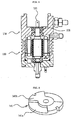
- FIG. 8 is a cross-sectional view illustrating the in-use state of the first embodiment of the oil cooling structure in accordance with the present invention;
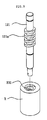
- FIG. 9 is a perspective view illustrating a second embodiment of the oil cooling structure in accordance with the present invention; and
- FIG. 10 is a perspective view illustrating a cooling structure using thermoelectric elements in accordance with the present invention.
- Reference will now be made in greater detail to a preferred embodiment of the invention, an example of which is illustrated in the accompanying drawings. Wherever possible, the same reference numerals will be used throughout the drawings and the description to refer to the same or like parts.
- First, the present invention is directed to a side feeding type external pump in which the suction direction of LPG, that is, working fluid, corresponds to the rotation direction of the pump, and a novel configuration allows the working fluid to flow through the pump, whereby fuel suction efficiency is improved and cooling is enabled to reliably maintain the performance of the pump. Second, the present invention is directed to an oil circulation structure in which an oil circulation line is formed in the rotator installed in a motor of the pump and oil charged in the motor is circulated through the oil circulation line, whereby cooling efficiency is improved. Third, the present invention is directed to a cooling structure in which thermoelectric elements are attached to a flow chamber and/or a rotational force supply section, whereby cooling efficiency is improved.
- First, a side feeding type external pump for LPG in accordance with the present invention will be described with reference to FIG. 1.
- The side feeding type external pump for LPG in accordance with the present invention largely comprises a
flow chamber 110 for sucking working fluid and discharging the working fluid toward an engine and a rotationalforce supply section 120 for supplying rotational force to theflow chamber 110. - A
fluid feeding section 140, which sucks and discharges working fluid by periodically changing the spatial volume thereof, is accommodated in theflow chamber 110. The working fluid is introduced into and discharged from thefluid feeding section 140 through aninlet port 112a and anoutlet port 113a which are mounted to the wall of theflow chamber 110. A rotationalforce supply section 120, in which a motor for rotating thefluid feeding section 140 is built, is provided to one end of theflow chamber 110. Due to this construction, as a working fluid suction direction corresponds to the rotation direction of thefluid feeding section 140, flow resistance is decreased, and working fluid suction efficiency is improved. - At this time, the
flow chamber 110 and the rotationalforce supply section 120 are isolated from each other. This functions to prevent the working fluid made to flow by thefluid feeding section 140 from leaking , into the rotationalforce supply section 120. - Meanwhile, in order to cool the motor built in the rotational
force supply section 120, a refrigerant flows through arefrigerant inlet port 122 which is provided to the wall of the rotationalforce supply section 120 to receive the refrigerant, the motor and arefrigerant discharge section 150 which is mounted to one end of the rotationalforce supply section 120 to discharge the refrigerant. - In the present invention, the working fluid, that is, the LPG fuel, is used as the refrigerant. That is to say, the working fluid is introduced into the
refrigerant inlet port 122 by the internal pressure (of about 2 bars) of a fuel tank filled with the LPG fuel. - Thanks to this construction, the working fluid suction efficiency is improved, and, as the motor is cooled and is prevented from overheating, the functionality of the pump can be reliably maintained.
- Because the LPG fuel does not pass through the motor of the pump, which is hot, but passes only through the flow chamber, a substantial rise in the temperature of the fuel, which is otherwise caused in conventional pumps due to the passage of fuel through the pump, does not occur. As a consequence, it is possible to avoid side effects such as abnormal rises in the temperature and pressure of the fuel and deterioration of durability of the pump.
- Hereafter, the
fluid feeding section 140 will be described with reference to FiGs. 1 and 2. - The
fluid feeding section 140 comprises arotor 142 which is disposed in a donut-shaped cylinder 144,rollers 143 being fitted in therotor 142 on the outer circumference of therotor 142. At this time, as fully disclosed inKorean Patent No. 505821 rotor 142 and therollers 143. - These flow paths, through which the working fluid is sucked and discharged, are defined by a
first plate 141 and asecond plate 145. - In the first and
second plates parts flat parts parts flat parts flat parts second plate 145 is defined through the center portion thereof with ahole 145c through which therotation shaft 121 extending from the motor passes. - The working fluid is fed by the construction of the
fluid feeding section 140 as described above, which will be described below in detail with reference to FIG. 2. - FIG. 2 illustrates a state in which the
first plate 141, thecylinder 144 and thesecond plate 145 are assembled with one another. In order to clearly represent the flow of the working fluid, therotor 142 and therollers 143 which are disposed in thecylinder 144 are not illustrated in the drawing. - By the rotation of the
rotor 142 and therollers 143, the working fluid is sucked through suction gaps 'I' which are defined between theflat part 141a of thefirst plate 141 and thecylinder 144 and between theflat part 145a of thesecond plate 145 and thecylinder 144, and is discharged through discharge gaps '0' which are defined opposite the suction gaps 'I'. - The working fluid, which is fed through the
fluid feeding section 140 as described above, is introduced through theinlet port 112a as shown in FIG. 3. Thereafter, the working fluid is introduced into thefluid feeding section 140 through asuction hole 112b which is defined through the wall of theflow chamber 110 to communicate with theinlet port 112a and the upper part of aspace 111 for accommodating thefluid feeding section 140. Adischarge hole 113b is defined through the wall of theflow chamber 110 beside thesuction hole 112b, and communicates with theoutlet port 113a and the upper part of thespace 111 for accommodating thefluid feeding section 140. - As described above, due to the construction of the
inlet port 112a, thesuction hole 112b, theoutlet port 113a and thedischarge hole 113b, the flowing direction of the working fluid is tangential to the rotating direction of thefluid feeding section 140. As a consequence, at the moment that the working fluid comes into contact with thefluid feeding section 140, as the flowing direction of the working fluid corresponds to the rotating direction of thefluid feeding section 140, the working fluid suction efficiency can be improved. - Meanwhile, as described above, the
flow chamber 110 and the rotationalforce supply section 120 are isolated from each other to prevent the working fluid compressed in theflow chamber 110 from leaking. Therefore, since the working fluid does not flow through the rotationalforce supply section 120, a separate cooling device is required for cooling the rotationalforce supply section 120. - That is to say, as described above, in the conventional internal pump, since the pump is installed in a fuel tank, the pump is cooled by the fuel charged in the fuel tank. However, in the external pump according to the present invention, separate means for performing a cooling function is needed.
- In the present invention, as shown in FIG. 1, by the construction of the
refrigerant inlet port 122, which is provided to the wall of the rotationalforce supply section 120 to receive the refrigerant and therefrigerant discharge section 150, which is mounted to one end of the rotationalforce supply section 120 to discharge the refrigerant, as the refrigerant flows through the rotationalforce supply section 120, the rotationalforce supply section 120 is cooled. Therefrigerant discharge section 150 comprises acover 152 which is mounted to the rotationalforce supply section 120 and arefrigerant outlet port 151 which is mounted to thecover 152. - In particular, in the present invention, the LPG fuel, that is, the working fluid, is used as the refrigerant. The LPG fuel is charged in the fuel tank and has a filling pressure of about 2 bars. The working fluid, that is, the refrigerant, is introduced into the external pump of the present invention by the filling pressure.
- Meanwhile, as described above, the
flow chamber 110 and the rotationalforce supply section 120 are isolated from each other. At this time, as shown in FIG. 3, a rotationshaft passage hole 115 is defined through one end of theflow chamber 110, such that therotation shaft 121, which extends from the motor disposed in the rotationalforce supply section 120 and is connected to thefluid feeding section 140, passes through the rotationshaft passage hole 115. - Due to the presence of the rotation
shaft passage hole 115, the working fluid flowing in theflow chamber 110 may leak into the rotationalforce supply section 120. Therefore, in consideration of this fact, it is preferred that a sealingmember 116 be fitted into the rotationshaft passage hole 115 to prevent the leakage of the working fluid (see FIG. 4). - Hereafter, oil circulation structures for a cooling purpose according to the present invention will be described.
- As is generally known in the art, a motor has a stator installed therein, and a rotator rotates in the stator due to the interaction of current to produce rotational force.
- In the present invention, as an oil circulation line is formed in the rotator and oil is circulated through the oil circulation line, cooling performance can be improved, which will be described through respective embodiments.
- FIG. 6 illustrates a first embodiment, in which an oil circulation line is formed in the shape of a straight line. For the sake of convenience of explanation, in the rotational
force supply section 120, only the rotator R and therotation shaft 121 installed in the rotator R are illustrated. - As can be readily seen from FIG. 6, a first circulation line R10 is formed in the rotator R which is rotated by the stator (not shown). The first circulation line R10 is formed in the rotator R to extend in the shape of the straight line. The first circulation line R10 is maintained throughout its length at the same radial distance from the axis of the rotator R, and the positions of an entrance R11 and an exit R12 which are defined on both ends of the rotator R are not aligned with each other in the axial direction, but deviate from the axis of the rotator R. That is to say, the first circulation line R10 is inclined with respect to the axis of the rotator R while being maintained throughout its length at the same radial distance from the axis of the rotator R. Due to the presence of the first circulation line R10 configured in this way, the oil charged in the motor of the rotational
force supply section 120 can be circulated. Describing the principle with reference to FIG. 7, when the rotator R, which is formed with the first circulation line R10, is rotated, as shown in FIG. 7, the first circulation line R10 compresses the working fluid in a direction 'F' perpendicular to the inner surface of the first circulation line R10. At this time, the compressing force is divided into horizontal component force Ft and vertical component force Fn, and the working fluid is applied with pushing force by the horizontal component force Ft. - Due to this principle, as the working fluid is pushed and discharged through the exit R12, oil is charged again into vacant spaces through the entrance R11. As this phenomenon is repeated, the oil charged in the motor of the rotational
force supply section 120 is circulated through the first circulation line R10. - As a result, as the oil is circulated as described above, oil having received heat performs heat transfer on the surface of the motor of the rotational
force supply section 120 with the atmosphere and thus cools. Then, the cooled oil is circulated and introduced into the first circulation line R10 to considerably improve the cooling efficiency of the motor of the rotational force supply section 120 (see FIG. 8). - Hereinbelow, a second embodiment, in which an oil circulation line is formed in the shape of an external thread will be descried with reference to FIG. 9.
- In this second embodiment, an
external thread 121a is formed on therotation shaft 121 which is fitted into the rotator R, and a second circulation line R20 is formed through the rotator R such that theexternal thread 121a can be threadedly coupled into the second circulation line R20. The relationship between theexternal thread 121a and the second circulation line R20 is similar to that between a bolt and a nut into which the bolt is threadedly coupled. - As the
external thread 121a of therotation shaft 121 is threadedly coupled into and rotated in the second circulation line R20, the oil is fed and circulated through the gap defined between theexternal thread 121a and the second circulation line R20. - Due to this circulation of oil, oil having received heat is circulated to the surface of the rotational
force supply section 120 and dissipates the heat to the atmosphere on the surface of the rotationalforce supply section 120, whereby the cooling of the rotationalforce supply section 120 is effected. - Meanwhile, it is preferred that the circulation lines of the first and second embodiments be applied to a side feeding type external pump. In the case of a general external pump, as the LPG fuel passes through the general external pump, the general external pump is cooled by the LPG fuel.
- However, in the side feeding type external pump as described above, as can be readily seen from FIG. 1, since the LPG fuel is sucked through the
inlet port 112a and is then discharged through theoutlet port 113a, the LPG fuel does not pass through the rotationalforce supply section 120. Accordingly, because the cooling effect as attained in the general external pump by the LPG fuel cannot be anticipated in the side feeding type external pump, it is preferred that the circulation line R10 or R20 be formed in the rotator R of the rotationalforce supply section 120, as in the present invention. - Next, a construction in which a thermoelectric element is installed on the rotational
force supply section 120 and/or theflow chamber 110 to improve cooling performance according to the present invention will be described with reference to FIG. 10. First, describing the structure of the rotationalforce supply section 120, a flattenedpart 120a is formed on a portion of the surface of the rotationalforce supply section 120 to be flat. The surface of the rotationalforce supply section 120 is formed with prominences and depressions to maximally increase the area of contact with the atmosphere. Thanks to this configuration, heat transfer with the atmosphere takes place. In order to attach the thermoelectric element according to the present invention, after a portion of the surface of the rotationalforce supply section 120 which has depressions and prominences is flattened to define the flattenedpart 120a, thethermoelectric element 131 is installed on the flattenedpart 120a. As is well known in the art, thethermoelectric element 131 induces a Peltier effect. That is to say, when joining two metals having different characteristics and then applying a current through the two metals, heat is generated in one junction point, and heat is absorbed in the other junction point. Thethermoelectric element 131 performs a cooling function using this phenomenon. - In the present invention, the heat absorption side of the
thermoelectric element 131 is mounted to the flattenedpart 120a, and aheat dissipation plate 132 is mounted to the heat dissipation side of thethermoelectric element 131. Theheat dissipation plate 132 functions to dissipate the heat absorbed by thethermoelectric element 131 to the outside. In order to improve the performance of theheat dissipation plate 132, theheat dissipation plate 132 is formed to have depressions and prominences. Meanwhile, in order to promote the dissipation of the heat emitted from theheat dissipation plate 132, it is preferable that afan 133 be installed on theheat dissipation plate 132. - As described above, in order to cool the heat generated by the motor, in addition to the fact that the
thermoelectric element 131 is attached to the surface of the rotationalforce supply section 120, it is preferable that a thermoelectric element be installed on theflow chamber 110. - Specifically, as in the case of the rotational
force supply section 120, athermoelectric element 131 is installed on the surface of theflow chamber 110, and aheat dissipation plate 132 and afan 133 are installed on the heat dissipation side of thethermoelectric element 131, whereby the heat generated in theflow chamber 110 can be efficiently dissipated. - As is apparent from the above description, the side feeding type external pump for LPG according to the present invention provides advantages in that, since the suction direction of working fluid corresponds to the rotation direction of the pump and a novel configuration allows the working fluid to flow through the pump, fuel suction efficiency is improved and cooling is enabled, thus reliably maintaining the performance of the pump.
- Also, because the LPG fuel does not pass through the motor of the pump, which is hot, but passes only through a fluid feeding section, a substantial rise in the temperature of the fuel, which is otherwise caused in conventional pumps due to the passage of fuel through the pump, does not result. As a consequence, it is possible to avoid side effects such as abnormal rises in the temperature and pressure of the fuel and the deterioration of durability of the pump.
- Moreover, since oil is circulated through an oil circulation line formed in a rotator, cooling efficiency is improved, and since thermoelectric elements are used, the cooling efficiency can be further improved.
Claims (8)
- A side feeding type external pump for LPG comprising:a fluid feeding section (140) which sucks and discharges working fluid by periodically changing a spatial volume and thereby feeds working fluid;a flow chamber (110) into and from which working fluid is introduced and discharged in a direction tangential to a rotating direction of the fluid feeding section (140);a rotational force supply section (120) in which a motor for supplying rotational force to the fluid feeding section (140) is built and which is isolated from the flow chamber (110);a refrigerant inlet port (122) which is formed in the rotational force supply section (120) to receive a refrigerant and cool the rotational force supply section (120); anda refrigerant discharge section (150) which is mounted to one end of the rotational force supply section (120) to discharge the refrigerant.
- The external pump as set forth in claim 1, wherein the fluid feeding section (140) comprises:a rotor (142) disposed in a cylinder (144) and rotated by a rotation shaft (121) of the rotational force supply section (120) to suck and discharge working fluid, and rollers (143) fitted in the rotor (142) on an outer circumference of the rotor (142);a first plate (141) arrange on one end of the cylinder (144) to provide a flow path for sucking working fluid, and having a disc-shaped flat part (141a) and a projecting part (141b) which projects on a center portion of the disc-shaped flat part (141a) to define a circular shape and projects from the circular shape to opposite edge portions of the disc-shaped flat part (141a) to define sector shapes; anda second plate (145) arranged on the other end of the cylinder (144) to provide a flow path for discharging sucked working fluid, and having a disc-shaped flat part (145a) and a projecting part (145b) which projects on a center portion of the disc-shaped flat part (145a) to define a circular shape and projects from the circular shape to opposite edge portions of the disc-shaped flat part (145a) to define sector shapes, the second plate (145) being defined through a center portion thereof with a hole (145c) through which the rotation shaft (121) of the rotational force supply section (120) passes.
- The external pump as set forth in claim 1, further comprising:a rotation shaft passage hole (115) defined through one end of the flow chamber (110) to allow the rotation shaft (121) extending from the rotational force supply section (120) to pass therethrough; anda sealing member (116) fitted into the rotation shaft passage hole (115).
- The external pump as set forth in claim 1, wherein a suction hole (112b) for introducing working fluid into the fluid feeding section (140) and a discharge hole (113b) for discharging working fluid from the fluid feeding section (140) to the outside are defined through a wall of the flow chamber (110) to communicate with an upper part of a space (111) for accommodating the fluid feeding section (140); and an inlet port (112a) and an outlet port (113a), which communicate with the suction hole (112b) and the discharge hole (113b), respectively, are mounted to the flow chamber (110).
- The external pump as set forth in any one of claims 1 to 4, further comprising:a first circulation line (R10) defined through a rotator (R) installed in the motor of the rotational force supply section (120) such that the first circulation line (R10) linearly extends and is inclined with respect to an axis of the rotator (R) while being maintained throughout its length at the same radial distance from the axis of the rotator (R).
- The external pump as set forth in any one of claims 1 to 4, further comprising:an external thread (121a) formed on the rotation shaft (121) fitted through a rotator (R) of the motor of the rotational force supply section (120); anda second circulation line (R20) formed in the rotator (R) to be threadedly coupled with the external thread (121a).
- The external pump as set forth in any one of claims 1 to 4, further comprising:a flattened part (120a) formed on a portion of an outer surface of the rotational force supply section (120) to be flat;a thermoelectric element (131) mounted to the flattened part (120a);a heat dissipation plate (132) mounted to the thermoelectric element (131); anda fan (133) mounted to the heat dissipation plate (132).
- The external pump as set forth in any one of claims 1 to 4, further comprising:a thermoelectric element (131) mounted to a surface of the flow chamber (110);a heat dissipation plate (132) mounted to the thermoelectric element (131); anda fan (133) mounted to the heat dissipation plate (132).
Applications Claiming Priority (3)
| Application Number | Priority Date | Filing Date | Title |
|---|---|---|---|
| KR1020050130680A KR100573800B1 (en) | 2005-12-27 | 2005-12-27 | External pump for side flow type LLP |
| KR1020060018741A KR100717267B1 (en) | 2006-02-27 | 2006-02-27 | Cooling Structure of External Pump for Elpji Using Thermoelectric Element |
| KR1020060018740A KR100753593B1 (en) | 2006-02-27 | 2006-02-27 | Oil circulation structure of motor part of external pump |
Publications (2)
| Publication Number | Publication Date |
|---|---|
| EP1803921A2 true EP1803921A2 (en) | 2007-07-04 |
| EP1803921A3 EP1803921A3 (en) | 2009-04-08 |
Family
ID=37709554
Family Applications (1)
| Application Number | Title | Priority Date | Filing Date |
|---|---|---|---|
| EP06026716A Withdrawn EP1803921A3 (en) | 2005-12-27 | 2006-12-22 | Side feeding type external pump for lpg |
Country Status (2)
| Country | Link |
|---|---|
| EP (1) | EP1803921A3 (en) |
| JP (1) | JP2007177791A (en) |
Cited By (2)
| Publication number | Priority date | Publication date | Assignee | Title |
|---|---|---|---|---|
| AU2009201350A1 (en) * | 2009-04-07 | 2010-10-21 | Korea Institute Of Machinery & Materials | External Inline LPG Fuel Pump |
| WO2012122361A2 (en) | 2011-03-10 | 2012-09-13 | Waters Technologies Corporation | System and method of cooling a pump head used in chromatography |
Family Cites Families (12)
| Publication number | Priority date | Publication date | Assignee | Title |
|---|---|---|---|---|
| DE3003828A1 (en) * | 1980-02-02 | 1981-08-13 | Robert Bosch Gmbh, 7000 Stuttgart | FUEL SUPPLY UNIT |
| DE3045146A1 (en) * | 1980-11-29 | 1982-07-01 | Nikkiso Co., Ltd., Tokyo | Motorised centrifugal liq. pump unit - has auxiliary second stage pump circulating liq. to cool and lubricate motor without evaporation |
| US5171131A (en) * | 1991-05-14 | 1992-12-15 | Vickers, Incorporated | Power transmission |
| JPH07332829A (en) * | 1994-06-10 | 1995-12-22 | Seiko Instr Inc | Refrigeration equipment |
| JP3522879B2 (en) * | 1995-03-13 | 2004-04-26 | 日産自動車株式会社 | Built-in motor |
| JP2000213490A (en) * | 1999-01-26 | 2000-08-02 | Aisin Seiki Co Ltd | Electric water pump |
| JP2000297767A (en) * | 1999-04-15 | 2000-10-24 | Aiteku Kk | Rotary fluid machine |
| JP2001025209A (en) * | 1999-07-05 | 2001-01-26 | Nissan Motor Co Ltd | Motor rotor |
| KR100376161B1 (en) * | 2001-04-24 | 2003-03-15 | 삼성전자주식회사 | A storage chamber with peltier element |
| KR100408193B1 (en) * | 2001-04-26 | 2003-12-03 | 주식회사 현대오토넷 | A lpg pump |
| JP4013621B2 (en) * | 2002-04-15 | 2007-11-28 | 株式会社ジェイテクト | Electric water pump |
| KR100543128B1 (en) * | 2003-06-23 | 2006-01-20 | 한국기계연구원 | LP liquid fuel pump |
-
2006
- 2006-12-22 EP EP06026716A patent/EP1803921A3/en not_active Withdrawn
- 2006-12-27 JP JP2006353090A patent/JP2007177791A/en active Pending
Cited By (4)
| Publication number | Priority date | Publication date | Assignee | Title |
|---|---|---|---|---|
| AU2009201350A1 (en) * | 2009-04-07 | 2010-10-21 | Korea Institute Of Machinery & Materials | External Inline LPG Fuel Pump |
| WO2012122361A2 (en) | 2011-03-10 | 2012-09-13 | Waters Technologies Corporation | System and method of cooling a pump head used in chromatography |
| EP2683405A4 (en) * | 2011-03-10 | 2015-12-09 | Waters Technologies Corp | SYSTEM AND METHOD FOR COOLING A PUMP HEAD USED IN CHROMATOGRAPHY |
| US9492764B2 (en) | 2011-03-10 | 2016-11-15 | Waters Technologies Corporation | System and method of cooling a pump head used in chromatography |
Also Published As
| Publication number | Publication date |
|---|---|
| EP1803921A3 (en) | 2009-04-08 |
| JP2007177791A (en) | 2007-07-12 |
Similar Documents
| Publication | Publication Date | Title |
|---|---|---|
| US7887285B2 (en) | Pump and fluid supplying apparatus | |
| US10415590B2 (en) | Electric coolant pump | |
| US12230777B2 (en) | Temperature control device for a battery bank module | |
| KR100944147B1 (en) | Scroll compressor with steam injection system | |
| KR101250969B1 (en) | Water pump for vehicle | |
| KR101860345B1 (en) | Motor operated compressor | |
| CN103348141A (en) | Magnetically driven pump arrangement having micropump with forced flushing, and operating method | |
| JPS618492A (en) | Rotary compressor | |
| CN110966228A (en) | Centrifugal compressor | |
| JP2020531738A (en) | Side-channel compressor for fuel cell systems for pumping and / or compressing gaseous media | |
| JP7703403B2 (en) | Heat dissipation and cooling devices | |
| KR102803183B1 (en) | Screw Spindle Pump | |
| KR102803175B1 (en) | Screw Spindle Pump | |
| KR101860355B1 (en) | Motor operated compressor | |
| KR100756529B1 (en) | Lubrication Cooling System for LPG Vehicle Fuel Pump | |
| KR100756528B1 (en) | Lubrication Cooling System for LPG Vehicle Fuel Pump | |
| KR100407501B1 (en) | lubricating device of fuel pump in the LPG vehicles | |
| KR20100042646A (en) | Pump, particularly high-pressure fuel pump | |
| WO2008038894A1 (en) | A waterproof-type motor pump for self-cooling | |
| KR102759504B1 (en) | Electric type Water Pump having Thrust preventing Washer Cooling Element and other Rotating Element`s Cooling Path | |
| CN102084135A (en) | Circulating pump | |
| US20120134868A1 (en) | Rotary sliding-vane compressor | |
| KR101860344B1 (en) | Motor operated compressor | |
| US7690886B2 (en) | Pump and liquid supply apparatus having the pump | |
| US20020094289A1 (en) | Scroll-type compressor with cooling fins included inside a discharge port of a compressed gas |
Legal Events
| Date | Code | Title | Description |
|---|---|---|---|
| PUAI | Public reference made under article 153(3) epc to a published international application that has entered the european phase |
Free format text: ORIGINAL CODE: 0009012 |
|
| 17P | Request for examination filed |
Effective date: 20061222 |
|
| AK | Designated contracting states |
Kind code of ref document: A2 Designated state(s): AT BE BG CH CY CZ DE DK EE ES FI FR GB GR HU IE IS IT LI LT LU LV MC NL PL PT RO SE SI SK TR |
|
| AX | Request for extension of the european patent |
Extension state: AL BA HR MK YU |
|
| PUAL | Search report despatched |
Free format text: ORIGINAL CODE: 0009013 |
|
| AK | Designated contracting states |
Kind code of ref document: A3 Designated state(s): AT BE BG CH CY CZ DE DK EE ES FI FR GB GR HU IE IS IT LI LT LU LV MC NL PL PT RO SE SI SK TR |
|
| AX | Request for extension of the european patent |
Extension state: AL BA HR MK RS |
|
| RIC1 | Information provided on ipc code assigned before grant |
Ipc: F04C 2/344 20060101ALI20090227BHEP Ipc: F02M 37/04 20060101ALI20090227BHEP Ipc: F02M 21/02 20060101AFI20070213BHEP |
|
| AKX | Designation fees paid |
Designated state(s): AT BE BG CH CY CZ DE DK EE ES FI FR GB GR HU IE IS IT LI LT LU LV MC NL PL PT RO SE SI SK TR |
|
| STAA | Information on the status of an ep patent application or granted ep patent |
Free format text: STATUS: THE APPLICATION IS DEEMED TO BE WITHDRAWN |
|
| 18D | Application deemed to be withdrawn |
Effective date: 20100701 |