EP1803524A1 - Laser hardening tool with an optical waveguide having a rectangular cross-sectional shape - Google Patents
Laser hardening tool with an optical waveguide having a rectangular cross-sectional shape Download PDFInfo
- Publication number
- EP1803524A1 EP1803524A1 EP06405536A EP06405536A EP1803524A1 EP 1803524 A1 EP1803524 A1 EP 1803524A1 EP 06405536 A EP06405536 A EP 06405536A EP 06405536 A EP06405536 A EP 06405536A EP 1803524 A1 EP1803524 A1 EP 1803524A1
- Authority
- EP
- European Patent Office
- Prior art keywords
- laser
- optical waveguide
- laser beams
- optical system
- condensing
- Prior art date
- Legal status (The legal status is an assumption and is not a legal conclusion. Google has not performed a legal analysis and makes no representation as to the accuracy of the status listed.)
- Granted
Links
- 230000003287 optical effect Effects 0.000 title claims abstract description 78
- 239000004065 semiconductor Substances 0.000 claims abstract description 17
- 239000000498 cooling water Substances 0.000 claims description 9
- 239000011247 coating layer Substances 0.000 claims description 2
- 239000011159 matrix material Substances 0.000 claims description 2
- 239000011248 coating agent Substances 0.000 description 2
- 238000000576 coating method Methods 0.000 description 2
- 238000001816 cooling Methods 0.000 description 2
- 238000002310 reflectometry Methods 0.000 description 2
- 230000008878 coupling Effects 0.000 description 1
- 238000010168 coupling process Methods 0.000 description 1
- 238000005859 coupling reaction Methods 0.000 description 1
- 230000000694 effects Effects 0.000 description 1
- 238000002474 experimental method Methods 0.000 description 1
- PCHJSUWPFVWCPO-UHFFFAOYSA-N gold Chemical compound [Au] PCHJSUWPFVWCPO-UHFFFAOYSA-N 0.000 description 1
- 239000010931 gold Substances 0.000 description 1
- 229910052737 gold Inorganic materials 0.000 description 1
- 238000010438 heat treatment Methods 0.000 description 1
- 239000013307 optical fiber Substances 0.000 description 1
- 238000007747 plating Methods 0.000 description 1
Images


Classifications
-
- B—PERFORMING OPERATIONS; TRANSPORTING
- B23—MACHINE TOOLS; METAL-WORKING NOT OTHERWISE PROVIDED FOR
- B23K—SOLDERING OR UNSOLDERING; WELDING; CLADDING OR PLATING BY SOLDERING OR WELDING; CUTTING BY APPLYING HEAT LOCALLY, e.g. FLAME CUTTING; WORKING BY LASER BEAM
- B23K26/00—Working by laser beam, e.g. welding, cutting or boring
- B23K26/70—Auxiliary operations or equipment
- B23K26/702—Auxiliary equipment
- B23K26/703—Cooling arrangements
-
- B—PERFORMING OPERATIONS; TRANSPORTING
- B23—MACHINE TOOLS; METAL-WORKING NOT OTHERWISE PROVIDED FOR
- B23K—SOLDERING OR UNSOLDERING; WELDING; CLADDING OR PLATING BY SOLDERING OR WELDING; CUTTING BY APPLYING HEAT LOCALLY, e.g. FLAME CUTTING; WORKING BY LASER BEAM
- B23K26/00—Working by laser beam, e.g. welding, cutting or boring
- B23K26/02—Positioning or observing the workpiece, e.g. with respect to the point of impact; Aligning, aiming or focusing the laser beam
- B23K26/06—Shaping the laser beam, e.g. by masks or multi-focusing
- B23K26/0604—Shaping the laser beam, e.g. by masks or multi-focusing by a combination of beams
-
- B—PERFORMING OPERATIONS; TRANSPORTING
- B23—MACHINE TOOLS; METAL-WORKING NOT OTHERWISE PROVIDED FOR
- B23K—SOLDERING OR UNSOLDERING; WELDING; CLADDING OR PLATING BY SOLDERING OR WELDING; CUTTING BY APPLYING HEAT LOCALLY, e.g. FLAME CUTTING; WORKING BY LASER BEAM
- B23K26/00—Working by laser beam, e.g. welding, cutting or boring
- B23K26/02—Positioning or observing the workpiece, e.g. with respect to the point of impact; Aligning, aiming or focusing the laser beam
- B23K26/06—Shaping the laser beam, e.g. by masks or multi-focusing
- B23K26/062—Shaping the laser beam, e.g. by masks or multi-focusing by direct control of the laser beam
- B23K26/0626—Energy control of the laser beam
-
- B—PERFORMING OPERATIONS; TRANSPORTING
- B23—MACHINE TOOLS; METAL-WORKING NOT OTHERWISE PROVIDED FOR
- B23K—SOLDERING OR UNSOLDERING; WELDING; CLADDING OR PLATING BY SOLDERING OR WELDING; CUTTING BY APPLYING HEAT LOCALLY, e.g. FLAME CUTTING; WORKING BY LASER BEAM
- B23K26/00—Working by laser beam, e.g. welding, cutting or boring
- B23K26/352—Working by laser beam, e.g. welding, cutting or boring for surface treatment
Definitions
- the present invention relates to a hardening tool that utilizes semiconductor laser.
- Japanese Patent Application Laid-Open Publication No. 2003-138314 discloses a laser hardening device proposed by the present applicant.
- Japanese Patent Application Laid-Open Publication No. 2005-238253 discloses a laser hardening tool capable of being attached in removable manner to a tool post of a machine tool.
- the laser beams output from a laser emission source such as a semiconductor laser bar or a semiconductor laser stack are transmitted via an optical fiber or a waveguide to a torch disposed at the end of the tool.
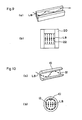
- the prior art laser beam waveguide 10 has an inner surface 12 formed of a cylindrical surface. Since the laser beams LB traveling through the waveguide having the cylindrical surface 12 rotate along the cylindrical surface, the number of reflections is increased. Since the reflectivity of the inner surface of the waveguide is 1.0 or smaller, the efficiency is deteriorated each time the beams are reflected, which causes the laser output to be reduced.
- the present inventors have conducted various experiments on the effect that the cross-sectional shape of the optical waveguide has on the laser output efficiency, and confirmed that an optical waveguide 20 with a rectangular cross-section having its inner surfaces formed of planar surfaces 22 has reduced number of reflections, and thus realizes an optical waveguide having high output efficiency.
- the object of the present invention is to provide a laser hardening tool based on the above-described knowledge.
- the present invention provides a laser hardening tool comprising a semiconductor laser stack having semiconductors arranged in a matrix for outputting laser beams; a condensing optical system for condensing the laser beams output from the semiconductor laser stack; a diverging optical system for diverging the laser beams condensed by the condensing optical system so that the axis line of the laser beams become parallel; a rectangular (square) optical waveguide for guiding the laser beams output from the diverging optical system having a rectangular cross-sectional shape; a re-condensing optical system for re-condensing the laser beams having traveled through the rectangular optical waveguide; and an optical waveguide nozzle for outputting the re-condensed laser beams toward a work.
- the laser hardening tool comprises a first mirror disposed at an inlet port of the rectangular optical waveguide, and a second mirror disposed between the re-condensing optical system and the optical waveguide nozzle.
- the laser hardening tool comprises a cooling water channel for supplying cooling water provided in a lens holder of the condensing optical system, a lens holder of the diverging optical system, the first mirror, the rectangular optical waveguide, a lens holder of the re-condensing optical system, the second mirror and the optical waveguide nozzle; and the mirror surface for reflecting the laser beam is provided with a reflection amplifying coating layer.
- the laser hardening tool of the present invention having the arrangements described above enables to guide the beams output from the semiconductor laser stack to the nozzle with little loss.
- FIG. 1 is a perspective view of a laser hardening tool according to the present invention
- FIG. 2 is a cross-sectional side view showing the whole structure of the laser hardening tool according to the present invention
- FIG. 3 is an upper view of FIG. 2.
- the laser hardening tool denoted as a whole by reference number 100 comprises a semiconductor laser stack 120 mounted on a base 110.
- the semiconductor laser stack 120 has power supply connecting terminals 122, which are connected to a power supply not shown.
- the output of the semiconductor laser stack 120 is sent into a holder 130 having an optical passage 132.
- a condensing optical system (lens) 134 is disposed within the optical passage 132 of the holder 130 for condensing the output beams from the semiconductor laser stack 120.
- the condensed laser beams are entered to a diverging optical lens 142 within a holder 140, where they are diverged so that the axis lines of the beams become parallel.
- the diverged laser beams are sent to a first mirror 160 attached to one end of a rectangular optical waveguide 150.
- the laser beams being turned by the mirror 160 toward the axial direction of the rectangular optical waveguide 150 advance while reflecting on a reflecting surface 152 on the inner side of the rectangular optical waveguide 150, and enter a re-condensing optical lens 170 within a holder 172.
- the laser beams passing through the rectangular optical waveguide 150 have reduced number of reflections compared to the beams passing through the prior-art optical waveguide with a circular cross-section, and thus the beams are subjected to less attenuation.
- the laser beams being re-condensed by the re-condensing optical lens 170 have their axis line changed for 90 degrees by a second mirror 180, and are irradiated through an optical waveguide nozzle 190 to subject a surface of a work not shown to hardening treatment.
- the laser hardening tool 100 is heated by absorbing the laser beams passing therethrough. It is further subjected to external heating via the reflected heat from the work being hardened by the laser hardening tool.
- the laser hardening tool 100 has a cooling channel for preventing temperature rise.
- FIG. 4 is a cross-sectional side view of the cooling channel provided in the laser hardening tool 100, and FIG. 5 is an upper view of FIG. 4.
- the holder 130 of the condensing optical lens 134 includes a channel 136 through which cooling water passes, which is connected via a coupling 202 to a pipe 200 for supplying and draining the cooling water.
- the holder 140 of the diverging optical lens 142 also includes a channel 144, and the channel 144 is communicated via a channel 164 of the first mirror 160 to a channel 154 of the rectangular optical waveguide 150.
- the holder 172 of the re-condensing optical lens 170 includes a channel 174.
- the second mirror 180 also includes a channel 184, and the optical waveguide nozzle 190 includes a channel 194.
- the laser hardening tool 100 can be effectively cooled by circulating cooling water supplied via the pipe 200 from a cooling water supply not shown throughout the whole laser hardening tool 100 via the channels.
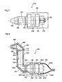
- FIG. 6 is an explanatory view showing the layout of the optical lens 134, 142 and 170, mirror surfaces 160M and 180M of the mirrors 160 and 180, a rectangular planar mirror surface 150M of the rectangular optical waveguide 150, and a circular conic mirror surface 190M on the inner surface of the optical waveguide nozzle 190 of the laser hardening tool 100.
- a reflection amplifying coating is applied to the mirror surfaces in order to enhance the reflectivity.
- Gold plating is adopted for example as the reflection amplifying coating.
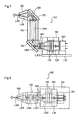
- FIG. 7 is a cross-sectional side view showing the laser passage of a laser hardening tool 100 according to the present invention
- FIG. 8 is an upper view of FIG. 7.
- the laser beams LB 1 irradiated from the semiconductor laser stack 120 are condensed by the condensing optical lens 134, become laser beams LB 2 and enter the diverging optical lens 142.
- the laser beams LB 3 having exited the diverging optical lens 142 are bent orthogonally via the mirror 160 substantially as parallel light, and travel through the rectangular optical waveguide 150 as laser beams LB 4 .
- the laser beams LB 4 passing through the rectangular optical waveguide 150 are subjected to smaller number of reflections, and thus the loss thereof is small.
- the axis line of the introduction light can be made as parallel as possible with the axis line of the rectangular optical waveguide 150.
- the laser beams having passed through the rectangular optical waveguide 150 are condensed by the re-condensing optical lens 170 and bent for 90 degrees by the mirror 180.
- the laser beams LB 5 are narrowed down inside the optical waveguide nozzle 190 and output as laser beams LB 6 .
- the laser beams LB 6 perform hardening of the surface of a work not shown.
- the laser beams from the semiconductor laser stack 120 can be output from the optical waveguide nozzle 190 with only small loss occurring on the way, so an effective hardening treatment can be realized.
- the shape of the leading opening of the optical waveguide nozzle 190 is round, but the shape thereof can be designed appropriately by assembling triangles, squares, polygons and curves for example to correspond to the shape of the work or the shape of the hardening portion.
- the axis line of the nozzle can be bent instead of being in a straight line.
Landscapes
- Physics & Mathematics (AREA)
- Optics & Photonics (AREA)
- Engineering & Computer Science (AREA)
- Plasma & Fusion (AREA)
- Mechanical Engineering (AREA)
- Laser Beam Processing (AREA)
- Lasers (AREA)
- Semiconductor Lasers (AREA)
- Heat Treatment Of Articles (AREA)
- Microscoopes, Condenser (AREA)
Abstract
Description
- The present invention relates to a hardening tool that utilizes semiconductor laser.
- For example,
Japanese Patent Application Laid-Open Publication No. 2003-138314 Japanese Patent Application Laid-Open Publication No. 2005-238253 - According to these laser hardening tools, the laser beams output from a laser emission source such as a semiconductor laser bar or a semiconductor laser stack are transmitted via an optical fiber or a waveguide to a torch disposed at the end of the tool.
- As shown in FIG. 10, the prior art
laser beam waveguide 10 has aninner surface 12 formed of a cylindrical surface. Since the laser beams LB traveling through the waveguide having thecylindrical surface 12 rotate along the cylindrical surface, the number of reflections is increased. Since the reflectivity of the inner surface of the waveguide is 1.0 or smaller, the efficiency is deteriorated each time the beams are reflected, which causes the laser output to be reduced. - The present inventors have conducted various experiments on the effect that the cross-sectional shape of the optical waveguide has on the laser output efficiency, and confirmed that an
optical waveguide 20 with a rectangular cross-section having its inner surfaces formed ofplanar surfaces 22 has reduced number of reflections, and thus realizes an optical waveguide having high output efficiency. - The object of the present invention is to provide a laser hardening tool based on the above-described knowledge.
- In order to achieve the above object, the present invention provides a laser hardening tool comprising a semiconductor laser stack having semiconductors arranged in a matrix for outputting laser beams; a condensing optical system for condensing the laser beams output from the semiconductor laser stack; a diverging optical system for diverging the laser beams condensed by the condensing optical system so that the axis line of the laser beams become parallel; a rectangular (square) optical waveguide for guiding the laser beams output from the diverging optical system having a rectangular cross-sectional shape; a re-condensing optical system for re-condensing the laser beams having traveled through the rectangular optical waveguide; and an optical waveguide nozzle for outputting the re-condensed laser beams toward a work.
- Further, the laser hardening tool comprises a first mirror disposed at an inlet port of the rectangular optical waveguide, and a second mirror disposed between the re-condensing optical system and the optical waveguide nozzle.
- Moreover, the laser hardening tool comprises a cooling water channel for supplying cooling water provided in a lens holder of the condensing optical system, a lens holder of the diverging optical system, the first mirror, the rectangular optical waveguide, a lens holder of the re-condensing optical system, the second mirror and the optical waveguide nozzle; and the mirror surface for reflecting the laser beam is provided with a reflection amplifying coating layer.
- The laser hardening tool of the present invention having the arrangements described above enables to guide the beams output from the semiconductor laser stack to the nozzle with little loss.
-
- FIG. 1 is a perspective view of a laser hardening tool according to the present invention;
- FIG. 2 is a cross-sectional side view of the laser hardening tool according to the present invention;
- FIG. 3 is an upper view of FIG. 2;
- FIG. 4 is a cross-sectional side view of the cooling water channel of the laser hardening tool of the present invention;
- FIG. 5 is an upper view of FIG. 4;
- FIG. 6 is a cross-sectional side view showing the arrangement of mirrors of the laser hardening tool according to the present invention;
- FIG. 7 is a cross-sectional side view illustrating the flow of laser beam of the laser hardening tool according to the present invention;
- FIG. 8 is an upper view of FIG. 7;
- FIG. 9 is an explanatory view showing the operation of the rectangular optical waveguide according to the present invention; and
- FIG. 10 is an explanatory view showing the operation of a prior art optical waveguide.
- FIG. 1 is a perspective view of a laser hardening tool according to the present invention, FIG. 2 is a cross-sectional side view showing the whole structure of the laser hardening tool according to the present invention, and FIG. 3 is an upper view of FIG. 2.
- The laser hardening tool denoted as a whole by
reference number 100 comprises asemiconductor laser stack 120 mounted on abase 110. Thesemiconductor laser stack 120 has powersupply connecting terminals 122, which are connected to a power supply not shown. - The output of the
semiconductor laser stack 120 is sent into aholder 130 having anoptical passage 132. A condensing optical system (lens) 134 is disposed within theoptical passage 132 of theholder 130 for condensing the output beams from thesemiconductor laser stack 120. - The condensed laser beams are entered to a diverging
optical lens 142 within aholder 140, where they are diverged so that the axis lines of the beams become parallel. The diverged laser beams are sent to afirst mirror 160 attached to one end of a rectangularoptical waveguide 150. The laser beams being turned by themirror 160 toward the axial direction of the rectangularoptical waveguide 150 advance while reflecting on areflecting surface 152 on the inner side of the rectangularoptical waveguide 150, and enter a re-condensingoptical lens 170 within aholder 172. - The laser beams passing through the rectangular
optical waveguide 150 have reduced number of reflections compared to the beams passing through the prior-art optical waveguide with a circular cross-section, and thus the beams are subjected to less attenuation. - The laser beams being re-condensed by the re-condensing
optical lens 170 have their axis line changed for 90 degrees by asecond mirror 180, and are irradiated through anoptical waveguide nozzle 190 to subject a surface of a work not shown to hardening treatment. - The
laser hardening tool 100 is heated by absorbing the laser beams passing therethrough. It is further subjected to external heating via the reflected heat from the work being hardened by the laser hardening tool. - Thus, the
laser hardening tool 100 according to the present invention has a cooling channel for preventing temperature rise. - FIG. 4 is a cross-sectional side view of the cooling channel provided in the
laser hardening tool 100, and FIG. 5 is an upper view of FIG. 4. - The
holder 130 of the condensingoptical lens 134 includes achannel 136 through which cooling water passes, which is connected via acoupling 202 to apipe 200 for supplying and draining the cooling water. - The
holder 140 of the divergingoptical lens 142 also includes achannel 144, and thechannel 144 is communicated via achannel 164 of thefirst mirror 160 to achannel 154 of the rectangularoptical waveguide 150. Theholder 172 of the re-condensingoptical lens 170 includes achannel 174. Thesecond mirror 180 also includes achannel 184, and theoptical waveguide nozzle 190 includes achannel 194. - The
laser hardening tool 100 can be effectively cooled by circulating cooling water supplied via thepipe 200 from a cooling water supply not shown throughout the wholelaser hardening tool 100 via the channels. - FIG. 6 is an explanatory view showing the layout of the
optical lens mirror surfaces 160M and 180M of themirrors planar mirror surface 150M of the rectangularoptical waveguide 150, and a circularconic mirror surface 190M on the inner surface of theoptical waveguide nozzle 190 of thelaser hardening tool 100. - A reflection amplifying coating is applied to the mirror surfaces in order to enhance the reflectivity. Gold plating is adopted for example as the reflection amplifying coating.
- FIG. 7 is a cross-sectional side view showing the laser passage of a
laser hardening tool 100 according to the present invention, and FIG. 8 is an upper view of FIG. 7. - The laser beams LB1 irradiated from the
semiconductor laser stack 120 are condensed by the condensingoptical lens 134, become laser beams LB2 and enter the divergingoptical lens 142. - The laser beams LB3 having exited the diverging
optical lens 142 are bent orthogonally via themirror 160 substantially as parallel light, and travel through the rectangularoptical waveguide 150 as laser beams LB4. The laser beams LB4 passing through the rectangularoptical waveguide 150 are subjected to smaller number of reflections, and thus the loss thereof is small. - By providing a diverging optical lens at the entrance of the rectangular
optical waveguide 150 and appropriately designing the curvature of the lens, the axis line of the introduction light can be made as parallel as possible with the axis line of the rectangularoptical waveguide 150. - According to this means, it becomes possible to reduce the number of reflections of the laser beams within the rectangular
optical waveguide 150 and reduce energy loss. - Furthermore, by increasing the size of the rectangular
optical waveguide 150 as much as possible, it becomes possible to reduce the number of reflections of the laser beams traveling therethrough. - The laser beams having passed through the rectangular
optical waveguide 150 are condensed by the re-condensingoptical lens 170 and bent for 90 degrees by themirror 180. - The laser beams LB5 are narrowed down inside the
optical waveguide nozzle 190 and output as laser beams LB6. The laser beams LB6 perform hardening of the surface of a work not shown. - According to the
laser hardening tool 100 of the present invention, the laser beams from thesemiconductor laser stack 120 can be output from theoptical waveguide nozzle 190 with only small loss occurring on the way, so an effective hardening treatment can be realized. - According to the above-mentioned embodiment, the shape of the leading opening of the
optical waveguide nozzle 190 is round, but the shape thereof can be designed appropriately by assembling triangles, squares, polygons and curves for example to correspond to the shape of the work or the shape of the hardening portion. - Moreover, the axis line of the nozzle can be bent instead of being in a straight line.
Claims (4)
- A laser hardening tool comprising:a semiconductor laser stack having semiconductors arranged in a matrix for outputting laser beams;a condensing optical system for condensing the laser beams output from the semiconductor laser stack;a diverging optical system for diverging the laser beams condensed by the condensing optical system so that the axis lines of the laser beams become parallel;a rectangular optical waveguide for guiding the laser beams output from the diverging optical system having a rectangular cross-sectional shape;a re-condensing optical system for re-condensing the laser beams having traveled through the rectangular optical waveguide; andan optical waveguide nozzle for outputting the re-condensed laser beams toward a work.
- The laser hardening tool according to claim 1, further comprising a first mirror disposed at an inlet port of the rectangular optical waveguide, and a second mirror disposed between the re-condensing optical system and the optical waveguide nozzle.
- The laser hardening tool according to claim 1, further comprising a cooling water channel for supplying cooling water provided in a lens holder of the condensing optical system, a lens holder of the diverging optical system, the first mirror, the rectangular optical waveguide, a lens holder of the re-condensing optical system, the second mirror and the optical waveguide nozzle.
- The laser hardening tool according to claim 1, wherein a mirror surface for reflecting the laser beam is provided with a reflection amplifying coating layer.
Applications Claiming Priority (1)
| Application Number | Priority Date | Filing Date | Title |
|---|---|---|---|
| JP2005378955A JP4865329B2 (en) | 2005-12-28 | 2005-12-28 | Laser hardening tool |
Publications (2)
| Publication Number | Publication Date |
|---|---|
| EP1803524A1 true EP1803524A1 (en) | 2007-07-04 |
| EP1803524B1 EP1803524B1 (en) | 2011-04-20 |
Family
ID=37890314
Family Applications (1)
| Application Number | Title | Priority Date | Filing Date |
|---|---|---|---|
| EP06405536A Ceased EP1803524B1 (en) | 2005-12-28 | 2006-12-20 | Laser hardening tool with an optical waveguide having a rectangular cross-sectional shape |
Country Status (5)
| Country | Link |
|---|---|
| US (1) | US7376329B2 (en) |
| EP (1) | EP1803524B1 (en) |
| JP (1) | JP4865329B2 (en) |
| CN (1) | CN100477418C (en) |
| DE (1) | DE602006021386D1 (en) |
Families Citing this family (5)
| Publication number | Priority date | Publication date | Assignee | Title |
|---|---|---|---|---|
| DE102010047917A1 (en) * | 2010-10-08 | 2012-04-12 | Jenoptik Automatisierungstechnik Gmbh | Device for simultaneous circumferential machining of a workpiece with laser beams |
| US9579750B2 (en) * | 2011-10-05 | 2017-02-28 | Applied Materials, Inc. | Particle control in laser processing systems |
| JP6793481B2 (en) * | 2016-06-30 | 2020-12-02 | 浜松ホトニクス株式会社 | Quenching laser processing equipment and quenching laser head |
| CN107813060A (en) * | 2016-08-30 | 2018-03-20 | 奔腾激光(温州)有限公司 | A kind of optical-fiber laser cutting machine reflective cutting head and control method |
| JP7158994B2 (en) * | 2018-10-16 | 2022-10-24 | オークマ株式会社 | Machine Tools |
Citations (5)
| Publication number | Priority date | Publication date | Assignee | Title |
|---|---|---|---|---|
| JPH0371990A (en) * | 1989-08-07 | 1991-03-27 | Mitsubishi Heavy Ind Ltd | Reflecting mirror for laser |
| US20030021579A1 (en) * | 2001-05-11 | 2003-01-30 | Kenichiro Shinoda | Illumination apparatus, exposure apparatus using the same and device fabrication method |
| JP2004243406A (en) * | 2003-02-17 | 2004-09-02 | Yamazaki Mazak Corp | Laser beam machine |
| US20050031261A1 (en) * | 2003-08-04 | 2005-02-10 | Semiconductor Energy Laboratory Co., Ltd. | Beam homogenizer, laser irradiation apparatus and method for manufacturing semiconductor device |
| EP1577993A1 (en) * | 2004-02-24 | 2005-09-21 | Yamazaki Mazak Kabushiki Kaisha | Laser beam generating unit |
Family Cites Families (15)
| Publication number | Priority date | Publication date | Assignee | Title |
|---|---|---|---|---|
| JPH02175090A (en) * | 1988-12-27 | 1990-07-06 | Isamu Miyamoto | Laser beam forming machine |
| JPH05329675A (en) * | 1992-05-27 | 1993-12-14 | Hoya Corp | Laser beam machine |
| JPH071168A (en) * | 1993-06-16 | 1995-01-06 | Nissan Motor Co Ltd | Laser processing machine |
| JPH08187587A (en) * | 1994-12-28 | 1996-07-23 | Ishikawajima Harima Heavy Ind Co Ltd | Laser fillet welding method and device for T-joint |
| JP3313257B2 (en) * | 1995-02-24 | 2002-08-12 | 日本軽金属株式会社 | Parabolic mirror processing head and laser processing machine |
| JP2000107879A (en) * | 1998-10-05 | 2000-04-18 | Amada Co Ltd | Laser cutting method and laser nozzle used in its method |
| JP3816248B2 (en) * | 1998-10-19 | 2006-08-30 | ヤマザキマザック株式会社 | Laser processing machine |
| JP2000202677A (en) * | 1999-01-11 | 2000-07-25 | Mitsubishi Heavy Ind Ltd | Laser beam machining head |
| US6385371B1 (en) * | 2000-04-03 | 2002-05-07 | Cogent Light Technologies, Inc. | Optical system including coupling for transmitting light between a single fiber light guide and multiple single fiber light guides |
| JP2003138314A (en) * | 2001-10-30 | 2003-05-14 | Yamazaki Mazak Corp | Laser hardening device |
| JP2003200285A (en) * | 2001-12-28 | 2003-07-15 | Honda Motor Co Ltd | YAG laser processing head |
| US6824278B2 (en) * | 2002-03-15 | 2004-11-30 | Memx, Inc. | Self-shadowing MEM structures |
| JP2004319820A (en) * | 2003-04-17 | 2004-11-11 | Tsunehiko Yamazaki | Laser beam generating device |
| JP4431420B2 (en) | 2004-02-24 | 2010-03-17 | ヤマザキマザック株式会社 | Machine Tools |
| JP4390627B2 (en) * | 2004-05-28 | 2009-12-24 | ヤマザキマザック株式会社 | Laser hardening tool |
-
2005
- 2005-12-28 JP JP2005378955A patent/JP4865329B2/en not_active Expired - Lifetime
-
2006
- 2006-12-15 US US11/611,243 patent/US7376329B2/en active Active
- 2006-12-20 EP EP06405536A patent/EP1803524B1/en not_active Ceased
- 2006-12-20 DE DE602006021386T patent/DE602006021386D1/en active Active
- 2006-12-26 CN CNB2006101725121A patent/CN100477418C/en not_active Expired - Fee Related
Patent Citations (5)
| Publication number | Priority date | Publication date | Assignee | Title |
|---|---|---|---|---|
| JPH0371990A (en) * | 1989-08-07 | 1991-03-27 | Mitsubishi Heavy Ind Ltd | Reflecting mirror for laser |
| US20030021579A1 (en) * | 2001-05-11 | 2003-01-30 | Kenichiro Shinoda | Illumination apparatus, exposure apparatus using the same and device fabrication method |
| JP2004243406A (en) * | 2003-02-17 | 2004-09-02 | Yamazaki Mazak Corp | Laser beam machine |
| US20050031261A1 (en) * | 2003-08-04 | 2005-02-10 | Semiconductor Energy Laboratory Co., Ltd. | Beam homogenizer, laser irradiation apparatus and method for manufacturing semiconductor device |
| EP1577993A1 (en) * | 2004-02-24 | 2005-09-21 | Yamazaki Mazak Kabushiki Kaisha | Laser beam generating unit |
Also Published As
| Publication number | Publication date |
|---|---|
| JP4865329B2 (en) | 2012-02-01 |
| EP1803524B1 (en) | 2011-04-20 |
| US7376329B2 (en) | 2008-05-20 |
| CN1990886A (en) | 2007-07-04 |
| JP2007180385A (en) | 2007-07-12 |
| US20070158318A1 (en) | 2007-07-12 |
| CN100477418C (en) | 2009-04-08 |
| DE602006021386D1 (en) | 2011-06-01 |
Similar Documents
| Publication | Publication Date | Title |
|---|---|---|
| US8835804B2 (en) | Beam homogenizer | |
| JP6188913B2 (en) | Laser equipment | |
| US5633967A (en) | Waveguide fiber optical coupler | |
| CN108602157B (en) | Optical fiber coupling device | |
| JP6730373B2 (en) | Optical multiple reflection container | |
| US7432471B2 (en) | Laser beam hardening tool | |
| EP3767350B1 (en) | Optical fiber bundle provided with beam superposing mechanism | |
| US7376329B2 (en) | Laser hardening tool | |
| JP2005032579A (en) | Vehicle lighting | |
| JP3932982B2 (en) | Condensing optical circuit and light source device | |
| EP1842928A1 (en) | Laser hardening method | |
| KR20190001631A (en) | Optical System for Changing Homogenized Laser Beam Size | |
| EP1703601A1 (en) | Fiber laser oscillator | |
| CN104136961B (en) | High power laser system | |
| JP7558359B1 (en) | Laser processing machine | |
| JP7431756B2 (en) | Optical arrangement and laser system | |
| KR20180010372A (en) | Laser processing head | |
| WO2021241313A1 (en) | Laser processing device | |
| CN111757804B (en) | Waveguide for narrow synchronous laser plastic welding | |
| JP6188912B2 (en) | Laser equipment | |
| JP2007531028A (en) | Optical device for forming a beam, for example a laser beam | |
| CN108884978A (en) | For the light source of lighting device and the lighting device with such light source | |
| JP4837381B2 (en) | Laser marking device | |
| JP2002374031A (en) | Focusing system for semiconductor laser | |
| JP7739942B2 (en) | laser device |
Legal Events
| Date | Code | Title | Description |
|---|---|---|---|
| PUAI | Public reference made under article 153(3) epc to a published international application that has entered the european phase |
Free format text: ORIGINAL CODE: 0009012 |
|
| AK | Designated contracting states |
Kind code of ref document: A1 Designated state(s): AT BE BG CH CY CZ DE DK EE ES FI FR GB GR HU IE IS IT LI LT LU LV MC NL PL PT RO SE SI SK TR |
|
| AX | Request for extension of the european patent |
Extension state: AL BA HR MK YU |
|
| RAP1 | Party data changed (applicant data changed or rights of an application transferred) |
Owner name: YAMAZAKI MAZAK CORPORATION |
|
| 17P | Request for examination filed |
Effective date: 20070816 |
|
| 17Q | First examination report despatched |
Effective date: 20070925 |
|
| AKX | Designation fees paid |
Designated state(s): DE FR GB IT |
|
| GRAP | Despatch of communication of intention to grant a patent |
Free format text: ORIGINAL CODE: EPIDOSNIGR1 |
|
| GRAS | Grant fee paid |
Free format text: ORIGINAL CODE: EPIDOSNIGR3 |
|
| GRAA | (expected) grant |
Free format text: ORIGINAL CODE: 0009210 |
|
| AK | Designated contracting states |
Kind code of ref document: B1 Designated state(s): DE FR GB IT |
|
| REG | Reference to a national code |
Ref country code: GB Ref legal event code: FG4D |
|
| REF | Corresponds to: |
Ref document number: 602006021386 Country of ref document: DE Date of ref document: 20110601 Kind code of ref document: P |
|
| REG | Reference to a national code |
Ref country code: DE Ref legal event code: R096 Ref document number: 602006021386 Country of ref document: DE Effective date: 20110601 |
|
| PLBE | No opposition filed within time limit |
Free format text: ORIGINAL CODE: 0009261 |
|
| STAA | Information on the status of an ep patent application or granted ep patent |
Free format text: STATUS: NO OPPOSITION FILED WITHIN TIME LIMIT |
|
| 26N | No opposition filed |
Effective date: 20120123 |
|
| REG | Reference to a national code |
Ref country code: DE Ref legal event code: R097 Ref document number: 602006021386 Country of ref document: DE Effective date: 20120123 |
|
| REG | Reference to a national code |
Ref country code: FR Ref legal event code: PLFP Year of fee payment: 10 |
|
| REG | Reference to a national code |
Ref country code: FR Ref legal event code: PLFP Year of fee payment: 11 |
|
| REG | Reference to a national code |
Ref country code: FR Ref legal event code: PLFP Year of fee payment: 12 |
|
| PGFP | Annual fee paid to national office [announced via postgrant information from national office to epo] |
Ref country code: IT Payment date: 20201110 Year of fee payment: 15 Ref country code: FR Payment date: 20201112 Year of fee payment: 15 |
|
| PG25 | Lapsed in a contracting state [announced via postgrant information from national office to epo] |
Ref country code: FR Free format text: LAPSE BECAUSE OF NON-PAYMENT OF DUE FEES Effective date: 20211231 |
|
| PG25 | Lapsed in a contracting state [announced via postgrant information from national office to epo] |
Ref country code: IT Free format text: LAPSE BECAUSE OF NON-PAYMENT OF DUE FEES Effective date: 20211220 |
|
| PGFP | Annual fee paid to national office [announced via postgrant information from national office to epo] |
Ref country code: GB Payment date: 20221027 Year of fee payment: 17 Ref country code: DE Payment date: 20221102 Year of fee payment: 17 |
|
| REG | Reference to a national code |
Ref country code: DE Ref legal event code: R119 Ref document number: 602006021386 Country of ref document: DE |
|
| GBPC | Gb: european patent ceased through non-payment of renewal fee |
Effective date: 20231220 |
|
| PG25 | Lapsed in a contracting state [announced via postgrant information from national office to epo] |
Ref country code: DE Free format text: LAPSE BECAUSE OF NON-PAYMENT OF DUE FEES Effective date: 20240702 |
|
| PG25 | Lapsed in a contracting state [announced via postgrant information from national office to epo] |
Ref country code: GB Free format text: LAPSE BECAUSE OF NON-PAYMENT OF DUE FEES Effective date: 20231220 |
|
| PG25 | Lapsed in a contracting state [announced via postgrant information from national office to epo] |
Ref country code: GB Free format text: LAPSE BECAUSE OF NON-PAYMENT OF DUE FEES Effective date: 20231220 Ref country code: DE Free format text: LAPSE BECAUSE OF NON-PAYMENT OF DUE FEES Effective date: 20240702 |