EP1803499A1 - Sample tube holder - Google Patents
Sample tube holder Download PDFInfo
- Publication number
- EP1803499A1 EP1803499A1 EP05077994A EP05077994A EP1803499A1 EP 1803499 A1 EP1803499 A1 EP 1803499A1 EP 05077994 A EP05077994 A EP 05077994A EP 05077994 A EP05077994 A EP 05077994A EP 1803499 A1 EP1803499 A1 EP 1803499A1
- Authority
- EP
- European Patent Office
- Prior art keywords
- sample tube
- chamber
- tube holder
- array
- symmetry axis
- Prior art date
- Legal status (The legal status is an assumption and is not a legal conclusion. Google has not performed a legal analysis and makes no representation as to the accuracy of the status listed.)
- Withdrawn
Links
Images




Classifications
-
- B—PERFORMING OPERATIONS; TRANSPORTING
- B01—PHYSICAL OR CHEMICAL PROCESSES OR APPARATUS IN GENERAL
- B01L—CHEMICAL OR PHYSICAL LABORATORY APPARATUS FOR GENERAL USE
- B01L9/00—Supporting devices; Holding devices
- B01L9/06—Test-tube stands; Test-tube holders
-
- G—PHYSICS
- G01—MEASURING; TESTING
- G01N—INVESTIGATING OR ANALYSING MATERIALS BY DETERMINING THEIR CHEMICAL OR PHYSICAL PROPERTIES
- G01N35/00—Automatic analysis not limited to methods or materials provided for in any single one of groups G01N1/00 - G01N33/00; Handling materials therefor
- G01N35/02—Automatic analysis not limited to methods or materials provided for in any single one of groups G01N1/00 - G01N33/00; Handling materials therefor using a plurality of sample containers moved by a conveyor system past one or more treatment or analysis stations
- G01N35/026—Automatic analysis not limited to methods or materials provided for in any single one of groups G01N1/00 - G01N33/00; Handling materials therefor using a plurality of sample containers moved by a conveyor system past one or more treatment or analysis stations having blocks or racks of reaction cells or cuvettes
-
- B—PERFORMING OPERATIONS; TRANSPORTING
- B01—PHYSICAL OR CHEMICAL PROCESSES OR APPARATUS IN GENERAL
- B01L—CHEMICAL OR PHYSICAL LABORATORY APPARATUS FOR GENERAL USE
- B01L2200/00—Solutions for specific problems relating to chemical or physical laboratory apparatus
- B01L2200/02—Adapting objects or devices to another
- B01L2200/023—Adapting objects or devices to another adapted for different sizes of tubes, tips or container
-
- B—PERFORMING OPERATIONS; TRANSPORTING
- B01—PHYSICAL OR CHEMICAL PROCESSES OR APPARATUS IN GENERAL
- B01L—CHEMICAL OR PHYSICAL LABORATORY APPARATUS FOR GENERAL USE
- B01L2200/00—Solutions for specific problems relating to chemical or physical laboratory apparatus
- B01L2200/02—Adapting objects or devices to another
- B01L2200/025—Align devices or objects to ensure defined positions relative to each other
Definitions
- the invention concerns a sample tube holder according to the preamble of claim 1.
- a known sample tube holder used in clinical chemistry analyzer comprises a rectilinear array of chambers, each of which is adapted for receiving and holding in place a sample tube. All chambers of the array have the same shape and dimensions.
- the length symmetry axis of all chambers of the sample tube holder lie in one and the same plane, e.g. in a symmetry plane of the rectilinear array of chambers of the sample tube holder.
- each of the chambers of a known sample tube holder includes an elastic tongue which extends from the inner surface of a side wall of the chamber with an inclination towards the center thereof and which presses each sample tube against a side wall of the chamber.
- the length symmetry axis of the sample tubes are not aligned and lie at different distances from the plane which contains the length symmetry axis of the chambers of the sample tube holder.
- Sample tubes having a diameter close to the inner diameter of the chambers of the sample tube holder where they are inserted are approximately centered in those chambers, whereas the centers of smaller sample tubes clearly lie out of the centers of the chambers where they are inserted.
- each of the chambers of the sample tube holder include four elastic tongues with an angular spacing of 90 degrees between them and these tongues press the sample tube towards the length symmetry axis of the chamber.
- the prior art sample tube holders described above are not suitable for use in an analyzer where it is necessary that every one of the sample tubes is accurately centered in a chamber of the sample tube holder and that the length symmetry axis of all sample tubes inserted in the sample tube holder are accurately aligned and lie in the symmetry plane of the sample tube holder. This is for instance required if the sample tube holder is used in an analyzer having an automatic pipetting unit which moves the pipetting needle only along a rectilinear path which lies in the symmetry plane of the array of chambers of the sample tube holder.
- An aim of the invention is to provide a sample tube holder of the above mentioned kind wherein each chamber of the holder includes means for accurately centering sample tubes of different diameters so that the length symmetry axis of each sample tube inserted in a chamber of the sample tube holder coincides with the length symmetry axis of the chamber of the sample tube holder in which the sample tube is positioned, and thereby the length symmetry axis of all sample tubes in the sample holder are aligned and lie in the plane which contains the length symmetry axis of all the chambers of the sample tube holder.
- the main advantages obtained with a sample tube holder according to the invention are that it provides a low cost means for accurately centering each sample tube in the chamber of the sample tube holder where the sample tube is inserted and also contributes to reduce the manufacturing cost of the analyzer by making possible use of a low cost automatic pipetting unit which moves the pipetting needle only along a rectilinear path which lies in the symmetry plane of the array of chambers of the sample tube holder, instead of e.g. a more expensive automatic pipetting unit which moves the pipetting needle in three directions (X, Y, Z) orthogonal to each other.
- sample tube holder Preferred embodiments of a sample tube holder according to the invention are described hereinafter with reference to Figures 1 to 10.
- Such a sample tube holder is adapted for receiving and holding a plurality of sample tubes 21 having a cylindrical shape and outer diameters lying in a predetermined range, e.g. in a range going from about 11 to about 16 millimeter.
- Each of sample tubes 21 has a length symmetry axis 23.
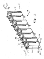
- a sample tube holder according to the invention comprises a solid body 12 defining a rectilinear array of elongated chambers 13 and elastic means 31, 32 associated with and located outside of each chamber 13 of the array.
- Solid body 12 is preferably made by injection molding of a suitable a plastic material.
- Elastic means 31 and 32 are adapted for centering each sample tube 21 arranged in a chamber so that the length symmetry axis 23 of the sample tube coincides with the length symmetry axis 17 of the chamber 13.
- Chambers 13 have each the same shape and dimensions.
- Each chamber 13 has side walls 14, an upper opening 15, a lower opening 16 and a length symmetry axis 17.
- Each chamber 13 is adapted for receiving a longitudinal portion of a sample tube 21.
- solid body 12 comprises for each of chambers 13 a first array of pins, e.g. pins 41, 42, 43 in Fig. 1, which are e.g. longitudinal projections of the side walls 14 of chamber 13 and extend upwards, and a second array of pins, e.g. pins 51, 52, 53 in Fig. 1, which are e.g. longitudinal projections of the side walls 14 of chamber 13 and extend downwards.
- the elastic means associated with each chamber 13 comprise a first garter spring 31 stretched around the first array of pins and a second garter spring 32 stretched around the second array of pins. Garter springs 31, 32 are thus arranged with some pre-stressing around the above mentioned first and second array of pins respectively.
- garter springs 31 and 32 are stretched around the first respectively the second array of pins and exert equal radial forces on angularly equidistant points of the outer surface of a sample tube inserted in a chamber 13.
- Connecting the ends of a garter spring can be accomplished in several ways; interlocking the end loops, tapering one end and screwing into the opposite end, soldering, or using another short extension spring as a connector by screwing it into both ends of the spring body.
- Fig. 3 shows a top view of each of garter springs 31 and 32 in their resting states.
- garter spring 31 respectively 32 is a thin coil spring with ends joined to form a ring.
- Garter springs 31, 32 are made of stainless steel and each of them has a body which has preferably a width W lying in a range going from about 1.5 to about 2.0 millimeter.
- the pins of the first array of pins as well as the pins of the second array of pins are located at the corners of a regular polygon.
- the corners of the regular polygon lie on a first circle in a plane normal to the length symmetry axis 17 of chamber 13, the center of the first circle lies on the length symmetry axis 17 of chamber 13, and the first circle has a surface which is larger than the cross-section of chamber 13.
- the diameter of a second circle inscribed in the regular polygon is smaller than the smallest outer diameter of a sample tube 21 to be inserted in a chamber 13 of the sample tube holder.
- the above mentioned regular polygon is an equilateral triangle as shown in Figures 1, 2 and 5.
- garter spring 31 is stretched along a path which has the shape of an equilateral triangle. This also applies to garter spring 32 (not shown by Fig. 2)
- the centers of pins 41, 42, 43 of the first array of pins as well as the centers of pins 51, 52, 53 of the second array of pins are located at the corners of an equilateral triangle and these corners lie on a circle 44 in a plane normal to the length symmetry axis 17 of chamber 13, the center of circle 44 lies on the length symmetry axis 17 of chamber 13.
- Each of the above mentioned pins has a cylindrical shape and a diameter of e.g. 2 millimeter.
- Fig. 2 also shows side wall 14 of chamber 13 and a circle 46 which represents the inner surface of side wall 14 of chamber 13.
- the diameter of circle 46 determines the maximum diameter a sample tube insertable in chamber 13 may have.
- circle 46 has a diameter of 16.3 millimeter and the largest diameter of a sample tube insertable in a chamber 13 of that embodiment is 16.2 millimeter.
- circle 44 has a surface which is larger than the cross-section of chamber 13 defined by the surface of circle 46.
- FIG. 2 shows a circle 45 inscribed in the latter triangle.
- a sample tube holder 11 according to the invention is suitable for holding sample tubes having an outer diameter that is larger than the diameter of circle 45. In other words the diameter of circle 45 is smaller than the smallest outer diameter of a sample tube 21 to be inserted in a chamber 13 of sample tube holder 11.
- Fig. 3 shows the shape of each of garter springs 31 and 32 in their resting states. As shown by Fig. 3, each of this springs has an inner diameter D1, an outer diameter D2 and a width W. The latter inner diameter D1 is smaller than the diameter of circle 44 in Fig. 2.
- garter springs 31 and 32 have a width W of e.g. 1.65 millimeter.
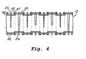
- Fig. 4 shows a front view of sample tube holder 11 in Fig. 1 in the direction of arrow 18 in Fig. 1.
- Fig. 4 shows that the garter springs 31, 33 respectively 32, 34 of adjacent chambers 13 are not located at the same heights, but are located at heights which are offset with respect to each other. This feature allows a more compact arrangement of the chambers of the sample tube holder 11.
- the arrangement of the garter springs 31 and 33, respectively 32, 34 shown in Fig. 1 also contributes to arrange chambers 13 close to each other and thereby achieve a compact arrangement of the chambers of the sample tube holder 11.
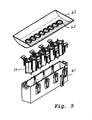
- FIG. 5 shows an exploded perspective view of the above described sample tube holder 11 and of components used for installing it in a clinical chemistry analyzer.
- Figure 5 shows a frame 61 for receiving solid body 12 of sample tube holder 11. Frame 61 is inserted into and connected to a suitable cavity of the analyzer.
- Figure 5 also shows a cover 62 with openings 63 which spatially correspond to the upper openings 15 of the chambers 13 of solid body 12. Cover 61 accurately fits into a corresponding opening of a cover plate (not shown) of the analyzer.
- Fig. 6 shows a sample tube holder assembly 64 of the components shown by Fig.5.
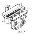
- Fig. 7 shows the assembly 64 of Fig. 6 after is installed in a supporting frame 65 which is part of the analyzer.
- Fig. 8 shows a cross-sectional view of sample tube holder assembly 64 in Fig. 6 and of sample tubes 21 and 22 inserted in respective chambers 13 of sample tube holder 11 along a plane passing through the length symmetry axis of all chambers 13 of sample tube holder 11.
- Fig. 8 shows the length symmetry axis of one of chambers 13 of sample tube holder 11 and the length symmetry axis 23 of one of sample tubes 21 a longitudinal portion of which is inserted in one of the chambers 13 of sample tube holder 11.
- a longitudinal portion of a first sample tube 21 having a first diameter is inserted in a first chamber 13 of sample tube holder 11 and sample tube is centered and held in place in chamber 13 by garter springs 31 and 32.
- a longitudinal portion of a second sample tube 22 having a second diameter smaller than the diameter of sample tube 21 is inserted in a second chamber 13 of sample tube holder 11.
- Sample tube 22 is shorter than sample tube 21 and also shorter than the length of chamber 13.
- the upper part of sample tube 22 has an annular flange which fits on the upper rim of an opening 63 (see Fig. 5) of cover 62 when the lower portion of sample tube 22 is inserted into a chamber 13.
- Sample tube 22 is centered and held in place in second chamber 13 on the one hand by the fitting of flange 24 on the upper rim of opening 63 and on the other hand by garter spring 33 which holds the central part of sample tube 22.
- Fig. 9 shows a perspective view of an analyzer comprising a sample tube holder according to the invention, e.g. a clinical-chemistry analyzer for analyzing sample-reagent mixtures formed by mixing aliquots of biological samples taken from primary sample tubes and reagents contained in reagent containers.
- a sample tube holder 11 according to the invention is part of a sample tube holder assembly 64 and is installed in a sample tube area 69 located adjacent to a conveyor 66 for conveying reaction cuvettes 67 inserted in corresponding cavities of conveyor 66 along a circular path.
- a removable reagent container assembly 68 containing a plurality of reagent containers is installed in the central part of conveyor 66.
- the analyzer shown by Fig. 9 further comprises an automatic pipetting unit 71, a photometer located adjacent to conveyor and conveyor driving means for rotating conveyor.
- Automatic pipetting unit 71 is suitable for effecting all pipetting operations in the analyzer, e.g. the pipetting of a sample portion taken from a sample tube held by the sample tube holder in sample area 69 into a reaction cuvette 67 in conveyor 66 and the pipetting of a reagent volume taken from a reagent container in reagent container assembly 68 into a reaction cuvette 67 in conveyor 66. After these pipetting operations the reaction cuvette 67 contains a sample-reagent-mixture.
- Automatic pipetting unit 71 comprises a removably mounted pipetting needle 72 and a transport device 74 mounted on a rail 73 which extends in the X-direction shown in Fig. 5.
- This transport device 74 moves the pipetting needle 72 along a rectilinear path in the X-direction for bringing pipetting needle 72 to several pipetting positions, in a particular a pipetting position in the sample tube area 69 for taking an aliquot of a sample to be analyzed, another pipetting position for taking an aliquot of a reagent from a reagent container and another pipetting position for delivering the sample and reagent aliquots into a reaction cuvette 67 installed in the conveyor 66.
- Automatic pipetting unit 71 comprises a needle transport head 74 which is moved along rail 73 in Fig. 9 for moving pipetting needle 72 along a straight line in a first direction, e.g. in a direction parallel to the X-axis in Fig. 1, to a plurality of pipetting positions all of which have centers that lie in one and the same vertical plane, e.g. a plane which is parallel to the X-Z-plane in Fig. 1, and which passes through the above mentioned straight line.
- Fig. 10 shows a schematic top plan view of the analyzer of Fig. 9.
- Fig. 10 shows a top plan view of a cover of the analyzer shown by Fig. 9.
- the latter cover has the following openings which allow performing pipetting operations with pipetting needle 72: a first opening 312 for taking a reagent volume from a reagent container, a second opening 313 for taking a reagent volume from another reagent container, a third opening 314 for performing pipetting operations in one of the reaction cuvettes 67 on conveyor 66, a fourth opening 319 for contacting a reference member for performing an initialization method and for accessing washing station and a fifth opening 315 for performing pipetting operations in a chamber of an ISE device.
- the centers of the above mentioned openings in the cover (not shown) of the analyzer shown by Fig. 9 define the location of pipetting positions to which pipetting needle 72 has to be brought to by transport head 74.
- Figure 10 also shows on the right side the sample area 69 and the upper openings 63 of the cover of the sample tube holder assembly 64 which holds sample tubes.
- the centers of the openings 63 are further pipetting positions to which pipetting needle 72 has to be brought to by transport head 74.
Landscapes
- Chemical & Material Sciences (AREA)
- Chemical Kinetics & Catalysis (AREA)
- Health & Medical Sciences (AREA)
- General Health & Medical Sciences (AREA)
- Immunology (AREA)
- Life Sciences & Earth Sciences (AREA)
- Analytical Chemistry (AREA)
- Biochemistry (AREA)
- Clinical Laboratory Science (AREA)
- General Physics & Mathematics (AREA)
- Physics & Mathematics (AREA)
- Pathology (AREA)
- Automatic Analysis And Handling Materials Therefor (AREA)
- Sampling And Sample Adjustment (AREA)
- Devices For Use In Laboratory Experiments (AREA)
- Analysing Materials By The Use Of Radiation (AREA)
- Centrifugal Separators (AREA)
Abstract
A sample tube holder (11) for receiving and holding a plurality of sample tubes (21, 22) having a cylindrical shape and outer diameters lying in a predetermined range, each sample tube having a length symmetry axis (23). The sample tube holder comprises a solid body (12) defining a rectilinear array of elongated chambers (13) and elastic means (31, 32) associated with and located outside of each chamber (13) of the array. These elastic are adapted for centering each sample tube (21, 22) arranged in a chamber so that the length symmetry axis (23) of the sample tube coincides with the length symmetry axis (17) of the chamber (13). The chambers (13) have each the same shape and dimensions. Each chamber has side walls (14), an upper opening (15), a lower opening (16) and a length symmetry axis (17). Each chamber is adapted for receiving a longitudinal portion of a sample tube (21, 22).
Description
- The invention concerns a sample tube holder according to the preamble of claim 1.
- A known sample tube holder used in clinical chemistry analyzer comprises a rectilinear array of chambers, each of which is adapted for receiving and holding in place a sample tube. All chambers of the array have the same shape and dimensions. The length symmetry axis of all chambers of the sample tube holder lie in one and the same plane, e.g. in a symmetry plane of the rectilinear array of chambers of the sample tube holder.
- Primary sample tubes used in clinical chemistry analyzers usually have different diameters and usually also different lengths. In order to hold such primary sample tubes in place, each of the chambers of a known sample tube holder includes an elastic tongue which extends from the inner surface of a side wall of the chamber with an inclination towards the center thereof and which presses each sample tube against a side wall of the chamber. When several sample tubes having different diameters are inserted in respective chambers of such a sample tube holder, the length symmetry axis of the sample tubes are not aligned and lie at different distances from the plane which contains the length symmetry axis of the chambers of the sample tube holder. Sample tubes having a diameter close to the inner diameter of the chambers of the sample tube holder where they are inserted are approximately centered in those chambers, whereas the centers of smaller sample tubes clearly lie out of the centers of the chambers where they are inserted.
- In another known sample tube holder the side walls of each of the chambers of the sample tube holder include four elastic tongues with an angular spacing of 90 degrees between them and these tongues press the sample tube towards the length symmetry axis of the chamber. Although centering of the sample tube can be in principle achieved in this way, in practice however manufacturing tolerances and non-uniform deformation of the tongues with time makes it impossible to ensure that each of the sample tubes inserted in the chambers of the known sample tube holder is accurately centered and that the length symmetry axis of all sample tubes inserted in the sample tube holder are accurately aligned and lie in the symmetry plane of the sample tube holder.
- For the reasons indicated above, the prior art sample tube holders described above are not suitable for use in an analyzer where it is necessary that every one of the sample tubes is accurately centered in a chamber of the sample tube holder and that the length symmetry axis of all sample tubes inserted in the sample tube holder are accurately aligned and lie in the symmetry plane of the sample tube holder. This is for instance required if the sample tube holder is used in an analyzer having an automatic pipetting unit which moves the pipetting needle only along a rectilinear path which lies in the symmetry plane of the array of chambers of the sample tube holder.
- An aim of the invention is to provide a sample tube holder of the above mentioned kind wherein each chamber of the holder includes means for accurately centering sample tubes of different diameters so that the length symmetry axis of each sample tube inserted in a chamber of the sample tube holder coincides with the length symmetry axis of the chamber of the sample tube holder in which the sample tube is positioned, and thereby the length symmetry axis of all sample tubes in the sample holder are aligned and lie in the plane which contains the length symmetry axis of all the chambers of the sample tube holder.
- According to the invention the above aim is achieved by means of a sample tube holder defined by claim 1. Claims 2 to 10 define preferred embodiments of this sample tube holder.
- The main advantages obtained with a sample tube holder according to the invention are that it provides a low cost means for accurately centering each sample tube in the chamber of the sample tube holder where the sample tube is inserted and also contributes to reduce the manufacturing cost of the analyzer by making possible use of a low cost automatic pipetting unit which moves the pipetting needle only along a rectilinear path which lies in the symmetry plane of the array of chambers of the sample tube holder, instead of e.g. a more expensive automatic pipetting unit which moves the pipetting needle in three directions (X, Y, Z) orthogonal to each other.
- The subject invention will now be described in terms of its preferred embodiments with reference to the accompanying drawings. These embodiments are set forth to aid the understanding of the invention, but are not to be construed as limiting.
- Fig. 1
- shows a perspective view of a sample tube holder according to the invention.
- Fig. 2
- shows a top view of a
chamber 13 and agarter spring 31 ofsample tube holder 11 shown in Fig. 1. - Fig. 3
- shows a top view of each of
garter springs - Fig. 4
- shows a front view of
sample tube holder 11 in Fig. 1 in the direction ofarrow 18 in Fig. 1. - Fig. 5
- shows an exploded perspective view of the components of a sample tube holder assembly comprising a
sample tube holder 11 shown in Fig. 1. - Fig. 6
- shows a sample
tube holder assembly 64 of the components shown by Fig. 5. - Fig. 7
- shows the sample
tube holder assembly 64 of Fig. 6 after is installed in a supportingframe 65 which is part of the analyzer. - Fig. 8
- shows a cross-sectional view of sample
tube holder assembly 64 in Fig. 6 and ofsample tubes respective chambers 13 ofsample tube holder 11 along a plane passing through the length symmetry axis of allchambers 13 ofsample tube holder 11. - Fig. 9
- shows a perspective view of an analyzer comprising a sample tube holder according to the invention.
- Fig.10
- shows a schematic top view of the analyzer shown by Fig. 9 and in particular the arrangement of the pipetting openings in a cover of the analyzer.
-
- 11
- sample tube holder
- 12
- solid body
- 13
- chamber of the sample tube holder
- 14
- side walls of
chamber 13 - 15
- upper opening
- 16
- lower opening
- 17
- length symmetry axis of a
chamber 13 - 18
- arrow
- 21
- sample tube
- 22
- sample tube
- 23
- length symmetry axis of a sample tube
- 24
- annular flange
- 31
- garter spring
- 32
- garter spring
- 33
- garter spring
- 34
- garter spring
- 41
- pin
- 42
- pin
- 43
- pin
- 44
- first circle
- 45
- second circle
- 46
- circle / inner surface of
side wall 14 ofchamber 13 - 51
- pin
- 52
- pin
- 53
- pin
- 61
- frame
- 62
- cover
- 63
- openings
- 64
- sample tube holder assembly
- 65
- supporting frame
- 66
- conveyor
- 67
- reaction cuvette
- 68
- reagent container assembly
- 69
- sample tube area
- 71
- automatic pipetting device
- 72
- pipetting needle
- 73
- rail of transport device of pipetting needle
- 74
- transport head for transporting
pipetting needle 72 - 312
- first opening for pipetting reagents
- 313
- second opening for pipetting reagents
- 314
- opening for pipetting into a reaction cuvette
- 315
- opening for pipetting into chamber of an ISE device
- 319
- opening giving access to reference member
- 320
- pipetting axis
- Preferred embodiments of a sample tube holder according to the invention are described hereinafter with reference to Figures 1 to 10. Such a sample tube holder is adapted for receiving and holding a plurality of
sample tubes 21 having a cylindrical shape and outer diameters lying in a predetermined range, e.g. in a range going from about 11 to about 16 millimeter. Each ofsample tubes 21 has alength symmetry axis 23. - As shown by Fig. 1 a sample tube holder according to the invention comprises a
solid body 12 defining a rectilinear array ofelongated chambers 13 andelastic means chamber 13 of the array. -
Solid body 12 is preferably made by injection molding of a suitable a plastic material. - Elastic means 31 and 32 are adapted for centering each
sample tube 21 arranged in a chamber so that thelength symmetry axis 23 of the sample tube coincides with thelength symmetry axis 17 of thechamber 13.Chambers 13 have each the same shape and dimensions. Eachchamber 13 hasside walls 14, anupper opening 15, a lower opening 16 and alength symmetry axis 17. Eachchamber 13 is adapted for receiving a longitudinal portion of asample tube 21. - In a preferred embodiment shown by Fig. 1,
solid body 12 comprises for each of chambers 13 a first array of pins, e.g. pins 41, 42, 43 in Fig. 1, which are e.g. longitudinal projections of theside walls 14 ofchamber 13 and extend upwards, and a second array of pins, e.g. pins 51, 52, 53 in Fig. 1, which are e.g. longitudinal projections of theside walls 14 ofchamber 13 and extend downwards. In this embodiment the elastic means associated with eachchamber 13 comprise afirst garter spring 31 stretched around the first array of pins and asecond garter spring 32 stretched around the second array of pins. Garter springs 31, 32 are thus arranged with some pre-stressing around the above mentioned first and second array of pins respectively. - In the above described configuration garter springs 31 and 32 are stretched around the first respectively the second array of pins and exert equal radial forces on angularly equidistant points of the outer surface of a sample tube inserted in a
chamber 13. Connecting the ends of a garter spring can be accomplished in several ways; interlocking the end loops, tapering one end and screwing into the opposite end, soldering, or using another short extension spring as a connector by screwing it into both ends of the spring body. - Fig. 3 shows a top view of each of garter springs 31 and 32 in their resting states. As shown by Fig. 3,
garter spring 31 respectively 32 is a thin coil spring with ends joined to form a ring. Garter springs 31, 32 are made of stainless steel and each of them has a body which has preferably a width W lying in a range going from about 1.5 to about 2.0 millimeter. - In a preferred embodiment, the pins of the first array of pins as well as the pins of the second array of pins are located at the corners of a regular polygon.
- In a preferred embodiment the corners of the regular polygon lie on a first circle in a plane normal to the
length symmetry axis 17 ofchamber 13, the center of the first circle lies on thelength symmetry axis 17 ofchamber 13, and the first circle has a surface which is larger than the cross-section ofchamber 13. - In a preferred embodiment the diameter of a second circle inscribed in the regular polygon is smaller than the smallest outer diameter of a
sample tube 21 to be inserted in achamber 13 of the sample tube holder. - In a preferred embodiment the above mentioned regular polygon is an equilateral triangle as shown in Figures 1, 2 and 5.
- As shown by Fig. 2
garter spring 31 is stretched along a path which has the shape of an equilateral triangle. This also applies to garter spring 32 (not shown by Fig. 2) - In the preferred embodiment shown by Fig. 2 the centers of
pins pins circle 44 in a plane normal to thelength symmetry axis 17 ofchamber 13, the center ofcircle 44 lies on thelength symmetry axis 17 ofchamber 13. - Each of the above mentioned pins has a cylindrical shape and a diameter of e.g. 2 millimeter.
- Fig. 2 also shows
side wall 14 ofchamber 13 and acircle 46 which represents the inner surface ofside wall 14 ofchamber 13. The diameter ofcircle 46 determines the maximum diameter a sample tube insertable inchamber 13 may have. In the embodiment described above with reference to Fig. 2circle 46 has a diameter of 16.3 millimeter and the largest diameter of a sample tube insertable in achamber 13 of that embodiment is 16.2 millimeter. - As shown by Fig. 2,
circle 44 has a surface which is larger than the cross-section ofchamber 13 defined by the surface ofcircle 46. - As shown by Fig. 2, the inner sides of
garter spring 31 extend along the sides of an equilateral triangle. Fig. 2 shows acircle 45 inscribed in the latter triangle. Asample tube holder 11 according to the invention is suitable for holding sample tubes having an outer diameter that is larger than the diameter ofcircle 45. In other words the diameter ofcircle 45 is smaller than the smallest outer diameter of asample tube 21 to be inserted in achamber 13 ofsample tube holder 11. - Fig. 3 shows the shape of each of garter springs 31 and 32 in their resting states. As shown by Fig. 3, each of this springs has an inner diameter D1, an outer diameter D2 and a width W. The latter inner diameter D1 is smaller than the diameter of
circle 44 in Fig. 2. - In the embodiment described above with reference to Fig. 2, garter springs 31 and 32 have a width W of e.g. 1.65 millimeter.
- Fig. 4 shows a front view of
sample tube holder 11 in Fig. 1 in the direction ofarrow 18 in Fig. 1. Fig. 4 shows that the garter springs 31, 33 respectively 32, 34 ofadjacent chambers 13 are not located at the same heights, but are located at heights which are offset with respect to each other. This feature allows a more compact arrangement of the chambers of thesample tube holder 11. The arrangement of the garter springs 31 and 33, respectively 32, 34 shown in Fig. 1 also contributes to arrangechambers 13 close to each other and thereby achieve a compact arrangement of the chambers of thesample tube holder 11. - Fig. 5 shows an exploded perspective view of the above described
sample tube holder 11 and of components used for installing it in a clinical chemistry analyzer. Figure 5 shows aframe 61 for receivingsolid body 12 ofsample tube holder 11.Frame 61 is inserted into and connected to a suitable cavity of the analyzer. Figure 5 also shows acover 62 withopenings 63 which spatially correspond to theupper openings 15 of thechambers 13 ofsolid body 12.Cover 61 accurately fits into a corresponding opening of a cover plate (not shown) of the analyzer. - Fig. 6 shows a sample
tube holder assembly 64 of the components shown by Fig.5. - Fig. 7 shows the
assembly 64 of Fig. 6 after is installed in a supportingframe 65 which is part of the analyzer. - Fig. 8 shows a cross-sectional view of sample
tube holder assembly 64 in Fig. 6 and ofsample tubes respective chambers 13 ofsample tube holder 11 along a plane passing through the length symmetry axis of allchambers 13 ofsample tube holder 11. Fig. 8 shows the length symmetry axis of one ofchambers 13 ofsample tube holder 11 and thelength symmetry axis 23 of one of sample tubes 21 a longitudinal portion of which is inserted in one of thechambers 13 ofsample tube holder 11. - In Fig. 8, a longitudinal portion of a
first sample tube 21 having a first diameter is inserted in afirst chamber 13 ofsample tube holder 11 and sample tube is centered and held in place inchamber 13 by garter springs 31 and 32. - In Fig. 8, a longitudinal portion of a
second sample tube 22 having a second diameter smaller than the diameter ofsample tube 21 is inserted in asecond chamber 13 ofsample tube holder 11.Sample tube 22 is shorter thansample tube 21 and also shorter than the length ofchamber 13. The upper part ofsample tube 22 has an annular flange which fits on the upper rim of an opening 63 (see Fig. 5) ofcover 62 when the lower portion ofsample tube 22 is inserted into achamber 13.Sample tube 22 is centered and held in place insecond chamber 13 on the one hand by the fitting offlange 24 on the upper rim of opening 63 and on the other hand bygarter spring 33 which holds the central part ofsample tube 22. - Fig. 9 shows a perspective view of an analyzer comprising a sample tube holder according to the invention, e.g. a clinical-chemistry analyzer for analyzing sample-reagent mixtures formed by mixing aliquots of biological samples taken from primary sample tubes and reagents contained in reagent containers. A
sample tube holder 11 according to the invention is part of a sampletube holder assembly 64 and is installed in asample tube area 69 located adjacent to aconveyor 66 for conveying reaction cuvettes 67 inserted in corresponding cavities ofconveyor 66 along a circular path. A removablereagent container assembly 68 containing a plurality of reagent containers is installed in the central part ofconveyor 66. The analyzer shown by Fig. 9 further comprises anautomatic pipetting unit 71, a photometer located adjacent to conveyor and conveyor driving means for rotating conveyor. -
Automatic pipetting unit 71 is suitable for effecting all pipetting operations in the analyzer, e.g. the pipetting of a sample portion taken from a sample tube held by the sample tube holder insample area 69 into a reaction cuvette 67 inconveyor 66 and the pipetting of a reagent volume taken from a reagent container inreagent container assembly 68 into a reaction cuvette 67 inconveyor 66. After these pipetting operations the reaction cuvette 67 contains a sample-reagent-mixture. -
Automatic pipetting unit 71 comprises a removably mountedpipetting needle 72 and atransport device 74 mounted on arail 73 which extends in the X-direction shown in Fig. 5. Thistransport device 74 moves thepipetting needle 72 along a rectilinear path in the X-direction for bringingpipetting needle 72 to several pipetting positions, in a particular a pipetting position in thesample tube area 69 for taking an aliquot of a sample to be analyzed, another pipetting position for taking an aliquot of a reagent from a reagent container and another pipetting position for delivering the sample and reagent aliquots into a reaction cuvette 67 installed in theconveyor 66. -
Automatic pipetting unit 71 comprises aneedle transport head 74 which is moved alongrail 73 in Fig. 9 for movingpipetting needle 72 along a straight line in a first direction, e.g. in a direction parallel to the X-axis in Fig. 1, to a plurality of pipetting positions all of which have centers that lie in one and the same vertical plane, e.g. a plane which is parallel to the X-Z-plane in Fig. 1, and which passes through the above mentioned straight line. - The location of the above-mentioned pipetting positions is illustrated by Fig. 10 which shows a schematic top plan view of the analyzer of Fig. 9. Fig. 10 shows a top plan view of a cover of the analyzer shown by Fig. 9. The latter cover has the following openings which allow performing pipetting operations with pipetting needle 72: a
first opening 312 for taking a reagent volume from a reagent container, asecond opening 313 for taking a reagent volume from another reagent container, athird opening 314 for performing pipetting operations in one of the reaction cuvettes 67 onconveyor 66, afourth opening 319 for contacting a reference member for performing an initialization method and for accessing washing station and afifth opening 315 for performing pipetting operations in a chamber of an ISE device. - The centers of the above mentioned openings in the cover (not shown) of the analyzer shown by Fig. 9 define the location of pipetting positions to which pipetting
needle 72 has to be brought to bytransport head 74. - Figure 10 also shows on the right side the
sample area 69 and theupper openings 63 of the cover of the sampletube holder assembly 64 which holds sample tubes. The centers of theopenings 63 are further pipetting positions to which pipettingneedle 72 has to be brought to bytransport head 74. - As shown by Figures 9 and 10 all above-mentioned pipetting positions have centers which lie in one and the same vertical plane, which is parallel to the X-Z-plane and which passes through the straight line in X-direction along which pipetting
needle 72 is moved bytransport head 74. In Fig. 10 the plane where all the centers of the pipetting positions lie is represented by straight line which is called pipetting axis 320 for the purpose of this description. - Although preferred embodiments of the invention have been described using specific terms, such description is for illustrative purposes only, and it is to be understood that changes and variations may be made without departing from the spirit or scope of the following claims.
Claims (10)
- A sample tube holder (11) for receiving and holding a plurality of sample tubes (21, 22) having a cylindrical shape and outer diameters lying in a predetermined range, each sample tube having a length symmetry axis (23), said sample tube holder comprising(a) a solid body (12) comprising a rectilinear array of elongated chambers (13) having each the same shape and dimensions, each chamber having side walls (14), an upper opening (15), a lower opening (16) and a length symmetry axis (17), and each chamber being adapted for receiving a longitudinal portion of a sample tube (21, 22), and(b) elastic means (31, 32, 33, 34) associated with and located outside of each chamber (13) of said array, said elastic means being adapted for centering each sample tube (21, 22) arranged in said chamber so that the length symmetry axis (23) of said sample tube coincides with the length symmetry axis (17) of said chamber (13).
- A sample tube holder according to claim 1, wherein said solid body (12) is made of a plastic material.
- A sample tube holder according to any of the preceding claims, wherein each of said chambers (13) is adapted for receiving a sample tube (21, 22) having an outer diameter lying in a range going from about 11 to about 16 millimeter.
- A sample tube holder according to any of the preceding claims,
wherein said solid body (12) comprises for each of said chambers (13) a first array of pins (41, 42, 43) which are longitudinal projections of the side walls (14) of said chamber (13) and extend upwards, and a second array of pins (51, 52, 53) which are longitudinal projections of the side walls (14) of said chamber (13) and extend downwards, and
wherein said elastic means comprise a first garter spring (31, 33) stretched around said first array of pins (41, 42, 43) and a second garter spring (32, 34) stretched around said second array of pins (51, 52, 53). - A sample tube holder according to claim 4, wherein each of said first and second garter springs (31, 32, , 33, 34) is made of stainless steel and has a body having a width lying in a range going from about 1.5 to about 2.0 millimeter.
- A sample tube holder according to claim 4, wherein the center of each of said pins (41, 42, 43) of said first array of pins as well as the center of each of said pins (51, 52, 53) of said second array of pins are located at the corners of a regular polygon.
- A sample tube holder according to claim 6, wherein said corners lie on a first circle (44) in a plane normal to the length symmetry axis (17) of said chamber (13), the center of said first circle (44) lying on said the length symmetry axis (17) of said chamber (13), said first circle (44) having a surface which is larger than the cross-section of said chamber (13).
- A sample tube holder according to claim 6, wherein the diameter of a second circle (45) inscribed in said regular polygon is smaller than the smallest outer diameter of a sample tube (21, 22) to be inserted in a chamber (13) of the sample tube holder.
- A sample tube holder according to claim 7, wherein said first garter spring (31, 33) and said second garter spring (32, 34) in their resting state extend each along a third circle having a diameter which is smaller than the diameter of said first circle.
- A sample tube holder according to any of claims 6 to 9, wherein said regular polygon is an equilateral triangle.
Priority Applications (9)
| Application Number | Priority Date | Filing Date | Title |
|---|---|---|---|
| EP05077994A EP1803499A1 (en) | 2005-12-27 | 2005-12-27 | Sample tube holder |
| EP06026161A EP1803500B1 (en) | 2005-12-27 | 2006-12-18 | Sample tube holder |
| AT06026161T ATE481170T1 (en) | 2005-12-27 | 2006-12-18 | SAMPLE TUBE CONTAINER |
| DE602006016909T DE602006016909D1 (en) | 2005-12-27 | 2006-12-18 | Sample tube bucket |
| US11/643,639 US8147777B2 (en) | 2005-12-27 | 2006-12-21 | Sample tube holder |
| CA2572036A CA2572036C (en) | 2005-12-27 | 2006-12-22 | Sample tube holder |
| JP2006350609A JP4740105B2 (en) | 2005-12-27 | 2006-12-26 | Sample tube holder |
| CN2006100642225A CN1991328B (en) | 2005-12-27 | 2006-12-27 | Sample tube holder |
| HK07111138.3A HK1105913B (en) | 2005-12-27 | 2007-10-16 | Sample tube holder |
Applications Claiming Priority (1)
| Application Number | Priority Date | Filing Date | Title |
|---|---|---|---|
| EP05077994A EP1803499A1 (en) | 2005-12-27 | 2005-12-27 | Sample tube holder |
Publications (1)
| Publication Number | Publication Date |
|---|---|
| EP1803499A1 true EP1803499A1 (en) | 2007-07-04 |
Family
ID=35929855
Family Applications (2)
| Application Number | Title | Priority Date | Filing Date |
|---|---|---|---|
| EP05077994A Withdrawn EP1803499A1 (en) | 2005-12-27 | 2005-12-27 | Sample tube holder |
| EP06026161A Active EP1803500B1 (en) | 2005-12-27 | 2006-12-18 | Sample tube holder |
Family Applications After (1)
| Application Number | Title | Priority Date | Filing Date |
|---|---|---|---|
| EP06026161A Active EP1803500B1 (en) | 2005-12-27 | 2006-12-18 | Sample tube holder |
Country Status (7)
| Country | Link |
|---|---|
| US (1) | US8147777B2 (en) |
| EP (2) | EP1803499A1 (en) |
| JP (1) | JP4740105B2 (en) |
| CN (1) | CN1991328B (en) |
| AT (1) | ATE481170T1 (en) |
| CA (1) | CA2572036C (en) |
| DE (1) | DE602006016909D1 (en) |
Cited By (4)
| Publication number | Priority date | Publication date | Assignee | Title |
|---|---|---|---|---|
| EP2327989A4 (en) * | 2008-09-24 | 2016-04-20 | Hitachi High Tech Corp | SAMPLE CARRIER |
| CN107081180A (en) * | 2017-05-31 | 2017-08-22 | 张云生 | A kind of support of blood collecting pipe and its application method |
| WO2017151774A1 (en) * | 2016-03-02 | 2017-09-08 | Becton, Dickinson And Company | Packaging and devices to access screw-top containers in automated systems |
| CN107243369A (en) * | 2017-05-31 | 2017-10-13 | 张云生 | A kind of adjustable support of blood collecting pipe and its application method |
Families Citing this family (20)
| Publication number | Priority date | Publication date | Assignee | Title |
|---|---|---|---|---|
| US20110086778A1 (en) * | 2009-10-13 | 2011-04-14 | Herrmann Mark G | Enhanced microplate configurations |
| US20110152128A1 (en) * | 2009-10-13 | 2011-06-23 | Herrmann Mark G | Enhanced microplate configurations |
| JP2011230096A (en) * | 2010-04-30 | 2011-11-17 | Atect Corp | Supporting tool of sample tube |
| CN107831324B (en) | 2013-03-15 | 2021-11-19 | 雅培制药有限公司 | Automated diagnostic analyzer with rear accessible track system and related methods |
| CN105190317B (en) | 2013-03-15 | 2018-05-04 | 雅培制药有限公司 | Diagnostic analysis machine with preprocessing carousel and related method |
| CN105378487B (en) | 2013-03-15 | 2018-08-21 | 雅培制药有限公司 | Automated diagnostic analyzer with vertically arranged carousel and related method |
| SE538287C2 (en) * | 2013-09-30 | 2016-04-26 | Symcel Sverige AB | Sample holder adapted to isothermal calorimetry of parallel samples |
| GB201319759D0 (en) * | 2013-11-08 | 2013-12-25 | Thomsen Lars | Device and method for heating a fluid chamber |
| USD837401S1 (en) | 2016-03-22 | 2019-01-01 | Abbott Laboratories | Carrier for use in a diagnostic analyzer |
| CN110914672A (en) | 2017-04-20 | 2020-03-24 | 生物梅里埃公司 | Optical test platform |
| EP3621740B1 (en) | 2017-05-12 | 2021-07-21 | Thermo Fisher Scientific Oy | Receptacle holder and receptacle rack |
| SE542103C2 (en) * | 2017-11-09 | 2020-02-25 | Hemocue Ab | A microcuvette holder, an analysis apparatus comprising the holder and method for analysing a blood sample using the analysis apparatus |
| EP4219014A1 (en) | 2018-01-23 | 2023-08-02 | F. Hoffmann-La Roche AG | Tube tray for secondary tubes and secondary tube handling module |
| AU2019398123B2 (en) * | 2018-12-14 | 2023-10-12 | Becton, Dickinson And Company | Rack for sample tubes |
| US11083295B2 (en) * | 2019-04-02 | 2021-08-10 | DePuy Synthes Products, Inc. | Tube rack apparatus |
| USD937435S1 (en) | 2019-05-07 | 2021-11-30 | Abbott Laboratories | Carrier for use in a diagnostic analyzer |
| JP7332143B2 (en) * | 2019-06-12 | 2023-08-23 | 阪神容器株式会社 | Reagent container manufacturing method |
| WO2022176309A1 (en) * | 2021-02-19 | 2022-08-25 | 株式会社日立ハイテク | Container holder, analysis device, and method for manufacturing container holder |
| CN113893902B (en) * | 2021-10-29 | 2024-03-12 | 济南迪安医学检验中心有限公司 | Clinical laboratory uses test tube storage device |
| CN115791359A (en) * | 2022-11-18 | 2023-03-14 | 中国航发哈尔滨轴承有限公司 | Heat treatment bearing frame for test sample for testing tensile and impact properties |
Citations (4)
| Publication number | Priority date | Publication date | Assignee | Title |
|---|---|---|---|---|
| US5080232A (en) * | 1989-06-01 | 1992-01-14 | Nalge Company | Test tube rack and retainer |
| US5651941A (en) * | 1992-06-29 | 1997-07-29 | Dade International Inc. | Sample tube carrier |
| US20040195193A1 (en) * | 2003-04-03 | 2004-10-07 | Bio-Rad Laboratories, Inc. | Tube rack accommodating a range of tube diameters |
| US20050180896A1 (en) * | 2004-02-17 | 2005-08-18 | Ids Company, Ltd. | Test tube holder |
Family Cites Families (8)
| Publication number | Priority date | Publication date | Assignee | Title |
|---|---|---|---|---|
| US2593794A (en) * | 1947-07-22 | 1952-04-22 | Resina Automatic Machinery Co | Rotatable cap applying chuck with cap gripping helical spring |
| US3142385A (en) * | 1961-09-07 | 1964-07-28 | James F Kahlenberg | Culture tube holder |
| US3352427A (en) * | 1965-08-12 | 1967-11-14 | Wallace C Lawrence | Volumetric flask rack |
| US3819194A (en) * | 1972-10-16 | 1974-06-25 | Domain Ind Inc | Tube holder |
| US5137693A (en) * | 1990-07-30 | 1992-08-11 | Miles Inc. | Spring biased test tube holder |
| JPH0910605A (en) | 1995-06-30 | 1997-01-14 | Suzuki Motor Corp | Test tube support rack |
| JP3729807B2 (en) * | 2002-12-26 | 2005-12-21 | 照明 伊藤 | Sample transport holder transfer system |
| JP2005233664A (en) * | 2004-02-17 | 2005-09-02 | Ids:Kk | Test tube rack |
-
2005
- 2005-12-27 EP EP05077994A patent/EP1803499A1/en not_active Withdrawn
-
2006
- 2006-12-18 EP EP06026161A patent/EP1803500B1/en active Active
- 2006-12-18 DE DE602006016909T patent/DE602006016909D1/en active Active
- 2006-12-18 AT AT06026161T patent/ATE481170T1/en not_active IP Right Cessation
- 2006-12-21 US US11/643,639 patent/US8147777B2/en active Active
- 2006-12-22 CA CA2572036A patent/CA2572036C/en not_active Expired - Fee Related
- 2006-12-26 JP JP2006350609A patent/JP4740105B2/en not_active Expired - Fee Related
- 2006-12-27 CN CN2006100642225A patent/CN1991328B/en not_active Expired - Fee Related
Patent Citations (4)
| Publication number | Priority date | Publication date | Assignee | Title |
|---|---|---|---|---|
| US5080232A (en) * | 1989-06-01 | 1992-01-14 | Nalge Company | Test tube rack and retainer |
| US5651941A (en) * | 1992-06-29 | 1997-07-29 | Dade International Inc. | Sample tube carrier |
| US20040195193A1 (en) * | 2003-04-03 | 2004-10-07 | Bio-Rad Laboratories, Inc. | Tube rack accommodating a range of tube diameters |
| US20050180896A1 (en) * | 2004-02-17 | 2005-08-18 | Ids Company, Ltd. | Test tube holder |
Cited By (8)
| Publication number | Priority date | Publication date | Assignee | Title |
|---|---|---|---|---|
| EP2327989A4 (en) * | 2008-09-24 | 2016-04-20 | Hitachi High Tech Corp | SAMPLE CARRIER |
| WO2017151774A1 (en) * | 2016-03-02 | 2017-09-08 | Becton, Dickinson And Company | Packaging and devices to access screw-top containers in automated systems |
| CN109071081A (en) * | 2016-03-02 | 2018-12-21 | 贝克顿·迪金森公司 | Into the packaging and equipment of the container with screw lid in automated system |
| US11607204B2 (en) | 2016-03-02 | 2023-03-21 | Becton Dickinson And Company | Packaging and devices to access screw-top containers in automated systems |
| CN107081180A (en) * | 2017-05-31 | 2017-08-22 | 张云生 | A kind of support of blood collecting pipe and its application method |
| CN107243369A (en) * | 2017-05-31 | 2017-10-13 | 张云生 | A kind of adjustable support of blood collecting pipe and its application method |
| CN107081180B (en) * | 2017-05-31 | 2019-03-08 | 温州智权工业设计有限公司 | A kind of support of blood collecting pipe and its application method |
| CN107243369B (en) * | 2017-05-31 | 2019-03-08 | 温州智权工业设计有限公司 | A kind of adjustable support of blood collecting pipe and its application method |
Also Published As
| Publication number | Publication date |
|---|---|
| EP1803500A1 (en) | 2007-07-04 |
| CA2572036C (en) | 2010-03-30 |
| JP4740105B2 (en) | 2011-08-03 |
| US20080025878A1 (en) | 2008-01-31 |
| US8147777B2 (en) | 2012-04-03 |
| CA2572036A1 (en) | 2007-06-27 |
| JP2007178435A (en) | 2007-07-12 |
| CN1991328A (en) | 2007-07-04 |
| HK1105913A1 (en) | 2008-02-29 |
| ATE481170T1 (en) | 2010-10-15 |
| DE602006016909D1 (en) | 2010-10-28 |
| CN1991328B (en) | 2013-01-16 |
| EP1803500B1 (en) | 2010-09-15 |
Similar Documents
| Publication | Publication Date | Title |
|---|---|---|
| CA2572036C (en) | Sample tube holder | |
| EP1465728B1 (en) | Stackable aliquot vessel array | |
| US6063341A (en) | Disposable process device | |
| US9079178B2 (en) | Apparatus and methods for pipetting with interchangeability among different pipette tips | |
| CA2067425C (en) | Cuvette for optical measurements | |
| US20140050619A1 (en) | Reaction Vessel | |
| EP2327989A1 (en) | Specimen rack | |
| AU2001297904A1 (en) | Plate locator for precision liquid handler | |
| US5738827A (en) | Apparatus for holding reagent and sample vessels | |
| CA2560211C (en) | Reagent container assembly and analyzer comprising such assembly | |
| CN1936587B (en) | Cuvette holder, cuvette array and analyzer comprising such components | |
| WO2020066165A1 (en) | Reaction vessel for automated analyzer | |
| US12123815B2 (en) | Solid phase microextraction device, repository, and manipulator | |
| AU2002335887B2 (en) | Sample well strip | |
| US4567021A (en) | U-Shaped reaction tube made of elastic material | |
| US20090263290A1 (en) | Capillary storage and dispensing container | |
| EP0752100A1 (en) | Reagent segment | |
| HK1105913B (en) | Sample tube holder | |
| CN117225492A (en) | Method of operating a pipetting system, tool and computer-implemented method | |
| WO2022235612A1 (en) | Taylor cone emitter device respository, taylor cone emitter device respository system, and method for analyzing a population of samples | |
| US20260084158A1 (en) | Device for holding sample vessels and a kit comprising the device | |
| AU686928C (en) | Reagent segment | |
| CN116660567A (en) | Reaction turntable unit, incubation disk device and photochemiluminescence detector |
Legal Events
| Date | Code | Title | Description |
|---|---|---|---|
| PUAI | Public reference made under article 153(3) epc to a published international application that has entered the european phase |
Free format text: ORIGINAL CODE: 0009012 |
|
| AK | Designated contracting states |
Kind code of ref document: A1 Designated state(s): AT BE BG CH CY CZ DE DK EE ES FI FR GB GR HU IE IS IT LI LT LU LV MC NL PL PT RO SE SI SK TR |
|
| AX | Request for extension of the european patent |
Extension state: AL BA HR MK YU |
|
| AKX | Designation fees paid | ||
| REG | Reference to a national code |
Ref country code: DE Ref legal event code: 8566 |
|
| STAA | Information on the status of an ep patent application or granted ep patent |
Free format text: STATUS: THE APPLICATION IS DEEMED TO BE WITHDRAWN |
|
| 18D | Application deemed to be withdrawn |
Effective date: 20080105 |