EP1803403A2 - Ultrasound diagnostic system and method of detecting a lesion - Google Patents
Ultrasound diagnostic system and method of detecting a lesion Download PDFInfo
- Publication number
- EP1803403A2 EP1803403A2 EP06026933A EP06026933A EP1803403A2 EP 1803403 A2 EP1803403 A2 EP 1803403A2 EP 06026933 A EP06026933 A EP 06026933A EP 06026933 A EP06026933 A EP 06026933A EP 1803403 A2 EP1803403 A2 EP 1803403A2
- Authority
- EP
- European Patent Office
- Prior art keywords
- lesion
- center frequency
- ultrasound
- frequency shift
- receive signals
- Prior art date
- Legal status (The legal status is an assumption and is not a legal conclusion. Google has not performed a legal analysis and makes no representation as to the accuracy of the status listed.)
- Granted
Links
Images


Classifications
-
- A—HUMAN NECESSITIES
- A61—MEDICAL OR VETERINARY SCIENCE; HYGIENE
- A61B—DIAGNOSIS; SURGERY; IDENTIFICATION
- A61B8/00—Diagnosis using ultrasonic, sonic or infrasonic waves
-
- G—PHYSICS
- G01—MEASURING; TESTING
- G01S—RADIO DIRECTION-FINDING; RADIO NAVIGATION; DETERMINING DISTANCE OR VELOCITY BY USE OF RADIO WAVES; LOCATING OR PRESENCE-DETECTING BY USE OF THE REFLECTION OR RERADIATION OF RADIO WAVES; ANALOGOUS ARRANGEMENTS USING OTHER WAVES
- G01S7/00—Details of systems according to groups G01S13/00, G01S15/00, G01S17/00
- G01S7/52—Details of systems according to groups G01S13/00, G01S15/00, G01S17/00 of systems according to group G01S15/00
- G01S7/52017—Details of systems according to groups G01S13/00, G01S15/00, G01S17/00 of systems according to group G01S15/00 particularly adapted to short-range imaging
- G01S7/52023—Details of receivers
- G01S7/52036—Details of receivers using analysis of echo signal for target characterisation
- G01S7/52038—Details of receivers using analysis of echo signal for target characterisation involving non-linear properties of the propagation medium or of the reflective target
-
- A—HUMAN NECESSITIES
- A61—MEDICAL OR VETERINARY SCIENCE; HYGIENE
- A61B—DIAGNOSIS; SURGERY; IDENTIFICATION
- A61B8/00—Diagnosis using ultrasonic, sonic or infrasonic waves
- A61B8/48—Diagnostic techniques
- A61B8/481—Diagnostic techniques involving the use of contrast agents, e.g. microbubbles introduced into the bloodstream
-
- G—PHYSICS
- G01—MEASURING; TESTING
- G01S—RADIO DIRECTION-FINDING; RADIO NAVIGATION; DETERMINING DISTANCE OR VELOCITY BY USE OF RADIO WAVES; LOCATING OR PRESENCE-DETECTING BY USE OF THE REFLECTION OR RERADIATION OF RADIO WAVES; ANALOGOUS ARRANGEMENTS USING OTHER WAVES
- G01S15/00—Systems using the reflection or reradiation of acoustic waves, e.g. sonar systems
- G01S15/88—Sonar systems specially adapted for specific applications
- G01S15/89—Sonar systems specially adapted for specific applications for mapping or imaging
- G01S15/8906—Short-range imaging systems; Acoustic microscope systems using pulse-echo techniques
- G01S15/899—Combination of imaging systems with ancillary equipment
Definitions
- the present invention generally relates to an ultrasound diagnostic system and method, and more particularly to an ultrasound diagnostic system and method for detecting a lesion using high intensity focused ultrasound.
- An ultrasound diagnostic system has become an important and popular diagnostic tool due to its wide range of applications. Specifically, due to its non-invasive and non-destructive nature, the ultrasound diagnostic system has been extensively used in the medical profession. Modem high-performance ultrasound diagnostic systems and techniques are commonly used to produce two or three-dimensional (2D or 3D) diagnostic images of a target object
- the ultrasound diagnostic system generally uses a probe including an array transducer having a plurality of transducer elements to transmit and receive ultrasound signals.
- the ultrasound diagnostic system forms ultrasound images of the internal structures of the target object by electrically exciting the transducer elements to generate ultrasound pulses that travel into the target object.
- the ultrasound pulses produce ultrasound echoes since they are reflected from a discontinuous surface of acoustic impedance of the internal structure, which appears as discontinuities to the propagating ultrasound pulses.
- Various ultrasound echoes return to the array transducer and are converted into electrical signals, which are amplified and processed to produce ultrasound data for forming an image of the internal structure of the target object.
- an ultrasound diagnostic system using a high intensity focused ultrasound (HIFU) to remove a lesion (e.g., malignant tumor) in a body has been known to produce excellent treatment effects in the medical field.
- the lesion is necrotized with heat generated by focusing the high intensity ultrasound onto the lesion so that the lesion can be removed in the body. Since the generated heat may destroy other normal tissues around of the lesion in the body, the treatment should be performed carefully while focusing the ultrasound on the lesion so as not to damage the normal tissues.
- the ultrasound diagnostic system provides an ultrasound image showing the lesion being removed by the HIFU. That is, an operator can observe the process of removing the lesion.
- the HIFU significantly increases temperature of a region on which the HIFU is focused, and the necrosis begins at a focal point of the HIFU. Therefore, it is necessary to avoid focusing the HIFU on the normal tissues and to observe thermal diffusion in real time when the HIFU is injected on the lesion, so as not to damage the normal tissues. However, it is difficult to observe the thermal diffusion in the conventional ultrasound diagnostic system
- the following embodiments describe detecting a lesion based on first receive signals and second receive signals-
- the first receive signals are obtained with ultrasound echo signals from the lesion, which has not undergone a high intensity focused ultrasound (HIFU).
- the second receive signals are obtained with ultrasound echo signals from the lesion, which underwent the HIFU.
- HIFU high intensity focused ultrasound
- FIG. 1 illustrates an ultrasound diagnostic system according to one embodiment of the present invention-
- an ultrasound diagnostic system 100 may include an HIFU probe 110, an HIFU unit 120, an imaging probe 130, a beamformer 140, a signal processing unit 150, an image processor 160 and a display unit 170.
- the ultrasound diagnostic system 100 may include a container (not shown in FIG. 1) for containing a medium.
- the container may be a water tank, a water bag and the like.
- the container is disposed between the HIFU probe 110 and a body (i.e., skin) when the HIFU is injected into a body.
- the HIFU probe 110 may inject the HIFU on a lesion 210 in a body 200.
- the HIFU probe 110 may include a number of elements.
- the HIFU unit 120 may provide the HIFU probe 110 with a high frequency power for generating the HIFU and control the HIFU probe 110 to inject the HIFU toward the lesion 210.
- the HIFU unit 120 may include a power supply, a controller and a driver (not shown in FIG 1).
- the power supply provides the high frequency power to the HIFU probe 110.
- the controller generates driving signals, and the driver drives the HIFU probe 110 according to the control signals outputted from the controller to focus the HIFU onto the lesion 210.
- the imaging probe 130 may transmit ultrasound signals to the lesion 210 in the body 200 along transmit scanlines and receive ultrasound echo signals from the lesion 210.
- the imaging probe 130 may further output receive signals obtained from the ultrasound echo signals for forming an ultrasound image showing the lesion 210.
- the imaging probe 130 may include a number of clements arranged in a form of 1-dimensional or a 2-dimensional array.
- the imaging probe 130 may transmit ultrasound signals to a target object, namely, the lesion 210 in the body 200.
- the imaging probe 130 may receive ultrasound echo signals reflected from the lesion 210 and convert the ultrasound echo signals into the first and second receive signals.
- the beamformer 140 may provide appropriate delays to the ultrasound signals for transmission such that the ultrasound signals outputted from the imaging probe 130 are focused on a focal point Further, the beamformer 140 focuses the receive signals by considering the arrival time of the echo signals at each element in the imaging probe 130.
- the signal processing unit 150 may detect the center frequencies of two receive signals outputted from the imaging probe 130 and calculate the center frequency shift between the two receive signals.
- the signal processing unit 150 may include a spectrum analyzing unit 151, a center frequency detecting unit 152 and a center frequency shift calculating unit 153.
- the spectrum analyzing unit 151 may analyze a first spectrum and a second spectrum to produce spectrum analysis results. The first spectrum and the second spectrum are obtained from the first and the second receive signals.
- the center frequency detecting unit 152 may detect the first and second center frequencies from the analysis results, respectively.
- the center frequency shift calculating unit 153 may calculate the difference between the first and second center frequencies.
- the center frequency shift calculating unit 153 may calculate the shift of the first center frequency of the first receive signals due to the HIFU.
- the center frequency difference namely, the center frequency shift, is a pixel value of each pixel for forming a center frequency shift image.
- the signal processing unit 150 may also determine a position of the lesion in consideration of the center frequency shift.
- the signal processing unit 150 may further include a position determining unit 154.
- the position determining unit 154 may determine a position of the lesion based on the center frequency shift. Specifically, the position determining unit 154 may search a region in which pixels having pixel values within a predetermined range are adjacent to one another based on the fact that the center frequency shift is significant at the boundary of the lesion. The boundary of the region may be adopted to determine the position of the lesion boundary.
- the image processor 160 may form at least one ultrasound image showing the lesion based on the receive signals and a center frequency shift image based on the center frequency shift. Also, the image processor 160 may form an overlap image of the ultrasound image and the center frequency shift image. Thus, the image processor 160 may remove the background of the center frequency shift image to form a transparent center frequency shift image, which shows only the boundary of the lesion, to be overlapped with the ultrasound image. Specifically, in order to form the transparent center frequency shift image, the image processor 160 may set the pixel values of all the pixels outside the region to zero in the center frequency shift image. According to another embodiment, the image processor 160 may express the background of the center frequency shift image with transparency in pseudo color map so as to leave only the boundary of the lesion.
- the display unit 170 may display at least one of the ultrasound image, the center frequency shift image and the overlap image. For example, by dividing a display area of the display unit 170 into a plurality of sub-areas, the ultrasound image, the center frequency shift image and the overlap image may be displayed in each respective sub-areas.
- the imaging probe 130 may transmit first ultrasound signals to a lesion in a body (step S110) and receive first ultrasound echo signals (step S120).
- the spectrum analyzing unit 151 may analyze the first spectrum of the first ultrasound echo signals to produce a first spectrum analysis result (step S130).
- the center frequency detecting unit 152 may detect the first center frequency from the first spectrum based on the first spectrum analysis result (step S140).
- the HIFU probe may inject the HIFU onto the lesion (step S150). Also, the imaging probe 130 may transmit second ultrasound signals to the lesion, which underwent the HIFU (step S160), and receive second ultrasound echo signals (step S170).
- the spectrum analyzing unit 151 may analyze a second spectrum of the second ultrasound echo signals to produce a second spectrum analysis result (step S180).
- the center frequency detecting unit 152 may detect a second center frequency from the second spectrum based on the second spectrum analysis result (step S190).
- the center frequency shift calculating unit 153 may calculate a center frequency shift, that is, a difference between the first and second center frequencies as shown in FIG. 3 (step S200).
- the position determining unit 154 may determine the position of the lesion (i.e.., boundary of the lesion) based on the center frequency shift calculated by the center frequency detecting unit 152 (step S210).
- the center frequency shift is a pixel value of each pixel for forming a center frequency shift image.
- the position determining unit 514 may search a region including pixels of which pixel values are within a predetermined range and adjacent to one another. In such a case, the position determining unit may determine the position of the lesion in consideration of a boundary of the region.
- the image processor 160 may form the center frequency shift image based on the center frequency shift (step S220).
- the display unit 170 may display the center frequency shift image formed in the image processor 160 (step S220).
- the steps 130 and 140 may be performed after the step 150.
- the HIFU probe may inject the HIFU on a lesion 210 in a body 200 (step S510).
- the image probe may transmit ultrasound signals to the lesion when the HIFU is injected onto the lesion 210 (step S520) and receive former and latter ultrasound echo signals from the lesion.
- the image probe 130 may convert the former and latter ultrasound echo signals into former and latter receive signals (step S530).
- the signal processor may detect the center frequencies of the former and latter receive signals (step S540) and calculate the center frequency shift between the former and latter receive signals (step S550).
- the center frequency shift is a pixel value of each pixel for forming a center frequency shift image.
- the signal processor 150 may search a region including pixels of which pixel values are within a predetermined range and adjacent to one another. Also, the signal processor 150 may determine a position of the lesion based on the center frequency shift (step S560). In case that the signal processor searches the region, the position of the lesion may be determined in consideration of a boundary of the region.
- the image processor 160 may form the center frequency shift image based on the center frequency shift (step S570), while the display unit may display the center frequency shift image (step S580).
- thermal diffusion due to injection of the HIFU can be detected.
- the lesion is detected based on the difference of the center frequencies of the first and second ultrasound echo signals, which are obtained before and after the lesion undergoes the HIFU.
- the lesion may be detected based on the ultrasound echo signals, which are successively obtained when the HIFU is injected onto the lesion, until the lesion is removed.
- the center frequencies of former ultrasound receive signals and latter ultrasound receive signals are compared in order to obtain the center frequency shift.
- the image showing the thermal diffusion due to the temperature difference generated by applying the high intensity focused ultrasound can be provided in real time to the user.
- the user can remove the lesion accurately while observing the thermal diffusion in real time during treatment.
- An embodiment may be achieved in whole or in parts by an ultrasound diagnostic system, which includes: a high intensity frequency ultrasound (HIFU) probe for injecting the HIFU on a lesion in a body; an imaging probe for transmitting ultrasound signals to the lesion, receiving ultrasound echo signals from the lesion, and outputting receive signals obtained from the ultrasound echo signals; a signal processing unit for detecting center frequencies of two receive signals outputted from the imaging probe and calculating center frequency shift between the two receive signals; an image processor for forming at least one ultrasound image showing the lesion based on the receive signals and a center frequency shift image based on center frequency shift; and a display unit for displaying the ultrasound image and the center frequency shift image.
- HIFU high intensity frequency ultrasound
- an ultrasound diagnostic system which includes: a high intensity frequency ultrasound (HIFU) probe for injecting the HIFU on a lesion in a body; an imaging probe for transmitting ultrasound signals to the lesion, receiving ultrasound echo signals from the lesion, and outputting receive signals obtained from the ultrasound echo signals; a signal processing unit for detecting center frequencies of two receive signals outputted from the imaging probe, calculating center frequency shift between the two receive signals and determining a position of the lesion in consideration of the center frequency shift; an image processor for forming at least one ultrasound image showing the lesion based on the receive signals and a center frequency shift image based on center frequency shift; and a display unit for displaying the ultrasound image and the center frequency shift image.
- HIFU high intensity frequency ultrasound
- An embodiment may be achieved in whole or in parts by a method of detecting a lesion in a body, which includes: transmitting ultrasound signals to a lesion in a body; receiving first ultrasound echo signals from the lesion; injecting high intensity frequency ultrasound (HIFU) on the lesion; transmitting ultrasound signals to a lesion in a body; receiving second ultrasound echo signals from the lesion; obtaining first receive signals from the first ultrasound echo signals and second receive signals from the second ultrasound echo signals; detecting center frequencies of the first and second receive signals; calculating center frequency shift between the first and second receive signals, wherein the center frequency shift is a pixel value of each pixel for forming a center frequency shift image; determining a position of the lesion in consideration of the center frequency shift; forming the center frequency shift image based on the center frequency shift; and displaying the center frequency shift image.
- HIFU high intensity frequency ultrasound
- Another embodiment may be achieved in whole or in parts by a method of detecting a lesion in a body, which includes injecting a high intensity frequency ultrasound (HIFU) on a lesion in a body; transmitting ultrasound signals to the lesion when the HIFU is injected on the lesion; obtaining former and latter receive signals with ultrasound echo signals from the lesion, successively, when the HIFU is injected on the lesion; detecting center frequencies of the former and latter receive signals; calculating center frequency shift between the former and latter receive signals, wherein the center frequency shift is a pixel value of each pixel for forming a center frequency shift image; determining a position of the lesion in consideration of the center frequency shift; forming the center frequency shift image based on the center frequency shift; and displaying the center frequency shift image.
- HIFU high intensity frequency ultrasound
- any reference in this specification to "one embodiment,” “an embodiment,” “example embodiment,” etc. means that a particular feature, structure or characteristic described in connection with the embodiment is included in at least one embodiment of the invention.
- the appearances of such phrases in various places in the specification are not necessarily all referring to the same embodiment.
Landscapes
- Engineering & Computer Science (AREA)
- Physics & Mathematics (AREA)
- Health & Medical Sciences (AREA)
- Life Sciences & Earth Sciences (AREA)
- Radar, Positioning & Navigation (AREA)
- Remote Sensing (AREA)
- Acoustics & Sound (AREA)
- Computer Networks & Wireless Communication (AREA)
- General Physics & Mathematics (AREA)
- Nuclear Medicine, Radiotherapy & Molecular Imaging (AREA)
- Molecular Biology (AREA)
- Biophysics (AREA)
- Veterinary Medicine (AREA)
- Pathology (AREA)
- Radiology & Medical Imaging (AREA)
- Biomedical Technology (AREA)
- Heart & Thoracic Surgery (AREA)
- Medical Informatics (AREA)
- Public Health (AREA)
- Surgery (AREA)
- Animal Behavior & Ethology (AREA)
- General Health & Medical Sciences (AREA)
- Hematology (AREA)
- Nonlinear Science (AREA)
- Ultra Sonic Daignosis Equipment (AREA)
- Image Processing (AREA)
- Image Analysis (AREA)
Abstract
Description
- The present application claims priority from
Korean Patent Application No. 10-2005-131293 filed on December 28, 2005 - The present invention generally relates to an ultrasound diagnostic system and method, and more particularly to an ultrasound diagnostic system and method for detecting a lesion using high intensity focused ultrasound.
- An ultrasound diagnostic system has become an important and popular diagnostic tool due to its wide range of applications. Specifically, due to its non-invasive and non-destructive nature, the ultrasound diagnostic system has been extensively used in the medical profession. Modem high-performance ultrasound diagnostic systems and techniques are commonly used to produce two or three-dimensional (2D or 3D) diagnostic images of a target object The ultrasound diagnostic system generally uses a probe including an array transducer having a plurality of transducer elements to transmit and receive ultrasound signals. The ultrasound diagnostic system forms ultrasound images of the internal structures of the target object by electrically exciting the transducer elements to generate ultrasound pulses that travel into the target object. The ultrasound pulses produce ultrasound echoes since they are reflected from a discontinuous surface of acoustic impedance of the internal structure, which appears as discontinuities to the propagating ultrasound pulses. Various ultrasound echoes return to the array transducer and are converted into electrical signals, which are amplified and processed to produce ultrasound data for forming an image of the internal structure of the target object.
- In particular, an ultrasound diagnostic system using a high intensity focused ultrasound (HIFU) to remove a lesion (e.g., malignant tumor) in a body has been known to produce excellent treatment effects in the medical field. The lesion is necrotized with heat generated by focusing the high intensity ultrasound onto the lesion so that the lesion can be removed in the body. Since the generated heat may destroy other normal tissues around of the lesion in the body, the treatment should be performed carefully while focusing the ultrasound on the lesion so as not to damage the normal tissues. Conventionally, the ultrasound diagnostic system provides an ultrasound image showing the lesion being removed by the HIFU. That is, an operator can observe the process of removing the lesion.
- The HIFU significantly increases temperature of a region on which the HIFU is focused, and the necrosis begins at a focal point of the HIFU. Therefore, it is necessary to avoid focusing the HIFU on the normal tissues and to observe thermal diffusion in real time when the HIFU is injected on the lesion, so as not to damage the normal tissues. However, it is difficult to observe the thermal diffusion in the conventional ultrasound diagnostic system
- Arrangements and embodiments may be described in detail with reference to the following drawings in which like reference numerals refer to like elements and wherein:
- FIG. 1 illustrates an ultrasound diagnostic system according to one embodiment of the present invention;
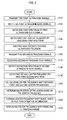
- FIG- 2 illustrates a flowchart showing a process of detecting the lesion according to one embodiment of the present invention;
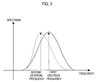
- FIG. 3 is a graph showing two center frequencies;
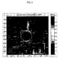
- FIG. 4 depicts an example of a center frequency shift image; and
- FIG. 5 illustrates a flowchart showing a process of detecting the lesion according to another embodiment of the present invention.
- A detailed description may be provided with reference to accompanying drawings. One of ordinary skill in the art may realize that the following description is illustrative only and is not in any way limiting. Other embodiments of the present invention may readily suggest themselves to such skilled persons having the benefit of this disclosure.
- Hereinafter, embodiments of the present invention will be described with reference to FIGS. 1 and 5. The following embodiments describe detecting a lesion based on first receive signals and second receive signals- The first receive signals are obtained with ultrasound echo signals from the lesion, which has not undergone a high intensity focused ultrasound (HIFU). Further, the second receive signals are obtained with ultrasound echo signals from the lesion, which underwent the HIFU.
- FIG. 1 illustrates an ultrasound diagnostic system according to one embodiment of the present invention- As shown in FIG. 1, an ultrasound
diagnostic system 100 may include anHIFU probe 110, anHIFU unit 120, animaging probe 130, abeamformer 140, asignal processing unit 150, animage processor 160 and adisplay unit 170. Further, the ultrasounddiagnostic system 100 may include a container (not shown in FIG. 1) for containing a medium. The container may be a water tank, a water bag and the like. The container is disposed between theHIFU probe 110 and a body (i.e., skin) when the HIFU is injected into a body. - The HIFU
probe 110 may inject the HIFU on alesion 210 in abody 200. The HIFUprobe 110 may include a number of elements. The HIFUunit 120 may provide theHIFU probe 110 with a high frequency power for generating the HIFU and control theHIFU probe 110 to inject the HIFU toward thelesion 210. As such; theHIFU unit 120 may include a power supply, a controller and a driver (not shown in FIG 1). The power supply provides the high frequency power to theHIFU probe 110. The controller generates driving signals, and the driver drives theHIFU probe 110 according to the control signals outputted from the controller to focus the HIFU onto thelesion 210. - The
imaging probe 130 may transmit ultrasound signals to thelesion 210 in thebody 200 along transmit scanlines and receive ultrasound echo signals from thelesion 210. Theimaging probe 130 may further output receive signals obtained from the ultrasound echo signals for forming an ultrasound image showing thelesion 210. Theimaging probe 130 may include a number of clements arranged in a form of 1-dimensional or a 2-dimensional array. Theimaging probe 130 may transmit ultrasound signals to a target object, namely, thelesion 210 in thebody 200. Theimaging probe 130 may receive ultrasound echo signals reflected from thelesion 210 and convert the ultrasound echo signals into the first and second receive signals. - The
beamformer 140 may provide appropriate delays to the ultrasound signals for transmission such that the ultrasound signals outputted from theimaging probe 130 are focused on a focal point Further, thebeamformer 140 focuses the receive signals by considering the arrival time of the echo signals at each element in theimaging probe 130. - According to an embodiment of the present invention, the
signal processing unit 150 may detect the center frequencies of two receive signals outputted from theimaging probe 130 and calculate the center frequency shift between the two receive signals. Thesignal processing unit 150 may include aspectrum analyzing unit 151, a centerfrequency detecting unit 152 and a center frequencyshift calculating unit 153. Thespectrum analyzing unit 151 may analyze a first spectrum and a second spectrum to produce spectrum analysis results. The first spectrum and the second spectrum are obtained from the first and the second receive signals. The centerfrequency detecting unit 152 may detect the first and second center frequencies from the analysis results, respectively. The center frequencyshift calculating unit 153 may calculate the difference between the first and second center frequencies. In other words, the center frequencyshift calculating unit 153 may calculate the shift of the first center frequency of the first receive signals due to the HIFU. The center frequency difference, namely, the center frequency shift, is a pixel value of each pixel for forming a center frequency shift image. - According to another embodiment of the present invention, the
signal processing unit 150 may also determine a position of the lesion in consideration of the center frequency shift. In such a case, thesignal processing unit 150 may further include aposition determining unit 154. Theposition determining unit 154 may determine a position of the lesion based on the center frequency shift. Specifically, theposition determining unit 154 may search a region in which pixels having pixel values within a predetermined range are adjacent to one another based on the fact that the center frequency shift is significant at the boundary of the lesion. The boundary of the region may be adopted to determine the position of the lesion boundary. - The
image processor 160 may form at least one ultrasound image showing the lesion based on the receive signals and a center frequency shift image based on the center frequency shift. Also, theimage processor 160 may form an overlap image of the ultrasound image and the center frequency shift image. Thus, theimage processor 160 may remove the background of the center frequency shift image to form a transparent center frequency shift image, which shows only the boundary of the lesion, to be overlapped with the ultrasound image. Specifically, in order to form the transparent center frequency shift image, theimage processor 160 may set the pixel values of all the pixels outside the region to zero in the center frequency shift image. According to another embodiment, theimage processor 160 may express the background of the center frequency shift image with transparency in pseudo color map so as to leave only the boundary of the lesion. - The
display unit 170 may display at least one of the ultrasound image, the center frequency shift image and the overlap image. For example, by dividing a display area of thedisplay unit 170 into a plurality of sub-areas, the ultrasound image, the center frequency shift image and the overlap image may be displayed in each respective sub-areas. - Hereinafter, a method of detecting the lesion according to one embodiment of the present invention will be described with reference to FIGS. 1 to 4.
- Referring now to FIGS. 1 and 2, the
imaging probe 130 may transmit first ultrasound signals to a lesion in a body (step S110) and receive first ultrasound echo signals (step S120). Thespectrum analyzing unit 151 may analyze the first spectrum of the first ultrasound echo signals to produce a first spectrum analysis result (step S130). Further, the centerfrequency detecting unit 152 may detect the first center frequency from the first spectrum based on the first spectrum analysis result (step S140). - The HIFU probe may inject the HIFU onto the lesion (step S150). Also, the
imaging probe 130 may transmit second ultrasound signals to the lesion, which underwent the HIFU (step S160), and receive second ultrasound echo signals (step S170). Thespectrum analyzing unit 151 may analyze a second spectrum of the second ultrasound echo signals to produce a second spectrum analysis result (step S180). The centerfrequency detecting unit 152 may detect a second center frequency from the second spectrum based on the second spectrum analysis result (step S190). - The center frequency
shift calculating unit 153 may calculate a center frequency shift, that is, a difference between the first and second center frequencies as shown in FIG. 3 (step S200). Theposition determining unit 154 may determine the position of the lesion (i.e.., boundary of the lesion) based on the center frequency shift calculated by the center frequency detecting unit 152 (step S210). The center frequency shift is a pixel value of each pixel for forming a center frequency shift image. After calculating the center frequency shift, the position determining unit 514 may search a region including pixels of which pixel values are within a predetermined range and adjacent to one another. In such a case, the position determining unit may determine the position of the lesion in consideration of a boundary of the region. - The
image processor 160 may form the center frequency shift image based on the center frequency shift (step S220). Thedisplay unit 170 may display the center frequency shift image formed in the image processor 160 (step S220). In this embodiment, thesteps step 150. - FIG. 4 depicts a center frequency shift image expressed by pixels having pixel values denoted with the central frequency shift between the first and second center frequencies. Fig. 4 shows the result based on the first and second ultrasound echo signals received at a temperature of 40°C and 70°C, respectively. In FIG. 4, the degree of the central frequency shift is denoted with a pseudo color map. In FIG. 4, a dotted circle denotes the boundary of rhe lesion. The dotted circle can be expressed with the determined position of the lesion boundary.
- Hereinafter, a method of detecting the lesion according to another embodiment of the present invention will be described with reference to FIGS. 1 and 5.
- Referring now to FIGS. 1 and 5, the HIFU probe may inject the HIFU on a
lesion 210 in a body 200 (step S510). The image probe may transmit ultrasound signals to the lesion when the HIFU is injected onto the lesion 210 (step S520) and receive former and latter ultrasound echo signals from the lesion. Theimage probe 130 may convert the former and latter ultrasound echo signals into former and latter receive signals (step S530). The signal processor may detect the center frequencies of the former and latter receive signals (step S540) and calculate the center frequency shift between the former and latter receive signals (step S550). The center frequency shift is a pixel value of each pixel for forming a center frequency shift image. After calculating the center frequency shift, thesignal processor 150 may search a region including pixels of which pixel values are within a predetermined range and adjacent to one another. Also, thesignal processor 150 may determine a position of the lesion based on the center frequency shift (step S560). In case that the signal processor searches the region, the position of the lesion may be determined in consideration of a boundary of the region. Theimage processor 160 may form the center frequency shift image based on the center frequency shift (step S570), while the display unit may display the center frequency shift image (step S580). - By using the embodiments, thermal diffusion due to injection of the HIFU can be detected.
- In the above-described embodiment, the lesion is detected based on the difference of the center frequencies of the first and second ultrasound echo signals, which are obtained before and after the lesion undergoes the HIFU. However, in another embodiment, the lesion may be detected based on the ultrasound echo signals, which are successively obtained when the HIFU is injected onto the lesion, until the lesion is removed. In this embodiment, the center frequencies of former ultrasound receive signals and latter ultrasound receive signals are compared in order to obtain the center frequency shift.
- As described above, in accordance with the present invention, the image showing the thermal diffusion due to the temperature difference generated by applying the high intensity focused ultrasound can be provided in real time to the user. Thus, the user can remove the lesion accurately while observing the thermal diffusion in real time during treatment.
- An embodiment may be achieved in whole or in parts by an ultrasound diagnostic system, which includes: a high intensity frequency ultrasound (HIFU) probe for injecting the HIFU on a lesion in a body; an imaging probe for transmitting ultrasound signals to the lesion, receiving ultrasound echo signals from the lesion, and outputting receive signals obtained from the ultrasound echo signals; a signal processing unit for detecting center frequencies of two receive signals outputted from the imaging probe and calculating center frequency shift between the two receive signals; an image processor for forming at least one ultrasound image showing the lesion based on the receive signals and a center frequency shift image based on center frequency shift; and a display unit for displaying the ultrasound image and the center frequency shift image.
- Another embodiment may be achieved in whole or in parts by an ultrasound diagnostic system, which includes: a high intensity frequency ultrasound (HIFU) probe for injecting the HIFU on a lesion in a body; an imaging probe for transmitting ultrasound signals to the lesion, receiving ultrasound echo signals from the lesion, and outputting receive signals obtained from the ultrasound echo signals; a signal processing unit for detecting center frequencies of two receive signals outputted from the imaging probe, calculating center frequency shift between the two receive signals and determining a position of the lesion in consideration of the center frequency shift; an image processor for forming at least one ultrasound image showing the lesion based on the receive signals and a center frequency shift image based on center frequency shift; and a display unit for displaying the ultrasound image and the center frequency shift image.
- An embodiment may be achieved in whole or in parts by a method of detecting a lesion in a body, which includes: transmitting ultrasound signals to a lesion in a body; receiving first ultrasound echo signals from the lesion; injecting high intensity frequency ultrasound (HIFU) on the lesion; transmitting ultrasound signals to a lesion in a body; receiving second ultrasound echo signals from the lesion; obtaining first receive signals from the first ultrasound echo signals and second receive signals from the second ultrasound echo signals; detecting center frequencies of the first and second receive signals; calculating center frequency shift between the first and second receive signals, wherein the center frequency shift is a pixel value of each pixel for forming a center frequency shift image; determining a position of the lesion in consideration of the center frequency shift; forming the center frequency shift image based on the center frequency shift; and displaying the center frequency shift image.
- Another embodiment may be achieved in whole or in parts by a method of detecting a lesion in a body, which includes injecting a high intensity frequency ultrasound (HIFU) on a lesion in a body; transmitting ultrasound signals to the lesion when the HIFU is injected on the lesion; obtaining former and latter receive signals with ultrasound echo signals from the lesion, successively, when the HIFU is injected on the lesion; detecting center frequencies of the former and latter receive signals; calculating center frequency shift between the former and latter receive signals, wherein the center frequency shift is a pixel value of each pixel for forming a center frequency shift image; determining a position of the lesion in consideration of the center frequency shift; forming the center frequency shift image based on the center frequency shift; and displaying the center frequency shift image.
- Any reference in this specification to "one embodiment," "an embodiment," "example embodiment," etc., means that a particular feature, structure or characteristic described in connection with the embodiment is included in at least one embodiment of the invention. The appearances of such phrases in various places in the specification are not necessarily all referring to the same embodiment. Further, when a particular feature, structure or characteristic is described in connection with any embodiment, it is submitted that it is within the purview of one skilled in the art to effect such feature, structure or characteristic in connection with other ones of the embodiments.
- Although embodiments have been described with reference to a number of illustrative embodiments thereof, it should be understood that numerous other modifications and embodiments can be devised by those skilled in the art that will fall within the spirit and scope of the principles of this disclosure. More particularly, various variations and modifications are possible in the component parts and/or arrangements of the subject combination arrangement within the scope of the disclosure, the drawings and the appended claims. In addition to variations and modifications in the component parts and/or arrangements, alternative uses will also be apparent to those skilled in the art
Claims (19)
- An ultrasound diagnostic system, comprising:a high intensity frequency ultrasound (HIFU) probe for injecting the HIFU on a lesion in a body;an imaging probe for transmitting ultrasound signals to the lesion and receiving ultrasound echo signals from the lesion, the imaging probe further being configured to output receive signals obtained from the ultrasound echo signals;a signal processing unit for detecting center frequencies of two receive signals outputted from the imaging probe and calculating center frequency shift between the two receive signals;an image processor fot forming at least one ultrasound image showing the lesion based on the receive signals and a center frequency shift image based on center frequency shift; anda display unit for displaying the ultrasound image and the center frequency shift image.
- The ultrasound diagnostic system of Claim 1, wherein the two receive signals include:first receive signals obtained by the ultrasound echo signals from the lesion having not undergone the HIFU; andsecond receive signals obtained by the ultrasound echo signal from the lesion having undergone the HIFU.
- The ultrasound diagnostic system of Claim 1, wherein the two receive signals include:former receive signals and latter receive signals successively obtained when the HIFU is injected to the lesion until the lesion is removed.
- The ultrasound diagnostic system of Claim 1, wherein the signal processing unit includes:a spectrum analyzing unit for analyzing spectra of the two receive signals to produce spectrum analysis results;a center frequency detecting unit for detecting center frequencies of the two receive signals, respectively, based on the spectrum analysis results; anda center frequency shift calculating unit for calculating the center frequency shift between the two receive signals.
- The ultrasound diagnostic system of Claim 1, wherein the image processor forms an overlap image of the ultrasound image and the center frequency shift image, and wherein the display unit displays the overlap image.
- The ultrasound diagnostic system of Claim 5, wherein the image processor sets the pixel values of pixels outside a region corresponding to the lesion to zero in the center frequency shift image and forms a transparent center frequency shift image to be overlapped with the ultrasound image.
- The ultrasound diagnostic system of Claim 4, further comprising a container for containing a medium, wherein the contained medium is disposed between the HIFU probe and the body.
- An ultrasound diagnostic system, comprising:a high intensity frequency ultrasound (HIFU) probe for injecting the HIFU on a lesion in a body;an imaging probe for transmitting ultrasound signals to the lesion and receiving ultrasound echo signals from the lesion, the imaging probe further being configured to output receive signals obtained from the ultrasound echo signals;a signal processing unit for detecting center frequencies of two receive signals outputted from the imaging probe and calculating center frequency shift between the two receive signals, the signal processing unit further being configured to determine a position of the lesion in consideration of the center frequency shift;an image processor for forming at least one ultrasound image showing the lesion based on the receive signals and a center frequency shift image based on center frequency shift; anda display unit for displaying the ultrasound image and the center frequency shift image.
- The ultrasound diagnostic system of Claim 8, wherein the signal processing unit includes:a spectrum analyzing unit for analyzing spectra of the two receive signals to produce spectrum analysis results;a center frequency detecting unit for detecting center frequencies of the two receive signals, respectively, based on the spectrum analysis results;a center frequency shift calculating unit for calculating the center frequency shift between the two receive signals; anda position determining unit for determining the position of the lesion based on the center frequency shift
- The ultrasound diagnostic system of Claim 9, wherein the center frequency shift is a pixel value of each pixel for forming the center frequency shift image, and wherein the position determining unit searches a region including pixels adjacent to one another, and wherein the pixel values of the pixels in the region are within a predetermined range.
- The ultrasound diagnostic system of Claim 9, wherein the two receive signals include:first receive signals obtained by the ultrasound echo signals from the lesion having not undergone the HIFU; andsecond receive signals obtained by the ultrasound echo signal from the lesion having undergone the HIFU.
- The ultrasound diagnostic system of Claim 9, wherein the two receive signals include:former receive signals and latter receive signals successively obtained when the HIFU is injected to the lesion until the lesion is removed.
- The ultrasound diagnostic system of Claim 9, wherein the image processor forms an overlap image of the ultrasound image and the center frequency shift image, and wherein the display unit displays the overlap image.
- The ultrasound diagnostic system of Claim 10, wherein the image processor sets the pixel values of pixels outside the region to zero in the center frequency shift image and forms a transparent center frequency shift image to be overlapped with the ultrasound image,
- The ultrasound diagnostic system of Claim 9, further comprising a container for containing a medium, wherein the contained medium is disposed between the HIFU probe and the body.
- A method of detecting a lesion in a body, comprising:transmitting ultrasound signals to a lesion in a bodyreceiving first ultrasound echo signals from the lesion;injecting high intensity frequency ultrasound (HIFU) on the lesion;transmitting ultrasound signals to a lesion in a body;receiving second ultrasound echo signals from the lesion;obtaining first receive signals from the first ultrasound echo signals and second receive signals from the second ultrasound echo signals;detecting center frequencies of the first and second receive signals;calculating center frequency shift between the first and second receive signals, wherein the center frequency shift is a pixel value of each pixel for forming a center frequency shift image;determining a position of the lesion in consideration of the center frequency shift;forming the center frequency shift image based on the center frequency shift; anddisplaying the center frequency shift image.
- The method of Claim 16, wherein the first receive signal obtained by the ultrasound echo signals from the lesion having not undergone the HIFU, and wherein the second receive signals obtained by the ultrasound echo signal from the lesion having undergone the HIFU.
- A method of detecting a lesion in a body, comprising:injecting a high intensity frequency ultrasound (HIFU) on a lesion in a body;transmitting ultrasound signals to the lesion when the HIFU is injected on the lesion;obtaining former and latter receive signals with ultrasound echo signals from the lesion, successively, when the HIFU is injected on the lesion;detecting center frequencies of the former and latter receive signals;calculating center frequency shift between the former and latter receive signals, wherein the center frequency shift is a pixel value of each pixel for forming a center frequency shift image;determining a position of the lesion in consideration of the center frequency shift;forming the center frequency shift image based on the center frequency shift; anddisplaying the center frequency shift image.
- The method of Claim 18, further comprising:searching a region including pixels adjacent to one another, wherein the pixel values of the pixels in the region are within a predetermined range, and wherein the position of the lesion is determined in consideration of a boundary of the region.
Applications Claiming Priority (1)
| Application Number | Priority Date | Filing Date | Title |
|---|---|---|---|
| KR1020050131293A KR100932472B1 (en) | 2005-12-28 | 2005-12-28 | Ultrasound Diagnostic System for Detecting Lesions |
Publications (3)
| Publication Number | Publication Date |
|---|---|
| EP1803403A2 true EP1803403A2 (en) | 2007-07-04 |
| EP1803403A3 EP1803403A3 (en) | 2010-12-29 |
| EP1803403B1 EP1803403B1 (en) | 2012-07-11 |
Family
ID=37885819
Family Applications (1)
| Application Number | Title | Priority Date | Filing Date |
|---|---|---|---|
| EP06026933A Active EP1803403B1 (en) | 2005-12-28 | 2006-12-27 | Ultrasound diagnostic system of detecting a lesion |
Country Status (4)
| Country | Link |
|---|---|
| US (1) | US20070167774A1 (en) |
| EP (1) | EP1803403B1 (en) |
| JP (1) | JP2007181698A (en) |
| KR (1) | KR100932472B1 (en) |
Families Citing this family (26)
| Publication number | Priority date | Publication date | Assignee | Title |
|---|---|---|---|---|
| US8012093B2 (en) * | 2005-07-27 | 2011-09-06 | Medison Co., Ltd. | Ultra sound system for forming strain images with instantaneous frequency |
| KR100969547B1 (en) * | 2008-07-15 | 2010-07-12 | 주식회사 메디슨 | Ultrasound system provides surgical procedure information |
| US20100286518A1 (en) * | 2009-05-11 | 2010-11-11 | General Electric Company | Ultrasound system and method to deliver therapy based on user defined treatment spaces |
| US20100286520A1 (en) * | 2009-05-11 | 2010-11-11 | General Electric Company | Ultrasound system and method to determine mechanical properties of a target region |
| US20100286519A1 (en) * | 2009-05-11 | 2010-11-11 | General Electric Company | Ultrasound system and method to automatically identify and treat adipose tissue |
| EP2439505A1 (en) * | 2010-10-04 | 2012-04-11 | Koninklijke Philips Electronics N.V. | Radiation force balance calibrator |
| KR101317359B1 (en) * | 2011-09-29 | 2013-10-11 | 서강대학교산학협력단 | Ultrasound imaging system of generating a HIFU focus image and method of generating it |
| KR101334375B1 (en) * | 2012-07-31 | 2013-11-29 | 서강대학교산학협력단 | Method and apparatus of cancelling residual hifu interference |
| KR101312307B1 (en) * | 2011-10-13 | 2013-09-27 | 서강대학교산학협력단 | ultrasound signal processing Method for removing HIFU signal, Apparatus thereof |
| CN103974665B (en) * | 2011-10-13 | 2016-04-06 | 西江大学校产学协力团 | HIFU interfering signal removing method and device |
| KR101580254B1 (en) * | 2012-03-14 | 2015-12-24 | 삼성전자 주식회사 | Apparatus and method for diagnosis of medical image in a frequency domain |
| KR101474309B1 (en) * | 2013-03-21 | 2014-12-18 | 가톨릭관동대학교산학협력단 | Fixing apparatus for ultrasonic probe |
| KR101627319B1 (en) * | 2014-03-14 | 2016-06-03 | 알피니언메디칼시스템 주식회사 | medical image processor and method thereof for medical diagnosis |
| EP3585267B1 (en) * | 2016-07-17 | 2025-09-10 | Nina Medical Ltd. | Doppler guided ultrasound therapy |
| JP7094843B2 (en) * | 2018-09-14 | 2022-07-04 | オリンパス株式会社 | Ultrasound observing device, how to operate the ultrasonic observing device, computer-readable recording medium and ultrasonic diagnostic system |
| KR102490019B1 (en) * | 2019-12-13 | 2023-01-18 | 한국과학기술원 | Method and apparatus for quantitative imaging using ultrasound data |
| US12144685B2 (en) | 2019-12-13 | 2024-11-19 | Korea Advanced Institute Of Science And Technology | Method and apparatus for quantitative ultrasound imaging using single-ultrasound probe |
| US12315641B2 (en) | 2019-12-13 | 2025-05-27 | Korea Advanced Institute Of Science And Technology | Method and apparatus for quantitative imaging using ultrasound data |
| KR102380167B1 (en) * | 2019-12-13 | 2022-03-29 | 한국과학기술원 | Method and apparatus for quantitative ultrasound imaging using single-ultrasound probe |
| EP4516237A3 (en) | 2020-05-19 | 2025-04-16 | Coravie Medical, Inc. | Injectable hemodynamic monitoring systems |
| KR102525286B1 (en) * | 2020-11-19 | 2023-04-25 | (주)메사메디칼 | Probe head with non-contact infrared temperature measuring device, high intensity focused ultrasonic device including the head, and automatic ultrasonic output control method using the device |
| KR102655333B1 (en) * | 2021-01-25 | 2024-04-05 | 한국과학기술원 | Method and apparatus for multi-variable quantitative imaging using ultrasound data |
| KR102787516B1 (en) * | 2021-07-14 | 2025-04-01 | 한국과학기술원 | Method and apparatus for extracting quantitative information in medical ultrasound |
| KR102750288B1 (en) * | 2021-07-14 | 2025-01-07 | 한국과학기술원 | Method and apparatus for quantitative imaging in medical ultrasound |
| WO2023287083A1 (en) * | 2021-07-14 | 2023-01-19 | 한국과학기술원 | Method and device for quantitative imaging in medical ultrasound |
| WO2023287084A1 (en) | 2021-07-14 | 2023-01-19 | 한국과학기술원 | Method and device for extracting medical ultrasonic quantitative information |
Family Cites Families (19)
| Publication number | Priority date | Publication date | Assignee | Title |
|---|---|---|---|---|
| FR2664819B1 (en) * | 1990-07-23 | 1994-04-29 | Edap Int | ULTRA-FAST EXTRACORPOREAL ULTRASONIC HYPERTHERMAL APPARATUS. |
| US4574635A (en) * | 1984-11-02 | 1986-03-11 | North American Philips Corporation | Monitoring of frequency shift of ultrasound pulses in tissue |
| JPH0871069A (en) * | 1994-09-02 | 1996-03-19 | Toshiba Corp | Ultrasonic therapy equipment |
| FR2778573B1 (en) * | 1998-05-13 | 2000-09-22 | Technomed Medical Systems | FREQUENCY ADJUSTMENT IN A HIGH INTENSITY FOCUSED ULTRASOUND TREATMENT APPARATUS |
| US7520856B2 (en) * | 1999-09-17 | 2009-04-21 | University Of Washington | Image guided high intensity focused ultrasound device for therapy in obstetrics and gynecology |
| US7166075B2 (en) * | 2002-03-08 | 2007-01-23 | Wisconsin Alumni Research Foundation | Elastographic imaging of in vivo soft tissue |
| KR100459616B1 (en) | 2002-04-17 | 2004-12-04 | 주식회사 메디슨 | Ultrasonic diagnostic apparatus and method for measuring human tissue velocities using doppler effect |
| US6716168B2 (en) * | 2002-04-30 | 2004-04-06 | Siemens Medical Solutions Usa, Inc. | Ultrasound drug delivery enhancement and imaging systems and methods |
| JP4067914B2 (en) | 2002-08-21 | 2008-03-26 | アロカ株式会社 | Ultrasonic diagnostic equipment |
| JP4342167B2 (en) | 2002-11-12 | 2009-10-14 | 株式会社東芝 | Ultrasonic irradiation device |
| WO2004075987A1 (en) * | 2003-02-28 | 2004-09-10 | Koninklijke Philips Electronics, N.V. | Motion-tracking improvements for hifu ultrasound therapy |
| JP2005000530A (en) * | 2003-06-13 | 2005-01-06 | Toshiba Corp | Ultrasonic irradiation apparatus and ultrasonic irradiation method |
| JP2005058533A (en) | 2003-08-14 | 2005-03-10 | Matsushita Electric Ind Co Ltd | Ultrasonic diagnostic equipment |
| JP4657106B2 (en) * | 2003-11-21 | 2011-03-23 | 株式会社日立メディコ | Ultrasonic diagnostic equipment |
| JP4583068B2 (en) * | 2004-05-11 | 2010-11-17 | 株式会社東芝 | Ultrasonic diagnostic equipment |
| CN100401975C (en) * | 2004-06-04 | 2008-07-16 | 北京源德生物医学工程有限公司 | Supersonic inverting method for measuring temperature of human or animal body |
| US8211019B2 (en) * | 2005-01-21 | 2012-07-03 | Chikayoshi Sumi | Clinical apparatuses |
| CN1814323B (en) * | 2005-01-31 | 2010-05-12 | 重庆海扶(Hifu)技术有限公司 | A Focused Ultrasonic Therapy System |
| US7405510B2 (en) * | 2005-07-20 | 2008-07-29 | Ust, Inc. | Thermally enhanced piezoelectric element |
-
2005
- 2005-12-28 KR KR1020050131293A patent/KR100932472B1/en not_active Expired - Lifetime
-
2006
- 2006-12-27 EP EP06026933A patent/EP1803403B1/en active Active
- 2006-12-28 US US11/617,245 patent/US20070167774A1/en not_active Abandoned
- 2006-12-28 JP JP2006356010A patent/JP2007181698A/en active Pending
Non-Patent Citations (1)
| Title |
|---|
| None |
Also Published As
| Publication number | Publication date |
|---|---|
| EP1803403B1 (en) | 2012-07-11 |
| JP2007181698A (en) | 2007-07-19 |
| US20070167774A1 (en) | 2007-07-19 |
| KR100932472B1 (en) | 2009-12-18 |
| KR20070069322A (en) | 2007-07-03 |
| EP1803403A3 (en) | 2010-12-29 |
Similar Documents
| Publication | Publication Date | Title |
|---|---|---|
| EP1803403B1 (en) | Ultrasound diagnostic system of detecting a lesion | |
| US8998812B2 (en) | Ultrasound method and probe for electromagnetic noise cancellation | |
| US8784317B2 (en) | Signal processing apparatus, ultrasonic apparatus, control method for signal processing apparatus, and control method for ultrasonic apparatus | |
| Jensen | Medical ultrasound imaging | |
| Vignon et al. | Capon beamforming in medical ultrasound imaging with focused beams | |
| CN103347450B (en) | Ultrasonic diagnostic apparatus and method | |
| CN102481142B (en) | Method and apparatus for ultrasonic detection and imaging of hemodynamic information, particularly venous blood flow information | |
| CN114364325B (en) | Ultrasonic diagnostic apparatus and control method for ultrasonic diagnostic apparatus | |
| CN107708575A (en) | Method, system and computer program product for single track location shear wave elastography | |
| US11337673B2 (en) | Using reflected shear waves for monitoring lesion growth in thermal ablations | |
| EP2578162A1 (en) | Ultrasound diagnosis device | |
| US9448100B2 (en) | Signal processing apparatus | |
| CN107205720A (en) | Ultrasonic adaptive beam forming method and application thereof to transcranial imaging | |
| CN111093512A (en) | Ultrasound imaging method and ultrasound imaging apparatus | |
| US20250199146A1 (en) | Apparatus, system and method to compound signals of respective received ultrasonic frequencies to generate an output ultrasonic image | |
| CN116419717A (en) | Method and system for ultrasonic characterization of media | |
| JP2004528921A (en) | Coherent reflector detection in noisy ultrasound data | |
| JP2011110102A (en) | Ultrasonic diagnostic apparatus | |
| JP4909132B2 (en) | Optical tomography equipment | |
| JP7470167B2 (en) | Method and system for determining physical properties of a medium - Patents.com | |
| EP3639750A1 (en) | Systems and methods for tracking a tool in an ultrasound image | |
| Martin | Basic equipment, components and image production | |
| Adachi et al. | Improvement of spatial resolution for third harmonic detection using a separately arranged transmitting/receiving ultrasonic transducer | |
| HK40063959B (en) | Method and system for ultrasonic characterisation of a medium | |
| Fairhead | Sounds far-fetched? The technical basis of B-mode ultrasound |
Legal Events
| Date | Code | Title | Description |
|---|---|---|---|
| PUAI | Public reference made under article 153(3) epc to a published international application that has entered the european phase |
Free format text: ORIGINAL CODE: 0009012 |
|
| AK | Designated contracting states |
Kind code of ref document: A2 Designated state(s): AT BE BG CH CY CZ DE DK EE ES FI FR GB GR HU IE IS IT LI LT LU LV MC NL PL PT RO SE SI SK TR |
|
| AX | Request for extension of the european patent |
Extension state: AL BA HR MK YU |
|
| PUAL | Search report despatched |
Free format text: ORIGINAL CODE: 0009013 |
|
| AK | Designated contracting states |
Kind code of ref document: A3 Designated state(s): AT BE BG CH CY CZ DE DK EE ES FI FR GB GR HU IE IS IT LI LT LU LV MC NL PL PT RO SE SI SK TR |
|
| AX | Request for extension of the european patent |
Extension state: AL BA HR MK RS |
|
| RIC1 | Information provided on ipc code assigned before grant |
Ipc: A61N 7/02 20060101ALN20101123BHEP Ipc: A61B 8/08 20060101AFI20101123BHEP |
|
| 17P | Request for examination filed |
Effective date: 20110622 |
|
| 17Q | First examination report despatched |
Effective date: 20110729 |
|
| AKX | Designation fees paid |
Designated state(s): AT BE BG CH CY CZ DE DK EE ES FI FR GB GR HU IE IS IT LI LT LU LV MC NL PL PT RO SE SI SK TR |
|
| REG | Reference to a national code |
Ref country code: DE Ref legal event code: R079 Ref document number: 602006030635 Country of ref document: DE Free format text: PREVIOUS MAIN CLASS: A61B0008000000 Ipc: A61B0008080000 |
|
| GRAP | Despatch of communication of intention to grant a patent |
Free format text: ORIGINAL CODE: EPIDOSNIGR1 |
|
| RIC1 | Information provided on ipc code assigned before grant |
Ipc: A61N 7/02 20060101ALN20111116BHEP Ipc: A61B 8/08 20060101AFI20111116BHEP |
|
| RTI1 | Title (correction) |
Free format text: ULTRASOUND DIAGNOSTIC SYSTEM OF DETECTING A LESION |
|
| GRAS | Grant fee paid |
Free format text: ORIGINAL CODE: EPIDOSNIGR3 |
|
| GRAA | (expected) grant |
Free format text: ORIGINAL CODE: 0009210 |
|
| AK | Designated contracting states |
Kind code of ref document: B1 Designated state(s): AT BE BG CH CY CZ DE DK EE ES FI FR GB GR HU IE IS IT LI LT LU LV MC NL PL PT RO SE SI SK TR |
|
| RAP1 | Party data changed (applicant data changed or rights of an application transferred) |
Owner name: SAMSUNG MEDISON CO., LTD. |
|
| REG | Reference to a national code |
Ref country code: GB Ref legal event code: FG4D |
|
| REG | Reference to a national code |
Ref country code: CH Ref legal event code: EP |
|
| REG | Reference to a national code |
Ref country code: AT Ref legal event code: REF Ref document number: 565651 Country of ref document: AT Kind code of ref document: T Effective date: 20120715 |
|
| REG | Reference to a national code |
Ref country code: IE Ref legal event code: FG4D |
|
| REG | Reference to a national code |
Ref country code: DE Ref legal event code: R096 Ref document number: 602006030635 Country of ref document: DE Effective date: 20120906 |
|
| REG | Reference to a national code |
Ref country code: NL Ref legal event code: T3 |
|
| REG | Reference to a national code |
Ref country code: AT Ref legal event code: MK05 Ref document number: 565651 Country of ref document: AT Kind code of ref document: T Effective date: 20120711 |
|
| REG | Reference to a national code |
Ref country code: LT Ref legal event code: MG4D Effective date: 20120711 |
|
| PG25 | Lapsed in a contracting state [announced via postgrant information from national office to epo] |
Ref country code: CY Free format text: LAPSE BECAUSE OF FAILURE TO SUBMIT A TRANSLATION OF THE DESCRIPTION OR TO PAY THE FEE WITHIN THE PRESCRIBED TIME-LIMIT Effective date: 20120711 Ref country code: IS Free format text: LAPSE BECAUSE OF FAILURE TO SUBMIT A TRANSLATION OF THE DESCRIPTION OR TO PAY THE FEE WITHIN THE PRESCRIBED TIME-LIMIT Effective date: 20121111 Ref country code: AT Free format text: LAPSE BECAUSE OF FAILURE TO SUBMIT A TRANSLATION OF THE DESCRIPTION OR TO PAY THE FEE WITHIN THE PRESCRIBED TIME-LIMIT Effective date: 20120711 Ref country code: FI Free format text: LAPSE BECAUSE OF FAILURE TO SUBMIT A TRANSLATION OF THE DESCRIPTION OR TO PAY THE FEE WITHIN THE PRESCRIBED TIME-LIMIT Effective date: 20120711 Ref country code: LT Free format text: LAPSE BECAUSE OF FAILURE TO SUBMIT A TRANSLATION OF THE DESCRIPTION OR TO PAY THE FEE WITHIN THE PRESCRIBED TIME-LIMIT Effective date: 20120711 Ref country code: BE Free format text: LAPSE BECAUSE OF FAILURE TO SUBMIT A TRANSLATION OF THE DESCRIPTION OR TO PAY THE FEE WITHIN THE PRESCRIBED TIME-LIMIT Effective date: 20120711 |
|
| PG25 | Lapsed in a contracting state [announced via postgrant information from national office to epo] |
Ref country code: LV Free format text: LAPSE BECAUSE OF FAILURE TO SUBMIT A TRANSLATION OF THE DESCRIPTION OR TO PAY THE FEE WITHIN THE PRESCRIBED TIME-LIMIT Effective date: 20120711 Ref country code: SI Free format text: LAPSE BECAUSE OF FAILURE TO SUBMIT A TRANSLATION OF THE DESCRIPTION OR TO PAY THE FEE WITHIN THE PRESCRIBED TIME-LIMIT Effective date: 20120711 Ref country code: PT Free format text: LAPSE BECAUSE OF FAILURE TO SUBMIT A TRANSLATION OF THE DESCRIPTION OR TO PAY THE FEE WITHIN THE PRESCRIBED TIME-LIMIT Effective date: 20121112 Ref country code: PL Free format text: LAPSE BECAUSE OF FAILURE TO SUBMIT A TRANSLATION OF THE DESCRIPTION OR TO PAY THE FEE WITHIN THE PRESCRIBED TIME-LIMIT Effective date: 20120711 Ref country code: SE Free format text: LAPSE BECAUSE OF FAILURE TO SUBMIT A TRANSLATION OF THE DESCRIPTION OR TO PAY THE FEE WITHIN THE PRESCRIBED TIME-LIMIT Effective date: 20120711 Ref country code: GR Free format text: LAPSE BECAUSE OF FAILURE TO SUBMIT A TRANSLATION OF THE DESCRIPTION OR TO PAY THE FEE WITHIN THE PRESCRIBED TIME-LIMIT Effective date: 20121012 |
|
| PG25 | Lapsed in a contracting state [announced via postgrant information from national office to epo] |
Ref country code: EE Free format text: LAPSE BECAUSE OF FAILURE TO SUBMIT A TRANSLATION OF THE DESCRIPTION OR TO PAY THE FEE WITHIN THE PRESCRIBED TIME-LIMIT Effective date: 20120711 Ref country code: ES Free format text: LAPSE BECAUSE OF FAILURE TO SUBMIT A TRANSLATION OF THE DESCRIPTION OR TO PAY THE FEE WITHIN THE PRESCRIBED TIME-LIMIT Effective date: 20121022 Ref country code: CZ Free format text: LAPSE BECAUSE OF FAILURE TO SUBMIT A TRANSLATION OF THE DESCRIPTION OR TO PAY THE FEE WITHIN THE PRESCRIBED TIME-LIMIT Effective date: 20120711 Ref country code: RO Free format text: LAPSE BECAUSE OF FAILURE TO SUBMIT A TRANSLATION OF THE DESCRIPTION OR TO PAY THE FEE WITHIN THE PRESCRIBED TIME-LIMIT Effective date: 20120711 Ref country code: DK Free format text: LAPSE BECAUSE OF FAILURE TO SUBMIT A TRANSLATION OF THE DESCRIPTION OR TO PAY THE FEE WITHIN THE PRESCRIBED TIME-LIMIT Effective date: 20120711 |
|
| PLBE | No opposition filed within time limit |
Free format text: ORIGINAL CODE: 0009261 |
|
| STAA | Information on the status of an ep patent application or granted ep patent |
Free format text: STATUS: NO OPPOSITION FILED WITHIN TIME LIMIT |
|
| PG25 | Lapsed in a contracting state [announced via postgrant information from national office to epo] |
Ref country code: SK Free format text: LAPSE BECAUSE OF FAILURE TO SUBMIT A TRANSLATION OF THE DESCRIPTION OR TO PAY THE FEE WITHIN THE PRESCRIBED TIME-LIMIT Effective date: 20120711 |
|
| 26N | No opposition filed |
Effective date: 20130412 |
|
| PG25 | Lapsed in a contracting state [announced via postgrant information from national office to epo] |
Ref country code: BG Free format text: LAPSE BECAUSE OF FAILURE TO SUBMIT A TRANSLATION OF THE DESCRIPTION OR TO PAY THE FEE WITHIN THE PRESCRIBED TIME-LIMIT Effective date: 20121011 Ref country code: MC Free format text: LAPSE BECAUSE OF NON-PAYMENT OF DUE FEES Effective date: 20121231 |
|
| REG | Reference to a national code |
Ref country code: CH Ref legal event code: PL |
|
| REG | Reference to a national code |
Ref country code: DE Ref legal event code: R097 Ref document number: 602006030635 Country of ref document: DE Effective date: 20130412 |
|
| GBPC | Gb: european patent ceased through non-payment of renewal fee |
Effective date: 20121227 |
|
| REG | Reference to a national code |
Ref country code: IE Ref legal event code: MM4A |
|
| PG25 | Lapsed in a contracting state [announced via postgrant information from national office to epo] |
Ref country code: IE Free format text: LAPSE BECAUSE OF NON-PAYMENT OF DUE FEES Effective date: 20121227 Ref country code: CH Free format text: LAPSE BECAUSE OF NON-PAYMENT OF DUE FEES Effective date: 20121231 Ref country code: LI Free format text: LAPSE BECAUSE OF NON-PAYMENT OF DUE FEES Effective date: 20121231 |
|
| PG25 | Lapsed in a contracting state [announced via postgrant information from national office to epo] |
Ref country code: GB Free format text: LAPSE BECAUSE OF NON-PAYMENT OF DUE FEES Effective date: 20121227 |
|
| PG25 | Lapsed in a contracting state [announced via postgrant information from national office to epo] |
Ref country code: TR Free format text: LAPSE BECAUSE OF FAILURE TO SUBMIT A TRANSLATION OF THE DESCRIPTION OR TO PAY THE FEE WITHIN THE PRESCRIBED TIME-LIMIT Effective date: 20120711 |
|
| PG25 | Lapsed in a contracting state [announced via postgrant information from national office to epo] |
Ref country code: LU Free format text: LAPSE BECAUSE OF NON-PAYMENT OF DUE FEES Effective date: 20121227 |
|
| PG25 | Lapsed in a contracting state [announced via postgrant information from national office to epo] |
Ref country code: HU Free format text: LAPSE BECAUSE OF FAILURE TO SUBMIT A TRANSLATION OF THE DESCRIPTION OR TO PAY THE FEE WITHIN THE PRESCRIBED TIME-LIMIT Effective date: 20061227 |
|
| REG | Reference to a national code |
Ref country code: FR Ref legal event code: PLFP Year of fee payment: 10 |
|
| REG | Reference to a national code |
Ref country code: FR Ref legal event code: PLFP Year of fee payment: 11 |
|
| REG | Reference to a national code |
Ref country code: FR Ref legal event code: PLFP Year of fee payment: 12 |
|
| REG | Reference to a national code |
Ref country code: FR Ref legal event code: PLFP Year of fee payment: 13 |
|
| PGFP | Annual fee paid to national office [announced via postgrant information from national office to epo] |
Ref country code: NL Payment date: 20191106 Year of fee payment: 14 |
|
| REG | Reference to a national code |
Ref country code: NL Ref legal event code: MM Effective date: 20210101 |
|
| PG25 | Lapsed in a contracting state [announced via postgrant information from national office to epo] |
Ref country code: NL Free format text: LAPSE BECAUSE OF NON-PAYMENT OF DUE FEES Effective date: 20210101 |
|
| PGFP | Annual fee paid to national office [announced via postgrant information from national office to epo] |
Ref country code: DE Payment date: 20251105 Year of fee payment: 20 |
|
| PGFP | Annual fee paid to national office [announced via postgrant information from national office to epo] |
Ref country code: IT Payment date: 20251106 Year of fee payment: 20 |
|
| PGFP | Annual fee paid to national office [announced via postgrant information from national office to epo] |
Ref country code: FR Payment date: 20251111 Year of fee payment: 20 |